EP0860833B1 - Frame damper - Google Patents
Frame damper Download PDFInfo
- Publication number
- EP0860833B1 EP0860833B1 EP98301277A EP98301277A EP0860833B1 EP 0860833 B1 EP0860833 B1 EP 0860833B1 EP 98301277 A EP98301277 A EP 98301277A EP 98301277 A EP98301277 A EP 98301277A EP 0860833 B1 EP0860833 B1 EP 0860833B1
- Authority
- EP
- European Patent Office
- Prior art keywords
- disk
- elastic body
- frame
- damper
- body frame
- Prior art date
- Legal status (The legal status is an assumption and is not a legal conclusion. Google has not performed a legal analysis and makes no representation as to the accuracy of the status listed.)
- Expired - Lifetime
Links
Images

Classifications
-
- F—MECHANICAL ENGINEERING; LIGHTING; HEATING; WEAPONS; BLASTING
- F16—ENGINEERING ELEMENTS AND UNITS; GENERAL MEASURES FOR PRODUCING AND MAINTAINING EFFECTIVE FUNCTIONING OF MACHINES OR INSTALLATIONS; THERMAL INSULATION IN GENERAL
- F16F—SPRINGS; SHOCK-ABSORBERS; MEANS FOR DAMPING VIBRATION
- F16F15/00—Suppression of vibrations in systems; Means or arrangements for avoiding or reducing out-of-balance forces, e.g. due to motion
-
- G—PHYSICS
- G11—INFORMATION STORAGE
- G11B—INFORMATION STORAGE BASED ON RELATIVE MOVEMENT BETWEEN RECORD CARRIER AND TRANSDUCER
- G11B19/00—Driving, starting, stopping record carriers not specifically of filamentary or web form, or of supports therefor; Control thereof; Control of operating function ; Driving both disc and head
- G11B19/20—Driving; Starting; Stopping; Control thereof
- G11B19/2009—Turntables, hubs and motors for disk drives; Mounting of motors in the drive
- G11B19/2018—Incorporating means for passive damping of vibration, either in the turntable, motor or mounting
-
- F—MECHANICAL ENGINEERING; LIGHTING; HEATING; WEAPONS; BLASTING
- F16—ENGINEERING ELEMENTS AND UNITS; GENERAL MEASURES FOR PRODUCING AND MAINTAINING EFFECTIVE FUNCTIONING OF MACHINES OR INSTALLATIONS; THERMAL INSULATION IN GENERAL
- F16F—SPRINGS; SHOCK-ABSORBERS; MEANS FOR DAMPING VIBRATION
- F16F3/00—Spring units consisting of several springs, e.g. for obtaining a desired spring characteristic
- F16F3/08—Spring units consisting of several springs, e.g. for obtaining a desired spring characteristic with springs made of a material having high internal friction, e.g. rubber
- F16F3/087—Units comprising several springs made of plastics or the like material
- F16F3/093—Units comprising several springs made of plastics or the like material the springs being of different materials, e.g. having different types of rubber
-
- G—PHYSICS
- G11—INFORMATION STORAGE
- G11B—INFORMATION STORAGE BASED ON RELATIVE MOVEMENT BETWEEN RECORD CARRIER AND TRANSDUCER
- G11B33/00—Constructional parts, details or accessories not provided for in the other groups of this subclass
- G11B33/02—Cabinets; Cases; Stands; Disposition of apparatus therein or thereon
- G11B33/08—Insulation or absorption of undesired vibrations or sounds
Definitions
- the present invention relates to a frame damper for reducing vibration of devices employing optical disk media such as acoustic equipment, video equipment, information equipment and various kinds of precision equipment, especially CDs, CD-ROM optical disks, magneto-optical disks, DVDs, DVD-ROMs etc., by means of vibration control or vibration isolation by using an elastic body.
- optical disk media such as acoustic equipment, video equipment, information equipment and various kinds of precision equipment, especially CDs, CD-ROM optical disks, magneto-optical disks, DVDs, DVD-ROMs etc.
- a damper 11 or a damper 21 as shown in Fig.2 or Fig.3 of the accompanying drawings, which are composed of one kind of an elastic body.
- An installing structure as shown in Fig.4 is generally known, which is constructed so as to embed a damper 11 or 21 into a mechanical chassis 12 and to fix it to the mechanical chassis with a fixing pin 16 at the trunk portion of the damper. As a result, this requires a complex assembly process and the operation thereof is not efficient.
- Reference numeral 13 denotes a disc
- reference numeral 15 denotes a body frame
- the present invention relates to a frame damper for supporting a mechanical chassis which has a rotating portion of a media disk of a device for storing data into or reading data from disk information media by a non-contact device and an optical transmitter or an optical receiver, wherein vibration is reduced by a composition of at least two kinds of elastic bodies wherein a body frame is made of a resin-like elastic body and an installing portion of the mechanical chassis to the body frame is made of a rubber-like elastic body.
- the non-contact device may be suitably an optical disk, a magneto-optical disk, or the like.
- the invention provides a frame damper for a rotating disk device according to claim 1.
- the present invention retains the conventional installing structure of a mechanical chassis, but utilizes as an installing portion of a mechanical chassis a rubber-like elastic body (hereinafter referred to as a low elastic body), and furthermore utilizes as a body frame a resin-like elastic body (hereinafter referred to as a high elastic body), thereby controlling and isolating even vibration caused by high double-speed rotation of a disk, by means of the body frame composed of two kinds of elastic bodies as described above.
- a rubber-like elastic body hereinafter referred to as a low elastic body
- a high elastic body resin-like elastic body
- the present invention employs a high elastic body with E value more than 1.176 ⁇ 10 9 N/m 2 (1.2 ⁇ 10 4 kg/cm 2 ) as the high elastic body to be used for a body frame which supports a mechanical chassis of optical disk equipment or the like, while the invention also employs an elastic body with a dynamic elastic modulus (hereinafter referred to as E value) less than 9.8 ⁇ 10 8 N/m 2 (1.0 x 10 4 kg/cm 2 ) which aims at vibration damping and with rubber hardness JIS-A Class less than 70 as a low elastic body to be used for an installing portion of the mechanical chassis.
- E value dynamic elastic modulus
- thermoplastic material or thermosetting material may be used, while the frame damper may be manufactured by well known processes, such as processes of bonding the low elastic body and the high elastic body together after molding them respectively by a metal mold or of molding either the low elastic body or the high elastic body by a metal mold first and then inserting it into the metal mold of the other remaining elastic body and/or of combined-molding by injection molding.
- elastomers having E value less than 9.8 ⁇ 10 8 N/m 2 such as styrene series thermoplastic elastic, olefinic series thermoplastic elastomer, polyester series thermoplastic elastomer, urethane series thermoplastic elastomer, or the like can be used.
- thermosetting resin such as said thermoplastic elastomer or polyethylene (PE), polypropylene (PP), polyvinyl chloride (PVC), polystyrene (PS), acrylonitrile-styrene acrylate resin (ASA), acrylonitrile-butadiene-styrene resin (ABS), polyamide (PA), polyacetal (POM), polycarbonate (PC), polyethylene terephthalate (PET), polybutylene terephthalate (PBT), polyphenylene oxide (PPO), polyphenylene sulfide (PPS), thermoplastic resin or phenol resin such as polyurethane (PUR), epoxy resin (EP), silicon resin (SI), polyurethane (PUR), epoxy resin (EP), silicon resin (SI), polyurethane (PUR), melamine resin (MF), polyester resin (UP), and so on can be used.
- PE polyethylene
- PP polypropylene
- PVC polyvinyl chloride
- PS polystyrene
- vibration isolation effect in the direction vertical to the disk surface can be identical with the vibration isolation effect of the conventional damper, and vibration in the direction parallel to the disk surface can be suppressed. Because the low elastic body reduces the natural frequency of the damper, the effect can be attained by utilizing a rubber-like elastic body having an E value less than 9.8 ⁇ 10 6 N/m 2 (1.0 x 10 4 kg/cm 2 ).
- the damper according to the present invention can be formed by insert molding with an ordinary injection molding machine, or by two-colour molding by using a plurality of dies.
- the number of manufacturing steps can be reduced as a result of automation and labour-saving.
- the working process time can be reduced to about one-tenth (from 60 seconds to 6 seconds) and the assembly work can be conducted effectively.
- reference numeral 3 denotes a disk
- reference numeral 4 denotes an optical pick-up
- reference numeral 7 denotes a rotation portion
- the frame damper of the present invention can take various shapes according to installing methods or shapes required according to circumstances.
Description
- The present invention relates to a frame damper for reducing vibration of devices employing optical disk media such as acoustic equipment, video equipment, information equipment and various kinds of precision equipment, especially CDs, CD-ROM optical disks, magneto-optical disks, DVDs, DVD-ROMs etc., by means of vibration control or vibration isolation by using an elastic body.
- In conventional dampers supporting the mechanical chassis of optical disk equipment or the like, there are a suitably used a
damper 11 or adamper 21 as shown in Fig.2 or Fig.3 of the accompanying drawings, which are composed of one kind of an elastic body. An installing structure as shown in Fig.4 is generally known, which is constructed so as to embed adamper mechanical chassis 12 and to fix it to the mechanical chassis with a fixing pin 16 at the trunk portion of the damper. As a result, this requires a complex assembly process and the operation thereof is not efficient. - Also, as shown in Fig.5, there is known another type of installing structure available, which is used to fix a
mechanical chassis 12 on a damper 31 and employs no pin for fixing it. In this type, since spring constant in the direction parallel with a disk surface is low, there is a drawback that themechanical chassis 12 itself having an optical pick-up 14 and arotation portion 17 greatly fluctuates in the case of an optical disk device rotating at high double-speed. - The same reference numerals are used in Figs. 4 and 5 to designate like parts. Reference numeral 13 denotes a disc, and
reference numeral 15 denotes a body frame. - Attention is also drawn to the disclosures of GB-2302579A, which discloses the features of the preamble of
claim 1. - The present invention relates to a frame damper for supporting a mechanical chassis which has a rotating portion of a media disk of a device for storing data into or reading data from disk information media by a non-contact device and an optical transmitter or an optical receiver, wherein vibration is reduced by a composition of at least two kinds of elastic bodies wherein a body frame is made of a resin-like elastic body and an installing portion of the mechanical chassis to the body frame is made of a rubber-like elastic body. The non-contact device may be suitably an optical disk, a magneto-optical disk, or the like.
- More particularly, the invention provides a frame damper for a rotating disk device according to
claim 1. - The present invention retains the conventional installing structure of a mechanical chassis, but utilizes as an installing portion of a mechanical chassis a rubber-like elastic body (hereinafter referred to as a low elastic body), and furthermore utilizes as a body frame a resin-like elastic body (hereinafter referred to as a high elastic body), thereby controlling and isolating even vibration caused by high double-speed rotation of a disk, by means of the body frame composed of two kinds of elastic bodies as described above.
- Further, by integral-molding both the low elastic body of the installing portion of the mechanical chassis and the high elastic body of the body frame, it is not necessary to follow an assembly process using a fixing pin and working efficiency is thereby improved. The invention will be further described, by way of example only, with reference to the accompanying drawings, in which:
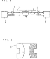
- Fig. 1 is a longitudinal sectional view of a frame damper according to the present invention;
- Fig.2 is a longitudinal sectional view of a conventional push-up type damper;
- Fig.3 is a longitudinal sectional view of a conventional push-up type damper having a hollow-curved supporting portion in the direction vertical to the conventional disk surface;
- Fig. 4 is a longitudinal sectional view of a conventional mechanical chassis supported by a damper; and
- Fig.5 is a longitudinal sectional view of an installing type damper without using a conventional fixing pin.
- For the above described reasons, the present invention employs a high elastic body with E value more than 1.176 × 10⁹ N/m2 (1.2 × 10⁴ kg/cm2) as the high elastic body to be used for a body frame which supports a mechanical chassis of optical disk equipment or the like, while the invention also employs an elastic body with a dynamic elastic modulus (hereinafter referred to as E value) less than 9.8 × 10⁸ N/m2 (1.0 x 10⁴kg/cm2) which aims at vibration damping and with rubber hardness JIS-A Class less than 70 as a low elastic body to be used for an installing portion of the mechanical chassis. By integral-molding both the low and high elastic bodies, a frame damper is formed. Further, it is more effective and desirable for damping vibration of a device to employ materials of high internal damping characteristics where the high elastic body has loss factor of tan δ more than 0.01 and the low elastic body has loss factor of tan δ more than 0.3. As an elastic body for forming a frame damper, thermoplastic material or thermosetting material may be used, while the frame damper may be manufactured by well known processes, such as processes of bonding the low elastic body and the high elastic body together after molding them respectively by a metal mold or of molding either the low elastic body or the high elastic body by a metal mold first and then inserting it into the metal mold of the other remaining elastic body and/or of combined-molding by injection molding.
- As materials of the low elastic body, elastomers having E value less than 9.8×10⁸N/m2(1.0 x 104kg/cm2) such as styrene series thermoplastic elastic, olefinic series thermoplastic elastomer, polyester series thermoplastic elastomer, urethane series thermoplastic elastomer, or the like can be used.
- As materials of the high elastic body, thermosetting resin such as said thermoplastic elastomer or polyethylene (PE), polypropylene (PP), polyvinyl chloride (PVC), polystyrene (PS), acrylonitrile-styrene acrylate resin (ASA), acrylonitrile-butadiene-styrene resin (ABS), polyamide (PA), polyacetal (POM), polycarbonate (PC), polyethylene terephthalate (PET), polybutylene terephthalate (PBT), polyphenylene oxide (PPO), polyphenylene sulfide (PPS), thermoplastic resin or phenol resin such as polyurethane (PUR), epoxy resin (EP), silicon resin (SI), polyurethane (PUR), epoxy resin (EP), silicon resin (SI), polyurethane (PUR), melamine resin (MF), polyester resin (UP), and so on can be used.
- By the frame damper according to the present invention, vibration isolation effect in the direction vertical to the disk surface can be identical with the vibration isolation effect of the conventional damper, and vibration in the direction parallel to the disk surface can be suppressed. Because the low elastic body reduces the natural frequency of the damper, the effect can be attained by utilizing a rubber-like elastic body having an E value less than 9.8×10⁶N/m2 (1.0 x 10⁴kg/cm2).
- Also, by utilizing a high elastic body having tan δ more than 0.01, self-generating vibration can be reduced even inside the high elastic body and the effect of vibration control can be further increased.
- Furthermore, by reducing the rubber hardness of the low elastic body, it becomes possible to easily reduce its spring constant and to enhance the vibration isolation characteristics in the direction vertical to the disk surface without lowering the vibration control characteristics in the direction parallel to the disk surface.
- By employing thermoplastic materials of the low elastic body and the high elastic body, the damper according to the present invention can be formed by insert molding with an ordinary injection molding machine, or by two-colour molding by using a plurality of dies. The number of manufacturing steps can be reduced as a result of automation and labour-saving. When the mechanical chassis and the body frame are assembled, the working process time can be reduced to about one-tenth (from 60 seconds to 6 seconds) and the assembly work can be conducted effectively.
- Next, the present invention will be described in detail with reference to the embodiment as shown in Fig. 1.
- A low
elastic body 1 of an installing portion of amechanical chassis 2 to abody frame 5 is formed to a hollow cylindrical shape from a styrene group thermoplastic elastomer having JIS-A Hs = 40, E = 4.9 × 10⁶ N/m2 (50kg/cm2), tan δ = 0.35 in advance. Then, a high elastic body of thebody frame 5 which is made of PPE, E=1.96×10⁹ N/m2 (2.0 x 10⁴kg/cm2), but with three different kinds of tan δ=0.005, tan δ = 0.01 and tan δ = 0.05 is integral-molded by a metal mold wherein the low elastic body formed in advance is inserted, thereby making a frame damper. - In Fig. 1,
reference numeral 3 denotes a disk,reference numeral 4 denotes an optical pick-up, and reference numeral 7 denotes a rotation portion. - A test for vibration transmissibility in the direction vertical to the
disk 3 and an examination of mechanical run-out characteristics by measuring the acceleration (G value) in the direction parallel to thedisk 3 were conducted. - As a comparative example, the same test was conducted by using a similar shape as shown in Fig. 3. As a material, butyl rubber was used.
- As a condition for the vibration test, a mechanical chassis of 120g was supported by frame dampers at four points and was excited at a frequency of 100Hz at which the disk is resonated. Acceleration on the mechanical chassis to the excitation acceleration of the vibration was measured and the acceleration on the mechanical chassis to the excitation acceleration of the vibration was obtained as a ratio (%). The result is shown in Table 1.
- In vibration transmissibility in the direction vertical to the disk, that of the comparative example is identical with that of
embodiments embodiment 4, as the hardness of the low elastic body is reduced to 30°, the natural frequency is reduced and, as a result, the vibration transmissibility is also reduced and the vibration isolation effect is improved. - As for measurement of a mechanical run-out by G value in the direction parallel to the disk, since a spring constant in the direction parallel to the disk is not enough in the case of the conventional shape of the comparative example, the G value becomes large, thereby causing mechanical run-out. In the
embodiment 1, since a spring constant in the direction parallel to the disk is obtained, the G value can be reduced to one third of the conventional damper shape. In theembodiments - Although various embodiments of the present invention have been described above in detail, the frame damper of the present invention can take various shapes according to installing methods or shapes required according to circumstances.
Table 1 Comparative Ex. Embodiment 1Embodiment 2Embodiment 3Embodiment 4Hardness of a low elastic body 4 0 4 0 4 0 4 0 3 0 High elstic body tan δ -- 0.005 0.01 0.05 0.05 Vibration transmissibility (%) 10 1 0 1 0 1 0 5 G value in the parallel direction with a disk 2 0.7 0.5 0.4 0.4
Claims (4)
- A frame damper for a rotating disk device, the frame damper comprising:a body frame (5); andan installing portion (1) connected to said body frame (5);said rotating disk device further comprising:a mechanical chassis (2) connected to said installing portion (1);a rotating portion (7) connected to said mechanical chassis (2); anda disk (3) connected to said rotating portion (7) and being rotatable by said rotating portion, said disk (3) being an optical disk or a magneto-optical disk;wherein said frame damper supports said mechanical chassis (2) connected with said rotating portion (7) and said disk (3) for media of a device for storing data into or reading data from a disk information medium by a non-contact device and an optical transmitter or an optical receiver; characterised in thatsaid body frame (5) is a high elastic body, said installing portion (1) is a low elastic body, and a composition of the high elastic body and the low elastic body reduce vibration of the disk (3);said body frame is made of a resin-like elastic body, said body frame having a dynamic elastic modulus greater than 1.17 6 x 10⁹ N/m2 (1.2 × 10⁴ kg/cm2); andsaid installing portion is made of a rubber-like elastic body, said installing portion having a dynamic elastic modulus less than 9.8 x 10⁸ N/m2 (1.0 x 10⁴kg/cm2).
- A frame damper as claimed in claim 1, characterized in that said installing portion (1) is formed of thermoplastic material, and said body frame (5) is formed of thermosetting or thermoplastic material.
- A frame damper as claimed in claim 1 or 2, characterized in that a non-contact device (4) reading information from said disk (3) is connected to said chassis (2).
- A frame damper as claimed in claim 1, characterized in that
said installing portion (1) is formed of thermoplastic material;
said body frame (5) is formed of thermosetting or thermoplastic material;
a non-contact device (4) reading information from said disk (3) is connected to said chassis (2); and
said disk (3) is an optical disk or a magneto-optical disk.
Applications Claiming Priority (2)
| Application Number | Priority Date | Filing Date | Title |
|---|---|---|---|
| JP9051094A JPH10231893A (en) | 1997-02-20 | 1997-02-20 | Frame damper |
| JP51094/97 | 1997-02-20 |
Publications (3)
| Publication Number | Publication Date |
|---|---|
| EP0860833A2 EP0860833A2 (en) | 1998-08-26 |
| EP0860833A3 EP0860833A3 (en) | 1998-09-09 |
| EP0860833B1 true EP0860833B1 (en) | 2006-04-26 |
Family
ID=12877239
Family Applications (1)
| Application Number | Title | Priority Date | Filing Date |
|---|---|---|---|
| EP98301277A Expired - Lifetime EP0860833B1 (en) | 1997-02-20 | 1998-02-20 | Frame damper |
Country Status (6)
| Country | Link |
|---|---|
| US (1) | US6045113A (en) |
| EP (1) | EP0860833B1 (en) |
| JP (1) | JPH10231893A (en) |
| KR (1) | KR100523364B1 (en) |
| DE (1) | DE69834287T2 (en) |
| TW (1) | TW422969B (en) |
Families Citing this family (48)
| Publication number | Priority date | Publication date | Assignee | Title |
|---|---|---|---|---|
| JPH10231893A (en) * | 1997-02-20 | 1998-09-02 | Polymertech Kk | Frame damper |
| CN1677551A (en) | 2000-03-01 | 2005-10-05 | 松下电器产业株式会社 | Disk device |
| JP4347515B2 (en) * | 2000-11-27 | 2009-10-21 | ポリマテック株式会社 | Anti-vibration damper integrated mechanical chassis |
| DE10131424A1 (en) * | 2001-06-29 | 2003-01-09 | Conti Temic Microelectronic | Housing for an electrical assembly with an acceleration sensor |
| JP4271606B2 (en) * | 2004-03-16 | 2009-06-03 | オリオン電機株式会社 | Disk unit |
| JP2005276242A (en) * | 2004-03-22 | 2005-10-06 | Pioneer Electronic Corp | Disk drive unit |
| KR100594288B1 (en) | 2004-07-14 | 2006-06-30 | 삼성전자주식회사 | Shock-absorbing member and hard disc drive therewith |
| KR100582950B1 (en) | 2004-07-23 | 2006-05-25 | 삼성전자주식회사 | Vibration preventing device and optical disc drive having the same |
| JP4317574B2 (en) * | 2005-04-12 | 2009-08-19 | パナソニック株式会社 | Disk unit |
| JP2006302438A (en) * | 2005-04-22 | 2006-11-02 | Matsushita Electric Ind Co Ltd | Optical disk drive |
| JP2007113622A (en) * | 2005-10-19 | 2007-05-10 | Tanashin Denki Co | Oil damper |
| US8549912B2 (en) * | 2007-12-18 | 2013-10-08 | Teradyne, Inc. | Disk drive transport, clamping and testing |
| US7996174B2 (en) * | 2007-12-18 | 2011-08-09 | Teradyne, Inc. | Disk drive testing |
| US8305751B2 (en) | 2008-04-17 | 2012-11-06 | Teradyne, Inc. | Vibration isolation within disk drive testing systems |
| US7848106B2 (en) * | 2008-04-17 | 2010-12-07 | Teradyne, Inc. | Temperature control within disk drive testing systems |
| US8102173B2 (en) | 2008-04-17 | 2012-01-24 | Teradyne, Inc. | Thermal control system for test slot of test rack for disk drive testing system with thermoelectric device and a cooling conduit |
| US8238099B2 (en) | 2008-04-17 | 2012-08-07 | Teradyne, Inc. | Enclosed operating area for disk drive testing systems |
| US8117480B2 (en) * | 2008-04-17 | 2012-02-14 | Teradyne, Inc. | Dependent temperature control within disk drive testing systems |
| US7945424B2 (en) * | 2008-04-17 | 2011-05-17 | Teradyne, Inc. | Disk drive emulator and method of use thereof |
| US8041449B2 (en) * | 2008-04-17 | 2011-10-18 | Teradyne, Inc. | Bulk feeding disk drives to disk drive testing systems |
| US8095234B2 (en) | 2008-04-17 | 2012-01-10 | Teradyne, Inc. | Transferring disk drives within disk drive testing systems |
| US20090262455A1 (en) | 2008-04-17 | 2009-10-22 | Teradyne, Inc. | Temperature Control Within Disk Drive Testing Systems |
| US8160739B2 (en) | 2008-04-17 | 2012-04-17 | Teradyne, Inc. | Transferring storage devices within storage device testing systems |
| CN102112887B (en) | 2008-06-03 | 2015-06-10 | 泰拉丁公司 | Processing storage devices |
| US8547123B2 (en) | 2009-07-15 | 2013-10-01 | Teradyne, Inc. | Storage device testing system with a conductive heating assembly |
| US7920380B2 (en) | 2009-07-15 | 2011-04-05 | Teradyne, Inc. | Test slot cooling system for a storage device testing system |
| US8466699B2 (en) | 2009-07-15 | 2013-06-18 | Teradyne, Inc. | Heating storage devices in a testing system |
| US8687356B2 (en) | 2010-02-02 | 2014-04-01 | Teradyne, Inc. | Storage device testing system cooling |
| US8116079B2 (en) | 2009-07-15 | 2012-02-14 | Teradyne, Inc. | Storage device testing system cooling |
| US7995349B2 (en) * | 2009-07-15 | 2011-08-09 | Teradyne, Inc. | Storage device temperature sensing |
| US8628239B2 (en) | 2009-07-15 | 2014-01-14 | Teradyne, Inc. | Storage device temperature sensing |
| US9779780B2 (en) | 2010-06-17 | 2017-10-03 | Teradyne, Inc. | Damping vibrations within storage device testing systems |
| US8687349B2 (en) | 2010-07-21 | 2014-04-01 | Teradyne, Inc. | Bulk transfer of storage devices using manual loading |
| US9001456B2 (en) | 2010-08-31 | 2015-04-07 | Teradyne, Inc. | Engaging test slots |
| US9459312B2 (en) | 2013-04-10 | 2016-10-04 | Teradyne, Inc. | Electronic assembly test system |
| DE102013018185A1 (en) * | 2013-10-30 | 2015-04-30 | Carl Freudenberg Kg | camp |
| CN104565192B (en) * | 2015-01-12 | 2016-01-13 | 华北水利水电大学 | Bran finisher double tunning mass damper, compound subtract isolation mounting and implementation method |
| US10725091B2 (en) | 2017-08-28 | 2020-07-28 | Teradyne, Inc. | Automated test system having multiple stages |
| US10845410B2 (en) | 2017-08-28 | 2020-11-24 | Teradyne, Inc. | Automated test system having orthogonal robots |
| US11226390B2 (en) | 2017-08-28 | 2022-01-18 | Teradyne, Inc. | Calibration process for an automated test system |
| US10948534B2 (en) | 2017-08-28 | 2021-03-16 | Teradyne, Inc. | Automated test system employing robotics |
| US10983145B2 (en) | 2018-04-24 | 2021-04-20 | Teradyne, Inc. | System for testing devices inside of carriers |
| US10775408B2 (en) | 2018-08-20 | 2020-09-15 | Teradyne, Inc. | System for testing devices inside of carriers |
| US11953519B2 (en) | 2020-10-22 | 2024-04-09 | Teradyne, Inc. | Modular automated test system |
| US11867749B2 (en) | 2020-10-22 | 2024-01-09 | Teradyne, Inc. | Vision system for an automated test system |
| US11899042B2 (en) | 2020-10-22 | 2024-02-13 | Teradyne, Inc. | Automated test system |
| US11754622B2 (en) | 2020-10-22 | 2023-09-12 | Teradyne, Inc. | Thermal control system for an automated test system |
| US11754596B2 (en) | 2020-10-22 | 2023-09-12 | Teradyne, Inc. | Test site configuration in an automated test system |
Family Cites Families (30)
| Publication number | Priority date | Publication date | Assignee | Title |
|---|---|---|---|---|
| DE1020994B (en) * | 1957-12-19 | |||
| GB452858A (en) * | 1934-09-26 | 1936-08-27 | Hugh Compton Lord | Improvements in vibration insulating joints or mountings |
| US2088566A (en) * | 1935-02-07 | 1937-08-03 | L C Smith & Corona Typewriters | Machine support |
| US2302579A (en) * | 1940-08-17 | 1942-11-17 | Francis J Shields | Slipper |
| US2520757A (en) * | 1946-06-15 | 1950-08-29 | Wilcox Gay Corp | Phonograph-shock and vibration absorbing support |
| BE815016A (en) * | 1973-05-16 | 1974-11-14 | X-RAY EXAMINATION DEVICE | |
| GB1473314A (en) * | 1974-06-03 | 1977-05-11 | Ard Anstalt | Record playing decks |
| US4385025A (en) * | 1979-10-22 | 1983-05-24 | Barry Wright Corporation | Method of coinjection molding of thermoplastic and thermoplastic elastomer |
| IL61216A (en) * | 1979-10-22 | 1985-06-30 | Wright Barry Corp | Vibration isolator and its manufacture |
| US4369950A (en) * | 1980-05-27 | 1983-01-25 | Complete Business Services Corp. | Turntable support |
| DE3026766A1 (en) * | 1980-07-15 | 1982-01-28 | Hans 8898 Schrobenhausen Sorcan | VIBRATED SYSTEM AGAINST BODY SOUND AGAINST A RIGID MOUNT |
| US4687173A (en) * | 1984-02-17 | 1987-08-18 | Genna Robert T | Mechanical and acoustical vibration reduction apparatus for turntables and speaker enclosures |
| JPS60163592U (en) * | 1984-04-07 | 1985-10-30 | ソニー株式会社 | Vehicle optical disc player |
| FR2565395B1 (en) * | 1984-05-29 | 1989-05-26 | Philips Ind Commerciale | DEVICE FOR FAST MOUNTING OF A PLATE ON A CHASSIS, ESPECIALLY FOR A RECORDER |
| JPH0249038Y2 (en) * | 1984-10-11 | 1990-12-21 | ||
| US4718631A (en) * | 1984-10-26 | 1988-01-12 | Barry Wright Corporation | Foot isolating |
| JPS6186845U (en) * | 1984-11-10 | 1986-06-06 | ||
| JPS61132589U (en) * | 1985-02-04 | 1986-08-19 | ||
| JP2718665B2 (en) * | 1986-07-09 | 1998-02-25 | 株式会社日立製作所 | File storage |
| WO1988006335A1 (en) * | 1987-02-12 | 1988-08-25 | Dai Nippon Insatsu Kabushiki Kaisha | Data recording/reproducing apparatus for optical card |
| US5174540A (en) * | 1989-02-21 | 1992-12-29 | Bristol Compressors | Vibration isolating mounting grommet |
| DE3933251A1 (en) * | 1989-10-05 | 1991-04-11 | Continental Ag | Shock bearing for small weighted sensitive instruments - has spring elements of different thicknesses, stop plate and counter step |
| JPH03197024A (en) * | 1989-12-26 | 1991-08-28 | Yokohama Rubber Co Ltd:The | Processing of vibration damper with thermosetting restraining layer |
| US5096153A (en) * | 1990-10-19 | 1992-03-17 | Onan Corporation | Shock and vibration mount |
| JP3298213B2 (en) * | 1993-03-17 | 2002-07-02 | 日産自動車株式会社 | Anti-vibration pad |
| JPH0673484U (en) * | 1993-03-30 | 1994-10-18 | 北辰工業株式会社 | Damper |
| JPH0680935U (en) * | 1993-04-30 | 1994-11-15 | 北辰工業株式会社 | Damper |
| JP2899777B2 (en) * | 1993-07-20 | 1999-06-02 | 有限会社特殊ゴム研究所 | Anti-vibration support device |
| GB9512752D0 (en) * | 1995-06-22 | 1995-08-23 | Audio Partnership Limited | Isolating platform |
| JPH10231893A (en) * | 1997-02-20 | 1998-09-02 | Polymertech Kk | Frame damper |
-
1997
- 1997-02-20 JP JP9051094A patent/JPH10231893A/en active Pending
-
1998
- 1998-01-22 TW TW087100882A patent/TW422969B/en active
- 1998-02-05 US US09/019,235 patent/US6045113A/en not_active Expired - Fee Related
- 1998-02-16 KR KR10-1998-0004622A patent/KR100523364B1/en not_active IP Right Cessation
- 1998-02-20 DE DE69834287T patent/DE69834287T2/en not_active Expired - Lifetime
- 1998-02-20 EP EP98301277A patent/EP0860833B1/en not_active Expired - Lifetime
Also Published As
| Publication number | Publication date |
|---|---|
| KR19980071392A (en) | 1998-10-26 |
| DE69834287T2 (en) | 2007-04-26 |
| EP0860833A3 (en) | 1998-09-09 |
| US6045113A (en) | 2000-04-04 |
| TW422969B (en) | 2001-02-21 |
| DE69834287D1 (en) | 2006-06-01 |
| EP0860833A2 (en) | 1998-08-26 |
| JPH10231893A (en) | 1998-09-02 |
| KR100523364B1 (en) | 2005-12-27 |
Similar Documents
| Publication | Publication Date | Title |
|---|---|---|
| EP0860833B1 (en) | Frame damper | |
| KR100509296B1 (en) | Anisotropic damper | |
| US7440274B2 (en) | Digital storage element mechanical shock isolation arrangement in a host device and method | |
| US6809898B1 (en) | Disk drive rocking mode vibration damper | |
| EP1471534B1 (en) | Shock-absorbing member, shock-absorbing method of electronic device employing the member and electronic device adapting the member and the method | |
| GB2326968A (en) | A damper for a voice coil motor in a hard disk drive | |
| KR20020013199A (en) | The de-vibration rubber for disk drive | |
| US6205111B1 (en) | Disk driving apparatus for reliably centering a meter-layer optical disk on which information is recorded | |
| US5602697A (en) | Apparatus for fixing a spindle motor to a hard disk drive base | |
| KR100530685B1 (en) | Supporting structure of floating chassis of disk apparatus | |
| US3997174A (en) | Turntable mat | |
| US7310223B2 (en) | Electrical connector device for a disc drive | |
| US5645262A (en) | Portable CD mount for off road vehicles | |
| CN1725363B (en) | Vibration preventing device and an optical disc drive having the same | |
| US4796141A (en) | Disc assembly for a magnetic disc apparatus | |
| KR0158854B1 (en) | A disk chucking device for clamper of cdp | |
| EP0860832A3 (en) | Disc drive | |
| JP2000081070A (en) | Liquid filled damper for impact detector and its manufacture | |
| MY109997A (en) | Turntable for disc-shaped information carriers. | |
| JPH0864665A (en) | Substrate container and transferring method for substrate | |
| JP2916748B2 (en) | Anti-vibration support device | |
| CN1455931A (en) | Disk board holder and transport case | |
| JPH05303877A (en) | Optical disk device | |
| CN1674122A (en) | CD driving device set with pick up device protection part |
Legal Events
| Date | Code | Title | Description |
|---|---|---|---|
| PUAI | Public reference made under article 153(3) epc to a published international application that has entered the european phase |
Free format text: ORIGINAL CODE: 0009012 |
|
| PUAL | Search report despatched |
Free format text: ORIGINAL CODE: 0009013 |
|
| AK | Designated contracting states |
Kind code of ref document: A2 Designated state(s): DE NL |
|
| AX | Request for extension of the european patent |
Free format text: AL;LT;LV;MK;RO;SI |
|
| AK | Designated contracting states |
Kind code of ref document: A3 Designated state(s): AT BE CH DE DK ES FI FR GB GR IE IT LI LU MC NL PT SE |
|
| AX | Request for extension of the european patent |
Free format text: AL;LT;LV;MK;RO;SI |
|
| 17P | Request for examination filed |
Effective date: 19990205 |
|
| AKX | Designation fees paid |
Free format text: DE NL |
|
| RBV | Designated contracting states (corrected) |
Designated state(s): DE NL |
|
| 17Q | First examination report despatched |
Effective date: 20010213 |
|
| GRAP | Despatch of communication of intention to grant a patent |
Free format text: ORIGINAL CODE: EPIDOSNIGR1 |
|
| GRAS | Grant fee paid |
Free format text: ORIGINAL CODE: EPIDOSNIGR3 |
|
| GRAA | (expected) grant |
Free format text: ORIGINAL CODE: 0009210 |
|
| AK | Designated contracting states |
Kind code of ref document: B1 Designated state(s): DE NL |
|
| REF | Corresponds to: |
Ref document number: 69834287 Country of ref document: DE Date of ref document: 20060601 Kind code of ref document: P |
|
| PLBE | No opposition filed within time limit |
Free format text: ORIGINAL CODE: 0009261 |
|
| STAA | Information on the status of an ep patent application or granted ep patent |
Free format text: STATUS: NO OPPOSITION FILED WITHIN TIME LIMIT |
|
| 26N | No opposition filed |
Effective date: 20070129 |
|
| PGFP | Annual fee paid to national office [announced via postgrant information from national office to epo] |
Ref country code: DE Payment date: 20100303 Year of fee payment: 13 |
|
| PGFP | Annual fee paid to national office [announced via postgrant information from national office to epo] |
Ref country code: NL Payment date: 20100209 Year of fee payment: 13 |
|
| REG | Reference to a national code |
Ref country code: NL Ref legal event code: V1 Effective date: 20110901 |
|
| PG25 | Lapsed in a contracting state [announced via postgrant information from national office to epo] |
Ref country code: NL Free format text: LAPSE BECAUSE OF NON-PAYMENT OF DUE FEES Effective date: 20110901 |
|
| REG | Reference to a national code |
Ref country code: DE Ref legal event code: R119 Ref document number: 69834287 Country of ref document: DE Effective date: 20110901 |
|
| PG25 | Lapsed in a contracting state [announced via postgrant information from national office to epo] |
Ref country code: DE Free format text: LAPSE BECAUSE OF NON-PAYMENT OF DUE FEES Effective date: 20110901 |