EP0861378B1 - Mechanical repair for a honeycomb panel - Google Patents
Mechanical repair for a honeycomb panel Download PDFInfo
- Publication number
- EP0861378B1 EP0861378B1 EP96932303A EP96932303A EP0861378B1 EP 0861378 B1 EP0861378 B1 EP 0861378B1 EP 96932303 A EP96932303 A EP 96932303A EP 96932303 A EP96932303 A EP 96932303A EP 0861378 B1 EP0861378 B1 EP 0861378B1
- Authority
- EP
- European Patent Office
- Prior art keywords
- skin
- bolt
- sleeve
- exterior
- panel
- Prior art date
- Legal status (The legal status is an assumption and is not a legal conclusion. Google has not performed a legal analysis and makes no representation as to the accuracy of the status listed.)
- Expired - Lifetime
Links
- 230000008439 repair process Effects 0.000 title description 6
- 238000000034 method Methods 0.000 claims description 35
- 230000003014 reinforcing effect Effects 0.000 claims description 12
- 239000011162 core material Substances 0.000 description 54
- 229910052751 metal Inorganic materials 0.000 description 7
- 239000002184 metal Substances 0.000 description 7
- 238000005553 drilling Methods 0.000 description 5
- 239000000463 material Substances 0.000 description 5
- 230000032798 delamination Effects 0.000 description 4
- 238000003466 welding Methods 0.000 description 3
- 239000011152 fibreglass Substances 0.000 description 2
- 239000004033 plastic Substances 0.000 description 2
- 229910000838 Al alloy Inorganic materials 0.000 description 1
- 241000277284 Salvelinus fontinalis Species 0.000 description 1
- 229910000831 Steel Inorganic materials 0.000 description 1
- 229910001069 Ti alloy Inorganic materials 0.000 description 1
- RTAQQCXQSZGOHL-UHFFFAOYSA-N Titanium Chemical compound [Ti] RTAQQCXQSZGOHL-UHFFFAOYSA-N 0.000 description 1
- 239000004411 aluminium Substances 0.000 description 1
- 229910052782 aluminium Inorganic materials 0.000 description 1
- XAGFODPZIPBFFR-UHFFFAOYSA-N aluminium Chemical compound [Al] XAGFODPZIPBFFR-UHFFFAOYSA-N 0.000 description 1
- 230000015556 catabolic process Effects 0.000 description 1
- 238000004140 cleaning Methods 0.000 description 1
- 230000003749 cleanliness Effects 0.000 description 1
- 238000010276 construction Methods 0.000 description 1
- 238000006731 degradation reaction Methods 0.000 description 1
- 238000003780 insertion Methods 0.000 description 1
- 230000037431 insertion Effects 0.000 description 1
- 238000009434 installation Methods 0.000 description 1
- 230000000149 penetrating effect Effects 0.000 description 1
- 230000002787 reinforcement Effects 0.000 description 1
- 238000005476 soldering Methods 0.000 description 1
- 239000007787 solid Substances 0.000 description 1
- 239000004071 soot Substances 0.000 description 1
- 125000006850 spacer group Chemical group 0.000 description 1
- 238000010561 standard procedure Methods 0.000 description 1
- 239000010959 steel Substances 0.000 description 1
- 239000010936 titanium Substances 0.000 description 1
- 229910052719 titanium Inorganic materials 0.000 description 1
- 239000002023 wood Substances 0.000 description 1
Images


Classifications
-
- F—MECHANICAL ENGINEERING; LIGHTING; HEATING; WEAPONS; BLASTING
- F16—ENGINEERING ELEMENTS AND UNITS; GENERAL MEASURES FOR PRODUCING AND MAINTAINING EFFECTIVE FUNCTIONING OF MACHINES OR INSTALLATIONS; THERMAL INSULATION IN GENERAL
- F16B—DEVICES FOR FASTENING OR SECURING CONSTRUCTIONAL ELEMENTS OR MACHINE PARTS TOGETHER, e.g. NAILS, BOLTS, CIRCLIPS, CLAMPS, CLIPS OR WEDGES; JOINTS OR JOINTING
- F16B5/00—Joining sheets or plates, e.g. panels, to one another or to strips or bars parallel to them
- F16B5/01—Joining sheets or plates, e.g. panels, to one another or to strips or bars parallel to them by means of fastening elements specially adapted for honeycomb panels
-
- Y—GENERAL TAGGING OF NEW TECHNOLOGICAL DEVELOPMENTS; GENERAL TAGGING OF CROSS-SECTIONAL TECHNOLOGIES SPANNING OVER SEVERAL SECTIONS OF THE IPC; TECHNICAL SUBJECTS COVERED BY FORMER USPC CROSS-REFERENCE ART COLLECTIONS [XRACs] AND DIGESTS
- Y10—TECHNICAL SUBJECTS COVERED BY FORMER USPC
- Y10T—TECHNICAL SUBJECTS COVERED BY FORMER US CLASSIFICATION
- Y10T29/00—Metal working
- Y10T29/49—Method of mechanical manufacture
- Y10T29/49616—Structural member making
- Y10T29/49623—Static structure, e.g., a building component
- Y10T29/49629—Panel
-
- Y—GENERAL TAGGING OF NEW TECHNOLOGICAL DEVELOPMENTS; GENERAL TAGGING OF CROSS-SECTIONAL TECHNOLOGIES SPANNING OVER SEVERAL SECTIONS OF THE IPC; TECHNICAL SUBJECTS COVERED BY FORMER USPC CROSS-REFERENCE ART COLLECTIONS [XRACs] AND DIGESTS
- Y10—TECHNICAL SUBJECTS COVERED BY FORMER USPC
- Y10T—TECHNICAL SUBJECTS COVERED BY FORMER US CLASSIFICATION
- Y10T29/00—Metal working
- Y10T29/49—Method of mechanical manufacture
- Y10T29/49718—Repairing
- Y10T29/49732—Repairing by attaching repair preform, e.g., remaking, restoring, or patching
- Y10T29/49739—Mechanically attaching preform by separate fastener
- Y10T29/49741—Screw threaded fastener
-
- Y—GENERAL TAGGING OF NEW TECHNOLOGICAL DEVELOPMENTS; GENERAL TAGGING OF CROSS-SECTIONAL TECHNOLOGIES SPANNING OVER SEVERAL SECTIONS OF THE IPC; TECHNICAL SUBJECTS COVERED BY FORMER USPC CROSS-REFERENCE ART COLLECTIONS [XRACs] AND DIGESTS
- Y10—TECHNICAL SUBJECTS COVERED BY FORMER USPC
- Y10T—TECHNICAL SUBJECTS COVERED BY FORMER US CLASSIFICATION
- Y10T29/00—Metal working
- Y10T29/49—Method of mechanical manufacture
- Y10T29/49826—Assembling or joining
- Y10T29/49908—Joining by deforming
- Y10T29/49938—Radially expanding part in cavity, aperture, or hollow body
- Y10T29/4994—Radially expanding internal tube
-
- Y—GENERAL TAGGING OF NEW TECHNOLOGICAL DEVELOPMENTS; GENERAL TAGGING OF CROSS-SECTIONAL TECHNOLOGIES SPANNING OVER SEVERAL SECTIONS OF THE IPC; TECHNICAL SUBJECTS COVERED BY FORMER USPC CROSS-REFERENCE ART COLLECTIONS [XRACs] AND DIGESTS
- Y10—TECHNICAL SUBJECTS COVERED BY FORMER USPC
- Y10T—TECHNICAL SUBJECTS COVERED BY FORMER US CLASSIFICATION
- Y10T29/00—Metal working
- Y10T29/49—Method of mechanical manufacture
- Y10T29/49826—Assembling or joining
- Y10T29/49947—Assembling or joining by applying separate fastener
- Y10T29/49948—Multipart cooperating fastener [e.g., bolt and nut]
-
- Y—GENERAL TAGGING OF NEW TECHNOLOGICAL DEVELOPMENTS; GENERAL TAGGING OF CROSS-SECTIONAL TECHNOLOGIES SPANNING OVER SEVERAL SECTIONS OF THE IPC; TECHNICAL SUBJECTS COVERED BY FORMER USPC CROSS-REFERENCE ART COLLECTIONS [XRACs] AND DIGESTS
- Y10—TECHNICAL SUBJECTS COVERED BY FORMER USPC
- Y10T—TECHNICAL SUBJECTS COVERED BY FORMER US CLASSIFICATION
- Y10T403/00—Joints and connections
- Y10T403/49—Member deformed in situ
- Y10T403/4924—Inner member is expanded by longitudinally inserted element
-
- Y—GENERAL TAGGING OF NEW TECHNOLOGICAL DEVELOPMENTS; GENERAL TAGGING OF CROSS-SECTIONAL TECHNOLOGIES SPANNING OVER SEVERAL SECTIONS OF THE IPC; TECHNICAL SUBJECTS COVERED BY FORMER USPC CROSS-REFERENCE ART COLLECTIONS [XRACs] AND DIGESTS
- Y10—TECHNICAL SUBJECTS COVERED BY FORMER USPC
- Y10T—TECHNICAL SUBJECTS COVERED BY FORMER US CLASSIFICATION
- Y10T403/00—Joints and connections
- Y10T403/49—Member deformed in situ
- Y10T403/4958—Separate deforming means remains with joint assembly
-
- Y—GENERAL TAGGING OF NEW TECHNOLOGICAL DEVELOPMENTS; GENERAL TAGGING OF CROSS-SECTIONAL TECHNOLOGIES SPANNING OVER SEVERAL SECTIONS OF THE IPC; TECHNICAL SUBJECTS COVERED BY FORMER USPC CROSS-REFERENCE ART COLLECTIONS [XRACs] AND DIGESTS
- Y10—TECHNICAL SUBJECTS COVERED BY FORMER USPC
- Y10T—TECHNICAL SUBJECTS COVERED BY FORMER US CLASSIFICATION
- Y10T403/00—Joints and connections
- Y10T403/49—Member deformed in situ
- Y10T403/4966—Deformation occurs simultaneously with assembly
-
- Y—GENERAL TAGGING OF NEW TECHNOLOGICAL DEVELOPMENTS; GENERAL TAGGING OF CROSS-SECTIONAL TECHNOLOGIES SPANNING OVER SEVERAL SECTIONS OF THE IPC; TECHNICAL SUBJECTS COVERED BY FORMER USPC CROSS-REFERENCE ART COLLECTIONS [XRACs] AND DIGESTS
- Y10—TECHNICAL SUBJECTS COVERED BY FORMER USPC
- Y10T—TECHNICAL SUBJECTS COVERED BY FORMER US CLASSIFICATION
- Y10T403/00—Joints and connections
- Y10T403/71—Rod side to plate or side
- Y10T403/7123—Traversed by connector
Landscapes
- Engineering & Computer Science (AREA)
- General Engineering & Computer Science (AREA)
- Mechanical Engineering (AREA)
- Laminated Bodies (AREA)
- Connection Of Plates (AREA)
Description
| PATENT NO | INVENTOR | TITLE |
| 3076668 | Famely | Fittings for Retaining Cylindrical Members in Place |
| 3468091 | Gerhard | Wall Fasteners |
| 3526072 | Campbell | Load Distributing System for Panels Incorporating Honeycomb Core |
| 4048898 | Salter | Fastener for Multi Metal Stack-Ups |
| 4089247 | Dahl et al | Blind Fastener |
| 4499647 | Sakamura et al | Blind Nut Fastening Method |
| 4656806 | Leibhard et al | Expansion Anchor Assembly |
| 4717612 | Shakelford | Fasteners for Honeycomb Structures |
| 4934861 | Weeks et al | Attachment Apparatus for External Stores On Thin-Wall Poles |
| 5040917 | Camuffo | Device for Fixing Mechanical Parts to the Body of a Motor Vehicle |
| 5205689 | Fischer | Expansible Plug |
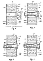
characterised by providing that the panel has an intermediate skin and the core means comprises first and second cores which separate the first and second skins from the intermediate skin, and characterised by the steps of;
Claims (6)
- A method of reinforcing a sandwich panel (10), the panel having first and second exterior skins (14, 16) separated by core means (12A, 12B) the exterior skins (14, 16) each having an external surface and an internal surface, comprising(1) boring an in-line hole through the panel (10) to penetrate the first and second exterior skins (14, 16) and the core means (12A, 12B) providing a hole in the first and second exterior skins to a diameter A;
characterised by providing that the panel has an intermediate skin (60) and the core means comprises first and second cores (12A, 12B) which separate the first and second skins (14, 16) from the intermediate skin (60), and characterised by the steps of;(2) enlarging the hole in said first and second exterior skins (14, 16) to a diameter B;(3) inserting a first tubular sleeve (24A) into said hole in said first exterior skin (14), the first sleeve (24A) having a first end and a second end and a length substantially equal to the spacing between said first exterior skin (14) and said intermediate skin (60);(4) inserting a second tubular sleeve (24B) into said hole in said second exterior skin (16), the second sleeve (24B) having a first end and a second end and a length substantially equal to the spacing between said second exterior skin (16) and said intermediate skin (60), the second sleeve (24B) being in axial alignment with said first sleeve (24A), the first and second sleeves (24A, 24B) having a diameter greater than A and slightly less than B, the first end of each of the sleeves (24A, 24B) contacting a surface of said intermediate skin (60); and(5) flaring said second end of each of said first and second sleeves (24A, 24B) to an external diameter greater than B, said second end of each of said sleeves (24A, 24B) contacting respectively said inner surfaces of said first and second exterior skins (14, 16). - The method according to claim 1 including:(5) inserting a bolt (68) through said tubular sleeves (24A, 24B), the bolt (68) having a head (72) of diameter greater than B, and the head (72) contacting said exterior surface of said first exterior skin (14); and(6) installing a nut (70) on said bolt (68) to contact said exterior surface of said second exterior skin (16).
- The method according to claim 2 wherein the step of flaring said second end of each of said first and second sleeves (24A, 24B) includes positioning on said bolt (68) first and second flare washers (50A, 50B), one adjacent said bolt head (72) engaging said first tubular sleeve second end and one adjacent said nut (70) engaging said second tubular sleeve second end.
- The method according to claim 1 wherein step (5) comprises inserting a bolt (34, 50) into said aligned tubular sleeves (24A, 24B), the bolt having an enlarged diameter head (36, 58) and a frusto-conical portion (42, 54) adjacent the head, followed by installing a nut (46) on said bolt (34, 50), and tightening the nut (46) on said bolt (34, 58) to cause said frusto-conical portion (42, 54) to flare said second end of said first sleeve (14).
- The method according to claim 4 wherein said frusto-conical portion (54) is removably positionable on said bolt (50).
- The method according to claim 5 wherein said frusto-conical portion (54) removably positionable on said bolt (50) includes an integral washer portion (52) that contacts said external surface of said first skin (14).
Applications Claiming Priority (3)
| Application Number | Priority Date | Filing Date | Title |
|---|---|---|---|
| US556708 | 1995-11-13 | ||
| US08/556,708 US5682678A (en) | 1995-11-13 | 1995-11-13 | Mechanical repair for a honeycomb panel |
| PCT/US1996/015172 WO1997018398A1 (en) | 1995-11-13 | 1996-09-23 | Mechanical repair for a honeycomb panel |
Publications (2)
| Publication Number | Publication Date |
|---|---|
| EP0861378A1 EP0861378A1 (en) | 1998-09-02 |
| EP0861378B1 true EP0861378B1 (en) | 2001-11-07 |
Family
ID=24222514
Family Applications (1)
| Application Number | Title | Priority Date | Filing Date |
|---|---|---|---|
| EP96932303A Expired - Lifetime EP0861378B1 (en) | 1995-11-13 | 1996-09-23 | Mechanical repair for a honeycomb panel |
Country Status (6)
| Country | Link |
|---|---|
| US (2) | US5682678A (en) |
| EP (1) | EP0861378B1 (en) |
| JP (1) | JP3847344B2 (en) |
| CA (1) | CA2236042C (en) |
| DE (1) | DE69616818T2 (en) |
| WO (1) | WO1997018398A1 (en) |
Families Citing this family (69)
| Publication number | Priority date | Publication date | Assignee | Title |
|---|---|---|---|---|
| DE69636148T2 (en) * | 1996-01-12 | 2007-03-01 | The Boeing Co., Chicago | Sandwich structures with several sheets and an integrated hardpoint |
| US6237304B1 (en) | 1997-07-18 | 2001-05-29 | Henkel Corporation | Laminate structural bulkhead |
| US6856974B1 (en) | 1998-02-02 | 2005-02-15 | Checkfree Corporation | Electronic bill presentment technique with enhanced biller control |
| US6404650B1 (en) * | 1998-12-11 | 2002-06-11 | International Business Machines Corporation | System for connecting a module comprising a plurality of electronic cards to a backplane |
| US6834469B2 (en) | 2001-01-24 | 2004-12-28 | Geotek, Inc. | Utility line support member |
| US6945728B2 (en) * | 2002-06-07 | 2005-09-20 | Orchid Automation, Llc | Mechanical fastener |
| FR2844926B1 (en) * | 2002-09-24 | 2006-11-03 | Framatome Connectors Int | FIXING AND CONTACT DEVICE FOR BUS BAR |
| US6874985B2 (en) * | 2002-12-04 | 2005-04-05 | Huck International, Inc. | Captive nut assembly |
| GB2414213B (en) * | 2004-05-21 | 2008-11-12 | Intelligent Engineering | Improved structural sandwich plate members |
| US8070994B2 (en) | 2004-06-18 | 2011-12-06 | Zephyros, Inc. | Panel structure |
| DE102004050399B4 (en) * | 2004-10-15 | 2007-03-01 | Airbus Deutschland Gmbh | Window element for insertion into a window opening in an outer skin of a means of transport, in particular of an aircraft |
| GB2419168B (en) * | 2004-10-18 | 2008-08-20 | Airbus Uk Ltd | A Fastener assembly |
| US7717659B2 (en) * | 2005-08-15 | 2010-05-18 | Acumet Intellectual Properties, Llc | Zero-clearance bolted joint |
| AU2005209605A1 (en) * | 2005-09-08 | 2007-03-22 | Vlaeberg Pty Ltd | Metal Roof Truss Connector Assembly |
| FR2891239B1 (en) * | 2005-09-28 | 2009-04-17 | Airbus France Sas | FLOOR PANEL AND INSTALLATION FOR FIXING BUILDING ELEMENTS COMPRISING SUCH PANELS |
| US20070237605A1 (en) * | 2005-10-13 | 2007-10-11 | Northern Hydraulic Cylinder Engineers Limited | Pin |
| US20070101679A1 (en) * | 2005-10-25 | 2007-05-10 | L&L Products, Inc. | Panel structure |
| US20100025147A1 (en) * | 2005-10-31 | 2010-02-04 | L&L Products, Inc. | Damping material, method of forming the damping material and method of using the damping material |
| US8484930B2 (en) * | 2005-11-01 | 2013-07-16 | Phillip C. Ruehl | Boxed frame member and method for manufacture |
| DE602007008530D1 (en) * | 2006-02-01 | 2010-09-30 | Am General Llc | SIDEMEMBER |
| US7584582B1 (en) * | 2006-02-14 | 2009-09-08 | Physical Systems, Inc. | Adhesive bonded attachment assembly for an insulation blanket |
| DE102006033606B4 (en) * | 2006-07-18 | 2009-04-16 | Johnson Controls Gmbh | Arrangement for fastening a steering column of a motor vehicle |
| DE102006044421B4 (en) * | 2006-09-18 | 2010-10-14 | Jost-Werke Gmbh | Arrangement of a bearing block of a coupling plate on a mounting plate |
| DE102006049953B4 (en) * | 2006-10-19 | 2011-01-27 | Zimmer, Günther | Dowel for cover plate rear handle |
| DE102006049954B4 (en) * | 2006-10-19 | 2011-01-20 | Zimmer, Günther | Dowels for cover plates behind and eingurch |
| DE102007007663A1 (en) * | 2007-02-13 | 2008-08-14 | Zimmer, Günther | Sleeve for cover plate clamping and bore spread |
| US7393015B1 (en) * | 2007-06-18 | 2008-07-01 | Honda Motor Co., Ltd. | Vehicle sub-frame attachment apparatus and method |
| US7878747B2 (en) * | 2008-07-22 | 2011-02-01 | The Boeing Company | Insulating cover for fasteners used in high temperature environments |
| US8047753B2 (en) | 2008-07-22 | 2011-11-01 | The Boeing Company | Insulating washers |
| DE102008053346A1 (en) | 2008-10-27 | 2010-04-29 | Profil Verbindungstechnik Gmbh & Co. Kg | Distance element for attachment to a sheet metal part, assembly part and method for its production |
| US20100278609A1 (en) * | 2009-05-01 | 2010-11-04 | Ford Global Technologies, Llc | Supportive welded box section collar |
| US8807982B2 (en) * | 2010-04-05 | 2014-08-19 | Tindall Corporation | Expandable molding insert apparatus and method |
| DE102010026965A1 (en) * | 2010-04-13 | 2011-10-13 | Hartmut Flaig | Spreader, connection and system |
| FR2970900B1 (en) * | 2011-01-31 | 2013-10-18 | Aircelle Sa | METHOD FOR REPAIRING AN ACOUSTICAL ATTENUATION PANEL |
| DE102011002031A1 (en) * | 2011-04-13 | 2012-10-18 | Hartmut Flaig | Anchoring device for fastening a component to a carrier element |
| FR2983266B1 (en) * | 2011-11-24 | 2014-08-01 | Eris | FASTENING MEMBER AND ITS INSTALLATION METHOD |
| US11371544B2 (en) | 2011-12-05 | 2022-06-28 | Acument Intellectual Properties, Llc | Fastener with attached compression limiting sleeve |
| US10550876B2 (en) * | 2011-12-05 | 2020-02-04 | Acument Intellectual Properties, Llc | Fastener with attached compression limiting sleeve |
| US9597826B2 (en) | 2012-10-30 | 2017-03-21 | Bell Helicopter Textron Inc. | Method of repairing, splicing, joining, machining, and stabilizing honeycomb core using pourable structural foam and a structure incorporating the same |
| US9149999B2 (en) * | 2012-10-30 | 2015-10-06 | Bell Helicopter Textron Inc. | Method of repairing, splicing, joining, machining, and stabilizing honeycomb core using pourable structural foam and a structure incorporating the same |
| US9015941B2 (en) | 2012-10-30 | 2015-04-28 | Bell Helicopter Textron Inc. | Method of repairing honeycomb core using pourable structural foam |
| US9333684B2 (en) | 2012-10-30 | 2016-05-10 | Bell Helicopter Textron Inc. | Method of repairing, splicing, joining, machining, and stabilizing honeycomb core using pourable structural foam and a structure incorporating the same |
| US20150308473A1 (en) * | 2012-11-14 | 2015-10-29 | Saab Ab | Fastening means and attachment assembly |
| US10060295B2 (en) | 2013-03-01 | 2018-08-28 | United Technologies Corporation | Repair of surface damage at edges of cellular panels |
| FR3007091B1 (en) * | 2013-06-18 | 2015-07-03 | Herakles | SELF-TEMPERATURE BONDING ASSEMBLY |
| WO2015026798A1 (en) * | 2013-08-20 | 2015-02-26 | United Technologies Corporation | Replacing an aperture with an annular bushing in a composite laminated composite component |
| JP5880501B2 (en) * | 2013-08-30 | 2016-03-09 | トヨタ自動車株式会社 | Fastening structure of vehicle |
| DE102014201057A1 (en) * | 2014-01-22 | 2015-07-23 | Zf Friedrichshafen Ag | Component connection with lateral force supporting support surface |
| DE102014206640A1 (en) * | 2014-04-07 | 2015-10-08 | Bayerische Motoren Werke Aktiengesellschaft | Plastic component with a connecting element |
| TWM491702U (en) * | 2014-05-09 | 2014-12-11 | Sucoot Ind Co Ltd | Panel frame for building structures |
| US9457540B2 (en) * | 2014-07-29 | 2016-10-04 | The Boeing Company | Panel-insert assembly and method |
| US9714676B2 (en) * | 2014-08-07 | 2017-07-25 | The Boeing Company | Hole-filling sleeve and washer design for bolt installation |
| US9284972B1 (en) | 2014-11-17 | 2016-03-15 | The Boeing Company | Panel-insert assembly and method |
| JP6804024B2 (en) * | 2015-06-03 | 2020-12-23 | オンガード グループ リミテッド | Fixed assembly |
| US11346260B2 (en) * | 2015-08-01 | 2022-05-31 | John P. Lindsay | Rocker support bolt bushing |
| US10099767B2 (en) * | 2015-08-04 | 2018-10-16 | The Boeing Company | Sandwich panel inserts and related methods |
| CN107435292A (en) * | 2016-05-26 | 2017-12-05 | 招商局重庆交通科研设计院有限公司 | Fender connector |
| DE102016224288A1 (en) * | 2016-12-06 | 2018-06-07 | Robert Bosch Gmbh | An electromagnetic actuator, an electromagnetic actuator disk body and a method of manufacturing an electromagnetic actuator |
| DE102018204878A1 (en) * | 2018-03-29 | 2019-10-02 | Röchling Automotive SE & Co. KG | A deformable male fastener assembly for attachment to a sheet metal-plastic composite sheet structure |
| US10746216B2 (en) * | 2018-03-30 | 2020-08-18 | Food Grade Solutions, Llc | Wall mounting assembly |
| US10914334B2 (en) | 2018-03-30 | 2021-02-09 | Food Grade Solutions, Llc | Wall mounting assembly |
| US11428255B2 (en) | 2018-03-30 | 2022-08-30 | Food Grade Solutions, Llc | Wall mounting assembly |
| DK3660242T3 (en) * | 2018-11-29 | 2023-10-16 | Gen Electric | BOLT CONNECTION FOR CONNECTING TWO FLANGES |
| CN110421909B (en) * | 2019-08-01 | 2023-07-04 | 苍龙集团有限公司 | Honeycomb plate |
| US20210198944A1 (en) | 2019-12-27 | 2021-07-01 | Werner Co. | Extension Ladder with Groove Box Rails and Method |
| US11654975B2 (en) | 2020-12-21 | 2023-05-23 | Am General Llc | Vehicle frame rails and methods of assembling vehicle frame rails |
| CN114228172B (en) * | 2021-11-10 | 2023-06-20 | 天津爱思达航天科技有限公司 | Satellite plate machining tool and machining method |
| FR3131859A1 (en) * | 2022-01-17 | 2023-07-21 | Safran Nacelles | Device and method for repairing a degraded zone of a welded surface by friction mixing |
| WO2023198449A1 (en) * | 2022-04-12 | 2023-10-19 | Fischerwerke Gmbh & Co. Kg | Fastener |
Citations (1)
| Publication number | Priority date | Publication date | Assignee | Title |
|---|---|---|---|---|
| US1835243A (en) * | 1929-06-07 | 1931-12-08 | Adolf H Schaffert | Spacing means for bolt connected plates |
Family Cites Families (26)
| Publication number | Priority date | Publication date | Assignee | Title |
|---|---|---|---|---|
| US2379786A (en) * | 1943-10-02 | 1945-07-03 | Bugg | Fastener |
| US3076668A (en) * | 1957-10-09 | 1963-02-05 | Famely Max | Fittings for retaining cylindrical members in place |
| GB899225A (en) * | 1959-07-01 | 1962-06-20 | Constructional Accessories Isl | Improvements in or relating to means for use in securing screws, bolts, couplings and the like |
| GB885704A (en) * | 1959-10-22 | 1961-12-28 | Kenneth Vantine Cushman | Improvements relating to structural fasteners |
| US3270410A (en) * | 1963-05-20 | 1966-09-06 | Briles Mfg | Method of prestressed fastening of materials |
| US3296691A (en) * | 1963-10-16 | 1967-01-10 | Chrysler Corp | Fastener arrangement, method of securing a seat belt with the fastener arrangement, and the joint produced thereby |
| CH488069A (en) * | 1966-12-14 | 1970-03-31 | Gerhard Anton | Device for fastening components to the masonry |
| US3526072A (en) * | 1968-03-29 | 1970-09-01 | James R Campbell | Load distributing system for panels incorporating honeycomb core |
| US3820297A (en) * | 1972-11-10 | 1974-06-28 | Huck Mfg Co | Interference fit blind fastener |
| US3836704A (en) * | 1973-10-19 | 1974-09-17 | Richco Plastic Co | Insulator grommet or spacer |
| FR2256687A5 (en) * | 1973-12-27 | 1975-07-25 | Snecma | Fastener for composite honeycomb structures - transfers load to outer layer through tapered hollow spacer |
| US4048898A (en) * | 1974-10-17 | 1977-09-20 | Paul R. Briles | Fastener for multi metal stack-ups |
| US4089247A (en) * | 1976-06-25 | 1978-05-16 | Standard Pressed Steel Co. | Blind fastener |
| US4087896A (en) * | 1976-09-17 | 1978-05-09 | Paul R. Briles | Sleeve bolt installation nut |
| US4244661A (en) * | 1979-07-23 | 1981-01-13 | Mcdonnell Douglas Corporation | Fastener means and joint for laminates |
| JPS58196311A (en) * | 1982-05-11 | 1983-11-15 | 阪村 芳一 | Method of clamping blind nut and blind nut and tool for clamping used for said method |
| FR2527714A1 (en) * | 1982-05-26 | 1983-12-02 | Renault | METHOD FOR CLAMPING AN ASSEMBLY COMPRISING A THREADED ASSEMBLY MEMBER |
| DE3445713A1 (en) * | 1984-12-14 | 1986-06-19 | Hilti Ag, Schaan | SPREADING ANCHOR |
| US4717612A (en) * | 1986-10-20 | 1988-01-05 | The B. F. Goodrich Company | Fasteners for honeycomb structures |
| US4721326A (en) * | 1987-01-30 | 1988-01-26 | General Motors Corporation | Suspension joint |
| US4934861A (en) * | 1988-10-24 | 1990-06-19 | The University Of Alabama | Attachment apparatus for external stores on thin-wall poles |
| IT1232064B (en) * | 1989-03-30 | 1992-01-23 | Fiat Auto Spa | MECHANICAL PARTS CONNECTION DEVICE TO THE BODY OF A VEHICLE |
| DE4115222A1 (en) * | 1991-05-10 | 1992-11-12 | Fischer Artur Werke Gmbh | IMPACT DOWEL |
| US5577854A (en) * | 1995-05-15 | 1996-11-26 | General Motors Corporation | Single shear joint |
| DE19541564A1 (en) * | 1995-11-08 | 1997-05-15 | Fischer Artur Werke Gmbh | Metal expansion anchor |
| US5685663A (en) * | 1996-06-21 | 1997-11-11 | Huck International, Inc. | Fastener construction with internal support for spaced portions of structural member |
-
1995
- 1995-11-13 US US08/556,708 patent/US5682678A/en not_active Expired - Lifetime
-
1996
- 1996-09-23 CA CA002236042A patent/CA2236042C/en not_active Expired - Lifetime
- 1996-09-23 DE DE69616818T patent/DE69616818T2/en not_active Expired - Lifetime
- 1996-09-23 JP JP51882797A patent/JP3847344B2/en not_active Expired - Fee Related
- 1996-09-23 WO PCT/US1996/015172 patent/WO1997018398A1/en active IP Right Grant
- 1996-09-23 EP EP96932303A patent/EP0861378B1/en not_active Expired - Lifetime
-
1997
- 1997-10-29 US US08/959,765 patent/US5980174A/en not_active Expired - Lifetime
Patent Citations (1)
| Publication number | Priority date | Publication date | Assignee | Title |
|---|---|---|---|---|
| US1835243A (en) * | 1929-06-07 | 1931-12-08 | Adolf H Schaffert | Spacing means for bolt connected plates |
Also Published As
| Publication number | Publication date |
|---|---|
| US5682678A (en) | 1997-11-04 |
| WO1997018398A1 (en) | 1997-05-22 |
| DE69616818D1 (en) | 2001-12-13 |
| CA2236042A1 (en) | 1997-05-22 |
| EP0861378A1 (en) | 1998-09-02 |
| JP3847344B2 (en) | 2006-11-22 |
| DE69616818T2 (en) | 2002-06-27 |
| CA2236042C (en) | 2007-05-29 |
| JP2000500551A (en) | 2000-01-18 |
| US5980174A (en) | 1999-11-09 |
Similar Documents
| Publication | Publication Date | Title |
|---|---|---|
| EP0861378B1 (en) | Mechanical repair for a honeycomb panel | |
| US4850771A (en) | Installation system for securing workpieces of composite materials and the like and threaded fastener for such system | |
| US4244661A (en) | Fastener means and joint for laminates | |
| EP2417369B1 (en) | Installable assembly having an expandable outer member and a fastener with a mandrel | |
| US7347641B2 (en) | Methods and systems for joining structures | |
| US5018920A (en) | Interference fit bolt and sleeve | |
| JP5204096B2 (en) | Wave relaxation geometry in a structural member that is radially expandable into the workpiece | |
| US8057144B2 (en) | Sealed, blind fastener assembly | |
| US5919016A (en) | Blind threaded nut | |
| EP0299976B1 (en) | Threaded fastener for workpieces of composite materials | |
| US8661683B2 (en) | Method and apparatus for preventing lightning strike damage to a structural component | |
| US4809420A (en) | Method and apparatus for backing up mandrel exit holes in knuckle structures | |
| US5059059A (en) | Conical expansion washer | |
| US6898918B2 (en) | Honeycomb rivet | |
| US4810141A (en) | Blind fastener | |
| EP2865481B1 (en) | Cold working holes in a composite and metal stack | |
| US20110038688A1 (en) | Blind installed expandable collar and threaded inner member | |
| US20060078399A1 (en) | Blindly installed, reinforceable nuts for joining structural members | |
| JPH09242728A (en) | Blind rivet | |
| US4977663A (en) | Method for securing workpieces of composite materials | |
| US6007287A (en) | Deformable head fastener | |
| EP0728950A1 (en) | Method of securing members together and fastener therefor | |
| CN114555958A (en) | Press-fit nut for assembly, press-fit nut-bolt assembly, and method of constructing steel-concrete composite structure using the same | |
| JP2023118064A (en) | Structural blind sleeves and associated systems and methods for clamping first structure relative to second structure to yield clamped-up structure | |
| JPH08290220A (en) | Manufacture of hollow cam shaft |
Legal Events
| Date | Code | Title | Description |
|---|---|---|---|
| PUAI | Public reference made under article 153(3) epc to a published international application that has entered the european phase |
Free format text: ORIGINAL CODE: 0009012 |
|
| 17P | Request for examination filed |
Effective date: 19980428 |
|
| AK | Designated contracting states |
Kind code of ref document: A1 Designated state(s): DE FR GB |
|
| 17Q | First examination report despatched |
Effective date: 19991209 |
|
| GRAG | Despatch of communication of intention to grant |
Free format text: ORIGINAL CODE: EPIDOS AGRA |
|
| GRAG | Despatch of communication of intention to grant |
Free format text: ORIGINAL CODE: EPIDOS AGRA |
|
| GRAH | Despatch of communication of intention to grant a patent |
Free format text: ORIGINAL CODE: EPIDOS IGRA |
|
| GRAH | Despatch of communication of intention to grant a patent |
Free format text: ORIGINAL CODE: EPIDOS IGRA |
|
| GRAA | (expected) grant |
Free format text: ORIGINAL CODE: 0009210 |
|
| AK | Designated contracting states |
Kind code of ref document: B1 Designated state(s): DE FR GB |
|
| REF | Corresponds to: |
Ref document number: 69616818 Country of ref document: DE Date of ref document: 20011213 |
|
| ET | Fr: translation filed | ||
| REG | Reference to a national code |
Ref country code: GB Ref legal event code: IF02 |
|
| PLBE | No opposition filed within time limit |
Free format text: ORIGINAL CODE: 0009261 |
|
| STAA | Information on the status of an ep patent application or granted ep patent |
Free format text: STATUS: NO OPPOSITION FILED WITHIN TIME LIMIT |
|
| 26N | No opposition filed | ||
| REG | Reference to a national code |
Ref country code: FR Ref legal event code: PLFP Year of fee payment: 20 |
|
| PGFP | Annual fee paid to national office [announced via postgrant information from national office to epo] |
Ref country code: GB Payment date: 20150918 Year of fee payment: 20 |
|
| PGFP | Annual fee paid to national office [announced via postgrant information from national office to epo] |
Ref country code: DE Payment date: 20150928 Year of fee payment: 20 |
|
| PGFP | Annual fee paid to national office [announced via postgrant information from national office to epo] |
Ref country code: FR Payment date: 20150928 Year of fee payment: 20 |
|
| REG | Reference to a national code |
Ref country code: DE Ref legal event code: R071 Ref document number: 69616818 Country of ref document: DE |
|
| REG | Reference to a national code |
Ref country code: GB Ref legal event code: PE20 Expiry date: 20160922 |
|
| PG25 | Lapsed in a contracting state [announced via postgrant information from national office to epo] |
Ref country code: GB Free format text: LAPSE BECAUSE OF EXPIRATION OF PROTECTION Effective date: 20160922 |