EP0861683A2 - Process and apparatus for abating effluent gases - Google Patents

Process and apparatus for abating effluent gases Download PDF

Info

Publication number
EP0861683A2
EP0861683A2 EP98101650A EP98101650A EP0861683A2 EP 0861683 A2 EP0861683 A2 EP 0861683A2 EP 98101650 A EP98101650 A EP 98101650A EP 98101650 A EP98101650 A EP 98101650A EP 0861683 A2 EP0861683 A2 EP 0861683A2
Authority
EP
European Patent Office
Prior art keywords
ozone
substrate processing
abatement
effluent
gases
Prior art date
Legal status (The legal status is an assumption and is not a legal conclusion. Google has not performed a legal analysis and makes no representation as to the accuracy of the status listed.)
Granted
Application number
EP98101650A
Other languages
German (de)
French (fr)
Other versions
EP0861683B1 (en
EP0861683A3 (en
Inventor
Ranald Stearns
Gary Sypherd
Stuardo Robles
Maria Galiano
Current Assignee (The listed assignees may be inaccurate. Google has not performed a legal analysis and makes no representation or warranty as to the accuracy of the list.)
Applied Materials Inc
Original Assignee
Applied Materials Inc
Priority date (The priority date is an assumption and is not a legal conclusion. Google has not performed a legal analysis and makes no representation as to the accuracy of the date listed.)
Filing date
Publication date
Application filed by Applied Materials Inc filed Critical Applied Materials Inc
Publication of EP0861683A2 publication Critical patent/EP0861683A2/en
Publication of EP0861683A3 publication Critical patent/EP0861683A3/en
Application granted granted Critical
Publication of EP0861683B1 publication Critical patent/EP0861683B1/en
Anticipated expiration legal-status Critical
Expired - Lifetime legal-status Critical Current

Links

Images

Classifications

    • CCHEMISTRY; METALLURGY
    • C23COATING METALLIC MATERIAL; COATING MATERIAL WITH METALLIC MATERIAL; CHEMICAL SURFACE TREATMENT; DIFFUSION TREATMENT OF METALLIC MATERIAL; COATING BY VACUUM EVAPORATION, BY SPUTTERING, BY ION IMPLANTATION OR BY CHEMICAL VAPOUR DEPOSITION, IN GENERAL; INHIBITING CORROSION OF METALLIC MATERIAL OR INCRUSTATION IN GENERAL
    • C23CCOATING METALLIC MATERIAL; COATING MATERIAL WITH METALLIC MATERIAL; SURFACE TREATMENT OF METALLIC MATERIAL BY DIFFUSION INTO THE SURFACE, BY CHEMICAL CONVERSION OR SUBSTITUTION; COATING BY VACUUM EVAPORATION, BY SPUTTERING, BY ION IMPLANTATION OR BY CHEMICAL VAPOUR DEPOSITION, IN GENERAL
    • C23C16/00Chemical coating by decomposition of gaseous compounds, without leaving reaction products of surface material in the coating, i.e. chemical vapour deposition [CVD] processes
    • C23C16/44Chemical coating by decomposition of gaseous compounds, without leaving reaction products of surface material in the coating, i.e. chemical vapour deposition [CVD] processes characterised by the method of coating
    • C23C16/4412Details relating to the exhausts, e.g. pumps, filters, scrubbers, particle traps
    • BPERFORMING OPERATIONS; TRANSPORTING
    • B01PHYSICAL OR CHEMICAL PROCESSES OR APPARATUS IN GENERAL
    • B01DSEPARATION
    • B01D53/00Separation of gases or vapours; Recovering vapours of volatile solvents from gases; Chemical or biological purification of waste gases, e.g. engine exhaust gases, smoke, fumes, flue gases, aerosols
    • B01D53/007Separation of gases or vapours; Recovering vapours of volatile solvents from gases; Chemical or biological purification of waste gases, e.g. engine exhaust gases, smoke, fumes, flue gases, aerosols by irradiation
    • BPERFORMING OPERATIONS; TRANSPORTING
    • B01PHYSICAL OR CHEMICAL PROCESSES OR APPARATUS IN GENERAL
    • B01DSEPARATION
    • B01D53/00Separation of gases or vapours; Recovering vapours of volatile solvents from gases; Chemical or biological purification of waste gases, e.g. engine exhaust gases, smoke, fumes, flue gases, aerosols
    • B01D53/34Chemical or biological purification of waste gases
    • B01D53/46Removing components of defined structure
    • B01D53/54Nitrogen compounds
    • B01D53/56Nitrogen oxides
    • BPERFORMING OPERATIONS; TRANSPORTING
    • B01PHYSICAL OR CHEMICAL PROCESSES OR APPARATUS IN GENERAL
    • B01DSEPARATION
    • B01D53/00Separation of gases or vapours; Recovering vapours of volatile solvents from gases; Chemical or biological purification of waste gases, e.g. engine exhaust gases, smoke, fumes, flue gases, aerosols
    • B01D53/34Chemical or biological purification of waste gases
    • B01D53/46Removing components of defined structure
    • B01D53/68Halogens or halogen compounds
    • B01D53/70Organic halogen compounds
    • BPERFORMING OPERATIONS; TRANSPORTING
    • B01PHYSICAL OR CHEMICAL PROCESSES OR APPARATUS IN GENERAL
    • B01DSEPARATION
    • B01D2251/00Reactants
    • B01D2251/10Oxidants
    • B01D2251/104Ozone
    • BPERFORMING OPERATIONS; TRANSPORTING
    • B01PHYSICAL OR CHEMICAL PROCESSES OR APPARATUS IN GENERAL
    • B01DSEPARATION
    • B01D2259/00Type of treatment
    • B01D2259/80Employing electric, magnetic, electromagnetic or wave energy, or particle radiation
    • YGENERAL TAGGING OF NEW TECHNOLOGICAL DEVELOPMENTS; GENERAL TAGGING OF CROSS-SECTIONAL TECHNOLOGIES SPANNING OVER SEVERAL SECTIONS OF THE IPC; TECHNICAL SUBJECTS COVERED BY FORMER USPC CROSS-REFERENCE ART COLLECTIONS [XRACs] AND DIGESTS
    • Y02TECHNOLOGIES OR APPLICATIONS FOR MITIGATION OR ADAPTATION AGAINST CLIMATE CHANGE
    • Y02CCAPTURE, STORAGE, SEQUESTRATION OR DISPOSAL OF GREENHOUSE GASES [GHG]
    • Y02C20/00Capture or disposal of greenhouse gases
    • Y02C20/30Capture or disposal of greenhouse gases of perfluorocarbons [PFC], hydrofluorocarbons [HFC] or sulfur hexafluoride [SF6]

Abstract

A method and apparatus for abating a compound in a substrate processing system's effluent gases. The method of the present invention begins by introducing ozone and the effluent gases into an abatement device's combustion chamber. Energy is then applied to the effluent gas and ozone. The application of energy, such as thermal or radio frequency energy, then causes a reaction in and between the effluent gases and the ozone, thereby rendering the compound inert. The resultant gases produced are then exhausted out of the combustion chamber.

Description

The present invention relates to the abatement of gaseous effluents created during semiconductor substrate processing. More specifically, the present invention relates to a method and apparatus for reducing effluent levels in the gaseous discharge of semiconductor substrate processing equipment by using ozone in the abatement process.
In recent years, the release of certain gaseous chemical compounds into the environment has become the subject of various laws and regulations administered by regulatory agencies such as the Environmental Protection Agency (EPA). Many of these compounds are monitored by agencies such as the EPA for potentially harmful effects on the environment.
The semiconductor industry is particularly affected by these concerns because of the numerous kinds of chemicals involved in the fabrication of integrated circuits. The release of chlorofluorocarbons (CFCs) and perfluorinated compounds such as CF4, C2F6 and NF3 (also called perfluorocarbons, or PFCs), which are used in semiconductor processing operations such as thin film etching, chemical vapor deposition (CVD) and the cleaning of processing chambers, among other operations, is regulated by the EPA. Also regulated is the release of nitrogen oxide (NOX) compounds, which may be emitted by certain semiconductor processing systems.
Illustrated in Fig. 1 is a substrate processing system 100 of the prior art capable of carrying out one or more processes that may discharge such effluent gases, such as CFCs, PFCs, nitrogen oxides and ozone (e.g., a CVD system). The process gases required for the process being performed are introduced into a processing chamber 105 via process gas lines 110(1)-(M). These process gases are then energized (e.g., thermally or by radio-frequency (RE) energy), to promote reactions that form the desired layer(s) on one or more substrates (not shown) disposed within processing chamber 105. The CFCs, PFCs, nitrogen oxides and other effluent gases generated by these reactions, along with unreacted portions of the process gases, are removed from processing chamber 105 by a vacuum pump (not shown) and are exhausted through effluent line 120 into an abatement device 130. Optionally, one or more combustion Nets may be introduced into a combustion chamber (not shown) of abatement device 130 via combustion fuel lines 140(1)-(N). In the combustion chamber, chemical reactions occur between the effluent gases and optional combustion fuels.
One technique commonly used in the abatement of effluent gases is thermal abatement. Thermal abatement devices use thermal energy sources such as an open flame or electric arc to promote the chemical reactions that convert the undesirable compounds into less volatile, environmentally safer compounds. If a thermal abatement technique is employed, various combustion fuels may be introduced into the combustion chamber along with the effluent gases to further promote the decomposition of undesirable compounds. Which combustion fuels are used, if any, depends on the abatement technique employed. Combustion fuels such as oxygen-containing gases (e.g., oxygen or air) and hydrogen are often employed due to their reactivity and the high heat produced by their reactions with each other and various effluent gases.
Another common abatement technique is the use of RF energy to dissociate compounds within the effluent gas stream. An example of this is a plasma technique in which a plasma is formed from effluent gases introduced into the combustion chamber. This ionization promotes decomposition of undesirable compounds within the effluent gases, converting them into safer, more tractable compounds.
Regardless of the abatement technique employed, energy is applied to the effluent gases and optional combustion fuels to promote combustion. The by-products of the abatement reactions are then exhausted along with any unreacted gases. Depending upon the configuration, more abatement operations may be performed to further reduce levels of undesirable compounds within the exhaust gases, using methods such as water scrubbing, catalysis and filtering. For example, Fig. 1 shows abatement device 130 connected to a water scrubber 150. In water scrubbing, effluent gases are brought into contact with water, using methods such as bubbling the effluent gases through the water, sending the effluent gases through a water spray or the like. Certain of the effluent gases then react with the water, forming inert or, at least, less hazardous compounds. Alternatively, the exhaust gases may be discharged directly into the atmosphere. However, regardless of the abatement technique employed, several types of compounds in an effluent gas stream may not be abated sufficiently using traditional techniques. This is particularly true of PFCs. Moreover, newer methods capable of abating these compounds such as plasma abatement are often expensive and require large amounts of energy.
As illustrated in Fig. 1, substrate processing system 100 may also include an ozone generator 160 that generates ozone (O
Figure 00030001
) for use in some substrate processing operations. For example, substrate processing system 100 might be capable of depositing a silicon oxide film (SiO
Figure 00030002
). Such a film may be deposited at atmospheric pressure and at a temperature as low as 250°C by reacting tetraethylorthosilicate (Si(C
Figure 00030004
H
Figure 00030005
O)
Figure 00030003
), also called tetraethoxysilane (TEOS), with ozone. TEOS/ozone silicon oxide films are desirable because they exhibit smooth oxide profiles over steps, good filling of high aspect-ratio gaps (i.e., gaps with a high depth-to-width ratio) and desirable electrical characteristics. A TEOS/ozone process is suitable for depositing silicon oxide films for applications such as intermetal dielectrics. The thermal reaction that takes place between TEOS and ozone is given by:
Figure 00030006
Ozone generator 160 may use any one of several ozone generation techniques. For example, ozone generator 160 might use an electric arc technique, generating ozone by passing an oxygen-containing gas through an electric arc. An example of an ozone generation system employing this method is AX8200A from Astex, Inc., of Woburn, MA. Normally, in processes such as the TEOS/ozone process described above, ozone is generated continuously throughout operation of the chamber to maintain stable process parameters and flow rates, rather than simply shutting down ozone generator 160.
Thus, ozone is directed to processing chamber 105 when the process being performed requires ozone. However, when the process being performed does not require ozone or when a substrate is not being processed (e.g., while a substrate is being transferred into or out of the chamber or during the cleaning of processing chamber 105), a bypass valve 170 directs the unused ozone through a bypass line 180 that feeds into an ozone abatement device 190. Ozone abatement device 190 normally renders ozone inert by converting the ozone into oxygen. Such conversion methods include thermal abatement, ultraviolet (UV) catalysis (in which the ozone is photolytically decomposed) and chemical catalysis (in which ozone is chemically decomposed by reaction with a compound such as manganese dioxide (MnO2)).
As is evident from the above, it is desirable, from both a regulatory and an environmental perspective, to reduce or eliminate the effluents emitted by substrate processing equipment, such as CFCs, PFCs, nitrogen oxides and ozone. It is also desirable to provide more effective abatement of these compounds using the facilities already available in certain substrate processing systems. Moreover, it is desirable to increase abatement efficiency, in terms of power and fuel consumed in the abatement process.
Aside from its use in processing substrates, ozone has also found use in the abatement of various toxic or undesirable chemicals. For example, ozone has been employed in the destruction of certain chemical weapons, combining with the lethal chemical components to render them inert. Ozone has also been used to decontaminate soil containing solid or liquid wastes, when such wastes include organic contaminants amenable to photodegradation. However, ozone has not been used in the abatement of the effluent gases generated by substrate processing systems.
The present invention solves the above problems of the prior art by providing a method and apparatus that employs ozone to abate effluents such as CFCs, PFCs and nitrogen oxides exhausted from a substrate processing system. The introduction of ozone provides more efficient abatement of such effluents than previous solutions.
According to the method of the present invention, a process for abating a compound in a substrate processing system's effluent gases begins by introducing ozone and the effluent gases into an abatement device's combustion chamber. Energy is then applied to the effluent gases and ozone to render the compound inert. The application of energy promotes a reaction in and between the effluent gases and the ozone, thereby producing resultant gases that are exhausted out of the combustion chamber. In a preferred embodiment, the method of the present invention employs thermal energy to promote the reaction between the ozone and the effluent gases. Alternatively, RF energy may be applied to abate such compounds by creating a plasma from the effluent gases and ozone.
The method of the present invention is particularly beneficial when employed in systems that already include an ozone generator to generate ozone for use as a process gas. Such systems may be modified to take advantage of the method of the present invention. Rather than shunt excess ozone provided by the ozone generator to a dedicated ozone abatement device, the excess ozone may be used instead to abate effluent gases from the system by directing the excess ozone to the abatement device for the effluent gases. This obviates the need to abate the ozone separately and improves the abatement of the other effluent gases generated by the system.
Another aspect of the present invention is a substrate processing system which includes an effluent gas abatement system that uses ozone to help abate a compound in effluent gases generated during the substrate processing system's operation. The substrate processing system includes a substrate processing chamber having a first outlet for exhausting effluent gases; an abatement unit coupled to the first outlet of the substrate processing system; and an ozone source. An outlet of the ozone source is coupled to the abatement unit so that ozone is provided to the abatement unit to improve effluent gas abatement. An ignition device may also be provided to create and maintain a reaction in and between the effluent gases, ozone and other optional combustion fuels to render the compound inert. In a substrate processing system which already includes an ozone source (e.g., an ozone generator), that ozone source is preferably connected to the abatement unit rather than connecting a separate ozone source.
Further preferred embodiments of the invention and the features thereof are given in the appended claims and subclaims.
Preferred embodiments of the invention will now be described in detail in conjunction with the accompanying drawings in which
  • Fig. 1 is a block diagram of a substrate processing system of the prior art;
  • Fig. 2 is a vertical, cross-sectional view of one embodiment of a simplified chemical vapor deposition (CVD) apparatus capable of generating the effluent gases which may be abated according to the present invention;
  • Fig. 3 is a block diagram of a substrate processing system employing a first embodiment of the method of the present invention to abate undesirable compounds in an effluent gas stream;
  • Fig. 4 is a flow diagram illustrating steps undertaken in abating gaseous effluents using ozone according to an embodiment of the process of the present invention; and
  • Fig. 5 is a block diagram of a substrate processing system employing a second embodiment of the method of the present invention to abate undesirable compounds in an effluent gas stream.
  • I. Introduction
    The method of the present invention enhances abatement of certain undesirable compounds in effluent gases generated during the operation of a substrate processing system by Introducing ozone into the abatement process. In a preferred embodiment of the present invention, ozone is introduced upstream of or directly into an abatement device. The abatement technique of the present invention may be practiced with any substrate processing system that uses or generates compounds such as CFCs, PFCs, nitrogen oxides and the like. In systems that employ ozone in the processing of substrates, ozone not used in processing can be used to practice the method of the present invention, thereby increasing abatement efficiency and obviating the need for separate ozone abatement equipment.
    II. An Exemplary CVD System
    One suitable CVD system, for which the method of the present invention can be used to abate effluent gases, is shown in Fig. 2, which is a vertical cross-sectioned view of a simplified, parallel-plate plasma-enhanced chemical vapor deposition (PECVD) system 10 having a vacuum chamber 15. CVD system 10 contains a gas distribution manifold 11 for dispersing process gases through perforated holes in manifold 11 to a wafer (not shown) that rests on a susceptor 12. Susceptor 12 is highly heat responsive and is mounted on supports 13 so that susceptor 12 (and the wafer supported on the upper surface of susceptor 12) can be moved controllably between a lower loading/off-loading position and an upper processing position 14 that is closely adjacent to manifold 11. A center board (not shown) includes sensors for providing information on the position of the wafer.
    When susceptor 12 and the wafer are in processing position 14, they are surrounded by a baffle plate 17 having a plurality of spaced holes 23 that exhaust into an annular vacuum manifold 24. Deposition and carrier gases are supplied through supply lines 18 into a mixing system 19, where they are combined and then sent to manifold 11. Generally, supply lines 18 for each of the process gases include (I) safety shut-off valves (not shown) that can be used to automatically or manually shut off the flow of process gas into the chamber, and (ii) mass flow controllers 20 that measure the flow of gas or liquid through the supply lines. When toxic gases are used in the process, the several safety shut-off valves are positioned on each gas supply line in conventional configurations. The rate at which deposition and carrier gases are supplied to gas mixing system 19 is controlled by liquid or gas mass flow controllers 20 and/or by valves. During processing, gas supplied to manifold 11 is vented toward and uniformly distributed radially across the surface of the wafer in a laminar flow as indicated by arrows 21. An exhaust system exhausts effluent gas, which includes unreacted process gases `and products and by-products of the reactions, via ports 23 into the circular vacuum manifold 24 and out an exhaust line 31 by a vacuum pump system (not shown). The rate at which effluent gases are released through exhaust line 31 is controlled by a throttle valve 32.
    The deposition process performed in CVD system 10 can be either a thermal process or a plasma-enhanced process. In a plasma process, a controlled plasma is formed adjacent to the wafer by RF energy applied to manifold 11 from RF power supply 25. Manifold 11 is also an RE electrode, whereas susceptor 12 is grounded. RF power supply 25 can supply either single or mixed frequency RF power (or other desired variation) to manifold 11 to enhance the decomposition of reactive species introduced into chamber 15. The mixed frequency RF power is generated by a high frequency RE generator 40 (RF1) and corresponding match circuit 42, and a low frequency RF generator 44 (RF2) and corresponding match circuit 46. A high frequency filter 48 prevents voltage generated by high frequency generator 40 from damaging the low frequency generator.
    Heat is distributed by an external lamp module 26. External lamp heater module 26 provides a collimated annular pattern of light 27 through a quartz window 28 onto an annular peripheral portion of susceptor 12. Such heat distribution compensates for the natural heat loss pattern of the susceptor and provides rapid and uniform heating of the susceptor and wafer for effecting deposition.
    Typically, any or all of the chamber lining, gas distribution manifold faceplate, supports 13 and various other reactor hardware are made out of material such as aluminum or anodized aluminum. An example of such a CVD apparatus is described in U.S. Patent No. 5,000,113 entitled "Thermal CVD/PECVD Reactor and Use for Thermal Chemical Vapor Deposition of Silicon Dioxide and In situ Multi-step Planarized Process," issued to Chang et al. and assigned to Applied Materials, Inc., the assignee of the present invention, which is incorporated herein by reference for all purposes.
    A motor (not shown) raises and lowers susceptor 12 between a processing position 14 and a lower, wafer-loading position. Motors and optical sensors are used to move and determine the position of movable mechanical assemblies such as throttle valve 32 and susceptor 12. The heater, motors, valves or flow controllers 20 connected to supply lines 18, gas delivery system, throttle valve 32, RF power supply 25 and lamp magnet drivers are all controlled by a system controller 34 over control lines 36 of which only some are shown.
    System controller 34 controls all of the activities of the CVD machine. The system controller executes system control software, which is a computer program stored in a computer-readable medium such as a memory 38. Preferably, memory 38 may be a hard disk drive, but memory 38 may also be other kinds of memory. The Computer program includes sets of instructions that dictate the timing, mixture of gases, chamber pressure, chamber temperature, RF power levels, susceptor position and other parameters of a particular process. Of course, other computer programs such as one stored on another memory device including, for example, a floppy disk or other another appropriate drive, may also be used to operate processor 34.
    In a preferred embodiment, the system controller includes a hard disk drive (memory 38), a floppy disk drive and a card rack. The card rack contains a single board computer (SBC) processor 37, analog and digital input/output boards, interface boards and stepper motor controller boards. Various parts of CVD system 10 conform to the Versa Modular European (VME) standard, which defines board, card cage and connector dimensions and types. The VME standard also defines the bus structure having a 16-bit data bus and 24-bit address bus.
    The above description is mainly for illustrative purposes and should not be considered as limiting the scope of the present invention. Variations of the above described system such as variations in supporter design, heater design, location of RF power connections and other variations are possible. Additionally, other types of substrate processing equipment normally produce such effluent gases during cleaning (usually done with a fluorine-containing compound, giving rise to CFC and PFC emissions) and other processes, and so may benefit from the method of the present invention. For example, other CVD equipment, such as electron cyclotron resonance (ECR) plasma CVD equipment, induction-coupled RF high-density plasma CVD (HDP-CVD) equipment, sub-atmospheric CVD (SACVD) equipment, atmospheric CVD (APCVD) equipment and the like produce such effluents. An abatement system according to the present invention may also be used to abate effluents generated by these CVD systems and by other substrate processing equipment such as certain etching and diffusion equipment. The abatement of effluent gases according to the present invention is not limited to any specific substrate processing system or method.
    III. Ozone-Enhanced Abatement of Undesirable Compounds in Effluent Gases
    The method of the present invention introduces ozone into an effluent stream exhausted from a substrate processing chamber, such as the exemplary chamber described above, to provide more complete and more efficient abatement of undesirable compounds (e.g., CFCs and PFCs) in the effluent stream. Other combustion fuels such as hydrogen and oxygen (e.g., air) can also be added to further aid the abatement process.
    The present invention is particularly advantageous in systems that include an ozone generator. In such a case, the generator may serve as the source of ozone for the abatement process. This arrangement has the additional benefit of obviating the need for separate ozone abatement equipment. Details of two different substrate processing systems that utilize the present invention are described below.
    A. Ozone-Enhanced Abatement in Systems that Do No Use Ozone for Substrate Processing
    Fig. 3 shows a first embodiment of a substrate processing system 200, which does not employ ozone during the processing of substrates. The required process gases are introduced into a processing chamber 205 via process gas lines 210(1)-(M). These process gases are then energized to promote reactions that form the desired layer(s) on one or more substrates (not shown) disposed within processing chamber 205. The process gases may be energized by any one of a number of methods, including but not limited to thermal, RF plasma, direct-current plasma and inductively coupled plasma techniques. The effluent gases thus generated are exhausted through effluent line 220 into an abatement device 230. Optionally, one or more combustion fuels may be introduced into a combustion chamber (not shown) of abatement device 230 via combustion fuel lines 240(1)-(N).
    As shown in Fig. 3, substrate processing system 200 does not include ozone generator 160, ozone abatement device 190 or their associated gas delivery lines, as shown in Fig. 1. Instead, an ozone generator 310 supplies ozone to an abatement device 230 via an ozone supply line 320. In this configuration, ozone is introduced directly into a combustion chamber (not shown) of abatement device 230. Alternatively, ozone may be supplied to abatement device 230 via an alternative ozone supply line 330, which introduces the ozone upstream of the combustion chamber. Alternative ozone supply line 330 should not be used, however, if the substrate processing operations employ precursors requiring ozone, such as those which use silane or deposit nitrides. Otherwise, the ozone introduced via alternative ozone supply line 330 may react with unreacted precursors, forming residues which could clog effluent line 220.
    The gaseous mixture then flows into the combustion chamber, where energy is applied to promote reactions in and between the effluent gases, ozone and optional combustion fuels. These reactions are believed to convert CFCs, PFCs and other undesirable compounds in the effluent gases into inert or less hazardous compounds. The by-products of these abatement reactions are then exhausted along with any unreacted gases. Depending upon the configuration, additional abatement operations may be performed to further reduce levels of undesirable compounds within the exhaust gases, using methods such as water scrubbing, catalysis and filtering. For example, Fig. 3 shows abatement device 230 connected to a water scrubber 250. Alternatively, the output of abatement device 230 may simply be exhausted into the atmosphere.
    In a preferred embodiment, abatement device 230 is a thermal abatement device. An open-flame thermal abatement device (known colloquially as a "burn-box") is preferable because such an abatement technique is in common use, employs relatively inexpensive equipment and benefits the most from the method of the present invention, both in terms of thoroughness and abatement efficiency. Such an abatement device is preferably operated at combustion chamber temperatures of between about 300°C and 900°C. In other embodiments, RE plasma, microwave, ECR, electric arc or other abatement methods may be employed.
    The process performed by the apparatus illustrated in Fig. 3 is described in the flow diagram shown in Fig. 4. The description of the steps shown in Fig. 4 is made with reference to the components shown in Fig. 3. The process of abating effluent gases using ozone begins at step 400 where ozone is generated by ozone generator 310. At step 410, the ozone is combined with effluent gases. This may occur, as previously noted, in the combustion chamber of abatement device 230 or upstream of abatement device 230. Optionally, other combustion fuels (e.g., hydrogen) may also be introduced into the combustion chamber via combustion fuel lines 240(1)-(N) at step 420. In a thermal abatement process such as that described, the use of hydrogen as a combustion fuel is preferable. The use of hydrogen provides higher combustion temperatures and more stable by-products than other commonly used combustion fuels. For many processes, the use of ozone is believed to reduce the quantities of combustion fuels required during the abatement process, should combustion fuels be employed. Energy consumption is thought to be similarly reduced in abatement processes such as plasma abatement. As in a traditional abatement process, energy is then applied to promote a reaction within the effluent gases, ozone and optional combustion fuel gases at step 430. Finally, the by-products of these reactions, along with unreacted gases, are exhausted from abatement device 230 at step 440.
    As previously discussed, the inclusion of ozone in the abatement process according to the method of the present invention is believed to be useful for abating CFCs, PFCs and nitrous oxide among other gases. For example, the abatement of PFCs (e.g., C2F6, CF4, CHF3, and NF3), nitrogen oxides (NOX compounds, N2O and NXOY compounds), arsine (AsH3), phosphine (PH3) and carbon monoxide (CO) is thought to be improved by the inclusion of ozone in the abatement process. The reactions that occur during the abatement of such gases depend on the actual compound being abated, on the composition of other gases that may be present in the effluent gas stream and on the composition of other combustion fuels introduced into the abatement device. Hydrogen is believed to be a particularly useful combustion agent for the abatement of C2F6, CF4, CHF3 and NF3 and other compounds.
    The compounds listed above are for exemplary purposes only and are not intended to limit the scope of the claims. The method of the present invention is applicable in the abatement of other gases not listed and can also be used in the abatement of other toxic or otherwise undesirable substances. Again, certain of the products of the abatement process and certain unreacted intermediate compounds formed thereby may be removed by water scrubbing or similar techniques.
    The use of ozone improves the abatement of compounds such as CFCs, PFCs and nitrogen oxides for several reasons. First, ozone's reactivity is greater than that of traditional combustion fuels such as oxygen, thereby further promoting chemical reactions. Second, the use of ozone promotes higher combustion temperatures, which lead to the improved combustion of effluent gases. This is particularly true where the combustion process employs hydrogen. The higher combustion temperatures fostered by this combination also translate into an abatement process having greater efficiency than abatement processes that do not employ ozone. In the preferred embodiment, hydrogen is also used to promote abatement reactions by further increasing combustion temperature.
    The addition of ozone to the abatement process is also believed to provide other benefits. For example, due to ozone's higher reactivity, the consumption of combustion fuels such as hydrogen and the power levels required in plasma abatement devices may be reduced. The generation of ozone is also relatively a simple process and can use air, an oxygen/nitrogen mixture, pure oxygen or other oxygen compounds as a source of oxygen. Thus, fuel is readily available for an ozone-based abatement process.
    Another problem addressed by the inclusion of ozone in the abatement process is the accumulation of unstable residues on the interior surfaces of the system's exhaust lines. By adding ozone to the effluent stream, it is believed that these unstable residues will be oxidized, thus becoming less reactive. Minimizing the accumulation of residues also reduces problems with clogged exhaust lines. Given the volatile nature of certain of these residues, not only is system throughput increased, but worker safety is also improved. For example, accumulations of silane (SiH4) and condensed polysilanes (SixH2x+2) are prone to violent combustion. If not abated, these compounds may accumulate within the exhaust lines leading from the combustion chamber and so present a danger to those who clean such equipment. As noted, the high temperatures which exist in the combustion chamber prevent condensation of the water generated by these reactions. The silicon oxide created in such reactions is expected to be in the form of fine, dust-like particles, which would be carried out of the combustion chamber by the flow of gases therein.
    B. Ozone-Enhanced Abatement in Systems Using Ozone as a Process Gas
    In substrate processing systems that use ozone as a process gas, the conversion of existing equipment to a configuration employing the method of the present invention provides the aforementioned advantages while offering additional benefits, such as fewer system components and reduced downtime. Fig. 5 shows a second embodiment of substrate processing system 200, which makes use of ozone in the processing of substrates in a manner similar to that of substrate processing system 100 (shown in Fig. 1). In this configuration, ozone generator 310 provides ozone to a bypass valve 500. Bypass valve 500, as noted, is capable of directing the ozone stream to processing chamber 205 and a bypass line 510. Unused ozone directed through bypass line 510 by bypass valve 500 is normally abated using an ozone abatement device.
    In a substrate processing system employing the method of the present invention, however, a separate ozone abatement device is not required to abate this unused ozone. In an abatement system of the present invention, unused ozone introduced into the combustion chamber reacts with ozone-reactive compounds present in the effluent stream, as noted. This reaction abates both the compound and the ozone. As has also been noted, ozone may be abated by conversion into oxygen using a thermal process of the type that goes on continuously within abatement device 230. Thus, even when no ozone-reactive compounds are present in the effluent stream, unused ozone introduced into the combustion chamber continues to be abated.
    Because systems such as substrate processing system 200 already include an ozone generator, only simple modifications are required to take advantage of the method of the present invention. For example, this might entail connecting bypass line 510 either directly to abatement device 230, or to effluent line 220, via an alternate bypass line 520. However, alternate bypass line 520 should not be used in conjunction with substrate processing operations which employ precursors requiring ozone, such as those which use silane or deposit nitrides. Otherwise, the ozone introduced into effluent line 220 via alternate bypass line 520 could react with any unreacted precursors, forming residues which could clog effluent line 220. The system control software would also need revision to properly control the substrate processing system. The abatement process performed in such a system parallels that described in Fig. 4.
    Bypass valve 500 need not simply be binary in nature. For example, bypass valve 500 may direct ozone to abatement device 230 at a minimum flow rate, regardless of the flow rate required in substrate processing operations in processing chamber 205. Another possibility is directing ozone to abatement device 230 only when there is excess ozone to be abated or when the gases supplied to processing chamber 205 require abatement using ozone. In the latter case, an example would be supplying ozone to abatement device 230 during the cleaning of processing chamber 205 using a PFC such as C2F6. Numerous other configurations for supplying ozone to abatement device 230 would be obvious to one skilled in the art and are intended to be within the scope of the invention described herein.
    By employing the method of the present invention, the number of components required in substrate processing system 200 may thus be reduced. Not only does the present invention obviate the need for ozone-specific abatement equipment, equipment used to abate other compounds in the effluent gas stream may also become unnecessary. For example, certain current abatement systems filter out PFCs. When the filter becomes "full" of PFCs, the filter is simply discarded (including the captured PFCs).
    Given the capabilities of a process according to the present invention, such a filtering device might be rendered unnecessary, leading to a reduction in the amount of solid waste generated. Without the need to interrupt processing operations (e.g., while a filter is changed), substrate processing system throughput would be increased via a reduction in downtime. Finally, the configuration shown in Fig. 5 not only provides more efficient abatement of the effluent gases created during substrate processing, but also reduces the complexity of the system, leading to a reduction in the number of components employed and an attendant increase in throughput.
    The method of the present invention is not intended to be limited by the specific parameters set forth in the above experiments. A person of ordinary skill in the art will realize that different processing conditions and reactant sources can be used without departing from the spirit of the invention. A variety of substrate processing equipment may benefit from the method of the present invention. Other equivalent or alternative methods of using ozone to abate effluent gases created by substrate processing equipment according to the present invention will be apparent to those skilled in the art. These equivalents and alternatives are intended to be included within the scope of the present invention.

    Claims (12)

    1. A process for abating a first compound including a chlorofluorocarbon, a perfluorocarbon or a nitrogen oxide, said first compound being in an effluent gas exhausted from a substrate processing chamber, said process comprising the steps of introducing the effluent gas into a combustion chamber communicatively coupled to the substrate processing chamber; introducing ozone into said combustion chamber; and applying energy to said ozone and the effluent gas in said combustion chamber to promote a reaction between said ozone and said first compound, thereby producing a second compound which is different from said first compound.
    2. The process of claim 1, wherein said process further comprises the step of introducing hydrogen into said combustion chamber to promote said reaction.
    3. The process of claim 1, wherein said process further comprises the step of introducing an oxygen-containing substance into said combustion chamber to promote said reaction.
    4. The process of claim 1, wherein said energy applied is thermal energy or an electric discharge or radio frequency energy which creates a plasma from the effluent gas and said ozone.
    5. The process of claim 1, wherein said reaction proceeds at a temperature of between about 300° C and 900° C.
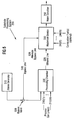
    6. The process of claim 1, wherein operation of the substrate processing chamber requires ozone for a substrate processing operation, wherein said ozone is generated by an ozone generator communicatively coupled to the substrate processing chamber, wherein said step of introducing ozone into said substrate processing chamber includes routing excess ozone from said generator into said combustion to bypass the substrate processing chamber and wherein the excess ozone is preferably abated in said combustion chamber.
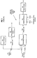
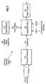
    7. A substrate processing system having an effluent gas abatement system for abating a first compound in effluent gases generated during the operation of the substrate processing system, said substrate processing system comprising:
      a substrate processing chamber having an outlet from which effluent gases are exhausted;
      an abatement unit coupled to said outlet of said substrate processing chamber for abating said effluent gases; and
      an ozone source, coupled to an inlet of said abatement unit, for providing ozone to said abatement unit to improve abatement of said effluent gases.
    8. The apparatus of claim 7, wherein said outlet of said ozone source is configurable, thereby enabling said ozone source to provide ozone to said substrate processing system and to said abatement unit.
    9. An abatement device for abating an effluent gas exhausted from a substrate processing system, comprising:
      a combustion chamber having a first inlet for receiving the effluent gas, a second inlet for receiving ozone, and an outlet for exhausting a resultant gas;
      a source of ozone coupled to said second inlet; and
      an energy source coupled to said combustion chamber for supplying energy to the effluent gas and said ozone.
    10. The apparatus of claim 9, wherein said first inlet and second inlet are the same.
    11. The apparatus of claim 7 or 9, wherein said abatement unit comprises: an ignition device for promoting a reaction between said ozone and said first compound.
    12. The apparatus of claim 7 or 9, wherein said ignition device is a thermal energy source or an electrical discharge apparatus or a radio frequency energy source which creates a plasma from the effluent gas and said ozone.
    EP98101650A 1997-02-24 1998-01-30 Process and apparatus for abating effluent gases Expired - Lifetime EP0861683B1 (en)

    Applications Claiming Priority (2)

    Application Number Priority Date Filing Date Title
    US08/805,989 US6277347B1 (en) 1997-02-24 1997-02-24 Use of ozone in process effluent abatement
    US805989 1997-02-24

    Publications (3)

    Publication Number Publication Date
    EP0861683A2 true EP0861683A2 (en) 1998-09-02
    EP0861683A3 EP0861683A3 (en) 2000-11-15
    EP0861683B1 EP0861683B1 (en) 2003-12-10

    Family

    ID=25193043

    Family Applications (1)

    Application Number Title Priority Date Filing Date
    EP98101650A Expired - Lifetime EP0861683B1 (en) 1997-02-24 1998-01-30 Process and apparatus for abating effluent gases

    Country Status (3)

    Country Link
    US (1) US6277347B1 (en)
    EP (1) EP0861683B1 (en)
    DE (1) DE69820312T2 (en)

    Cited By (9)

    * Cited by examiner, † Cited by third party
    Publication number Priority date Publication date Assignee Title
    EP1108468A1 (en) * 1999-12-17 2001-06-20 IPS Ltd Thin film deposition apparatus
    US6322756B1 (en) 1996-12-31 2001-11-27 Advanced Technology And Materials, Inc. Effluent gas stream treatment system having utility for oxidation treatment of semiconductor manufacturing effluent gases
    FR2864795A1 (en) * 2004-01-06 2005-07-08 Air Liquide Process and equipment for treating a gas containing impurities in which the gas is submitted at atmospheric pressure to a radiofrequency inductive plasma discharge
    US7141382B1 (en) 2004-10-12 2006-11-28 Parikh Chirag R Methods for detection of IL-18 as an early marker for diagnosis of acute renal failure and predictor of mortality
    US7214349B2 (en) 1996-12-31 2007-05-08 Applied Materials, Inc. Effluent gas stream treatment system having utility for oxidation treatment of semiconductor manufacturing effluent gases
    DE102007016026A1 (en) * 2007-03-30 2008-10-02 Sig Technology Ag Vacuum coating apparatus, especially CVD apparatus, has HF or microwave source, especially magnetron, mounted between coating chamber and vacuum pump to treat residual gases
    US7700049B2 (en) 2005-10-31 2010-04-20 Applied Materials, Inc. Methods and apparatus for sensing characteristics of the contents of a process abatement reactor
    US7736599B2 (en) 2004-11-12 2010-06-15 Applied Materials, Inc. Reactor design to reduce particle deposition during process abatement
    CN106659971A (en) * 2012-10-15 2017-05-10 凯能技术公司 Method and apparatus for removing contaminants from exhaust gases

    Families Citing this family (18)

    * Cited by examiner, † Cited by third party
    Publication number Priority date Publication date Assignee Title
    US6649132B1 (en) * 2002-07-23 2003-11-18 The Boc Group, Inc. Process for the removal of impurities from gas streams
    TWI230094B (en) * 2003-01-14 2005-04-01 Desiccant Technology Corp Method for exhaust treatment of perfluoro compounds
    US20060147771A1 (en) * 2005-01-04 2006-07-06 Ion America Corporation Fuel cell system with independent reformer temperature control
    US7462339B2 (en) * 2005-12-29 2008-12-09 Basf Catalysts Llc Metallic foam trap for poisons: aircraft ozone
    WO2007109081A2 (en) 2006-03-16 2007-09-27 Applied Materials, Inc. Method and apparatus for improved operation of an abatement system
    US20080081130A1 (en) * 2006-09-29 2008-04-03 Applied Materials, Inc. Treatment of effluent in the deposition of carbon-doped silicon
    KR101468606B1 (en) * 2007-05-25 2014-12-04 어플라이드 머티어리얼스, 인코포레이티드 Methods and apparatus for assembling and operating electronic device manufacturing systems
    WO2008147523A1 (en) * 2007-05-25 2008-12-04 Applied Materials, Inc. Cogeneration abatement system for electronic device manufacturing
    US20090018688A1 (en) * 2007-06-15 2009-01-15 Applied Materials, Inc. Methods and systems for designing and validating operation of abatement systems
    WO2009055750A1 (en) * 2007-10-26 2009-04-30 Applied Materials, Inc. Methods and apparatus for smart abatement using an improved fuel circuit
    US9997325B2 (en) 2008-07-17 2018-06-12 Verity Instruments, Inc. Electron beam exciter for use in chemical analysis in processing systems
    WO2011162297A1 (en) * 2010-06-25 2011-12-29 株式会社アルバック Film-forming apparatus, and method for maintaining film-forming apparatus
    US9440188B2 (en) 2012-10-15 2016-09-13 Linde Aktiengesellschaft Method for removing contaminants from exhaust gases
    EP3012011A1 (en) 2014-10-21 2016-04-27 Linde Aktiengesellschaft Method and apparatus for partial removal of contaminants from process gas stream
    GB2533933A (en) * 2015-01-06 2016-07-13 Edwards Ltd Improvements in or relating to vacuum pumping arrangements
    JP6552206B2 (en) * 2015-02-02 2019-07-31 東京エレクトロン株式会社 Exhaust pipe harmonization method and film forming apparatus
    US10269600B2 (en) 2016-03-15 2019-04-23 Applied Materials, Inc. Methods and assemblies for gas flow ratio control
    US10453721B2 (en) 2016-03-15 2019-10-22 Applied Materials, Inc. Methods and assemblies for gas flow ratio control

    Citations (5)

    * Cited by examiner, † Cited by third party
    Publication number Priority date Publication date Assignee Title
    US4941957A (en) * 1986-10-22 1990-07-17 Ultrox International Decomposition of volatile ogranic halogenated compounds contained in gases and aqueous solutions
    EP0447993A1 (en) * 1990-03-20 1991-09-25 Ebara Corporation Method and apparatus for discharging hydrogen from a vacuum vessel
    JPH05335256A (en) * 1992-06-03 1993-12-17 Fujitsu Ltd Semiconductor manufacturing device and its cleaning method
    US5569810A (en) * 1994-03-18 1996-10-29 Samco International, Inc. Method of and system for processing halogenated hydrocarbons
    EP0839929A1 (en) * 1996-10-30 1998-05-06 Applied Materials, Inc. Method and apparatus for minimizing deposition in an exhaust line

    Family Cites Families (14)

    * Cited by examiner, † Cited by third party
    Publication number Priority date Publication date Assignee Title
    JPS5111068A (en) * 1974-07-19 1976-01-28 Morio Watanabe HANDOTAI HAIGASUS HORIHO
    US4872947A (en) * 1986-12-19 1989-10-10 Applied Materials, Inc. CVD of silicon oxide using TEOS decomposition and in-situ planarization process
    US4793931A (en) 1987-09-10 1988-12-27 Solarchem Research, A Division Of Brolor Investments Limited Process for treatment of organic contaminants in solid or liquid phase wastes
    JPH0321325A (en) * 1989-06-16 1991-01-30 Mitsubishi Heavy Ind Ltd Treatment of chlorofluorocarbon vapor
    JPH0759970B2 (en) * 1989-07-19 1995-06-28 工業技術院長 CFC decomposition method
    US5451378A (en) * 1991-02-21 1995-09-19 The United States Of America As Represented By The Secretary Of The Navy Photon controlled decomposition of nonhydrolyzable ambients
    US5468356A (en) * 1991-08-23 1995-11-21 The United States Of America As Represented By The Secretary Of The Navy Large scale purification of contaminated air
    DE4202158C1 (en) * 1992-01-27 1993-07-22 Siemens Ag, 8000 Muenchen, De
    US5417826A (en) * 1992-06-15 1995-05-23 Micron Technology, Inc. Removal of carbon-based polymer residues with ozone, useful in the cleaning of plasma reactors
    US5430228A (en) 1993-02-24 1995-07-04 Hughes Aircraft Company Ozone methods for the destruction of chemical weapons
    JP3051611B2 (en) 1993-08-20 2000-06-12 日本表面化学株式会社 Cleaning solution and cleaning method for alkaline developing device
    US5453125A (en) 1994-02-17 1995-09-26 Krogh; Ole D. ECR plasma source for gas abatement
    US5663476A (en) * 1994-04-29 1997-09-02 Motorola, Inc. Apparatus and method for decomposition of chemical compounds by increasing residence time of a chemical compound in a reaction chamber
    JP3021325B2 (en) 1995-07-26 2000-03-15 日本碍子株式会社 Preventing exhaust gas duct blockage

    Patent Citations (5)

    * Cited by examiner, † Cited by third party
    Publication number Priority date Publication date Assignee Title
    US4941957A (en) * 1986-10-22 1990-07-17 Ultrox International Decomposition of volatile ogranic halogenated compounds contained in gases and aqueous solutions
    EP0447993A1 (en) * 1990-03-20 1991-09-25 Ebara Corporation Method and apparatus for discharging hydrogen from a vacuum vessel
    JPH05335256A (en) * 1992-06-03 1993-12-17 Fujitsu Ltd Semiconductor manufacturing device and its cleaning method
    US5569810A (en) * 1994-03-18 1996-10-29 Samco International, Inc. Method of and system for processing halogenated hydrocarbons
    EP0839929A1 (en) * 1996-10-30 1998-05-06 Applied Materials, Inc. Method and apparatus for minimizing deposition in an exhaust line

    Non-Patent Citations (1)

    * Cited by examiner, † Cited by third party
    Title
    PATENT ABSTRACTS OF JAPAN vol. 018, no. 158 (E-1525), 16 March 1994 (1994-03-16) & JP 05 335256 A (FUJITSU LTD), 17 December 1993 (1993-12-17) *

    Cited By (20)

    * Cited by examiner, † Cited by third party
    Publication number Priority date Publication date Assignee Title
    US6322756B1 (en) 1996-12-31 2001-11-27 Advanced Technology And Materials, Inc. Effluent gas stream treatment system having utility for oxidation treatment of semiconductor manufacturing effluent gases
    US7695700B2 (en) 1996-12-31 2010-04-13 Applied Materials, Inc. Effluent gas stream treatment system having utility for oxidation treatment of semiconductor manufacturing effluent gases
    US7214349B2 (en) 1996-12-31 2007-05-08 Applied Materials, Inc. Effluent gas stream treatment system having utility for oxidation treatment of semiconductor manufacturing effluent gases
    KR100847916B1 (en) 1999-05-07 2008-07-22 어플라이드 머티어리얼스, 인코포레이티드 Effluent gas stream treatment device and mehod having utility for oxidation treatment of semiconductor manufacturing effluent gases
    EP1198283A1 (en) * 1999-05-07 2002-04-24 Advanced Technology Materials, Inc. Effluent gas stream treatment system having utility for oxidation treatment of semiconductor manufacturing effluent gases
    EP1198283A4 (en) * 1999-05-07 2006-06-07 Advanced Tech Materials Effluent gas stream treatment system having utility for oxidation treatment of semiconductor manufacturing effluent gases
    KR100847915B1 (en) * 1999-05-07 2008-07-22 어플라이드 머티어리얼스, 인코포레이티드 Effluent gas stream treatment device and method having utility for oxidation treatment of semiconductor manufacturing effluent gases
    SG98002A1 (en) * 1999-12-17 2003-08-20 Ips Ltd Thin film deposition apparatus for semiconductor
    US6740166B2 (en) 1999-12-17 2004-05-25 Ips, Ltd. Thin film deposition apparatus for semiconductor
    EP1108468A1 (en) * 1999-12-17 2001-06-20 IPS Ltd Thin film deposition apparatus
    FR2864795A1 (en) * 2004-01-06 2005-07-08 Air Liquide Process and equipment for treating a gas containing impurities in which the gas is submitted at atmospheric pressure to a radiofrequency inductive plasma discharge
    WO2005075058A1 (en) * 2004-01-06 2005-08-18 L'air Liquide, Societe Anonyme A Directoire Et Conseil De Surveillance Pour L'etude Et L'exploitation Des Procedes Georges Claude Method for the treatment of gases using high-frequency discharges
    US7141382B1 (en) 2004-10-12 2006-11-28 Parikh Chirag R Methods for detection of IL-18 as an early marker for diagnosis of acute renal failure and predictor of mortality
    US7736599B2 (en) 2004-11-12 2010-06-15 Applied Materials, Inc. Reactor design to reduce particle deposition during process abatement
    US7985379B2 (en) 2004-11-12 2011-07-26 Applied Materials, Inc. Reactor design to reduce particle deposition during process abatement
    US7700049B2 (en) 2005-10-31 2010-04-20 Applied Materials, Inc. Methods and apparatus for sensing characteristics of the contents of a process abatement reactor
    US7736600B2 (en) 2005-10-31 2010-06-15 Applied Materials, Inc. Apparatus for manufacturing a process abatement reactor
    DE102007016026A1 (en) * 2007-03-30 2008-10-02 Sig Technology Ag Vacuum coating apparatus, especially CVD apparatus, has HF or microwave source, especially magnetron, mounted between coating chamber and vacuum pump to treat residual gases
    CN106659971A (en) * 2012-10-15 2017-05-10 凯能技术公司 Method and apparatus for removing contaminants from exhaust gases
    CN106659971B (en) * 2012-10-15 2020-10-20 凯能技术公司 Method and apparatus for removing pollutants from exhaust gas

    Also Published As

    Publication number Publication date
    DE69820312D1 (en) 2004-01-22
    EP0861683B1 (en) 2003-12-10
    US6277347B1 (en) 2001-08-21
    DE69820312T2 (en) 2004-11-18
    EP0861683A3 (en) 2000-11-15

    Similar Documents

    Publication Publication Date Title
    US6277347B1 (en) Use of ozone in process effluent abatement
    KR102470304B1 (en) Selective deposition of silicon oxide
    US7037376B2 (en) Backflush chamber clean
    EP1883769B1 (en) Gas combustion apparatus
    US6387207B1 (en) Integration of remote plasma generator with semiconductor processing chamber
    EP1304731B1 (en) Method of cleaning cvd device and cleaning device therefor
    US6468490B1 (en) Abatement of fluorine gas from effluent
    EP1028175B1 (en) Accelerated plasma cleaning
    EP0839929B1 (en) Method and apparatus for minimizing deposition in an exhaust line
    CN100468611C (en) Method and apparatus for cleaning of native oxide with hydrogen-containing radicals
    US20110034039A1 (en) Formation of silicon oxide using non-carbon flowable cvd processes
    US20090165953A1 (en) Plasma Reactor
    EP1981618B1 (en) Method of treating a gas stream
    WO2003101635A1 (en) Semiconductor device fabrication chamber cleaning method and apparatus with recirculation of cleaning gas
    KR20140009170A (en) Amine curing silicon-nitride-hydride films
    CN101229476A (en) Treatment of effluent containing chlorine-containing gas
    KR100830246B1 (en) Methods and apparatus for increasing the utilization efficiency of gases during semiconductor processing
    US20080081130A1 (en) Treatment of effluent in the deposition of carbon-doped silicon
    US20080047578A1 (en) Method for preventing clogging of reaction chamber exhaust lines
    KR20080066927A (en) Apparatus for treating a gas stream
    JPH073464A (en) Waste gas treating device
    JP2000323466A (en) Substrate processing device
    JP3827869B2 (en) Semiconductor manufacturing apparatus and cleaning method thereof
    JPH05243214A (en) Equipment for forming silicon oxide film on semiconductor substrate

    Legal Events

    Date Code Title Description
    PUAI Public reference made under article 153(3) epc to a published international application that has entered the european phase

    Free format text: ORIGINAL CODE: 0009012

    AK Designated contracting states

    Kind code of ref document: A2

    Designated state(s): DE FR GB IT NL

    AX Request for extension of the european patent

    Free format text: AL;LT;LV;MK;RO;SI

    PUAL Search report despatched

    Free format text: ORIGINAL CODE: 0009013

    AK Designated contracting states

    Kind code of ref document: A3

    Designated state(s): AT BE CH DE DK ES FI FR GB GR IE IT LI LU MC NL PT SE

    AX Request for extension of the european patent

    Free format text: AL;LT;LV;MK;RO;SI

    17P Request for examination filed

    Effective date: 20010515

    AKX Designation fees paid

    Free format text: DE FR GB IT NL

    17Q First examination report despatched

    Effective date: 20021115

    GRAH Despatch of communication of intention to grant a patent

    Free format text: ORIGINAL CODE: EPIDOS IGRA

    GRAS Grant fee paid

    Free format text: ORIGINAL CODE: EPIDOSNIGR3

    GRAA (expected) grant

    Free format text: ORIGINAL CODE: 0009210

    AK Designated contracting states

    Kind code of ref document: B1

    Designated state(s): DE FR GB IT NL

    REG Reference to a national code

    Ref country code: GB

    Ref legal event code: FG4D

    REF Corresponds to:

    Ref document number: 69820312

    Country of ref document: DE

    Date of ref document: 20040122

    Kind code of ref document: P

    ET Fr: translation filed
    PLBE No opposition filed within time limit

    Free format text: ORIGINAL CODE: 0009261

    STAA Information on the status of an ep patent application or granted ep patent

    Free format text: STATUS: NO OPPOSITION FILED WITHIN TIME LIMIT

    26N No opposition filed

    Effective date: 20040913

    PGFP Annual fee paid to national office [announced via postgrant information from national office to epo]

    Ref country code: IT

    Payment date: 20070525

    Year of fee payment: 10

    PGFP Annual fee paid to national office [announced via postgrant information from national office to epo]

    Ref country code: NL

    Payment date: 20090113

    Year of fee payment: 12

    Ref country code: DE

    Payment date: 20090130

    Year of fee payment: 12

    PGFP Annual fee paid to national office [announced via postgrant information from national office to epo]

    Ref country code: GB

    Payment date: 20081211

    Year of fee payment: 12

    PG25 Lapsed in a contracting state [announced via postgrant information from national office to epo]

    Ref country code: IT

    Free format text: LAPSE BECAUSE OF NON-PAYMENT OF DUE FEES

    Effective date: 20080130

    PGFP Annual fee paid to national office [announced via postgrant information from national office to epo]

    Ref country code: FR

    Payment date: 20090106

    Year of fee payment: 12

    REG Reference to a national code

    Ref country code: NL

    Ref legal event code: V1

    Effective date: 20100801

    GBPC Gb: european patent ceased through non-payment of renewal fee

    Effective date: 20100130

    REG Reference to a national code

    Ref country code: FR

    Ref legal event code: ST

    Effective date: 20100930

    PG25 Lapsed in a contracting state [announced via postgrant information from national office to epo]

    Ref country code: NL

    Free format text: LAPSE BECAUSE OF NON-PAYMENT OF DUE FEES

    Effective date: 20100801

    Ref country code: FR

    Free format text: LAPSE BECAUSE OF NON-PAYMENT OF DUE FEES

    Effective date: 20100201

    PG25 Lapsed in a contracting state [announced via postgrant information from national office to epo]

    Ref country code: DE

    Free format text: LAPSE BECAUSE OF NON-PAYMENT OF DUE FEES

    Effective date: 20100803

    PG25 Lapsed in a contracting state [announced via postgrant information from national office to epo]

    Ref country code: GB

    Free format text: LAPSE BECAUSE OF NON-PAYMENT OF DUE FEES

    Effective date: 20100130