EP0862080A2 - Image recording and reproducing apparatus - Google Patents
Image recording and reproducing apparatus Download PDFInfo
- Publication number
- EP0862080A2 EP0862080A2 EP98103382A EP98103382A EP0862080A2 EP 0862080 A2 EP0862080 A2 EP 0862080A2 EP 98103382 A EP98103382 A EP 98103382A EP 98103382 A EP98103382 A EP 98103382A EP 0862080 A2 EP0862080 A2 EP 0862080A2
- Authority
- EP
- European Patent Office
- Prior art keywords
- image
- display
- lcd
- switch
- output terminal
- Prior art date
- Legal status (The legal status is an assumption and is not a legal conclusion. Google has not performed a legal analysis and makes no representation as to the accuracy of the status listed.)
- Granted
Links
Images

Classifications
-
- H—ELECTRICITY
- H04—ELECTRIC COMMUNICATION TECHNIQUE
- H04N—PICTORIAL COMMUNICATION, e.g. TELEVISION
- H04N5/00—Details of television systems
- H04N5/76—Television signal recording
- H04N5/765—Interface circuits between an apparatus for recording and another apparatus
-
- H—ELECTRICITY
- H04—ELECTRIC COMMUNICATION TECHNIQUE
- H04N—PICTORIAL COMMUNICATION, e.g. TELEVISION
- H04N23/00—Cameras or camera modules comprising electronic image sensors; Control thereof
- H04N23/60—Control of cameras or camera modules
- H04N23/63—Control of cameras or camera modules by using electronic viewfinders
-
- H—ELECTRICITY
- H04—ELECTRIC COMMUNICATION TECHNIQUE
- H04N—PICTORIAL COMMUNICATION, e.g. TELEVISION
- H04N23/00—Cameras or camera modules comprising electronic image sensors; Control thereof
- H04N23/60—Control of cameras or camera modules
- H04N23/65—Control of camera operation in relation to power supply
- H04N23/651—Control of camera operation in relation to power supply for reducing power consumption by affecting camera operations, e.g. sleep mode, hibernation mode or power off of selective parts of the camera
-
- H—ELECTRICITY
- H04—ELECTRIC COMMUNICATION TECHNIQUE
- H04N—PICTORIAL COMMUNICATION, e.g. TELEVISION
- H04N5/00—Details of television systems
- H04N5/76—Television signal recording
- H04N5/765—Interface circuits between an apparatus for recording and another apparatus
- H04N5/77—Interface circuits between an apparatus for recording and another apparatus between a recording apparatus and a television camera
- H04N5/772—Interface circuits between an apparatus for recording and another apparatus between a recording apparatus and a television camera the recording apparatus and the television camera being placed in the same enclosure
-
- G—PHYSICS
- G03—PHOTOGRAPHY; CINEMATOGRAPHY; ANALOGOUS TECHNIQUES USING WAVES OTHER THAN OPTICAL WAVES; ELECTROGRAPHY; HOLOGRAPHY
- G03B—APPARATUS OR ARRANGEMENTS FOR TAKING PHOTOGRAPHS OR FOR PROJECTING OR VIEWING THEM; APPARATUS OR ARRANGEMENTS EMPLOYING ANALOGOUS TECHNIQUES USING WAVES OTHER THAN OPTICAL WAVES; ACCESSORIES THEREFOR
- G03B13/00—Viewfinders; Focusing aids for cameras; Means for focusing for cameras; Autofocus systems for cameras
- G03B13/02—Viewfinders
-
- G—PHYSICS
- G03—PHOTOGRAPHY; CINEMATOGRAPHY; ANALOGOUS TECHNIQUES USING WAVES OTHER THAN OPTICAL WAVES; ELECTROGRAPHY; HOLOGRAPHY
- G03B—APPARATUS OR ARRANGEMENTS FOR TAKING PHOTOGRAPHS OR FOR PROJECTING OR VIEWING THEM; APPARATUS OR ARRANGEMENTS EMPLOYING ANALOGOUS TECHNIQUES USING WAVES OTHER THAN OPTICAL WAVES; ACCESSORIES THEREFOR
- G03B2217/00—Details of cameras or camera bodies; Accessories therefor
- G03B2217/007—Details of energy supply or management
Abstract
Description
Claims (3)
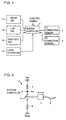
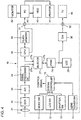
- An image recording and reproducing apparatus having an image pickup mode for picking up and recording an image, and a reproduction mode for reproducing the recorded image, comprising:an image display apparatus (29) for displaying an image to be picked up or a reproduced image;switch means (12) for setting said image display apparatus (29) to a display enabled state or a display disabled state;a digital signal output terminal (31) for applying a digital image signal to an external processing unit (41); andcontrol means (1∼3) responsive to connection of said digital signal output terminal (31) to said processing unit (41) for setting said image display apparatus (29) to the display disabled state, no matter whether said image display apparatus (29) is set to the display enabled state or the display disabled state by said switch means (12).
- The image recording and reproducing apparatus according to claim 1, wherein said digital signal output terminal is provided for applying a digital image signal to said processing unit to display said image on a monitor apparatus connected to said processing unit.
- The image recording and reproducing apparatus according to claim 1, further comprisingan analog signal output terminal (32) for applying an analog image signal to an external television receiver (45) for displaying said image on said television receiver (45); whereinsaid control means (1∼3) further sets said image display apparatus (29) to the display enabled state when said digital signal output terminal (31) is not connected to said processing unit (41) and said analog signal output terminal (32) is not connected to said television receiver (45) either, in said reproduction mode, no matter whether said image display apparatus (29) is set to the display enabled state or the display disabled state by said switch means (12).
Applications Claiming Priority (3)
| Application Number | Priority Date | Filing Date | Title |
|---|---|---|---|
| JP04366397A JP3268995B2 (en) | 1997-02-27 | 1997-02-27 | Digital camera |
| JP4366397 | 1997-02-27 | ||
| JP43663/97 | 1997-02-27 |
Publications (3)
| Publication Number | Publication Date |
|---|---|
| EP0862080A2 true EP0862080A2 (en) | 1998-09-02 |
| EP0862080A3 EP0862080A3 (en) | 2004-04-28 |
| EP0862080B1 EP0862080B1 (en) | 2007-12-05 |
Family
ID=12670102
Family Applications (1)
| Application Number | Title | Priority Date | Filing Date |
|---|---|---|---|
| EP98103382A Expired - Lifetime EP0862080B1 (en) | 1997-02-27 | 1998-02-26 | Image recording and reproducing apparatus |
Country Status (4)
| Country | Link |
|---|---|
| US (1) | US6844899B2 (en) |
| EP (1) | EP0862080B1 (en) |
| JP (1) | JP3268995B2 (en) |
| DE (1) | DE69838803T2 (en) |
Families Citing this family (16)
| Publication number | Priority date | Publication date | Assignee | Title |
|---|---|---|---|---|
| US20030063208A1 (en) * | 1996-06-12 | 2003-04-03 | Nikon Corporation | Image pick-up apparatus |
| TW448687B (en) * | 1998-03-09 | 2001-08-01 | Canon Kk | Image sensing apparatus having a protection cover |
| JP2000134527A (en) * | 1998-10-26 | 2000-05-12 | Minolta Co Ltd | Digital camera |
| JP2001036773A (en) * | 1999-07-21 | 2001-02-09 | Canon Inc | Electronic equipment, its controlling method and memory medium |
| JP2001285704A (en) * | 2000-03-31 | 2001-10-12 | Canon Inc | Image pickup device, image pickup method and storage medium |
| JP4258098B2 (en) * | 2000-05-31 | 2009-04-30 | 富士フイルム株式会社 | Electronic camera |
| US6570621B2 (en) * | 2001-05-21 | 2003-05-27 | Hewlett-Packard Development Company, L.P. | Lens cap detection |
| US6867807B2 (en) * | 2001-09-04 | 2005-03-15 | Eastman Kodak Company | Camera having single-button timed display of most-recently viewed image and default display of last verification image and method |
| JP2003338980A (en) * | 2002-05-20 | 2003-11-28 | Konica Minolta Holdings Inc | Photographing apparatus |
| JP4064877B2 (en) * | 2003-06-30 | 2008-03-19 | 株式会社東芝 | Digital camera with multiple display screens |
| JP2005277591A (en) * | 2004-03-23 | 2005-10-06 | Toshiba Corp | Electronic camera apparatus and imaging signal generating method |
| KR100586981B1 (en) * | 2004-05-12 | 2006-06-08 | 삼성전자주식회사 | Computer system and method of controlling the same |
| JP2006318585A (en) * | 2005-05-13 | 2006-11-24 | Sony Corp | Electronic apparatus, data processing method and program |
| TW200822700A (en) * | 2006-11-03 | 2008-05-16 | Innolux Display Corp | Display system and display method thereof |
| JP5683790B2 (en) * | 2009-03-03 | 2015-03-11 | 日立マクセル株式会社 | Television receiver |
| US20100283868A1 (en) * | 2010-03-27 | 2010-11-11 | Lloyd Douglas Clark | Apparatus and Method for Application of Selective Digital Photomontage to Motion Pictures |
Citations (5)
| Publication number | Priority date | Publication date | Assignee | Title |
|---|---|---|---|---|
| JPH05176294A (en) * | 1991-12-25 | 1993-07-13 | Ricoh Co Ltd | Digital electronic still camera and picture reproduction method |
| US5231501A (en) * | 1989-05-25 | 1993-07-27 | Asahi Kogaku Kogyo Kabushiki Kaisha | Still video apparatus |
| JPH06303478A (en) * | 1993-04-09 | 1994-10-28 | Sony Corp | Image pickup device |
| US5424772A (en) * | 1988-10-04 | 1995-06-13 | Asahi Kogaku Kogyo Kabushiki Kaisha | Mode changing device for still video camera and still video camera used therewith |
| JPH07298109A (en) * | 1994-04-27 | 1995-11-10 | Sony Corp | Camcorder |
Family Cites Families (15)
| Publication number | Priority date | Publication date | Assignee | Title |
|---|---|---|---|---|
| US5070406A (en) * | 1983-12-24 | 1991-12-03 | Canon Kabushiki Kaisha | Image sensing apparatus having a low-resolution monitor, means for reducing the amount of information in an image signal, and switching means for reducing power consumption in various operating modes |
| JPS6430969A (en) | 1987-07-27 | 1989-02-01 | Yamaha Motor Co Ltd | Sprocket |
| JPH01126659U (en) * | 1988-02-10 | 1989-08-30 | ||
| JPH03166880A (en) | 1989-11-27 | 1991-07-18 | Seiko Epson Corp | Electronic still camera |
| JPH0458679A (en) * | 1990-06-28 | 1992-02-25 | Canon Inc | Magnetic recording and reproducing device |
| US5479206A (en) * | 1992-02-04 | 1995-12-26 | Fuji Photo Film Co., Ltd. | Imaging system, electronic camera, computer system for controlling said electronic camera, and methods of controlling same |
| JPH06153043A (en) * | 1992-10-29 | 1994-05-31 | Sanyo Electric Co Ltd | Camera incorported type vtr |
| JPH06181527A (en) * | 1992-12-14 | 1994-06-28 | Hitachi Ltd | Vtr incorporated type camera |
| JP3548191B2 (en) * | 1993-03-22 | 2004-07-28 | キヤノン株式会社 | camera |
| JPH0746526A (en) | 1993-07-29 | 1995-02-14 | Konica Corp | Digital still camera |
| JP3542653B2 (en) * | 1995-02-14 | 2004-07-14 | 富士写真フイルム株式会社 | Image data transmission system for electronic still camera |
| US6111604A (en) * | 1995-02-21 | 2000-08-29 | Ricoh Company, Ltd. | Digital camera which detects a connection to an external device |
| US5917545A (en) * | 1995-08-31 | 1999-06-29 | Nikon Corporation | Electronic still camera that can be directly inserted in an external device |
| US5633678A (en) * | 1995-12-20 | 1997-05-27 | Eastman Kodak Company | Electronic still camera for capturing and categorizing images |
| JPH09270944A (en) | 1996-04-02 | 1997-10-14 | Canon Inc | Electronic still camera |
-
1997
- 1997-02-27 JP JP04366397A patent/JP3268995B2/en not_active Expired - Fee Related
-
1998
- 1998-02-25 US US09/030,360 patent/US6844899B2/en not_active Expired - Fee Related
- 1998-02-26 DE DE69838803T patent/DE69838803T2/en not_active Expired - Lifetime
- 1998-02-26 EP EP98103382A patent/EP0862080B1/en not_active Expired - Lifetime
Patent Citations (5)
| Publication number | Priority date | Publication date | Assignee | Title |
|---|---|---|---|---|
| US5424772A (en) * | 1988-10-04 | 1995-06-13 | Asahi Kogaku Kogyo Kabushiki Kaisha | Mode changing device for still video camera and still video camera used therewith |
| US5231501A (en) * | 1989-05-25 | 1993-07-27 | Asahi Kogaku Kogyo Kabushiki Kaisha | Still video apparatus |
| JPH05176294A (en) * | 1991-12-25 | 1993-07-13 | Ricoh Co Ltd | Digital electronic still camera and picture reproduction method |
| JPH06303478A (en) * | 1993-04-09 | 1994-10-28 | Sony Corp | Image pickup device |
| JPH07298109A (en) * | 1994-04-27 | 1995-11-10 | Sony Corp | Camcorder |
Non-Patent Citations (3)
| Title |
|---|
| PATENT ABSTRACTS OF JAPAN vol. 017, no. 587 (E-1453), 26 October 1993 (1993-10-26) & JP 05 176294 A (RICOH CO LTD), 13 July 1993 (1993-07-13) * |
| PATENT ABSTRACTS OF JAPAN vol. 1995, no. 01, 28 February 1995 (1995-02-28) & JP 06 303478 A (SONY CORP), 28 October 1994 (1994-10-28) * |
| PATENT ABSTRACTS OF JAPAN vol. 1996, no. 03, 29 March 1996 (1996-03-29) & JP 07 298109 A (SONY CORP), 10 November 1995 (1995-11-10) * |
Also Published As
| Publication number | Publication date |
|---|---|
| DE69838803T2 (en) | 2008-11-20 |
| EP0862080A3 (en) | 2004-04-28 |
| EP0862080B1 (en) | 2007-12-05 |
| US20010012071A1 (en) | 2001-08-09 |
| DE69838803D1 (en) | 2008-01-17 |
| US6844899B2 (en) | 2005-01-18 |
| JP3268995B2 (en) | 2002-03-25 |
| JPH10243324A (en) | 1998-09-11 |
Similar Documents
| Publication | Publication Date | Title |
|---|---|---|
| US6844899B2 (en) | Image recording and reproducing apparatus | |
| US6327001B1 (en) | Image processing system and information processing apparatus | |
| US6774935B1 (en) | Digital camera | |
| US6738090B2 (en) | System and method for using a single intelligence circuit for a plurality of imaging rendering components | |
| US6630958B2 (en) | Method and apparatus for storing and displaying an image taken by a rotatable image pickup portion | |
| US7443425B2 (en) | Image pickup apparatus, control method therefor, control program for implementing the control method, and storage medium storing the control program | |
| US6734915B2 (en) | Cradle-installation type digital camera, control method therefor and cradle-installation type digital camera system | |
| JPH09230495A (en) | Digital camera, external memory device and system therefor | |
| US6466263B1 (en) | Electronic still camera having pointing indicator showing operation mode | |
| US6618089B1 (en) | Display apparatus and electronic camera | |
| JP2001285703A (en) | Electronic camera | |
| US5874999A (en) | Image processing apparatus with multiple data modes | |
| US6674467B1 (en) | Digital still camera with image preview using a first and second memory and method for using the same | |
| US8154645B2 (en) | Image pickup system including image pickup device and connection device for connecting to external display device | |
| US6943835B2 (en) | Image processing method and apparatus and computer-readable storage medium having an electronic zoom function | |
| US6999115B1 (en) | Image taking apparatus with an A/D converter and DSP with variable quantization bit numbers | |
| JPH11259506A (en) | Image processing device and method and record medium | |
| US6968118B1 (en) | Image processing apparatus, its control method, and storage medium | |
| JP2004193980A (en) | Image display device | |
| JP2005521342A (en) | Electronic camera with digital effect filter | |
| JP2001275034A (en) | Electronic camera | |
| JP3344959B2 (en) | Image display device and electronic camera system | |
| JP3291398B2 (en) | Camera device | |
| JP3096272B2 (en) | Still image recording device | |
| JP2000253280A (en) | Image pickup device |
Legal Events
| Date | Code | Title | Description |
|---|---|---|---|
| PUAI | Public reference made under article 153(3) epc to a published international application that has entered the european phase |
Free format text: ORIGINAL CODE: 0009012 |
|
| AK | Designated contracting states |
Kind code of ref document: A2 Designated state(s): AT BE CH DE DK ES FI FR GB GR IE IT LI LU MC NL PT SE |
|
| AX | Request for extension of the european patent |
Free format text: AL;LT;LV;MK;RO;SI |
|
| PUAL | Search report despatched |
Free format text: ORIGINAL CODE: 0009013 |
|
| AK | Designated contracting states |
Kind code of ref document: A3 Designated state(s): AT BE CH DE DK ES FI FR GB GR IE IT LI LU MC NL PT SE |
|
| AX | Request for extension of the european patent |
Extension state: AL LT LV MK RO SI |
|
| RIC1 | Information provided on ipc code assigned before grant |
Ipc: 7H 04N 1/00 B Ipc: 7H 04N 1/21 B Ipc: 7G 03B 19/02 A |
|
| 17P | Request for examination filed |
Effective date: 20040505 |
|
| AKX | Designation fees paid |
Designated state(s): DE FR GB |
|
| 17Q | First examination report despatched |
Effective date: 20050503 |
|
| GRAP | Despatch of communication of intention to grant a patent |
Free format text: ORIGINAL CODE: EPIDOSNIGR1 |
|
| GRAS | Grant fee paid |
Free format text: ORIGINAL CODE: EPIDOSNIGR3 |
|
| GRAA | (expected) grant |
Free format text: ORIGINAL CODE: 0009210 |
|
| AK | Designated contracting states |
Kind code of ref document: B1 Designated state(s): DE FR GB |
|
| REG | Reference to a national code |
Ref country code: GB Ref legal event code: FG4D |
|
| REF | Corresponds to: |
Ref document number: 69838803 Country of ref document: DE Date of ref document: 20080117 Kind code of ref document: P |
|
| EN | Fr: translation not filed | ||
| PLBE | No opposition filed within time limit |
Free format text: ORIGINAL CODE: 0009261 |
|
| STAA | Information on the status of an ep patent application or granted ep patent |
Free format text: STATUS: NO OPPOSITION FILED WITHIN TIME LIMIT |
|
| 26N | No opposition filed |
Effective date: 20080908 |
|
| PG25 | Lapsed in a contracting state [announced via postgrant information from national office to epo] |
Ref country code: FR Free format text: LAPSE BECAUSE OF FAILURE TO SUBMIT A TRANSLATION OF THE DESCRIPTION OR TO PAY THE FEE WITHIN THE PRESCRIBED TIME-LIMIT Effective date: 20081003 |
|
| PGFP | Annual fee paid to national office [announced via postgrant information from national office to epo] |
Ref country code: GB Payment date: 20130220 Year of fee payment: 16 Ref country code: DE Payment date: 20130220 Year of fee payment: 16 |
|
| REG | Reference to a national code |
Ref country code: DE Ref legal event code: R119 Ref document number: 69838803 Country of ref document: DE |
|
| GBPC | Gb: european patent ceased through non-payment of renewal fee |
Effective date: 20140226 |
|
| REG | Reference to a national code |
Ref country code: DE Ref legal event code: R119 Ref document number: 69838803 Country of ref document: DE Effective date: 20140902 |
|
| PG25 | Lapsed in a contracting state [announced via postgrant information from national office to epo] |
Ref country code: GB Free format text: LAPSE BECAUSE OF NON-PAYMENT OF DUE FEES Effective date: 20140226 Ref country code: DE Free format text: LAPSE BECAUSE OF NON-PAYMENT OF DUE FEES Effective date: 20140902 |