EP0864297B1 - Skin stapler with multi-directional release mechanism - Google Patents
Skin stapler with multi-directional release mechanism Download PDFInfo
- Publication number
- EP0864297B1 EP0864297B1 EP98301785A EP98301785A EP0864297B1 EP 0864297 B1 EP0864297 B1 EP 0864297B1 EP 98301785 A EP98301785 A EP 98301785A EP 98301785 A EP98301785 A EP 98301785A EP 0864297 B1 EP0864297 B1 EP 0864297B1
- Authority
- EP
- European Patent Office
- Prior art keywords
- staple
- spring
- kick
- stapler
- anvil
- Prior art date
- Legal status (The legal status is an assumption and is not a legal conclusion. Google has not performed a legal analysis and makes no representation as to the accuracy of the status listed.)
- Expired - Lifetime
Links
Images


Classifications
-
- A—HUMAN NECESSITIES
- A61—MEDICAL OR VETERINARY SCIENCE; HYGIENE
- A61B—DIAGNOSIS; SURGERY; IDENTIFICATION
- A61B17/00—Surgical instruments, devices or methods, e.g. tourniquets
- A61B17/068—Surgical staplers, e.g. containing multiple staples or clamps
- A61B17/0682—Surgical staplers, e.g. containing multiple staples or clamps for applying U-shaped staples or clamps, e.g. without a forming anvil
- A61B17/0684—Surgical staplers, e.g. containing multiple staples or clamps for applying U-shaped staples or clamps, e.g. without a forming anvil having a forming anvil staying above the tissue during stapling
Definitions
- the present invention relates, in general, to tissue fastening devices and, in particular, to a new and useful wound closure device, such as a skin stapler, that allows for the multi-directional release of a staple from the device upon firing.
- One known prior art skin stapler is disclosed in U.S. Patents 4,391,402 ; 4,406,392 and 4,591,086 (Campbell et al. ). Similar to many other known skin staplers, the stapler disclosed in the above-identified patents utilities an L-shaped anvil.
- the L-shaped anvil configuration comprises an elongated leg portion and a small leg portion that is orthogonal or parallel to the elongated leg portion for providing a staple forming surface thereon. Accordingly, a former or driver is used to move parallel to the elongated leg portion in order to form a staple around the small leg portion of the anvil.
- a leaf spring which is a unitary part of the staple track, is utilized for retaining the staple stack away from the staple being formed, e.g. the distal-most staple, on the small leg portion of the anvil in order to prevent the staple stack from interfering with the forming of the distal-most staple.
- All of these skin stapler products are available in the market and utilize a similar driver and anvil configuration such as disclosed above. These devices all utilize a driver that moves substantially parallel to the elongated leg portion of the anvil in order to form a staple across the surface of the small leg portion of the anvil. Furthermore, in all of these skin stapler devices, the staple is moved away from the anvil of the instrument through the use of a spring ejector which engages the staple at the far corners of the staple crown, i.e. at the juncture of the upper most portion of the staple leg and the corner of the staple crown. Accordingly, the staple is dislodged from the surface of the anvil by using the spring ejector to force the staple off of the anvil by its crown.
- EP 0 686 374 forms the basis for the preamble of claim 1 appended hereto.
- skin staplers are generally a disposable, single patient use only device which are intended to be discarded after use in surgery, it is essential that these instruments be provided at the lowest cost possible, i.e. utilize an efficient configuration with minimal parts, without sacrificing quality, safety and functionality.
- skin stapler that provides a multi-directional release mechanism or kick-off spring for releasing staples from the instrument after firing without having to dislodge the staple from the anvil at the crown of the staple or at the juncture of the uppermost portion of the staple leg and the corner of the staple crown.
- skin stapler that provides a low featured, cost effective alternative to the skin stapler products identified above.
- the present invention relates to tissue fastening devices which include staples, such as a skin stapler, for closing wounds, incisions or curing a defect in tissue such as fastening a prosthetic to the tissue.
- the present invention is a surgical stapler as defined in claim 1 which allows for the multi-directional release of staples when fired.
- the stapler includes a stapler body and a driver contained therein.
- a magazine is connected to the stapler body and includes a staple track for carrying a plurality of staples or staple stack wherein each staple includes staple legs.
- An anvil is associated with the staple track in order to provide a staple forming surface for forming a staple thereon.
- the driver advances a staple from the staple track to the anvil in order to form the staple in a configuration that includes the formation of staple legs.
- a feeder element which is spring biased against the plurality of staples is used for feeding each staple from the staple track to the anvil.
- a trigger is operatively connected to the driver and is movable from a pre-fire position to a firing position. When actuated, the trigger advances the driver against the anvil in order to form the staple.
- the feeder element advances the staple stack along the staple track upon firing of the stapler.
- a kick-off spring is positioned beneath and substantially parallel to the staple track and to the anvil.
- the kick-off spring has a deflectable tip which is deflected away from the anvil and engages the surfaces of the staple legs.
- the deflectable tip engages the inner surfaces of the staple legs when the trigger is moved from its pre-fire position to its firing position.
- the kick-off spring ejects the staple off of and away from the anvil by disengaging the staple legs with the deflectable tip. This disengagement occurs as the deflectable tip moves in an upward direction camming along the surface of the staple legs toward the staple crown.
- the ejection of the staple from the anvil by the deflectable tip is an effective way for releasing the staple from the stapler since the staple is rotated away from the anvil due to the camming action of the deflectable tip on the inner surface of the staple legs.
- the rotatable release of the staple permits the stapler to be used and advanced in a forward linear direction and eliminates the possibility of the fired staple from re-entering the stapler after firing thus avoiding any possible jam of the instrument.
- the present invention is a tissue fastening device, such as a surgical stapler 20 which is used for the closing of wounds, incisions, defects in tissue or the fastening of a prosthetic to tissue.
- a tissue fastening device such as a surgical stapler 20 which is used for the closing of wounds, incisions, defects in tissue or the fastening of a prosthetic to tissue.
- the stapler 20 is generally used as a skin stapler for the uses identified above.
- the stapler 20 comprises a stapler body 22 having an ergonomic handle 24 which is integral with the body 22.
- a trigger 26 is operatively connected to the body 22 as best illustrated in Fig. 1. Described below are a number of key features of the present invention as best illustrated in Figs. 1 through 2B. However, a more detailed description of these features and functions can be found in U.S. 4,179,057 (Becht et al. ). Although not identified by the same name or same reference numeral, the features of the stapler 20 according to the present invention are similar in function to those described in U.S. 4,179,057 and are well within the purview of one of ordinary skill in the surgical field.
- the stapler body 22 includes a pivot bar recess 23 and an actuator recess 25 adjacent each other at the distal end of the stapler body 22.
- the actuating trigger 26 includes two arms 26a and 26b which define a substantially Y-shaped configuration for the trigger 26 and is rotatably connected to the stapler body 22.
- a pivot bar 28 is fixed between the trigger arms 26a and 26b and is received in the pivot bar recess 23 of the stapler body 22.
- the trigger arms 26a and 26b also include a trunion recess 27 at the distal end of the arms 26a and 26b.
- An actuator 70 includes a driver detent 72 and trunions 74 located at opposite ends of the actuator 70.
- the trunions 74 are received in the trunion recesses 27 of the trigger arms 26a and 26b. Additionally, the trunions 74 are received in the actuator recess 25 of the stapler body 22. Accordingly, the above-mentioned arrangement, allows for the trigger 26 to be rotated in a direction R from a pre-fire position P to a firing position F, indicated by phantom lines, upon the depression of the trigger 26 as best shown in Fig. 1.
- the trigger 26 When depressed or squeezed by the surgeon, the trigger 26 will be moved or rotated in direction R toward the handle 24 since the trunions 74 of the actuator 70 are moveable in the actuator recess 25 of the stapler body 22 and the pivot bar 28 is movable in the pivot bar recess 23 of the stapler body 22.
- a driver 80 having a detent aperture 81 located at the proximal end of the driver 80 is connected to the driver detent 72 of the actuator 70.
- the driver 80 also includes driver tines 82 which are located at the distal end of the driver 80.
- the actuator 70 includes an upper spring post 76 for receiving a return spring 68.
- the return spring 68 is also in engagement with a spring seat 60 having a lower spring post 64 for receiving the spring 68 thereon. Accordingly, the return spring 68 is resilientally positioned between the upper spring post 76 of the actuator 70 and the lower spring post 64 of the spring seat 60.
- a magazine 29 including a lower magazine section 30 and an upper magazine section 32 is connected to the stapler body 22 as shown in Fig. 1.
- the upper magazine section 32 includes a feeder spring recess 35 at the distal end of the upper magazine section 32.
- the feeder spring recess 35 receives a feeder spring 54 and also supports the spring seat 60.
- the upper magazine section 32 also includes a longitudinal slot 32a for receiving a feeder shoe lug 53 of a feeder shoe 52.
- the feeder shoe lug 53 is movable in the slot 32a of the upper magazine section 32 and is movably engaged with the feeder spring 54.
- the magazine 29 also includes a staple track 36 for carrying a plurality of staples or a staple stack 49 (Fig. 3B).
- the staple track 36 includes an anvil 38 located at the distal-most portion of the staple track 36.
- the anvil 38 provides a surface for the formation of a staple 50 thereabout upon the firing of the stapler 20.
- the feeder shoe 52 is held under tension by the engagement of the feeder shoe lug 53 in engagement with the feeder spring 54.
- This spring-biased arrangement ensures that the staple stack 49 (Fig. 3B) is continuously urged distally along the staple track 36 such that the lead staple 50 is always positioned on the anvil 38.
- the magazine 29 also includes a kick-off spring 40 which is positioned beneath the staple track 36 and above the lower magazine section 30.
- the kick-off spring 40 can be made of any material, but is preferably made of a plastic material.
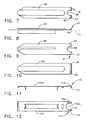
- the kick-off spring 40 has a deflectable tip generally designated 41 comprising a pair of beveled tip surfaces 42 which are upwardly inclined at an angle with respect to a longitudinal axis L 1 of the kick-off spring 40 (Fig. 8).
- a notch 48 is interposed between the beveled tip surfaces 42.
- the lower magazine section 30 also includes a front face 31 at the distal end of the lower magazine section 30 and a skin contact surface 33 at the under side of the lower magazine section 30 near its distal end.
- the front face 31 and the contact surface 33 define an opening 34 at the distal end of the lower magazine section 30.
- the anvil 38 and the deflectable tip 41 of the kick-off spring 40 are located at the opening 34 in the lower magazine section 30 for permitting the lead staple 50 to be fired and ejected from the stapler 20 (Fig. 1).
- the stapler 20 When in use, the stapler 20 is placed against tissue 100 (Fig. 6B) by placing the lower surface 33 of the lower magazine section 30 directly on the tissue 100 such that the opening 34 of the lower magazine section 30 is located at a position over the tissue 100 where the surgeon desires to place the staple 50.
- the surgeon employs a firing sequence using the stapler 20 as best illustrated in Figs. 3A through 6C.
- Fig. 3A shows the stapler 20 in its pre-fire position P (Fig. 1) wherein the lead staple 50 is positioned on the anvil 38.
- the driver tines 82 of the driver 80 are positioned above the lead staple 50 and are positioned a short distance from the lead staple 50 defining a gap therebetween.
- the beveled tip surfaces 42 are positioned flush against the anvil 38 at the under side of the anvil 38 as shown in Figs. 3A and 3B.
- the driver 80 is advanced toward the lead staple 50 and the anvil 38 such that the driver tines 82 contact the lead staple 50 and begin the staple forming process.
- the lead staple 50 begins to be formed in a configuration that includes the formation of staple legs 51.
- the beveled tip surfaces 42 of the kick-off spring 40 include an angled outer edge 43 which provide a camming surface for the inner surfaces of the staple legs 51 of the lead staple 50.
- the inner surfaces of the staple legs 51 contact the angled outer edge 43 of the beveled tips 42 thereby providing a camming surface for the staple legs 51.
- the deflectable tip 41 e.g. the beveled tip surfaces 42, are deflected away from the anvil 38 in a downward direction and downwardly cam against the inner surfaces of the staple legs 51.
- Figs. 6A-6C show the inner surfaces of the staple legs 51 of the lead staple 50 in contact with the staple legs 51 of the staple 50 near the distal end of the staple legs 51.
- the deflectable tip returns to its initial position, e.g. flush against the anvil 38, by riding or camming upwardly against the inner surfaces of the staple legs 51 causing the lead staple 50 to rotate about a rotation point 50a as best shown in Fig. 6B.
- the rotation point 50a is the point in the tissue 100 whereby the staple legs 51 are anchored in the tissue 100.
- the deflectable tip 41 returns to the anvil 38 with such force that it cams against the staple legs 51 such that the lead staple 50 is rotated at an angle ⁇ away from the axis of the driver 80 and the rotation point 50a.
- the angle of rotation a is a significant angle of rotation that serves as an anvil clearance angle such that the lead staple 50 is lifted off and away from or ejected from the anvil 38 by the return camming action of the deflectable tip 41.
- the ejection of the lead staple 50 from the stapler 20 at the anvil clearance angle ⁇ provides for a multi-directional release for the fired staple 50 that does not permit the fired staple 50 to re-enter the stapler 20 thereby avoiding any possible jamming of the instrument.
- Fig. 10 illustrates a second embodiment of a kick-off spring 90 that includes a deflectable tip 92 which is a single, uniform beveled surface and includes an angled outer edge 94 near each corner of the deflectable tip 92.
- the angled outer edges 94 are camming surfaces for the staple legs 51 and function such as described above.
- the angled outer edges 94 are located at each end of the deflectable tip 92.
- Figs. 11 and 12 illustrate a third embodiment of a kick-off spring 110 having a deflectable tip 111 which includes a pair of beveled tips 112.
- a gap 112a is interposed between the beveled tip surfaces 112.
- Each beveled tip surface 112 includes an angled outer edge 113 as a camming surface for the staple legs 51 of the lead staple 50 (Fig. 5C).
- the beveled tip surfaces 112 also include a curled outer surface 114 extending upwardly from the angled outer edge 113 defining a substantially C-shaped configuration as best shown in Fig. 11.
- the kick-off spring 90 of Fig. 10 and the kick-off spring 110 of Figs. 11 and 12 operate in a similar fashion to the operation of the kick-off spring 40 illustrated in Figs. 7-9.
- the kick-off spring 40 of Figs. 7-9 is the preferred embodiment of a kick-off spring according to the present invention, it can be appreciated by one of ordinary skill in the surgical field that the alternative kick-off springs 90 and 110 can be utilized in lieu of the preferred kick-off spring 40 and substituted therefor.
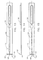
- Figs. 13-15 illustrate a fourth embodiment of a kick-off spring 120 according to the present invention which can be utilized with the stapler 20 of the present invention.
- the kick-off spring 120 includes a longitudinal slot 122 extending along a substantial portion of a longitudinal axis L 2 of the kick-off spring 120.
- the kick-off spring 120 also includes a deflectable tip generally designated 123 comprising a pair of beveled tines 124 beveled at an angle upwardly from the upper surface of the kick-off spring 120.
- the beveled tines 124 include an angled outer edge 126 which act as a camming surface for the lead staple 50 similar to that described above.
- the beveled tines also include an inner edge 128 located at the distal-most portion of the longitudinal slot 122.
- the beveled tines 124 are deflectable inwardly toward the longitudinal axis L 2 of the kick-off spring 120 such that the inner edge 128 of each beveled tine 124 crosses the longitudinal axis L 2 of the kick-off spring 120.
- the beveled tines 124 overlap each other. This inward deflection of the beveled tines 124 is caused by the staple legs 51 during the staple forming process similar to the manner described above.
- the beveled tines 124 are not only deflected slightly in a downward direction away from the anvil 38, but are also primarily deflected inwardly toward the longitudinal axis L 2 of the kick-off spring 120. This inward deflection of the beveled tines 124 permits each beveled tine 124 to cross the longitudinal axis L 2 thereby covering the distal end portion of the slot 122. This inward deflection results in a deflected configuration whereby one beveled tine 124 is partially covering the other beveled tine 124 such as shown in Fig. 15.
- the kick-off spring 120 is moved to its deflected position as a result of the trigger 26 being actuated from its pre-fire position P to its firing position F such as described above and illustrated in Fig. 1.
- the staple 50 is lifted off and away from the anvil 38 thereby ejecting the staple 50 from the anvil 38 as the beveled tines 124 are deflected back outwardly and upwardly away from the longitudinal axis L 2 of the kick-off spring 120 to resume an original position as best shown in Fig. 13.
- the staple 50 is sufficiently ejected from the stapler 20 in a manner which allows for the multi-directional release of the staple 50 thereby permitting the stapler 20 to be moved distally upon subsequent firings in a forward, distal direction from the surgeon.
Description
- The present invention relates, in general, to tissue fastening devices and, in particular, to a new and useful wound closure device, such as a skin stapler, that allows for the multi-directional release of a staple from the device upon firing.
- It is well established in the prior art that there are many devices that exist which utilize staples for fastening tissue. Many of these existing or known devices are directed toward closing a wound, fastening a skin incision, curing a defect in tissue or fastening a prosthetic to tissue for repairing a defect or the like.
- In particular, there are a number of known prior art skin staplers that contain a multiplicity of staples and are used for closing wounds or incisions in the skin. These skin staplers are usually multi-fire instruments meaning that they contain and fire a plurality of staples. These instruments are designed to be disposable and used for a single patient only.
- One known prior art skin stapler is disclosed in
U.S. Patents 4,391,402 ;4,406,392 and4,591,086 (Campbell et al. ). Similar to many other known skin staplers, the stapler disclosed in the above-identified patents utilities an L-shaped anvil. The L-shaped anvil configuration comprises an elongated leg portion and a small leg portion that is orthogonal or parallel to the elongated leg portion for providing a staple forming surface thereon. Accordingly, a former or driver is used to move parallel to the elongated leg portion in order to form a staple around the small leg portion of the anvil. In conjunction with the driver and anvil configuration and orientation, a leaf spring, which is a unitary part of the staple track, is utilized for retaining the staple stack away from the staple being formed, e.g. the distal-most staple, on the small leg portion of the anvil in order to prevent the staple stack from interfering with the forming of the distal-most staple. - Other known skin staplers are disclosed in
U.S. 3,643,851 (Green et al. ) andU.S. 4,127,227 (Green ). Similar to the prior art devices described above, these skin staplers utilize a similar anvil having a substantially L-shaped configuration. Additionally, the driver for these stapling instruments is advanced parallel to the elongated leg portion of the anvil. Additionally, a spring ejector is located adjacent the anvil for engaging the formed staple at the crown of the staple in order to lift the staple off of the anvil by its crown after firing. - In addition to the skin staplers identified above, there are other known skin staplers which also utilize a spring ejector for ensuring that the formed staple is moved away from the anvil of the instrument. These devices are identified as follows: the PRECISE PGX™, manufactured and sold by 3M Healthcare, St. Paul, Minnesota; the Davis-Geck APPOSE ULC™, manufactured and sold by American Cyanamid Company, Danbury, Connecticut; VISISTAT RH™, manufactured and sold by Edward Weck and Company, Inc., Research Triangle Park, North Carolina; and the Auto Suture (Cricket™, Royal™, Signet™, Concorde™, Elite™ and Multi-fire Premium™) skin stapler products, manufactured and sold by United States Surgical Corporation, Norwalk, Connecticut. All of these skin stapler products are available in the market and utilize a similar driver and anvil configuration such as disclosed above. These devices all utilize a driver that moves substantially parallel to the elongated leg portion of the anvil in order to form a staple across the surface of the small leg portion of the anvil. Furthermore, in all of these skin stapler devices, the staple is moved away from the anvil of the instrument through the use of a spring ejector which engages the staple at the far corners of the staple crown, i.e. at the juncture of the upper most portion of the staple leg and the corner of the staple crown. Accordingly, the staple is dislodged from the surface of the anvil by using the spring ejector to force the staple off of the anvil by its crown.
- As noted above, all of the known skin stapler devices utilize similar staple forming and staple release features, namely a spring ejector which releases the staple from the anvil at the crown of the staple. Accordingly, most of these instruments contain a similar number of parts. Thus, most of these known devices are manufactured at around a similar cost with respect to the number of parts utilized in these instruments.
- Other staplers are disclosed in
EP 0 686 374 ,EP 0 685 203 ,EP 0 324 166 ,US 4 523 707 andUS 4 179 057 .EP 0 686 374 forms the basis for the preamble of claim 1 appended hereto. - Since skin staplers are generally a disposable, single patient use only device which are intended to be discarded after use in surgery, it is essential that these instruments be provided at the lowest cost possible, i.e. utilize an efficient configuration with minimal parts, without sacrificing quality, safety and functionality. Presently, there is no known skin stapler that provides a multi-directional release mechanism or kick-off spring for releasing staples from the instrument after firing without having to dislodge the staple from the anvil at the crown of the staple or at the juncture of the uppermost portion of the staple leg and the corner of the staple crown. Additionally, there is no known skin stapler that provides a low featured, cost effective alternative to the skin stapler products identified above.
- The present invention relates to tissue fastening devices which include staples, such as a skin stapler, for closing wounds, incisions or curing a defect in tissue such as fastening a prosthetic to the tissue. The present invention is a surgical stapler as defined in claim 1 which allows for the multi-directional release of staples when fired. The stapler includes a stapler body and a driver contained therein. A magazine is connected to the stapler body and includes a staple track for carrying a plurality of staples or staple stack wherein each staple includes staple legs. An anvil is associated with the staple track in order to provide a staple forming surface for forming a staple thereon.
- When the stapler is actuated by the user, the driver advances a staple from the staple track to the anvil in order to form the staple in a configuration that includes the formation of staple legs. A feeder element which is spring biased against the plurality of staples is used for feeding each staple from the staple track to the anvil.
- A trigger is operatively connected to the driver and is movable from a pre-fire position to a firing position. When actuated, the trigger advances the driver against the anvil in order to form the staple. The feeder element advances the staple stack along the staple track upon firing of the stapler.
- A kick-off spring is positioned beneath and substantially parallel to the staple track and to the anvil. The kick-off spring has a deflectable tip which is deflected away from the anvil and engages the surfaces of the staple legs. The deflectable tip engages the inner surfaces of the staple legs when the trigger is moved from its pre-fire position to its firing position. As the trigger is released from its firing position, the kick-off spring ejects the staple off of and away from the anvil by disengaging the staple legs with the deflectable tip. This disengagement occurs as the deflectable tip moves in an upward direction camming along the surface of the staple legs toward the staple crown.
- The ejection of the staple from the anvil by the deflectable tip is an effective way for releasing the staple from the stapler since the staple is rotated away from the anvil due to the camming action of the deflectable tip on the inner surface of the staple legs. The rotatable release of the staple permits the stapler to be used and advanced in a forward linear direction and eliminates the possibility of the fired staple from re-entering the stapler after firing thus avoiding any possible jam of the instrument.
- It is an object of the present invention to provide a surgical stapler that allows for the multi-directional release of the staple upon firing.
- It is another object of the present invention to provide a surgical stapler that utilizes a kick-off spring to eject the staple from the stapler in a manner which prevents re-entering of the staple into the instrument and avoids jamming or misfiring.
- It is another object of the present invention to provide a surgical stapler that enables the surgeon to fire and advance the stapler in a forward, linear direction away from the surgeon.
- It is another object of the present invention to provide a surgical stapler with a kick-off spring that is cost effective and easy to manufacture and provides a low cost alternative to other known surgical staplers that utilize staple ejection springs.
- The various features of novelty which characterize the invention are pointed out with particularity in the claims annexed to and forming a part of this disclosure. For a better understanding of the invention, its operating advantages and specific objects attained by its uses, reference is made to the accompanying drawings and descriptive matter in which preferred embodiments of the invention are illustrated.
-
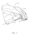
- Fig. 1 is a perspective view of a preferred embodiment of an improved surgical stapler according to the present invention;
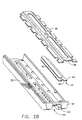
- Fig. 2A is an exploded perspective view of the surgical stapler of Fig. 1;
- Fig. 2B is an enlarged exploded perspective view of the lower portion of Fig. 1 illustrating a lower magazine, a kick-off spring, a staple track and an anvil;
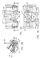
- Fig. 3A is a front view of the stapler according to the present invention having a front portion thereof removed to show the staple forming elements in working relationship with each other;
- Fig. 3B is a centerline section taken along
line 3B-3B of Fig. 3A showing the stapler according to the present invention in a pre-fire position; - Fig. 3C is a bottom view of the working end of the surgical stapler according to the present invention taken along
line 3C-3C of Fig. 3A illustrating the relationship of a leading staple to the kick-off spring; - Fig. 4A is another front view of the stapler according to the present invention illustrating the formation of a staple at a point on an inner surface of the staple legs where the staple initially contacts the kick-off spring;
- Fig. 4B is a centerline section taken along
line 4B-4B of Fig. 4A; - Fig. 4C is a bottom view taken along
line 4C-4C of Fig. 4A illustrating the staple in initial contact with the kick-off spring at the inner surface of the staple legs; - Fig. 5A is another front view of the stapler according to the present invention illustrating further closure of the staple and an intermediate flexure of the kick-off spring;
- Fig. 5B is a centerline section taken along
line 5B-5B of Fig. 5A illustrating the flexure of the kick-off spring; - Fig. 5C is a bottom view taken along
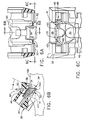
line 5C-5C of Fig. 5A illustrating the camming movement of the staple legs about the angled outer edges of the kick-off spring; - Fig. 6A is another front view of the stapler according to the present invention showing a fully formed staple;
- Fig. 6B is a centerline section taken along
line 6B-6B of Fig. 6A illustrating the full flexure of the kick-off spring; - Fig. 6C is a bottom view taken along
line 6C-6C of Fig. 6A illustrating the position of the staple legs against the beveled tip surfaces of the kick-off spring; - Fig. 7 is a plan view of a preferred embodiment of a kick-off spring according to the present invention;
- Fig. 8 is a side elevational view of the kick-off spring of Fig. 7;
- Fig. 9 is a bottom view of the kick-off spring of Fig. 7;
- Fig. 10 is a plan view of an alternate embodiment of a kick-off spring having a continuous beveled tip surface;
- Fig. 11 is a side elevational view in section of another alternate embodiment of a kick-off spring having tips with curled edges;
- Fig. 12 is a bottom view of the kick-off spring of Fig. 11;
- Fig. 13 is a plan view of another alternate embodiment of a kick-off spring having a split body;
- Fig. 14 is a side elevational view of the kick-off spring of Fig. 15; and
- Fig. 15 is a plan view of the kick-off spring of Fig. 13 in its deflected form.
- As shown in Fig. 1, the present invention is a tissue fastening device, such as a
surgical stapler 20 which is used for the closing of wounds, incisions, defects in tissue or the fastening of a prosthetic to tissue. - The
stapler 20 is generally used as a skin stapler for the uses identified above. Thestapler 20 comprises astapler body 22 having anergonomic handle 24 which is integral with thebody 22. Atrigger 26 is operatively connected to thebody 22 as best illustrated in Fig. 1. Described below are a number of key features of the present invention as best illustrated in Figs. 1 through 2B. However, a more detailed description of these features and functions can be found inU.S. 4,179,057 (Becht et al. ). Although not identified by the same name or same reference numeral, the features of thestapler 20 according to the present invention are similar in function to those described inU.S. 4,179,057 and are well within the purview of one of ordinary skill in the surgical field. - As best illustrated in Fig. 2A, the
stapler body 22 includes apivot bar recess 23 and anactuator recess 25 adjacent each other at the distal end of thestapler body 22. Theactuating trigger 26 includes twoarms trigger 26 and is rotatably connected to thestapler body 22. Apivot bar 28 is fixed between thetrigger arms pivot bar recess 23 of thestapler body 22. Thetrigger arms trunion recess 27 at the distal end of thearms - An
actuator 70 includes adriver detent 72 andtrunions 74 located at opposite ends of theactuator 70. Thetrunions 74 are received in the trunion recesses 27 of thetrigger arms trunions 74 are received in theactuator recess 25 of thestapler body 22. Accordingly, the above-mentioned arrangement, allows for thetrigger 26 to be rotated in a direction R from a pre-fire position P to a firing position F, indicated by phantom lines, upon the depression of thetrigger 26 as best shown in Fig. 1. When depressed or squeezed by the surgeon, thetrigger 26 will be moved or rotated in direction R toward thehandle 24 since thetrunions 74 of theactuator 70 are moveable in theactuator recess 25 of thestapler body 22 and thepivot bar 28 is movable in thepivot bar recess 23 of thestapler body 22. - A
driver 80 having adetent aperture 81 located at the proximal end of thedriver 80 is connected to thedriver detent 72 of theactuator 70. Thedriver 80 also includesdriver tines 82 which are located at the distal end of thedriver 80. Theactuator 70 includes anupper spring post 76 for receiving areturn spring 68. Thereturn spring 68 is also in engagement with aspring seat 60 having alower spring post 64 for receiving thespring 68 thereon. Accordingly, thereturn spring 68 is resilientally positioned between theupper spring post 76 of theactuator 70 and thelower spring post 64 of thespring seat 60. - A
magazine 29 including alower magazine section 30 and anupper magazine section 32 is connected to thestapler body 22 as shown in Fig. 1. Theupper magazine section 32 includes afeeder spring recess 35 at the distal end of theupper magazine section 32. Thefeeder spring recess 35 receives afeeder spring 54 and also supports thespring seat 60. Theupper magazine section 32 also includes alongitudinal slot 32a for receiving afeeder shoe lug 53 of afeeder shoe 52. Thefeeder shoe lug 53 is movable in theslot 32a of theupper magazine section 32 and is movably engaged with thefeeder spring 54. - The
magazine 29 also includes astaple track 36 for carrying a plurality of staples or a staple stack 49 (Fig. 3B). Thestaple track 36 includes ananvil 38 located at the distal-most portion of thestaple track 36. Theanvil 38 provides a surface for the formation of a staple 50 thereabout upon the firing of thestapler 20. - The
feeder shoe 52 is held under tension by the engagement of thefeeder shoe lug 53 in engagement with thefeeder spring 54. This spring-biased arrangement ensures that the staple stack 49 (Fig. 3B) is continuously urged distally along thestaple track 36 such that thelead staple 50 is always positioned on theanvil 38. - The
magazine 29 also includes a kick-off spring 40 which is positioned beneath thestaple track 36 and above thelower magazine section 30. The kick-off spring 40 can be made of any material, but is preferably made of a plastic material. As best shown in Fig. 2B, the kick-off spring 40 has a deflectable tip generally designated 41 comprising a pair of beveled tip surfaces 42 which are upwardly inclined at an angle with respect to a longitudinal axis L1 of the kick-off spring 40 (Fig. 8). Anotch 48 is interposed between the beveled tip surfaces 42. Although the kick-off spring 40 is shown and described as a separate component, it is well within the ability of one of ordinary skill in the surgical field to utilize a kick-off spring that is integral with either thestaple track 36 or thelower magazine section 30. - The
lower magazine section 30 also includes afront face 31 at the distal end of thelower magazine section 30 and askin contact surface 33 at the under side of thelower magazine section 30 near its distal end. Thefront face 31 and thecontact surface 33 define anopening 34 at the distal end of thelower magazine section 30. As shown in Figs. 3B and 3C, theanvil 38 and thedeflectable tip 41 of the kick-off spring 40 are located at theopening 34 in thelower magazine section 30 for permitting thelead staple 50 to be fired and ejected from the stapler 20 (Fig. 1). - When in use, the
stapler 20 is placed against tissue 100 (Fig. 6B) by placing thelower surface 33 of thelower magazine section 30 directly on thetissue 100 such that theopening 34 of thelower magazine section 30 is located at a position over thetissue 100 where the surgeon desires to place thestaple 50. Upon positioning thestapler 20, the surgeon employs a firing sequence using thestapler 20 as best illustrated in Figs. 3A through 6C. Fig. 3A shows thestapler 20 in its pre-fire position P (Fig. 1) wherein thelead staple 50 is positioned on theanvil 38. The driver tines 82 of thedriver 80 are positioned above thelead staple 50 and are positioned a short distance from thelead staple 50 defining a gap therebetween. The beveled tip surfaces 42 are positioned flush against theanvil 38 at the under side of theanvil 38 as shown in Figs. 3A and 3B. - As the
trigger 26 is depressed and rotated in direction R toward thehandle 24 of thestapler 20 in an upward direction as indicated by Fig. 1, thedriver 80 is advanced toward thelead staple 50 and theanvil 38 such that thedriver tines 82 contact thelead staple 50 and begin the staple forming process. As thedriver tines 82 are advanced in a downward direction, thelead staple 50 begins to be formed in a configuration that includes the formation ofstaple legs 51. - As best shown in Figs. 7-9, the beveled tip surfaces 42 of the kick-
off spring 40 include an angledouter edge 43 which provide a camming surface for the inner surfaces of thestaple legs 51 of thelead staple 50. - As shown in Figs. 4A through 5C, the inner surfaces of the
staple legs 51 contact the angledouter edge 43 of thebeveled tips 42 thereby providing a camming surface for thestaple legs 51. As shown in Figs. 5A through 6C, as thelead staple 50 is formed against theanvil 38 through the downward force provided bydriver tines 82, thedeflectable tip 41, e.g. the beveled tip surfaces 42, are deflected away from theanvil 38 in a downward direction and downwardly cam against the inner surfaces of thestaple legs 51. As the tip surfaces 42 of thedeflectable tip 41 are being deflected away from theanvil 38, the inner surfaces of thestaple legs 51 of thelead staple 50 cam about the angledouter edge 43 of thebeveled tips 42 until thelead staple 50 is formed in a final box-like configuration (Figs. 6A-6C) and thedeflectable tip 41 achieves a maximum deflection as illustrated in Fig. 6B. A maximum deflection of thedeflectable tip 41 is achieved at a point where thetrigger 26 is depressed to thehandle 24 at its firing position F (Fig. 1). Figs. 6A and 6B show the beveled tip surfaces 42 of thedeflectable tip 41 in contact with thestaple legs 51 of the staple 50 near the distal end of thestaple legs 51. Accordingly, as thetrigger 26 is permitted to be released from its firing position F, the deflectable tip returns to its initial position, e.g. flush against theanvil 38, by riding or camming upwardly against the inner surfaces of thestaple legs 51 causing thelead staple 50 to rotate about arotation point 50a as best shown in Fig. 6B. Therotation point 50a is the point in thetissue 100 whereby thestaple legs 51 are anchored in thetissue 100. Thedeflectable tip 41 returns to theanvil 38 with such force that it cams against thestaple legs 51 such that thelead staple 50 is rotated at an angle α away from the axis of thedriver 80 and therotation point 50a. The angle of rotation a is a significant angle of rotation that serves as an anvil clearance angle such that thelead staple 50 is lifted off and away from or ejected from theanvil 38 by the return camming action of thedeflectable tip 41. The ejection of thelead staple 50 from thestapler 20 at the anvil clearance angle α provides for a multi-directional release for the firedstaple 50 that does not permit the firedstaple 50 to re-enter thestapler 20 thereby avoiding any possible jamming of the instrument. - Fig. 10 illustrates a second embodiment of a kick-
off spring 90 that includes adeflectable tip 92 which is a single, uniform beveled surface and includes an angledouter edge 94 near each corner of thedeflectable tip 92. Likewise, the angledouter edges 94 are camming surfaces for thestaple legs 51 and function such as described above. The angledouter edges 94 are located at each end of thedeflectable tip 92. - Figs. 11 and 12 illustrate a third embodiment of a kick-
off spring 110 having adeflectable tip 111 which includes a pair ofbeveled tips 112. Agap 112a is interposed between the beveled tip surfaces 112. Eachbeveled tip surface 112 includes an angledouter edge 113 as a camming surface for thestaple legs 51 of the lead staple 50 (Fig. 5C). The beveled tip surfaces 112 also include a curledouter surface 114 extending upwardly from the angledouter edge 113 defining a substantially C-shaped configuration as best shown in Fig. 11. - The kick-
off spring 90 of Fig. 10 and the kick-off spring 110 of Figs. 11 and 12 operate in a similar fashion to the operation of the kick-off spring 40 illustrated in Figs. 7-9. Although the kick-off spring 40 of Figs. 7-9 is the preferred embodiment of a kick-off spring according to the present invention, it can be appreciated by one of ordinary skill in the surgical field that the alternative kick-off springs 90 and 110 can be utilized in lieu of the preferred kick-off spring 40 and substituted therefor. - Figs. 13-15 illustrate a fourth embodiment of a kick-
off spring 120 according to the present invention which can be utilized with thestapler 20 of the present invention. The kick-off spring 120 includes alongitudinal slot 122 extending along a substantial portion of a longitudinal axis L2 of the kick-off spring 120. The kick-off spring 120 also includes a deflectable tip generally designated 123 comprising a pair ofbeveled tines 124 beveled at an angle upwardly from the upper surface of the kick-off spring 120. Thebeveled tines 124 include an angledouter edge 126 which act as a camming surface for thelead staple 50 similar to that described above. The beveled tines also include aninner edge 128 located at the distal-most portion of thelongitudinal slot 122. - As shown in Fig. 15, the
beveled tines 124 are deflectable inwardly toward the longitudinal axis L2 of the kick-off spring 120 such that theinner edge 128 of eachbeveled tine 124 crosses the longitudinal axis L2 of the kick-off spring 120. When deflected in this manner, thebeveled tines 124 overlap each other. This inward deflection of thebeveled tines 124 is caused by thestaple legs 51 during the staple forming process similar to the manner described above. As thestaple 50 is being formed against theanvil 38, thebeveled tines 124 are not only deflected slightly in a downward direction away from theanvil 38, but are also primarily deflected inwardly toward the longitudinal axis L2 of the kick-off spring 120. This inward deflection of thebeveled tines 124 permits eachbeveled tine 124 to cross the longitudinal axis L2 thereby covering the distal end portion of theslot 122. This inward deflection results in a deflected configuration whereby onebeveled tine 124 is partially covering the otherbeveled tine 124 such as shown in Fig. 15. - The kick-
off spring 120 is moved to its deflected position as a result of thetrigger 26 being actuated from its pre-fire position P to its firing position F such as described above and illustrated in Fig. 1. Upon the release of theactuation trigger 26 from its firing position F, thestaple 50 is lifted off and away from theanvil 38 thereby ejecting the staple 50 from theanvil 38 as thebeveled tines 124 are deflected back outwardly and upwardly away from the longitudinal axis L2 of the kick-off spring 120 to resume an original position as best shown in Fig. 13. The returning of thebeveled tines 124 to their original position enables thedriver tines 82 to cam against the inner surfaces of thestaple legs 51 for achieving a staple ejection and staple rotation in a similar manner to that described above. Thus, when using the kick-off spring 120, thestaple 50 is sufficiently ejected from thestapler 20 in a manner which allows for the multi-directional release of the staple 50 thereby permitting thestapler 20 to be moved distally upon subsequent firings in a forward, distal direction from the surgeon.
Claims (10)
- A surgical- stapler (20) for applying a staple in tissue, the stapler (20) comprising:a stapler body (22) having a driver (80);a magazine (29) connected to said stapler body (22), said magazine (29) including:a staple track (36) for carrying a plurality of stapes (49) wherein each of said staples has staple legs,an anvil (38) associated with said staple track (36) and having a staple forming surface for forming each of said staples (50) thereon, anda feeder element (52) spring biased against said plurality of staples (49) for feeding each of said staples (49) from said staple track (36) to said anvil (38);and a trigger (26) operatively connected to said driver (80) for advancing said driver (80) against said anvil (38) so as to form said staple (50) against said staple forming surface of said anvil (38), said trigger (26) being movable from a pre-fire position to a firing position;characterised in that:the stapler (20) further comprises a kick-off spring (40, 90, 110, 120) positioned beneath and substantially parallel to said staple track (36) and said anvil (38), said kick-off spring (40, 90, 110, 120) having a deflectable tip (41, 92, 111, 123) which is deflected away from said anvil (38) by said staple legs of said staple (50) by downwardly camming of said staple legs against said tip when said trigger (26) is moved from said pre-fire position to said firing positionand wherein said distal ends of said staple legs are anchored in said tissue at a rotation point, and said kick-off spring (40, 90, 110, 120) ejects said staple (50) off and away from said anvil (38) by disengaging said staple legs with said deflectable tip (41, 92, 111, 123) by upwardly camming against said staple legs upon returning of said trigger (26) from said firing position to said pre-fire position, and causing said staple top be rotated about said rotation point.
- The surgical stapler (20) of claim 1, wherein said deflectable tip (41, 92, 111, 123) of said kick-off spring (40, 90, 110, 120) includes at least one beveled surface (42, 94, 112, 124).
- The surgical stapler (20) of claim 2, wherein said at least one beveled surface includes an angled outer edge.
- The surgical stapler (20) of any one of claims 1 to 3, wherein said deflectable tip (41) of said kick-off spring (40) includes two beveled surfaces (42) having a notch (48) interposed therebetween.
- The surgical stapler (20) of claim 4, wherein said two beveled surfaces (42) include an angled outer edge.
- The surgical stapler (20) of claim 4 or claim 5, wherein said two beveled surfaces include a substantially C-shaped configuration.
- The surgical stapler (20) of any one of claims 1 to 6, wherein said kick-off spring (120) includes a longitudinal split (122) along a portion of a longitudinal axis (L2) through said deflectable tip (123) and a beveled surface (124) located on each side of said longitudinal split (122) at said deflectable tip (123).
- The surgical stapler (20) of claim 7, wherein each beveled surface (124) is deflectable toward said longitudinal axis (L2) of said kick-off spring (120).
- A surgical stapler (20) according to any one of the preceding claims, the feeder element also advancing said plurality of staples along said staple track.
- A surgical stapler (20) according to any one of the preceding claims, wherein said kick-off spring has a longitudinal axis and a longitudinal slot extending along a substantial portion of said longitudinal axis and said deflectable tip (123) comprises a pair of beveled tines (124) at a distal end of said longitudinal slot (122), said beveled tines (124) being inwardly deflectable toward said longitudinal axis (L2) and engageable with said staple legs of said staple (50) when said trigger (26) is moved from said pre-fire position to said firing position, and said kick-off spring (120) ejecting said staple (50) off and away from said anvil (38) and disengaging said staple legs by outwardly deflecting said beveled tines (124) away from said longitudinal axis (L2) upon returning of said trigger (26) from said firing position to said pre-fire position.
Applications Claiming Priority (2)
| Application Number | Priority Date | Filing Date | Title |
|---|---|---|---|
| US815811 | 1997-03-12 | ||
| US08/815,811 US5908149A (en) | 1997-03-12 | 1997-03-12 | Skin stapler with multi-directional release mechanism |
Publications (3)
| Publication Number | Publication Date |
|---|---|
| EP0864297A2 EP0864297A2 (en) | 1998-09-16 |
| EP0864297A3 EP0864297A3 (en) | 2000-01-05 |
| EP0864297B1 true EP0864297B1 (en) | 2007-06-20 |
Family
ID=25218901
Family Applications (1)
| Application Number | Title | Priority Date | Filing Date |
|---|---|---|---|
| EP98301785A Expired - Lifetime EP0864297B1 (en) | 1997-03-12 | 1998-03-11 | Skin stapler with multi-directional release mechanism |
Country Status (7)
| Country | Link |
|---|---|
| US (1) | US5908149A (en) |
| EP (1) | EP0864297B1 (en) |
| JP (1) | JP4028071B2 (en) |
| AU (1) | AU734924B2 (en) |
| CA (1) | CA2231814C (en) |
| DE (1) | DE69837951T2 (en) |
| ES (1) | ES2287970T3 (en) |
Cited By (7)
| Publication number | Priority date | Publication date | Assignee | Title |
|---|---|---|---|---|
| US8439244B2 (en) | 2010-01-20 | 2013-05-14 | Ethicon Endo-Surgery, Inc. | Surgical stapler fastening device with movable anvil |
| US8453905B2 (en) | 2009-01-26 | 2013-06-04 | Ethicon Endo-Surgery, Inc. | Surgical fastener for applying a large staple through a small delivery port |
| US8469252B2 (en) | 2009-01-26 | 2013-06-25 | Ethicon Endo-Surgery, Inc. | Surgical stapler fastening device with adjustable anvil |
| US8602286B2 (en) | 2009-01-26 | 2013-12-10 | Ethicon Endo-Surgery, Inc. | Apparatus for feeding staples in a low profile surgical stapler |
| US8801732B2 (en) | 2009-01-26 | 2014-08-12 | Ethicon Endo-Surgery, Inc. | Surgical stapler to secure a tissue fold |
| CN105078527A (en) * | 2015-08-13 | 2015-11-25 | 泰戈斯医疗器械(江苏)有限公司 | Skin stitching device |
| US9713471B2 (en) | 2009-01-26 | 2017-07-25 | Ethicon Endo-Surgery, Inc. | Surgical device with tandem fasteners |
Families Citing this family (150)
| Publication number | Priority date | Publication date | Assignee | Title |
|---|---|---|---|---|
| US6228098B1 (en) | 1998-07-10 | 2001-05-08 | General Surgical Innovations, Inc. | Apparatus and method for surgical fastening |
| EP1095623A1 (en) * | 1999-10-29 | 2001-05-02 | Budev Medical B.V. | Device for closing a wound or part thereof |
| US9579091B2 (en) | 2000-01-05 | 2017-02-28 | Integrated Vascular Systems, Inc. | Closure system and methods of use |
| US8758400B2 (en) | 2000-01-05 | 2014-06-24 | Integrated Vascular Systems, Inc. | Closure system and methods of use |
| US6391048B1 (en) | 2000-01-05 | 2002-05-21 | Integrated Vascular Systems, Inc. | Integrated vascular device with puncture site closure component and sealant and methods of use |
| US6558376B2 (en) | 2000-06-30 | 2003-05-06 | Gregory D. Bishop | Method of use of an ultrasonic clamp and coagulation apparatus with tissue support surface |
| EP1294288B1 (en) | 2000-09-08 | 2011-03-30 | Abbott Vascular Inc. | Surgical staple |
| US6626918B1 (en) | 2000-10-06 | 2003-09-30 | Medical Technology Group | Apparatus and methods for positioning a vascular sheath |
| US8690910B2 (en) | 2000-12-07 | 2014-04-08 | Integrated Vascular Systems, Inc. | Closure device and methods for making and using them |
| US7905900B2 (en) | 2003-01-30 | 2011-03-15 | Integrated Vascular Systems, Inc. | Clip applier and methods of use |
| US6623510B2 (en) | 2000-12-07 | 2003-09-23 | Integrated Vascular Systems, Inc. | Closure device and methods for making and using them |
| KR20010074223A (en) * | 2001-04-11 | 2001-08-04 | 김광훈 | skin stapler for surgical operation |
| US6749621B2 (en) | 2002-02-21 | 2004-06-15 | Integrated Vascular Systems, Inc. | Sheath apparatus and methods for delivering a closure device |
| AUPS209502A0 (en) * | 2002-05-02 | 2002-06-06 | Australian Surgical Devices Pty Ltd | Surgical stapler |
| US7059509B2 (en) * | 2002-05-28 | 2006-06-13 | Phillip Clay Brown | Surgical stapling device |
| US7850709B2 (en) | 2002-06-04 | 2010-12-14 | Abbott Vascular Inc. | Blood vessel closure clip and delivery device |
| US20120145765A1 (en) | 2002-06-25 | 2012-06-14 | Peterson James A | Mechanical method and apparatus for bilateral tissue fastening |
| US8202293B2 (en) | 2003-01-30 | 2012-06-19 | Integrated Vascular Systems, Inc. | Clip applier and methods of use |
| US8905937B2 (en) | 2009-02-26 | 2014-12-09 | Integrated Vascular Systems, Inc. | Methods and apparatus for locating a surface of a body lumen |
| US8398656B2 (en) | 2003-01-30 | 2013-03-19 | Integrated Vascular Systems, Inc. | Clip applier and methods of use |
| US8821534B2 (en) | 2010-12-06 | 2014-09-02 | Integrated Vascular Systems, Inc. | Clip applier having improved hemostasis and methods of use |
| US20070084897A1 (en) | 2003-05-20 | 2007-04-19 | Shelton Frederick E Iv | Articulating surgical stapling instrument incorporating a two-piece e-beam firing mechanism |
| US9060770B2 (en) | 2003-05-20 | 2015-06-23 | Ethicon Endo-Surgery, Inc. | Robotically-driven surgical instrument with E-beam driver |
| US11896225B2 (en) | 2004-07-28 | 2024-02-13 | Cilag Gmbh International | Staple cartridge comprising a pan |
| JP2006305136A (en) * | 2005-04-28 | 2006-11-09 | Manii Kk | Medical stapler |
| JP2007000462A (en) * | 2005-06-24 | 2007-01-11 | Max Co Ltd | Aligning mechanism for medical stapler |
| US8926633B2 (en) | 2005-06-24 | 2015-01-06 | Abbott Laboratories | Apparatus and method for delivering a closure element |
| US8313497B2 (en) | 2005-07-01 | 2012-11-20 | Abbott Laboratories | Clip applier and methods of use |
| WO2007013906A2 (en) | 2005-07-15 | 2007-02-01 | Incisive Surgical, Inc. | Mechanical method and apparatus for sequential tissue fastening |
| DE202005018860U1 (en) * | 2005-07-20 | 2006-02-16 | Toha-Plast Gmbh | Surgical clamping device, has output unit exhibiting safety appendage which limits movement of output unit in transport direction by reciprocal motion with corresponding catch in equipment body |
| US20070191868A1 (en) * | 2005-08-25 | 2007-08-16 | Microline Pentax Inc. | Indicating system for clip applying device |
| US20070185504A1 (en) * | 2005-08-25 | 2007-08-09 | Microline Pentax, Inc. | Medical clip feeding mechanism |
| US7669746B2 (en) | 2005-08-31 | 2010-03-02 | Ethicon Endo-Surgery, Inc. | Staple cartridges for forming staples having differing formed staple heights |
| US10159482B2 (en) | 2005-08-31 | 2018-12-25 | Ethicon Llc | Fastener cartridge assembly comprising a fixed anvil and different staple heights |
| US11246590B2 (en) | 2005-08-31 | 2022-02-15 | Cilag Gmbh International | Staple cartridge including staple drivers having different unfired heights |
| US11793518B2 (en) | 2006-01-31 | 2023-10-24 | Cilag Gmbh International | Powered surgical instruments with firing system lockout arrangements |
| US8186555B2 (en) | 2006-01-31 | 2012-05-29 | Ethicon Endo-Surgery, Inc. | Motor-driven surgical cutting and fastening instrument with mechanical closure system |
| US8708213B2 (en) | 2006-01-31 | 2014-04-29 | Ethicon Endo-Surgery, Inc. | Surgical instrument having a feedback system |
| US7845537B2 (en) | 2006-01-31 | 2010-12-07 | Ethicon Endo-Surgery, Inc. | Surgical instrument having recording capabilities |
| US8808310B2 (en) | 2006-04-20 | 2014-08-19 | Integrated Vascular Systems, Inc. | Resettable clip applier and reset tools |
| US8556930B2 (en) | 2006-06-28 | 2013-10-15 | Abbott Laboratories | Vessel closure device |
| US8684253B2 (en) | 2007-01-10 | 2014-04-01 | Ethicon Endo-Surgery, Inc. | Surgical instrument with wireless communication between a control unit of a robotic system and remote sensor |
| US8540128B2 (en) | 2007-01-11 | 2013-09-24 | Ethicon Endo-Surgery, Inc. | Surgical stapling device with a curved end effector |
| US11857181B2 (en) | 2007-06-04 | 2024-01-02 | Cilag Gmbh International | Robotically-controlled shaft based rotary drive systems for surgical instruments |
| US8931682B2 (en) | 2007-06-04 | 2015-01-13 | Ethicon Endo-Surgery, Inc. | Robotically-controlled shaft based rotary drive systems for surgical instruments |
| US11849941B2 (en) | 2007-06-29 | 2023-12-26 | Cilag Gmbh International | Staple cartridge having staple cavities extending at a transverse angle relative to a longitudinal cartridge axis |
| JP5283209B2 (en) * | 2007-11-29 | 2013-09-04 | マニー株式会社 | Medical staples |
| US8893947B2 (en) | 2007-12-17 | 2014-11-25 | Abbott Laboratories | Clip applier and methods of use |
| US7841502B2 (en) | 2007-12-18 | 2010-11-30 | Abbott Laboratories | Modular clip applier |
| RU2493788C2 (en) | 2008-02-14 | 2013-09-27 | Этикон Эндо-Серджери, Инк. | Surgical cutting and fixing instrument, which has radio-frequency electrodes |
| CA2716820A1 (en) * | 2008-03-14 | 2009-09-17 | Safestitch Medical, Inc. | Hernia stapler with integrated mesh manipulator |
| US8870049B2 (en) | 2008-03-14 | 2014-10-28 | Transenterix, Inc. | Hernia stapler |
| US9282965B2 (en) | 2008-05-16 | 2016-03-15 | Abbott Laboratories | Apparatus and methods for engaging tissue |
| US9005230B2 (en) | 2008-09-23 | 2015-04-14 | Ethicon Endo-Surgery, Inc. | Motorized surgical instrument |
| US9386983B2 (en) | 2008-09-23 | 2016-07-12 | Ethicon Endo-Surgery, Llc | Robotically-controlled motorized surgical instrument |
| US8608045B2 (en) | 2008-10-10 | 2013-12-17 | Ethicon Endo-Sugery, Inc. | Powered surgical cutting and stapling apparatus with manually retractable firing system |
| US8398676B2 (en) | 2008-10-30 | 2013-03-19 | Abbott Vascular Inc. | Closure device |
| US8858594B2 (en) | 2008-12-22 | 2014-10-14 | Abbott Laboratories | Curved closure device |
| US9414820B2 (en) | 2009-01-09 | 2016-08-16 | Abbott Vascular Inc. | Closure devices, systems, and methods |
| US9089311B2 (en) | 2009-01-09 | 2015-07-28 | Abbott Vascular Inc. | Vessel closure devices and methods |
| US20110218568A1 (en) * | 2009-01-09 | 2011-09-08 | Voss Laveille K | Vessel closure devices, systems, and methods |
| US9486191B2 (en) | 2009-01-09 | 2016-11-08 | Abbott Vascular, Inc. | Closure devices |
| US20100179589A1 (en) | 2009-01-09 | 2010-07-15 | Abbott Vascular Inc. | Rapidly eroding anchor |
| US9173644B2 (en) | 2009-01-09 | 2015-11-03 | Abbott Vascular Inc. | Closure devices, systems, and methods |
| US20100185234A1 (en) | 2009-01-16 | 2010-07-22 | Abbott Vascular Inc. | Closure devices, systems, and methods |
| US9713468B2 (en) | 2009-01-26 | 2017-07-25 | Ethicon Endo-Surgery, Inc. | Surgical stapler for applying a large staple through a small delivery port and a method of using the stapler to secure a tissue fold |
| US8985427B1 (en) * | 2009-05-05 | 2015-03-24 | Cardica, Inc. | Feeder belt with internally manufactured staples for true multi-fire surgical stapler |
| US20110054492A1 (en) | 2009-08-26 | 2011-03-03 | Abbott Laboratories | Medical device for repairing a fistula |
| JP5628542B2 (en) * | 2010-03-31 | 2014-11-19 | マニー株式会社 | Medical stapler |
| US8758399B2 (en) | 2010-08-02 | 2014-06-24 | Abbott Cardiovascular Systems, Inc. | Expandable bioabsorbable plug apparatus and method |
| US10945731B2 (en) | 2010-09-30 | 2021-03-16 | Ethicon Llc | Tissue thickness compensator comprising controlled release and expansion |
| US11812965B2 (en) | 2010-09-30 | 2023-11-14 | Cilag Gmbh International | Layer of material for a surgical end effector |
| US9629814B2 (en) | 2010-09-30 | 2017-04-25 | Ethicon Endo-Surgery, Llc | Tissue thickness compensator configured to redistribute compressive forces |
| US9386988B2 (en) | 2010-09-30 | 2016-07-12 | Ethicon End-Surgery, LLC | Retainer assembly including a tissue thickness compensator |
| US9566061B2 (en) | 2010-09-30 | 2017-02-14 | Ethicon Endo-Surgery, Llc | Fastener cartridge comprising a releasably attached tissue thickness compensator |
| US11925354B2 (en) | 2010-09-30 | 2024-03-12 | Cilag Gmbh International | Staple cartridge comprising staples positioned within a compressible portion thereof |
| AU2012250197B2 (en) | 2011-04-29 | 2017-08-10 | Ethicon Endo-Surgery, Inc. | Staple cartridge comprising staples positioned within a compressible portion thereof |
| AU2012202752A1 (en) * | 2011-06-21 | 2013-01-17 | Ethicon Endo-Surgery, Inc. | A surgical fastener having a safety feature |
| US9332976B2 (en) | 2011-11-30 | 2016-05-10 | Abbott Cardiovascular Systems, Inc. | Tissue closure device |
| US8992547B2 (en) | 2012-03-21 | 2015-03-31 | Ethicon Endo-Surgery, Inc. | Methods and devices for creating tissue plications |
| JP6105041B2 (en) | 2012-03-28 | 2017-03-29 | エシコン・エンド−サージェリィ・インコーポレイテッドEthicon Endo−Surgery,Inc. | Tissue thickness compensator containing capsules defining a low pressure environment |
| BR112014024102B1 (en) | 2012-03-28 | 2022-03-03 | Ethicon Endo-Surgery, Inc | CLAMP CARTRIDGE ASSEMBLY FOR A SURGICAL INSTRUMENT AND END ACTUATOR ASSEMBLY FOR A SURGICAL INSTRUMENT |
| CN102764144A (en) * | 2012-06-05 | 2012-11-07 | 西安凯棣医疗器械有限责任公司 | Skin stapler with automatic staple releasing spring structure |
| US20140001231A1 (en) | 2012-06-28 | 2014-01-02 | Ethicon Endo-Surgery, Inc. | Firing system lockout arrangements for surgical instruments |
| US9289256B2 (en) | 2012-06-28 | 2016-03-22 | Ethicon Endo-Surgery, Llc | Surgical end effectors having angled tissue-contacting surfaces |
| JP6091798B2 (en) * | 2012-08-08 | 2017-03-08 | マニー株式会社 | Medical stapler anvil |
| US9265501B2 (en) | 2012-09-06 | 2016-02-23 | Sabic Global Technologies B.V. | Surgical stapler with corrugated thermoplastic leaf spring |
| US9572575B2 (en) * | 2012-09-25 | 2017-02-21 | Newgen Surgical, Inc. | Skin stapler with components optimized for construction with plant based materials |
| US9364209B2 (en) | 2012-12-21 | 2016-06-14 | Abbott Cardiovascular Systems, Inc. | Articulating suturing device |
| BR112015021098B1 (en) | 2013-03-01 | 2022-02-15 | Ethicon Endo-Surgery, Inc | COVERAGE FOR A JOINT JOINT AND SURGICAL INSTRUMENT |
| US9486212B2 (en) | 2013-03-15 | 2016-11-08 | Orthohelix Surgical Designs, Inc. | Bone staple storage, inserter, and method for use therewith |
| US20150297225A1 (en) | 2014-04-16 | 2015-10-22 | Ethicon Endo-Surgery, Inc. | Fastener cartridges including extensions having different configurations |
| JP6532889B2 (en) | 2014-04-16 | 2019-06-19 | エシコン エルエルシーEthicon LLC | Fastener cartridge assembly and staple holder cover arrangement |
| JP6636452B2 (en) | 2014-04-16 | 2020-01-29 | エシコン エルエルシーEthicon LLC | Fastener cartridge including extension having different configurations |
| US9844377B2 (en) | 2014-04-25 | 2017-12-19 | Incisive Surgical, Inc. | Method and apparatus for wound closure with sequential tissue positioning and retention |
| BR112017004361B1 (en) | 2014-09-05 | 2023-04-11 | Ethicon Llc | ELECTRONIC SYSTEM FOR A SURGICAL INSTRUMENT |
| US9924944B2 (en) | 2014-10-16 | 2018-03-27 | Ethicon Llc | Staple cartridge comprising an adjunct material |
| US11154301B2 (en) | 2015-02-27 | 2021-10-26 | Cilag Gmbh International | Modular stapling assembly |
| US10441279B2 (en) | 2015-03-06 | 2019-10-15 | Ethicon Llc | Multiple level thresholds to modify operation of powered surgical instruments |
| US10390825B2 (en) | 2015-03-31 | 2019-08-27 | Ethicon Llc | Surgical instrument with progressive rotary drive systems |
| US10085747B2 (en) | 2015-09-11 | 2018-10-02 | Incisive Surgical, Inc. | Surgical fastening instrument |
| US10105139B2 (en) | 2015-09-23 | 2018-10-23 | Ethicon Llc | Surgical stapler having downstream current-based motor control |
| US11890015B2 (en) | 2015-09-30 | 2024-02-06 | Cilag Gmbh International | Compressible adjunct with crossing spacer fibers |
| US10292704B2 (en) | 2015-12-30 | 2019-05-21 | Ethicon Llc | Mechanisms for compensating for battery pack failure in powered surgical instruments |
| US11213293B2 (en) | 2016-02-09 | 2022-01-04 | Cilag Gmbh International | Articulatable surgical instruments with single articulation link arrangements |
| US10448948B2 (en) | 2016-02-12 | 2019-10-22 | Ethicon Llc | Mechanisms for compensating for drivetrain failure in powered surgical instruments |
| US10357247B2 (en) | 2016-04-15 | 2019-07-23 | Ethicon Llc | Surgical instrument with multiple program responses during a firing motion |
| US20170296173A1 (en) | 2016-04-18 | 2017-10-19 | Ethicon Endo-Surgery, Llc | Method for operating a surgical instrument |
| JP7010956B2 (en) | 2016-12-21 | 2022-01-26 | エシコン エルエルシー | How to staple tissue |
| US10758230B2 (en) | 2016-12-21 | 2020-09-01 | Ethicon Llc | Surgical instrument with primary and safety processors |
| US10779820B2 (en) | 2017-06-20 | 2020-09-22 | Ethicon Llc | Systems and methods for controlling motor speed according to user input for a surgical instrument |
| US10307170B2 (en) | 2017-06-20 | 2019-06-04 | Ethicon Llc | Method for closed loop control of motor velocity of a surgical stapling and cutting instrument |
| USD906355S1 (en) | 2017-06-28 | 2020-12-29 | Ethicon Llc | Display screen or portion thereof with a graphical user interface for a surgical instrument |
| US10932772B2 (en) | 2017-06-29 | 2021-03-02 | Ethicon Llc | Methods for closed loop velocity control for robotic surgical instrument |
| US10842490B2 (en) | 2017-10-31 | 2020-11-24 | Ethicon Llc | Cartridge body design with force reduction based on firing completion |
| US10779826B2 (en) | 2017-12-15 | 2020-09-22 | Ethicon Llc | Methods of operating surgical end effectors |
| US11576668B2 (en) | 2017-12-21 | 2023-02-14 | Cilag Gmbh International | Staple instrument comprising a firing path display |
| WO2020027837A1 (en) * | 2018-08-02 | 2020-02-06 | Vitalchains Corporation | Surgical stapler assembly and surgical stapler using the same |
| US11207065B2 (en) | 2018-08-20 | 2021-12-28 | Cilag Gmbh International | Method for fabricating surgical stapler anvils |
| CN109171855B (en) * | 2018-09-19 | 2022-05-10 | 天津万和医疗器械有限公司 | Electric anastomat with nail bin swing control system |
| US11903581B2 (en) | 2019-04-30 | 2024-02-20 | Cilag Gmbh International | Methods for stapling tissue using a surgical instrument |
| US11241235B2 (en) | 2019-06-28 | 2022-02-08 | Cilag Gmbh International | Method of using multiple RFID chips with a surgical assembly |
| US11771419B2 (en) | 2019-06-28 | 2023-10-03 | Cilag Gmbh International | Packaging for a replaceable component of a surgical stapling system |
| USD1013170S1 (en) | 2020-10-29 | 2024-01-30 | Cilag Gmbh International | Surgical instrument assembly |
| US11931025B2 (en) | 2020-10-29 | 2024-03-19 | Cilag Gmbh International | Surgical instrument comprising a releasable closure drive lock |
| US11779330B2 (en) | 2020-10-29 | 2023-10-10 | Cilag Gmbh International | Surgical instrument comprising a jaw alignment system |
| US11896217B2 (en) | 2020-10-29 | 2024-02-13 | Cilag Gmbh International | Surgical instrument comprising an articulation lock |
| US11737751B2 (en) | 2020-12-02 | 2023-08-29 | Cilag Gmbh International | Devices and methods of managing energy dissipated within sterile barriers of surgical instrument housings |
| US11849943B2 (en) | 2020-12-02 | 2023-12-26 | Cilag Gmbh International | Surgical instrument with cartridge release mechanisms |
| US11944296B2 (en) | 2020-12-02 | 2024-04-02 | Cilag Gmbh International | Powered surgical instruments with external connectors |
| US11730473B2 (en) | 2021-02-26 | 2023-08-22 | Cilag Gmbh International | Monitoring of manufacturing life-cycle |
| US11749877B2 (en) | 2021-02-26 | 2023-09-05 | Cilag Gmbh International | Stapling instrument comprising a signal antenna |
| US11744583B2 (en) | 2021-02-26 | 2023-09-05 | Cilag Gmbh International | Distal communication array to tune frequency of RF systems |
| US11812964B2 (en) | 2021-02-26 | 2023-11-14 | Cilag Gmbh International | Staple cartridge comprising a power management circuit |
| US11751869B2 (en) | 2021-02-26 | 2023-09-12 | Cilag Gmbh International | Monitoring of multiple sensors over time to detect moving characteristics of tissue |
| US11950777B2 (en) | 2021-02-26 | 2024-04-09 | Cilag Gmbh International | Staple cartridge comprising an information access control system |
| US11723657B2 (en) | 2021-02-26 | 2023-08-15 | Cilag Gmbh International | Adjustable communication based on available bandwidth and power capacity |
| US11717291B2 (en) | 2021-03-22 | 2023-08-08 | Cilag Gmbh International | Staple cartridge comprising staples configured to apply different tissue compression |
| US11806011B2 (en) | 2021-03-22 | 2023-11-07 | Cilag Gmbh International | Stapling instrument comprising tissue compression systems |
| US11759202B2 (en) | 2021-03-22 | 2023-09-19 | Cilag Gmbh International | Staple cartridge comprising an implantable layer |
| US11723658B2 (en) | 2021-03-22 | 2023-08-15 | Cilag Gmbh International | Staple cartridge comprising a firing lockout |
| US11826042B2 (en) | 2021-03-22 | 2023-11-28 | Cilag Gmbh International | Surgical instrument comprising a firing drive including a selectable leverage mechanism |
| US11826012B2 (en) | 2021-03-22 | 2023-11-28 | Cilag Gmbh International | Stapling instrument comprising a pulsed motor-driven firing rack |
| US11737749B2 (en) | 2021-03-22 | 2023-08-29 | Cilag Gmbh International | Surgical stapling instrument comprising a retraction system |
| US11849945B2 (en) | 2021-03-24 | 2023-12-26 | Cilag Gmbh International | Rotary-driven surgical stapling assembly comprising eccentrically driven firing member |
| US11896219B2 (en) | 2021-03-24 | 2024-02-13 | Cilag Gmbh International | Mating features between drivers and underside of a cartridge deck |
| US11744603B2 (en) | 2021-03-24 | 2023-09-05 | Cilag Gmbh International | Multi-axis pivot joints for surgical instruments and methods for manufacturing same |
| US11896218B2 (en) | 2021-03-24 | 2024-02-13 | Cilag Gmbh International | Method of using a powered stapling device |
| US20220378425A1 (en) | 2021-05-28 | 2022-12-01 | Cilag Gmbh International | Stapling instrument comprising a control system that controls a firing stroke length |
| US11937816B2 (en) | 2021-10-28 | 2024-03-26 | Cilag Gmbh International | Electrical lead arrangements for surgical instruments |
Family Cites Families (33)
| Publication number | Priority date | Publication date | Assignee | Title |
|---|---|---|---|---|
| US2839753A (en) * | 1955-04-15 | 1958-06-24 | Acme Steel Co | Stapling machine |
| US2845626A (en) * | 1955-11-09 | 1958-08-05 | Bocil Corp | Stapling apparatus |
| US3643851A (en) * | 1969-08-25 | 1972-02-22 | United States Surgical Corp | Skin stapler |
| US4127227A (en) * | 1976-10-08 | 1978-11-28 | United States Surgical Corporation | Wide fascia staple cartridge |
| US4109844A (en) * | 1976-11-18 | 1978-08-29 | Senco Products, Inc. | Surgical stapling instrument |
| US4196836A (en) * | 1978-02-14 | 1980-04-08 | Senco Products Inc. | Surgical stapling instrument |
| US4179057A (en) * | 1978-11-17 | 1979-12-18 | Senco Products, Inc. | Disposable surgical stapling instrument |
| US4396139A (en) * | 1980-02-15 | 1983-08-02 | Technalytics, Inc. | Surgical stapling system, apparatus and staple |
| US4406392A (en) * | 1980-05-27 | 1983-09-27 | American Cyanamid Company | Surgical stapling instrument |
| US4391402A (en) * | 1980-05-27 | 1983-07-05 | American Cyanamid Company | Surgical stapling control means |
| US4591086A (en) * | 1980-09-26 | 1986-05-27 | American Cyanamid Company | Surgical stapling instrument |
| US4411378A (en) * | 1981-01-28 | 1983-10-25 | Senco Products, Inc. | Disposable surgical stapling instrument having an anvil with coextensive lateral flanges |
| US4410125A (en) * | 1981-10-02 | 1983-10-18 | United States Surgical Corporation | Surgical stapler apparatus with curved staple pusher |
| US4979954A (en) * | 1981-10-21 | 1990-12-25 | Owen Gwathmey | Staple suturing method |
| US4523707A (en) * | 1982-05-04 | 1985-06-18 | Blake Joseph W Iii | Surgical stapler |
| US4664305A (en) * | 1982-05-04 | 1987-05-12 | Blake Joseph W Iii | Surgical stapler |
| US4493322A (en) * | 1982-09-28 | 1985-01-15 | Senco Products, Inc. | Surgical stapling instrument |
| US4796793A (en) * | 1984-05-10 | 1989-01-10 | Ethicon, Inc. | Surgical stapler and methods |
| US4596350A (en) * | 1984-05-10 | 1986-06-24 | Senmed, Inc. | Surgical stapler drive apparatus |
| US4648542A (en) * | 1985-11-01 | 1987-03-10 | Senmed, Inc. | Disposable stapler |
| US4691853A (en) * | 1985-12-30 | 1987-09-08 | Technalytics, Inc. | Surgical stapler |
| US4747531A (en) * | 1987-03-23 | 1988-05-31 | Ethicon, Inc. | Anvil and driver assembly for a surgical skin stapling instrument |
| US4951860A (en) * | 1987-12-28 | 1990-08-28 | Edward Weck & Co. | Method and apparatus for storing, dispensing and applying surgical staples |
| US4811886A (en) * | 1988-02-18 | 1989-03-14 | Ethicon, Inc. | Staple positioning tab |
| US5240164A (en) * | 1990-02-13 | 1993-08-31 | Ethicon, Inc. | Rotating head skin stapler |
| US5161725A (en) * | 1990-02-13 | 1992-11-10 | Ethicon, Inc. | Rotating head skin stapler |
| US5044540A (en) * | 1990-03-05 | 1991-09-03 | Micro Precision, Inc. | Surgical stapling instrument |
| US5251801A (en) * | 1991-08-05 | 1993-10-12 | Edward Weck Incorporated | Surgical stapler |
| US5170926A (en) * | 1991-08-05 | 1992-12-15 | Edward Weck Incorporated | Surgical stapler |
| US5626587A (en) * | 1992-10-09 | 1997-05-06 | Ethicon Endo-Surgery, Inc. | Method for operating a surgical instrument |
| DE4444220C2 (en) * | 1993-12-30 | 1997-09-11 | Hohner Maschbau Gmbh | Stapling head for a stapling machine |
| US5715987A (en) * | 1994-04-05 | 1998-02-10 | Tracor Incorporated | Constant width, adjustable grip, staple apparatus and method |
| CA2148667A1 (en) * | 1994-05-05 | 1995-11-06 | Carlo A. Mililli | Self-contained powered surgical apparatus |
-
1997
- 1997-03-12 US US08/815,811 patent/US5908149A/en not_active Expired - Lifetime
-
1998
- 1998-03-10 CA CA002231814A patent/CA2231814C/en not_active Expired - Lifetime
- 1998-03-11 ES ES98301785T patent/ES2287970T3/en not_active Expired - Lifetime
- 1998-03-11 DE DE69837951T patent/DE69837951T2/en not_active Expired - Lifetime
- 1998-03-11 JP JP08046398A patent/JP4028071B2/en not_active Expired - Lifetime
- 1998-03-11 EP EP98301785A patent/EP0864297B1/en not_active Expired - Lifetime
- 1998-03-12 AU AU58389/98A patent/AU734924B2/en not_active Expired
Cited By (7)
| Publication number | Priority date | Publication date | Assignee | Title |
|---|---|---|---|---|
| US8453905B2 (en) | 2009-01-26 | 2013-06-04 | Ethicon Endo-Surgery, Inc. | Surgical fastener for applying a large staple through a small delivery port |
| US8469252B2 (en) | 2009-01-26 | 2013-06-25 | Ethicon Endo-Surgery, Inc. | Surgical stapler fastening device with adjustable anvil |
| US8602286B2 (en) | 2009-01-26 | 2013-12-10 | Ethicon Endo-Surgery, Inc. | Apparatus for feeding staples in a low profile surgical stapler |
| US8801732B2 (en) | 2009-01-26 | 2014-08-12 | Ethicon Endo-Surgery, Inc. | Surgical stapler to secure a tissue fold |
| US9713471B2 (en) | 2009-01-26 | 2017-07-25 | Ethicon Endo-Surgery, Inc. | Surgical device with tandem fasteners |
| US8439244B2 (en) | 2010-01-20 | 2013-05-14 | Ethicon Endo-Surgery, Inc. | Surgical stapler fastening device with movable anvil |
| CN105078527A (en) * | 2015-08-13 | 2015-11-25 | 泰戈斯医疗器械(江苏)有限公司 | Skin stitching device |
Also Published As
| Publication number | Publication date |
|---|---|
| EP0864297A3 (en) | 2000-01-05 |
| AU734924B2 (en) | 2001-06-28 |
| DE69837951D1 (en) | 2007-08-02 |
| CA2231814A1 (en) | 1998-09-12 |
| ES2287970T3 (en) | 2007-12-16 |
| US5908149A (en) | 1999-06-01 |
| CA2231814C (en) | 2006-11-28 |
| DE69837951T2 (en) | 2008-03-13 |
| JP4028071B2 (en) | 2007-12-26 |
| EP0864297A2 (en) | 1998-09-16 |
| JPH114831A (en) | 1999-01-12 |
| AU5838998A (en) | 1998-09-17 |
Similar Documents
| Publication | Publication Date | Title |
|---|---|---|
| EP0864297B1 (en) | Skin stapler with multi-directional release mechanism | |
| US5937951A (en) | Skin stapler with rack and pinion staple feed mechanism | |
| EP2139411B1 (en) | Apparatus for forming variable height surgical fasteners | |
| CA1193937A (en) | Surgical stapler | |
| EP1563793B1 (en) | Surgical stapling apparatus | |
| US5443197A (en) | Locking mechanism for a skin stapler cartridge | |
| US7097089B2 (en) | Surgical stapling apparatus with locking mechanism | |
| EP1382304B1 (en) | Surgical stapler with blade trapped on firing | |
| US6318616B1 (en) | Surgical fastener applier | |
| US5964394A (en) | Surgical fastener applying device | |
| EP1563791B1 (en) | Surgical stapling apparatus with locking mechanism | |
| US5470008A (en) | Apparatus for applying surgical fasteners | |
| EP1563792B1 (en) | Surgical stapling apparatus with locking mechanism | |
| EP2599452B1 (en) | Tissue stop for surgical instrument | |
| US5161725A (en) | Rotating head skin stapler | |
| US20130200130A1 (en) | Surgical stapling device | |
| JPS62243545A (en) | Stapler for operation | |
| US5938101A (en) | Skin stapler with movable anvil | |
| US5240164A (en) | Rotating head skin stapler | |
| US4364507A (en) | Variable closure surgical stapling apparatus with retractable anvil | |
| EP1813197B1 (en) | Surgical stapling apparatus with locking mechanism | |
| EP3804634B1 (en) | Stapling device with a gap locking member | |
| US20230071383A1 (en) | Continuous stapler strip for use with a surgical stapling device | |
| CA2111896C (en) | Surgical stapler with spent cartridge sensing and lockout means |
Legal Events
| Date | Code | Title | Description |
|---|---|---|---|
| PUAI | Public reference made under article 153(3) epc to a published international application that has entered the european phase |
Free format text: ORIGINAL CODE: 0009012 |
|
| AK | Designated contracting states |
Kind code of ref document: A2 Designated state(s): DE ES FR GB IT NL |
|
| AX | Request for extension of the european patent |
Free format text: AL;LT;LV;MK;RO;SI |
|
| PUAL | Search report despatched |
Free format text: ORIGINAL CODE: 0009013 |
|
| AK | Designated contracting states |
Kind code of ref document: A3 Designated state(s): AT BE CH DE DK ES FI FR GB GR IE IT LI LU MC NL PT SE |
|
| AX | Request for extension of the european patent |
Free format text: AL;LT;LV;MK;RO;SI |
|
| 17P | Request for examination filed |
Effective date: 20000613 |
|
| AKX | Designation fees paid |
Free format text: DE ES FR GB IT NL |
|
| 17Q | First examination report despatched |
Effective date: 20040421 |
|
| GRAP | Despatch of communication of intention to grant a patent |
Free format text: ORIGINAL CODE: EPIDOSNIGR1 |
|
| GRAS | Grant fee paid |
Free format text: ORIGINAL CODE: EPIDOSNIGR3 |
|
| GRAA | (expected) grant |
Free format text: ORIGINAL CODE: 0009210 |
|
| AK | Designated contracting states |
Kind code of ref document: B1 Designated state(s): DE ES FR GB IT NL |
|
| REG | Reference to a national code |
Ref country code: GB Ref legal event code: FG4D |
|
| REF | Corresponds to: |
Ref document number: 69837951 Country of ref document: DE Date of ref document: 20070802 Kind code of ref document: P |
|
| ET | Fr: translation filed | ||
| REG | Reference to a national code |
Ref country code: ES Ref legal event code: FG2A Ref document number: 2287970 Country of ref document: ES Kind code of ref document: T3 |
|
| PLBE | No opposition filed within time limit |
Free format text: ORIGINAL CODE: 0009261 |
|
| STAA | Information on the status of an ep patent application or granted ep patent |
Free format text: STATUS: NO OPPOSITION FILED WITHIN TIME LIMIT |
|
| 26N | No opposition filed |
Effective date: 20080325 |
|
| REG | Reference to a national code |
Ref country code: FR Ref legal event code: PLFP Year of fee payment: 19 |
|
| REG | Reference to a national code |
Ref country code: FR Ref legal event code: PLFP Year of fee payment: 20 |
|
| PGFP | Annual fee paid to national office [announced via postgrant information from national office to epo] |
Ref country code: FR Payment date: 20170213 Year of fee payment: 20 Ref country code: NL Payment date: 20170320 Year of fee payment: 20 Ref country code: DE Payment date: 20170307 Year of fee payment: 20 |
|
| PGFP | Annual fee paid to national office [announced via postgrant information from national office to epo] |
Ref country code: GB Payment date: 20170308 Year of fee payment: 20 |
|
| PGFP | Annual fee paid to national office [announced via postgrant information from national office to epo] |
Ref country code: IT Payment date: 20170320 Year of fee payment: 20 Ref country code: ES Payment date: 20170214 Year of fee payment: 20 |
|
| REG | Reference to a national code |
Ref country code: DE Ref legal event code: R071 Ref document number: 69837951 Country of ref document: DE |
|
| REG | Reference to a national code |
Ref country code: NL Ref legal event code: MK Effective date: 20180310 |
|
| REG | Reference to a national code |
Ref country code: GB Ref legal event code: PE20 Expiry date: 20180310 |
|
| PG25 | Lapsed in a contracting state [announced via postgrant information from national office to epo] |
Ref country code: GB Free format text: LAPSE BECAUSE OF EXPIRATION OF PROTECTION Effective date: 20180310 |
|
| REG | Reference to a national code |
Ref country code: ES Ref legal event code: FD2A Effective date: 20200803 |
|
| PG25 | Lapsed in a contracting state [announced via postgrant information from national office to epo] |
Ref country code: ES Free format text: LAPSE BECAUSE OF EXPIRATION OF PROTECTION Effective date: 20180312 |