EP0867752B1 - Electrochromic device - Google Patents
Electrochromic device Download PDFInfo
- Publication number
- EP0867752B1 EP0867752B1 EP97400702.3A EP97400702A EP0867752B1 EP 0867752 B1 EP0867752 B1 EP 0867752B1 EP 97400702 A EP97400702 A EP 97400702A EP 0867752 B1 EP0867752 B1 EP 0867752B1
- Authority
- EP
- European Patent Office
- Prior art keywords
- layer
- oxide
- metal
- electrochemical device
- layers
- Prior art date
- Legal status (The legal status is an assumption and is not a legal conclusion. Google has not performed a legal analysis and makes no representation as to the accuracy of the status listed.)
- Expired - Lifetime
Links
Images


Classifications
-
- G—PHYSICS
- G02—OPTICS
- G02F—OPTICAL DEVICES OR ARRANGEMENTS FOR THE CONTROL OF LIGHT BY MODIFICATION OF THE OPTICAL PROPERTIES OF THE MEDIA OF THE ELEMENTS INVOLVED THEREIN; NON-LINEAR OPTICS; FREQUENCY-CHANGING OF LIGHT; OPTICAL LOGIC ELEMENTS; OPTICAL ANALOGUE/DIGITAL CONVERTERS
- G02F1/00—Devices or arrangements for the control of the intensity, colour, phase, polarisation or direction of light arriving from an independent light source, e.g. switching, gating or modulating; Non-linear optics
- G02F1/01—Devices or arrangements for the control of the intensity, colour, phase, polarisation or direction of light arriving from an independent light source, e.g. switching, gating or modulating; Non-linear optics for the control of the intensity, phase, polarisation or colour
- G02F1/15—Devices or arrangements for the control of the intensity, colour, phase, polarisation or direction of light arriving from an independent light source, e.g. switching, gating or modulating; Non-linear optics for the control of the intensity, phase, polarisation or colour based on an electrochromic effect
- G02F1/1514—Devices or arrangements for the control of the intensity, colour, phase, polarisation or direction of light arriving from an independent light source, e.g. switching, gating or modulating; Non-linear optics for the control of the intensity, phase, polarisation or colour based on an electrochromic effect characterised by the electrochromic material, e.g. by the electrodeposited material
- G02F1/1523—Devices or arrangements for the control of the intensity, colour, phase, polarisation or direction of light arriving from an independent light source, e.g. switching, gating or modulating; Non-linear optics for the control of the intensity, phase, polarisation or colour based on an electrochromic effect characterised by the electrochromic material, e.g. by the electrodeposited material comprising inorganic material
- G02F1/1525—Devices or arrangements for the control of the intensity, colour, phase, polarisation or direction of light arriving from an independent light source, e.g. switching, gating or modulating; Non-linear optics for the control of the intensity, phase, polarisation or colour based on an electrochromic effect characterised by the electrochromic material, e.g. by the electrodeposited material comprising inorganic material characterised by a particular ion transporting layer, e.g. electrolyte
-
- C—CHEMISTRY; METALLURGY
- C03—GLASS; MINERAL OR SLAG WOOL
- C03C—CHEMICAL COMPOSITION OF GLASSES, GLAZES OR VITREOUS ENAMELS; SURFACE TREATMENT OF GLASS; SURFACE TREATMENT OF FIBRES OR FILAMENTS MADE FROM GLASS, MINERALS OR SLAGS; JOINING GLASS TO GLASS OR OTHER MATERIALS
- C03C17/00—Surface treatment of glass, not in the form of fibres or filaments, by coating
- C03C17/34—Surface treatment of glass, not in the form of fibres or filaments, by coating with at least two coatings having different compositions
- C03C17/3411—Surface treatment of glass, not in the form of fibres or filaments, by coating with at least two coatings having different compositions with at least two coatings of inorganic materials
- C03C17/3417—Surface treatment of glass, not in the form of fibres or filaments, by coating with at least two coatings having different compositions with at least two coatings of inorganic materials all coatings being oxide coatings
-
- G—PHYSICS
- G02—OPTICS
- G02F—OPTICAL DEVICES OR ARRANGEMENTS FOR THE CONTROL OF LIGHT BY MODIFICATION OF THE OPTICAL PROPERTIES OF THE MEDIA OF THE ELEMENTS INVOLVED THEREIN; NON-LINEAR OPTICS; FREQUENCY-CHANGING OF LIGHT; OPTICAL LOGIC ELEMENTS; OPTICAL ANALOGUE/DIGITAL CONVERTERS
- G02F1/00—Devices or arrangements for the control of the intensity, colour, phase, polarisation or direction of light arriving from an independent light source, e.g. switching, gating or modulating; Non-linear optics
- G02F1/01—Devices or arrangements for the control of the intensity, colour, phase, polarisation or direction of light arriving from an independent light source, e.g. switching, gating or modulating; Non-linear optics for the control of the intensity, phase, polarisation or colour
- G02F1/15—Devices or arrangements for the control of the intensity, colour, phase, polarisation or direction of light arriving from an independent light source, e.g. switching, gating or modulating; Non-linear optics for the control of the intensity, phase, polarisation or colour based on an electrochromic effect
- G02F1/153—Constructional details
- G02F1/1533—Constructional details structural features not otherwise provided for
- G02F2001/1536—Constructional details structural features not otherwise provided for additional, e.g. protective, layer inside the cell
-
- G—PHYSICS
- G02—OPTICS
- G02F—OPTICAL DEVICES OR ARRANGEMENTS FOR THE CONTROL OF LIGHT BY MODIFICATION OF THE OPTICAL PROPERTIES OF THE MEDIA OF THE ELEMENTS INVOLVED THEREIN; NON-LINEAR OPTICS; FREQUENCY-CHANGING OF LIGHT; OPTICAL LOGIC ELEMENTS; OPTICAL ANALOGUE/DIGITAL CONVERTERS
- G02F1/00—Devices or arrangements for the control of the intensity, colour, phase, polarisation or direction of light arriving from an independent light source, e.g. switching, gating or modulating; Non-linear optics
- G02F1/01—Devices or arrangements for the control of the intensity, colour, phase, polarisation or direction of light arriving from an independent light source, e.g. switching, gating or modulating; Non-linear optics for the control of the intensity, phase, polarisation or colour
- G02F1/15—Devices or arrangements for the control of the intensity, colour, phase, polarisation or direction of light arriving from an independent light source, e.g. switching, gating or modulating; Non-linear optics for the control of the intensity, phase, polarisation or colour based on an electrochromic effect
- G02F1/153—Constructional details
- G02F1/155—Electrodes
- G02F2001/1555—Counter electrode
-
- Y—GENERAL TAGGING OF NEW TECHNOLOGICAL DEVELOPMENTS; GENERAL TAGGING OF CROSS-SECTIONAL TECHNOLOGIES SPANNING OVER SEVERAL SECTIONS OF THE IPC; TECHNICAL SUBJECTS COVERED BY FORMER USPC CROSS-REFERENCE ART COLLECTIONS [XRACs] AND DIGESTS
- Y10—TECHNICAL SUBJECTS COVERED BY FORMER USPC
- Y10T—TECHNICAL SUBJECTS COVERED BY FORMER US CLASSIFICATION
- Y10T29/00—Metal working
- Y10T29/49—Method of mechanical manufacture
- Y10T29/49002—Electrical device making
- Y10T29/49108—Electric battery cell making
- Y10T29/49115—Electric battery cell making including coating or impregnating
Definitions
- the present invention relates to the field of electrochemical devices comprising at least one electrochemically active layer capable of reversibly and simultaneously inserting ions and electrons, in particular electrochromic devices.
- electrochemical devices are used in particular to manufacture glazing whose light transmission and / or energy or light reflection can be modulated by means of an electric current.
- energy storage elements such as batteries or gas sensors, or display elements.
- the electrochromic systems comprise a layer of a material capable of reversibly and simultaneously inserting cations and electrons and whose states of oxidation corresponding to the inserted and uninserted states are of distinct coloration, one of the states being generally transparent.
- the insertion or desinsertion reaction is controlled by a suitable power supply, in particular by applying a suitable potential difference.
- the electrochromic material generally based on tungsten oxide, must be brought into contact with an electron source such as a transparent electroconductive layer and a cation source such as as an ionic conductive electrolyte.
- the counterelectrode must consist of a color neutral layer or at least a transparent layer when the electrochromic layer is in the faded state.
- the tungsten oxide being a cathodic electrochromic material, that is to say that its colored state corresponds to the most reduced state
- an anode electrochromic material such as nickel oxide or iridium oxide is usually used for the counter electrode.
- an optically neutral material in the oxidation states concerned, such as, for example, cerium oxide or organic materials such as electronically conductive polymers (polyaniline, etc.) or Prussian blue.
- Electrochromic all these electrochemical devices allow a satisfactory reversibility of the phenomena of insertion / de-insertion of ions, therefore of the phenomena of coloration / discoloration in the specific case of the systems Electrochromic.
- this reversibility character tends to degrade over time, in particular due to prolonged exposure to ultraviolet light, or heat (for example when the temperature reaches 80 ° C.) or makes a large number of switches from one coloring state to another.
- this solution has limitations. Indeed, given the nature, resulting mainly from the manufacturing method, electroconductive layers that support the deposition of electrochemically active layers, and mainly their high roughness, it is found that this barrier layer must be relatively thick to effectively play the protection role of the counter-electrode which is devolved to it.
- the disadvantage of a thick barrier layer lies in a partial or even total loss of the functionality of the whole system, or part of the system, that is to say that it slows or even suppresses reversible ion insertion / deinsertion reactions at one or both electrochemically active layers.
- the object of the invention is then to find a means for increasing the durability of electrochemical systems with layers capable of reversibly inserting ions, especially electrochromic systems, without encountering the drawback mentioned above.
- the invention also aims to simplify the manufacture of such systems.
- the subject of the invention is an electrochemical device comprising at least one substrate, at least one electroconductive layer, at least one electrochemically active layer capable of reversibly inserting ions, in particular cations such as H + , Li + , Na +. , Ag + , K + or anions of the OH - type, and an electrolyte.
- this electrolyte is a layer or a multilayer stack comprising at least one layer of an ionically conductive material capable of reversibly inserting the ions but whose overall degree of oxidation is kept substantially constant, which layer will be designated for clarity in the remainder of the description under the term "layer A".
- all oxidation state is understood to mean the degree of oxidation of the material or of all the materials constituting the layer A, the degree of oxidation integrating both the effects of surface and volume effects.
- an ionic insertion material not only to constitute the electrochemically active layer or layers, which was known, but also to form all or part of the electrolyte of the system.
- Using such a material as an electrolyte amounts to somehow diverting it from its usual primary function: by locking it in a given insertion state, by "inhibiting" its ability to reversibly and simultaneously insert ions and electrons, it only uses its ionic conduction / permeability properties, and it turned out that it played a very satisfactory role in this role of electrolyte.
- the choice of such a material as an electrolyte opens wide possibilities of implementation, which will significantly increase the durability / service life electrochemical devices. They will allow configurations where the electrochemically active layers, in particular those that play the role of counter-electrode, are no longer exposed to irreversible chemical reduction type degradation or worse, dissolution.
- the invention provides two non-limiting embodiments, which can be either alternative or cumulative.
- the layer A is electrically insulated from at least one of the electron sources of the device, in particular by interposing at least one layer of an electronically insulating material (here it is understood by " electron source "is an electrochemically active layer or an electroconductive layer).
- electron source is an electrochemically active layer or an electroconductive layer.
- these layers of electronically insulating material are selected to be also ionic / ion-permeable conductors.
- they can then be part of the electrolyte in the same way as the layer A, the electrolyte being in this case in the form of a multilayer stack.
- they are then arranged in direct contact with at least one of the faces of the layer A.
- the overall degree of oxidation of the layer A is maintained by adapting the power supply to the terminals of the electroconductive layers of the device: it is sufficient to adjust the power supply to conserve the electric potential of the layer A at values which are outside the range of potentials which would cause a variation of the ionic insertion rate of the material which constitutes it. It then remains to adequately select the nature of this material and the nature of the material of the electrochemically active layer (s) so that this range of potentials is different from the range of potentials allowing the operation of the system, that is to say different from the range of potentials allowing the reversible insertion / disinsertion of the electrochemically active layers.
- An exemplary configuration according to one or the other of the embodiments described above is carried out by an electrochemical device which successively comprises an electroconductive layer, an electrochemically active layer capable of reversibly inserting cations, in particular of a cathodic electrochromic material, an electrolyte comprising the layer A, optionally at least one electrically insulating layer but which passes the cations, a second electrochemically active layer capable of reversibly inserting cations, in particular a layer of anodic electrochromic material, and finally an electroconductive layer.
- the type of material chosen to constitute the layer A is a material with electrochromic property
- this type of material may also be chosen to constitute the electrochemically active layers of the device.
- the material constituting the layer A to be a good ionic conductor, it can advantageously be chosen, in the case where the device functions by reversible insertion of proton ions H + , in the form of an oxide or a mixture of metal oxides which can be hydrated or not hydrated. They are preferably chosen from the group comprising the optionally hydrated tungsten oxide WO 3 .nH 2 O, the optionally hydrated niobium oxide Nb 2 O 5 .nH 2 O, the optionally hydrated tin oxide SnO 2 .
- nH 2 O the optionally hydrated bismuth oxide Bi 2 O 3 .nH 2 O
- the optionally hydrated titanium oxide TiO 2 -nH 2 O the optionally hydrated vanadium oxide V 2 O 5 -nH 2 O
- the optionally hydrated nickel oxide NiO x H y .nH 2 O or the optionally hydrated molybdenum oxide MoO 3 -nH 2 O, for all these oxides n ⁇ O.
- This oxide or mixture of oxides may also be have an additional metal different from the predominant metal of the oxide, such as titanium, tantalum or rhenium, especially if one seeks to hydrate the oxide significantly: these three metals tend to facilitate the hydration of the oxide or mixture of oxides in question, hydration often advantageous to ensure a conduction p satisfactory rotonic. To promote this hydration, may also be added as additives alkaline Na, Li, K.
- the material of the layer A must this time pass the lithium ions. It can then advantageously be chosen based on an oxide or a mixture of oxide (s) metal (s) lithiated or not, especially selected (s) in the group comprising nickel oxide NiO x , nickel oxide lithium Li y NiO x , a mixture of titanium oxide and cerium CeTiO x , tungsten oxide WO 3 , niobium oxide Nb 2 O 5 , vanadium oxide V 2 O 5 , lithium vanadium oxide Li x V 2 O 5 .
- the electronically insulating material it may advantageously be based on an oxide or a mixture of oxides.
- oxides of a metal of column Vb of the periodic table in particular tantalum oxide, but also among the oxides belonging to the group comprising antimony oxide Sb 2 O 5 , the oxide of zirconium ZrO 2 , TiO 2 titanium oxide, SiO 2 silicon oxide, CrO 3 chromium oxide, GeO 3 germanium oxide.
- It can be for example a mixed oxide of tantalum and titanium, zinc oxide in the form ZnO- (H 3 PO 4 ) 2 .nH 2 O or the hydrated form of any of the materials previous, the latter hydrated oxides being particularly suitable for devices operating by reversible insertion of protons.
- These materials may further contain additives promoting their hydrophilicity, and thus increasing their rate of hydration.
- additives which preferably only represent a few percent by weight of the layer, are in particular metals such as W, Re or alkalis of the Li, Na, K type.
- layers of electronically insulating material based on the following compounds or mixtures of compounds: CeF 3 , hexauranyl phosphate HUP, MgF 2 , CaF 2 , SiO x , LiF, Na 3 AlF 6 or Li 3 N , LiTaO 3 , LiAlF 4 , Li 3 PO 4 , LiPO 2 , LiN, LiNbO 3 , MgF 2 POLi, Li 2 WO 4 , this latter series of materials being more particularly adapted to an operation of the device by reversible insertion of lithium ions. Li + .
- the device operates by insertion of lithium ions or protons
- the electronically insulating layers such that they comprise a material that has become electronically insulating by blocking its primary capacity to insert ions, by controlling the potential of these layers, it can thus be a material based on tungsten oxide.
- the materials previously listed to constitute the layer A that the system functions by insertion of Li + or H + ions, as well as the materials previously listed to constitute the material electronically insulating, can further be at least partially nitrided (s) and / or phosphaté (s).
- s nitrided
- s / or phosphaté
- the multilayer electrolyte of the invention comprising at least the layer A may also advantageously comprise at least one layer of another ionically conductive material. It may be an aqueous liquid layer, such as water containing sulfuric or phosphoric acid in the case of a reversible insertion of protons, a layer of anhydrous liquid such as propylene carbonate containing a lithium salt in the case of a reversible insertion of lithium ions.
- aqueous liquid layer such as water containing sulfuric or phosphoric acid in the case of a reversible insertion of protons
- anhydrous liquid such as propylene carbonate containing a lithium salt in the case of a reversible insertion of lithium ions.
- a lithium ion conductive polymer it is possible to choose an ionomer obtained by partial neutralization of polyacrylic acid, or a polymer based on branched polyethylene imine and a lithium salt.
- the invention it is also advantageous to superimpose a certain number of multi-layer electrolytes as defined above, in particular to envisage a doubling: it is thus possible to promote the reduction of the risks of appearance of a surface short circuit in the system. It is thus possible to have in the systems of the invention a multi-layer electrolyte "all solid" split type (NiO x H y -nH 2 O / WO 3 -nH 2 O) p or (Ta 2 O 5 -nH 2 O / WO 3 -nH 2 O) p , with p ⁇ 2.
- electrochemically active layers of the device are chosen from preferably electrochromic property and two, with a layer of cathodic electrochromic material and a layer of anodic electrochromic material acting as a counter-electrode.
- a material or a mixture of materials chosen from the group comprising tungsten oxide WO 3 , molybdenum oxide MoO 3 , vanadium oxide V 2 can be chosen.
- These materials are particularly suitable in the case of reversible insertion of protons and lithium ions. It is also possible to choose materials based on metallophthalocyanine or metallodibenzophthalocyanine of transition metals or rare earths.
- the device operates by reversible insertion of protons
- the same materials optionally in hydrated form.
- anodic electrochromic material In order to form the layer of anodic electrochromic material, it is possible to choose a material which corresponds to the formula M x A y U z , with M a transition metal, to the ion used for the reversible insertion, for example an alkaline or a proton, and U a chalcogen such as oxygen, sulfur or selenium Se.
- It may be, especially in the case of an insertion of proton ions H + , a compound or a mixture of compounds belonging to the group comprising LiNiO x , IrO x H y , IrO x H y N z , NiO x , NiO x H z , NiO x H y N z , RhO x , CoO x , CrO x , MnO x .
- rare earth, lanthanide or transition metal hydrides M x H y are also possible to choose rare earth, lanthanide or transition metal hydrides M x H y , particularly in the case where the metal is yttrium or lanthanum.
- a compound or a mixture of compounds belonging to the group comprising LiNiO x , LiMn z O 4 , IrO x , Li x IrO y , NiO x , CeO x is preferably chosen.
- Coupled M / M is more particularly used: Fe / Fe (also known as Prussian blue), Fe / Ru, Cu / Ru, Fe / Cr, Fe / Os, Cu / Os, Cr / Fe, Fe / Rn, or the "pairs" Ce / Fe, Pr / Fe, Nd / Fe, Sm / Fe, Eu / Fe, Gd / Fe, Tb / Fe, Dy / Fe, Ho / Fe, Er / Fe, Tm / Fe, Yb / Fe, Lu / Fe.
- cathodic electrochromic material Whether it is the cathodic electrochromic material or the anodic electrochromic material, these materials can also be nitrided at least partially. It is thus possible to cite as a cathodic electrochromic material WO x N x .
- the electroconductive layers of the device there are two possible variants: doped metal oxide materials such as fluorinated tin oxide SnO 2 : F or indium oxide doped with tin ITO. It is also possible to use metal or metal alloy layers, for example from Au gold, Ag silver or Al aluminum. The metal layer may be deposited on a thinner metal layer of the Ni / Cr alloy type. to facilitate its nucleation. In the most frequent case, the device has two electroconductive layers. They can be either both metallic, or both based on doped oxide, either metal-based and doped oxide-based. The choice may in particular be dictated by the application of the electrochemical device that is aimed at. We can also have overlays of several electroconductive layers.
- doped metal oxide materials such as fluorinated tin oxide SnO 2 : F or indium oxide doped with tin ITO.
- metal or metal alloy layers for example from Au gold, Ag silver or Al aluminum.
- the metal layer may be deposited on a thinner metal layer of the Ni / Cr
- the last electroconductive layer (the furthest away from the substrate on which the deposits of the successive layers have been made) can be made of a stack of the Au / WO 3 type. or NiCr / Au / WO 3 , the last hard oxide layer of WO 3 type protecting the rest of the stack, at least provisionally before mounting, a protective lacquer, assembly with a second substrate, etc. .
- these layers may be transparent, especially when the device is intended to operate in transmission, it is then preferred to use oxide-based layers or thin metal layers. But we can also want to make the device work reflection, and then one can choose wisely one of the transparent electroconductive layers, including oxide-based, and the other reflective layer this time rather metal and selected a sufficient thickness to opacify partially or totally the device .
- the multilayer electrolyte is chosen such that all the layers that constitute it are layers of solid material.
- all the layers of the device is in fact based on solid materials.
- solid material is understood to mean any material having the mechanical strength of a solid, in particular any essentially inorganic or organic material or any hybrid material, that is to say partially mineral and partially organic, as materials that can be obtained by sol-gel deposition from organo-mineral precursors. We then have a system configuration called “all solid” which has a clear advantage in terms of ease of manufacture.
- the system contains an electrolyte in the form of a polymer that does not have the mechanical strength of a solid, for example, it forces to manufacture in fact, in parallel, two "half-cells" each consisting of a carrier substrate coated with a first electroconductive layer and a second electrochemically active layer, these two half-cells are then assembled by inserting the electrolyte between them.
- two half-cells each consisting of a carrier substrate coated with a first electroconductive layer and a second electrochemically active layer
- the manufacturing is simplified, since one can deposit all the layers of the system, one after the other, on a single carrier substrate.
- the device is lightened, since it is no longer necessary to have two carrier substrates.
- all or some of the layers of the electrochemical device can be deposited using vacuum techniques of the cathode sputtering type, possibly assisted by a magnetic and reactive field, or by possibly reactive evaporation, or by techniques involving decomposition. precursors such as pyrolysis or sol-gel techniques. If we take again the "all solid" configuration mentioned above, we can for example deposit on a substrate all the layers by sputtering, the substrate successively scrolling in vacuum enclosures containing the appropriate controlled atmosphere and the target .
- the latter can advantageously be used as glazing for the building, for example laminated glazing, multiple type double glazing or pariétodynamique glazing, for the automobile, glazing vehicles, railway glazings, mirrors, mirrors or optical elements such as camera lenses, or as a front panel or element to be placed on or near the front of display screens of devices such as computers or televisions.
- the devices of the invention used as a battery can also be used in the field of the building or vehicles, or be part of devices such as computers or televisions.
- batteries can find application in vehicles, for example in the form of winding or superimposed layers. They can also be used in electronic smart cards: they then make it possible to confer an active function on the electronic element of the card (they can be encapsulated in the thickness of the card).
- electroconductive layers of the SnO 2 : F type can be substituted by layers of other doped metal oxides of the ITO type or by Ag-type metal layers. , NiCr).
- the nonlimiting examples all relate to electrochromic glazings with reversible insertion of H + protons and using clear silico-soda-lime glass substrates 4 mm thick. All layers coating these metal-based substrates are obtained by magnetic field assisted sputtering in an inert atmosphere (Ar) from a target of the corresponding metal. All layers which are based on oxide are also obtained by this technique from a metal target, but in a reactive atmosphere containing oxygen, and possibly also hydrogen and / or water vapor in case of oxide obtained in hydrated form.
- Ar inert atmosphere
- All fluoride oxide-based layers such as SnO 2 : F are deposited either by reactive-atmosphere cathodic sputtering containing both oxygen and a fluorinated gas, or by solid or gaseous phase pyrolysis from precursors of organo-metallic type, in a known manner.
- the polymer layers are obtained by casting. It goes without saying that the invention is not limited to these types of deposition techniques, and that any other technique can be used profitably.
- the oxide-based layers can also be deposited by pyrolysis or sol-gel.
- Example 1 relates to an electrochromic glazing whose electrolyte contains a polymer, the following examples relate to "all solid" electrochromic glazings.
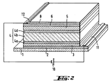
- the current leads 11, 12 in the form of strips placed at the opposite ends of the two electroconductive layers 2, 6 and electrically connected to a voltage generator 10.
- a tri-layer electrolyte which contains a layer 4b of cathodic electrochromic material which has been hydrated to ensure its proton conductivity and whose state has been blocked. insertion by placing it between two layers 4a, 4c both conductive protonic and insulating on the electronic plane.
- the degree of oxidation of the layer 4b is kept constant since it is electrically isolated from the two electroconductive layers 2, 6 of the system.
- the tri-layer electrolyte of the invention makes it possible to preserve the integrity of the "active" electrochromic materials of the system, and especially the integrity and durability of the layer of anodic electrochromic material 3 called counter-electrode.
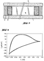
- the voltamogram of the figure 4 corresponds to the electrical behavior of the half-cell according to Example 1: it shows a correct functionality of the latter.
- the table below groups, according to the number of the cycle (n °), the quantity of inserted charges Q inx and thoroughinseche Q Cincinnati by the half-cell, in mC / cm 2 : cycle number Q dice Q lns 2 9.0 - 8.9 10 9.7 - 9.6 12 9.6 - 9.5 20 9.5 9.4
- the half-cell when submitting the half-cell to a potential of -0.4 volts relative to the saturated calomel electrode, the half-cell remains in the decolorized state. However, it is a potential value for which an electrochromic material such as tungsten oxide strongly blue. If it remains transparent, it is therefore that the layer of Ta 2 O 5 .nH 2 O electronically satisfactorily isolates it, blocking it in a discolored state.
- the half-cell made for comparison is immersed in the aqueous solution of H 3 PO 4 at 0.25 M, the half-cell thus lacks layers of Ta 2 O 5 and WO 3 which are hydrated. there is the almost immediate dissolution of the nickel oxide-based anode electrochromic material, and thus a total loss of functionality.
- This glazing is operated by imposing a potential of -1.4 V to impose the color and 0 V to cause discoloration of the system.
- the curve C 1 indicates the change in density of the current in mA / cm 2 as a function of time expressed in seconds.
- the curve C 2 indicates the variation of light transmission T L in% according to the illuminant D 65 also as a function of the time expressed in seconds.
- this example relates to an electrochromic glazing mirror function, the same structure as the figure 2 .
- the stack of layers is the same as in Example 3, except for two characteristics: here, the layer 4c hydrated tantalum oxide (which is actually optional) was removed and the thickness of the electroconductive layer 6 silver was increased to a thickness greater than 30 nm, for example d about 50 nm (it can be replaced by a layer of aluminum of the same thickness).
- the observer here views the glazing through the substrate 1 and its color change, since the first electroconductive layer 2 is transparent, the mirror reflecting effect being obtained by the second electroconductive layer 6 metal.
- the "solid" electrochromic glazings were mounted in double glazing, as shown very schematically in the figure 3 the substrate 1 carrying the stack of layers 2 to 8, not shown, is assembled to a second glass substrate 9 by means of a gas strip 15, so that the stack of layers is turned on the side of this gas blade.
- a metal spacer filled with particles for hygrometric control purpose 13 on which is placed a peripheral seal 14 of polysulfide and / or butyl rubber.
- Any electrochromic glazing assembly according to any one of the examples may be envisaged, especially in insulating multiple glazing and / or in laminated glazing.
- the "inhibited" electrochromic material can then completely replace the usual polymer electrolyte.
- the advantages are combined: the previous advantage, that is to say the preservation of the counter-electrode, and the advantage of a manufacture by successive deposits on the same substrate.
- Double-glazed as shown in figure 3 the all-solid glazing is particularly advantageous: the layers are protected, and the gain in terms of weight and bulk compared to a double glazing using electrochromic glazing with two substrates is obvious.
- the invention is simple to implement, insofar as the layer 4b specific to the invention is in a material generally of the type of those already used for their electrochromic properties, such as the tungsten oxide: even if it is necessary to correctly adjust the deposition conditions, in particular to possibly obtain the desired hydration level, it was already mastered before the invention the manufacture.
- the invention has in fact, in fact, unexpectedly conferred a second function on electrochromic materials which are often already known.
- the electrochromic glazing operates in transmission (examples 1 to 3) or in reflection (example 4), it is advantageous to adjust the characteristics of the layers that it uses to give it a given optical appearance.
- This adjustment of the optical characteristics of the glazing can also be carried out using complementary layers which may, for example, be inserted between substrates and electroconductive layers, or even be "outside" the electrochromic system, for example by being deposited on the other side of the glass substrate.
Landscapes
- Physics & Mathematics (AREA)
- Chemical & Material Sciences (AREA)
- Nonlinear Science (AREA)
- Chemical Kinetics & Catalysis (AREA)
- General Physics & Mathematics (AREA)
- Electrochemistry (AREA)
- Optics & Photonics (AREA)
- Inorganic Chemistry (AREA)
- Engineering & Computer Science (AREA)
- Organic Chemistry (AREA)
- General Chemical & Material Sciences (AREA)
- Geochemistry & Mineralogy (AREA)
- Life Sciences & Earth Sciences (AREA)
- Materials Engineering (AREA)
- Electrochromic Elements, Electrophoresis, Or Variable Reflection Or Absorption Elements (AREA)
- Secondary Cells (AREA)
- Battery Electrode And Active Subsutance (AREA)
- Laminated Bodies (AREA)
- Physical Vapour Deposition (AREA)
Description
La présente invention concerne le domaine des dispositifs électrochimiques comportant au moins une couche électrochimiquement active susceptible d'insérer réversiblement et simultanément des ions et des électrons, en particulier des dispositifs électrochromes. Ces dispositifs électrochimiques sont notamment utilisés pour fabriquer des vitrages dont la transmission lumineuse et/ou énergétique ou la réflexion lumineuse peuvent être modulées au moyen d'un courant électrique. Ceux-ci peuvent aussi être utilisés pour fabriquer des éléments de stockage d'énergie tels que des batteries ou encore des capteurs de gaz, ou des éléments d'affichage.The present invention relates to the field of electrochemical devices comprising at least one electrochemically active layer capable of reversibly and simultaneously inserting ions and electrons, in particular electrochromic devices. These electrochemical devices are used in particular to manufacture glazing whose light transmission and / or energy or light reflection can be modulated by means of an electric current. These can also be used to manufacture energy storage elements such as batteries or gas sensors, or display elements.
Si l'on prend l'exemple particulier des systèmes électrochromes, on rappelle que ces derniers, de manière connue, comportent une couche d'un matériau capable d'insérer de façon réversible et simultanée des cations et des électrons et dont les états d'oxydation correspondant aux états inséré et désinséré sont de coloration distincte, un des états étant généralement transparent. La réaction d'insertion ou de désinsertion est commandée par une alimentation électrique adéquate, notamment par application d'une différence de potentiel adaptée. Le matériau électrochrome, en général à base d'oxyde de tungstène, doit ainsi être mis en contact avec une source d'électrons telle qu'une couche électroconductrice transparente et une source de cations telle qu'un électrolyte conducteur ionique.If one takes the particular example of the electrochromic systems, it is recalled that the latter, in known manner, comprise a layer of a material capable of reversibly and simultaneously inserting cations and electrons and whose states of oxidation corresponding to the inserted and uninserted states are of distinct coloration, one of the states being generally transparent. The insertion or desinsertion reaction is controlled by a suitable power supply, in particular by applying a suitable potential difference. The electrochromic material, generally based on tungsten oxide, must be brought into contact with an electron source such as a transparent electroconductive layer and a cation source such as as an ionic conductive electrolyte.
Par ailleurs, il est connu que pour assurer au moins une centaine de commutations, il doit être associé à la couche de matériau électrochrome une contre-électrode capable elle aussi d'insérer de façon réversible des cations, symétriquement par rapport à la couche de matériau électrochrome de sorte que, macroscopiquement, l'électrolyte apparaît comme un simple médium des cations.Furthermore, it is known that to ensure at least one hundred switching operations, it must be associated with the electrochromic material layer a counterelectrode also capable of reversibly inserting cations, symmetrically with respect to the layer of material. electrochromically so that, macroscopically, the electrolyte appears as a simple medium of cations.
La contre-électrode doit être constituée ou d'une couche neutre en coloration ou du moins transparente quand la couche électrochrome est à l'état décoloré. L'oxyde de tungstène étant un matériau électrochrome cathodique, c'est-à-dire que son état coloré correspond à l'état le plus réduit, un matériau électrochrome anodique tel que l'oxyde de nickel ou l'oxyde d'iridium est généralement utilisé pour la contre-électrode. Il a également été proposé d'utiliser un matériau optiquement neutre dans les états d'oxydation concernés, comme par exemple l'oxyde de cérium ou des matériaux organiques comme les polymères conducteurs électroniques (polyaniline...) ou le bleu de Prusse.The counterelectrode must consist of a color neutral layer or at least a transparent layer when the electrochromic layer is in the faded state. The tungsten oxide being a cathodic electrochromic material, that is to say that its colored state corresponds to the most reduced state, an anode electrochromic material such as nickel oxide or iridium oxide is usually used for the counter electrode. It has also been proposed to use an optically neutral material in the oxidation states concerned, such as, for example, cerium oxide or organic materials such as electronically conductive polymers (polyaniline, etc.) or Prussian blue.
On trouvera la description de tels systèmes par exemple dans les brevets européens
Actuellement, on peut ranger ces systèmes dans deux catégories, selon le type d'électrolyte qu'ils utilisent :
- soit l'électrolyte se présente sous la forme d'un polymère ou d'un gel, par exemple un polymère à conduction protonique tel que ceux décrits dans le brevets européens
EP-0 253 713 EP-0 670 346 EP-0 382 623 EP-0 518 754 EP-0 532 408 - soit l'électrolyte est une couche minérale, conducteur ionique mais isolant électroniquement, on parle alors de systèmes électrochromes « tout solide ».
- the electrolyte is in the form of a polymer or a gel, for example a proton-conductive polymer such as those described in the European patents
EP-0 253 713 EP-0 670 346 EP-0 382 623 EP-0 518 754 EP-0 532 408 - either the electrolyte is a mineral layer, ionic conductor but electrically insulating, it is called "all solid" electrochromic systems.
Tous ces dispositifs électrochimiques autorisent une réversibilité satisfaisante des phénomènes d'insertion/désinsertion d'ions, donc des phénomènes de coloration/décoloration dans le cas spécifique des systèmes électrochromes. Toutefois, il est apparu que ce caractère de réversibilité avait tendance à se dégrader au cours du temps, notamment du fait d'une exposition prolongée à des rayons ultraviolets, ou à la chaleur (par exemple quand la température atteint 80°C) ou du fait d'un nombre élevé de commutations d'un état de coloration à un autre.All these electrochemical devices allow a satisfactory reversibility of the phenomena of insertion / de-insertion of ions, therefore of the phenomena of coloration / discoloration in the specific case of the systems Electrochromic. However, it has become apparent that this reversibility character tends to degrade over time, in particular due to prolonged exposure to ultraviolet light, or heat (for example when the temperature reaches 80 ° C.) or makes a large number of switches from one coloring state to another.
Ce problème a déjà été étudié dans le brevet
Cependant, cette solution présente des limites. En effet, compte-tenu de la nature, résultant principalement du mode de fabrication, des couches électroconductrices qui soutendent le dépôt des couches électrochimiquement actives, et principalement leur rugosité importante, on constate que cette couche-barrière doit être relativement épaisse pour jouer efficacement le rôle de protection de la contre-électrode qui lui est dévolu. Or, l'inconvénient d'une couche-barrière épaisse réside dans une perte partielle, ou même totale, de la fonctionnalité de l'ensemble du système, ou d'une partie du système, c'est-à-dire qu'elle ralentit ou même supprime les réactions réversibles d'insertion/désinsertion ionique au niveau d'une des couches ou des deux couches électrochimiquement actives.However, this solution has limitations. Indeed, given the nature, resulting mainly from the manufacturing method, electroconductive layers that support the deposition of electrochemically active layers, and mainly their high roughness, it is found that this barrier layer must be relatively thick to effectively play the protection role of the counter-electrode which is devolved to it. However, the disadvantage of a thick barrier layer lies in a partial or even total loss of the functionality of the whole system, or part of the system, that is to say that it slows or even suppresses reversible ion insertion / deinsertion reactions at one or both electrochemically active layers.
Le but de l'invention est alors de trouver un moyen pour augmenter la durabilité des systèmes électrochimiques à couches aptes à insérer réversiblement des ions, tout particulièrement des systèmes électrochromes, sans rencontrer l'inconvénient mentionné plus haut. Subsidiairement, l'invention se donne également pour objectif de simplifier la fabrication de tels systèmes.The object of the invention is then to find a means for increasing the durability of electrochemical systems with layers capable of reversibly inserting ions, especially electrochromic systems, without encountering the drawback mentioned above. In the alternative, the invention also aims to simplify the manufacture of such systems.
L'invention a pour objet un dispositif électrochimique comportant au moins un substrat, au moins une couche électroconductrice, au moins une couche électrochimiquement active susceptible d'insérer de manière réversible des ions, notamment des cations tels que H+, Li+, Na+, Ag+, K+ ou des anions du type OH-, et un électrolyte. Selon l'invention, cet électrolyte est une couche ou un empilement multicouche comprenant au moins une couche en un matériau conducteur ionique susceptible d'insérer de manière réversible les ions mais dont le degré d'oxydation global est maintenu essentiellement constant, couche que l'on désignera pour plus de clarté dans le reste de la description sous le terme de « couche A ».The subject of the invention is an electrochemical device comprising at least one substrate, at least one electroconductive layer, at least one electrochemically active layer capable of reversibly inserting ions, in particular cations such as H + , Li + , Na +. , Ag + , K + or anions of the OH - type, and an electrolyte. According to the invention, this electrolyte is a layer or a multilayer stack comprising at least one layer of an ionically conductive material capable of reversibly inserting the ions but whose overall degree of oxidation is kept substantially constant, which layer will be designated for clarity in the remainder of the description under the term "layer A".
Dans le contexte de l'invention, on comprend, pour cette couche A, sous le terme de « matériau susceptible d'insérer de manière réversible des ions » tout matériau ou association de matériaux à insertion électrochimique, ainsi que tout matériau ou association de matériaux dits « supercapacitifs » où les espèces chimiques restent en surface dudit matériau ou desdits matériaux, par effet électrostatique.In the context of the invention, it is understood, for this layer A, under the term "material capable of reversibly inserting ions" any material or combination of electrochemically inserted materials, as well as any material or combination of materials. so-called "supercapacitive" where the chemical species remain on the surface of said material or said materials, by electrostatic effect.
Toujours dans le contexte de l'invention, on comprend par « degré d'oxydation global » le degré d'oxydation du matériau ou de l'ensemble des matériaux constitutifs de la couche A, degré d'oxydation intégrant à la fois les effets de surface et les effets de volume.Again in the context of the invention, the term "overall oxidation state" is understood to mean the degree of oxidation of the material or of all the materials constituting the layer A, the degree of oxidation integrating both the effects of surface and volume effects.
De manière surprenante, les inventeurs ont ainsi eu recours à un matériau d'insertion ionique non seulement pour constituer la ou les couches électrochimiquement actives, ce qui était connu, mais aussi pour constituer tout ou partie de l'électrolyte du système. Utiliser un tel matériau en tant qu'électrolyte revient en quelque sorte à le détourner de sa fonction première habituelle : en le figeant dans un état d'insertion donné, en « inhibant » sa capacité à insérer réversiblement et simultanément des ions et des électrons, on n'exploite plus alors que ses propriétés de conduction/perméabilité ionique, et il s'est avéré qu'il jouait de façon très satisfaisante ce rôle d'électrolyte. En outre, comme cela sera détaillé ultérieurement à l'aide des exemples, le choix d'un tel matériau en tant qu'électrolyte ouvre de larges possibilités de mise en oeuvre, qui vont permettre d'augmenter significativement la durabilité/la durée de vie des dispositifs électrochimiques. Elles vont autoriser des configurations où les couches électrochimiquement actives, notamment celles qui jouent le rôle de contre-électrode, ne sont plus exposées à des dégradations du type réduction chimique irréversible ou pire, dissolution.Surprisingly, the inventors have thus used an ionic insertion material not only to constitute the electrochemically active layer or layers, which was known, but also to form all or part of the electrolyte of the system. Using such a material as an electrolyte amounts to somehow diverting it from its usual primary function: by locking it in a given insertion state, by "inhibiting" its ability to reversibly and simultaneously insert ions and electrons, it only uses its ionic conduction / permeability properties, and it turned out that it played a very satisfactory role in this role of electrolyte. In addition, as will be detailed later using the examples, the choice of such a material as an electrolyte opens wide possibilities of implementation, which will significantly increase the durability / service life electrochemical devices. They will allow configurations where the electrochemically active layers, in particular those that play the role of counter-electrode, are no longer exposed to irreversible chemical reduction type degradation or worse, dissolution.
Cependant, pour parvenir à empêcher que le matériau de cette couche A n'insère de façon réversible des ions, il est nécessaire de maintenir son degré d'oxydation global invariable. Pour ce faire, l'invention propose deux modes de réalisation non limitatifs, qui peuvent être soit alternatifs, soit cumulatifs.However, in order to prevent the material of this layer A from reversibly inserting ions, it is necessary to maintain its degree. invariable global oxidation. To do this, the invention provides two non-limiting embodiments, which can be either alternative or cumulative.
Selon un premier mode de réalisation, on isole électriquement la couche A vis-à-vis d'au moins une des sources d'électrons du dispositif, notamment en interposant au moins une couche d'un matériau isolant électroniquement (on comprend ici par « source d'électrons » soit une couche électrochimiquement active, soit une couche électroconductrice). De préférence, ces couches de matériau isolant électroniquement sont choisies de façon à être également conducteurs ioniques/perméables aux ions. De fait, elles peuvent alors faire partie de l'électrolyte au même titre que la couche A, l'électrolyte se trouvant dans ce cas sous la forme d'un empilement multicouches. Avantageusement, elles se trouvent alors disposées en contact direct avec au moins une des faces de la couche A.According to a first embodiment, the layer A is electrically insulated from at least one of the electron sources of the device, in particular by interposing at least one layer of an electronically insulating material (here it is understood by " electron source "is an electrochemically active layer or an electroconductive layer). Preferably, these layers of electronically insulating material are selected to be also ionic / ion-permeable conductors. In fact, they can then be part of the electrolyte in the same way as the layer A, the electrolyte being in this case in the form of a multilayer stack. Advantageously, they are then arranged in direct contact with at least one of the faces of the layer A.
Selon un second mode de réalisation, on maintient le degré d'oxydation global de la couche A constant en adaptant l'alimentation électrique aux bornes des couches électroconductrices du dispositif : il suffit d'ajuster l'alimentation pour conserver le potentiel électrique de la couche A à des valeurs qui soient hors de la plage de potentiels qui provoqueraient une variation du taux d'insertion ionique du matériau qui la constitue. Il reste ensuite à sélectionner de manière adéquate la nature de ce matériau et la nature du matériau de la ou des couche(s) électrochimiquement active(s) pour que cette plage de potentiels soit différente de la plage de potentiels permettant le fonctionnement du système, c'est-à-dire différente de la plage de potentiels permettant l'insertion/la désinsertion réversible des couches électrochimiquement actives.According to a second embodiment, the overall degree of oxidation of the layer A is maintained by adapting the power supply to the terminals of the electroconductive layers of the device: it is sufficient to adjust the power supply to conserve the electric potential of the layer A at values which are outside the range of potentials which would cause a variation of the ionic insertion rate of the material which constitutes it. It then remains to adequately select the nature of this material and the nature of the material of the electrochemically active layer (s) so that this range of potentials is different from the range of potentials allowing the operation of the system, that is to say different from the range of potentials allowing the reversible insertion / disinsertion of the electrochemically active layers.
Un exemple de configuration selon l'un ou l'autre des modes de réalisation décrits précédemment est réalisé par un dispositif électrochimique qui comporte successivement une couche électroconductrice, une couche électrochimiquement active susceptible d'insérer réversiblement des cations, notamment en un matériau électrochrome cathodique, un électrolyte comportant la couche A, éventuellement au moins une couche isolante électroniquement mais qui laisse passer les cations, une seconde couche électrochimiquement active susceptible d'insérer réversiblement des cations, notamment une couche de matériau électrochrome anodique, et enfin une couche électroconductrice.An exemplary configuration according to one or the other of the embodiments described above is carried out by an electrochemical device which successively comprises an electroconductive layer, an electrochemically active layer capable of reversibly inserting cations, in particular of a cathodic electrochromic material, an electrolyte comprising the layer A, optionally at least one electrically insulating layer but which passes the cations, a second electrochemically active layer capable of reversibly inserting cations, in particular a layer of anodic electrochromic material, and finally an electroconductive layer.
Avantageusement, le type de matériau choisi pour constituer la couche A est un matériau à propriété électrochrome, ce type de matériau pouvant également être choisi pour constituer les couches électrochimiquement actives du dispositif. Pour la couche A, il est préférable de bloquer le matériau électrochrome qui la constitue à l'état décoloré : de cette façon, sa coloration n'interfère pas avec la coloration variable des matériaux électrochromes des couches électrochimiquement actives. Mais on peut également choisir de le figer dans un état de coloration intermédiaire donné.Advantageously, the type of material chosen to constitute the layer A is a material with electrochromic property, this type of material may also be chosen to constitute the electrochemically active layers of the device. For layer A, it is preferable to block the electrochromic material which constitutes it in the bleached state: in this way, its coloration does not interfere with the variable coloration of the electrochromic materials of the electrochemically active layers. But one can also choose to freeze it in a given intermediate coloring state.
Pour que le matériau constitutif de la couche A soit un bon conducteur ionique, on peut avantageusement le choisir, dans le cas où le dispositif fonctionne par insertion réversible d'ions protons H+, sous la forme d'un oxyde ou d'un mélange d'oxydes métallique(s) qui peuvent être hydraté(s) ou non hydraté(s). On les choisit de préférence dans le groupe comprenant l'oxyde de tungstène éventuellement hydraté WO3.nH2O, l'oxyde de niobium éventuellement hydraté Nb2O5.nH2O, l'oxyde d'étain éventuellement hydraté SnO2.nH2O, l'oxyde de bismuth éventuellement hydraté Bi2O3.nH2O, l'oxyde de titane éventuellement hydraté TiO2-nH2O, l'oxyde de vanadium éventuellement hydraté V2O5-nH2O, l'oxyde de nickel éventuellement hydraté NiOxHy.nH2O, ou l'oxyde de molybdène éventuellement hydraté MoO3-nH2O, avec pour tous ces oxydes n ≥ O. Cet oxyde ou ce mélange d'oxydes peut également comporter un métal additionnel différent du métal majoritaire de l'oxyde, tel que le titane, le tantale ou le rhénium, tout particulièrement si l'on cherche à hydrater significativement l'oxyde : ces trois métaux ont tendance à faciliter l'hydratation de l'oxyde ou du mélange d'oxydes en question, hydratation souvent avantageuse pour assurer une conduction protonique satisfaisante. Pour favoriser cette hydratation, peuvent également être ajoutés comme additifs des alcalins du type Na, Li, K.For the material constituting the layer A to be a good ionic conductor, it can advantageously be chosen, in the case where the device functions by reversible insertion of proton ions H + , in the form of an oxide or a mixture of metal oxides which can be hydrated or not hydrated. They are preferably chosen from the group comprising the optionally hydrated tungsten oxide WO 3 .nH 2 O, the optionally hydrated niobium oxide Nb 2 O 5 .nH 2 O, the optionally hydrated tin oxide SnO 2 . nH 2 O, the optionally hydrated bismuth oxide Bi 2 O 3 .nH 2 O, the optionally hydrated titanium oxide TiO 2 -nH 2 O, the optionally hydrated vanadium oxide V 2 O 5 -nH 2 O, the optionally hydrated nickel oxide NiO x H y .nH 2 O, or the optionally hydrated molybdenum oxide MoO 3 -nH 2 O, for all these oxides n ≥ O. This oxide or mixture of oxides may also be have an additional metal different from the predominant metal of the oxide, such as titanium, tantalum or rhenium, especially if one seeks to hydrate the oxide significantly: these three metals tend to facilitate the hydration of the oxide or mixture of oxides in question, hydration often advantageous to ensure a conduction p satisfactory rotonic. To promote this hydration, may also be added as additives alkaline Na, Li, K.
Si, par contre, le dispositif fonctionne par insertion réversible d'ions lithium Li+, le matériau de la couche A doit cette fois laisser passer les ions lithium. On peut alors avantageusement le choisir à base d'un oxyde ou d'un mélange d'oxyde(s) métallique(s) lithiés ou non, notamment choisi(s) dans le groupe comprenant l'oxyde de nickel NiOx, l'oxyde de nickel lithié LiyNiOx, un mélange d'oxyde de titane et de cérium CeTiOx, l'oxyde de tungstène WO3, l'oxyde de niobium Nb2O5, l'oxyde de vanadium V2O5, l'oxyde de vanadium lithié LixV2O5.If, on the other hand, the device functions by reversible insertion of Li + lithium ions, the material of the layer A must this time pass the lithium ions. It can then advantageously be chosen based on an oxide or a mixture of oxide (s) metal (s) lithiated or not, especially selected (s) in the group comprising nickel oxide NiO x , nickel oxide lithium Li y NiO x , a mixture of titanium oxide and cerium CeTiO x , tungsten oxide WO 3 , niobium oxide Nb 2 O 5 , vanadium oxide V 2 O 5 , lithium vanadium oxide Li x V 2 O 5 .
En ce qui concerne le choix du matériau isolant électroniquement, il peut avantageusement être à base d'oxyde ou de mélange d'oxydes. On choisit par exemple parmi les oxydes d'un métal de la colonne Vb du tableau périodique, notamment l'oxyde de tantale, mais aussi parmi les oxydes appartenant au groupe comprenant l'oxyde d'antimoine Sb2O5, l'oxyde de zirconium ZrO2, l'oxyde de titane TiO2, l'oxyde de silicium SiO2, l'oxyde de chrome CrO3, l'oxyde de germanium GeO3. Il peut s'agir par exemple d'un oxyde mixte de tantale et de titane, d'oxyde de zinc sous la forme ZnO-(H3PO4)2.nH2O ou la forme hydratée de l'un quelconque des matériaux précédentes, ces derniers oxydes hydratés étant particulièrement adaptés pour des dispositifs fonctionnant par insertion réversible de protons.As regards the choice of the electronically insulating material, it may advantageously be based on an oxide or a mixture of oxides. For example, among the oxides of a metal of column Vb of the periodic table, in particular tantalum oxide, but also among the oxides belonging to the group comprising antimony oxide Sb 2 O 5 , the oxide of zirconium ZrO 2 , TiO 2 titanium oxide, SiO 2 silicon oxide, CrO 3 chromium oxide, GeO 3 germanium oxide. It can be for example a mixed oxide of tantalum and titanium, zinc oxide in the form ZnO- (H 3 PO 4 ) 2 .nH 2 O or the hydrated form of any of the materials previous, the latter hydrated oxides being particularly suitable for devices operating by reversible insertion of protons.
Ces matériaux peuvent en outre contenir des additifs favorisant leur hydrophilie, et donc augmentant leur taux d'hydratation. Ces additifs, qui ne représentent de préférence que quelques pourcents en poids de la couche, sont notamment des métaux tels que W, Re ou des alcalins du type Li, Na, K.These materials may further contain additives promoting their hydrophilicity, and thus increasing their rate of hydration. These additives, which preferably only represent a few percent by weight of the layer, are in particular metals such as W, Re or alkalis of the Li, Na, K type.
On peut aussi choisir des couches de matériau isolant électroniquement à base des composés ou de mélanges de composés suivants : CeF3, hexauranylphosphate HUP, MgF2, CaF2, SiOx, LiF, Na3AlF6, ou à base de Li3N, LiTaO3, LiAlF4, Li3PO4, LiPO2, LiN, LiNbO3, MgF2POLi, Li2WO4, cette dernière série de matériaux étant plus particulièrement adaptée à un fonctionnement du dispositif par insertion réversible d'ions lithium Li+. Que le dispositif fonctionne par insertion d'ions lithium ou de protons, notamment, on peut en fait également choisir les couches isolantes électroniquement telles qu'elles comportent un matériau devenu isolant électroniquement en bloquant sa capacité première à insérer des ions, par contrôle du potentiel de ces couches, il peut ainsi s'agir d'un matériau à base d'oxyde de tungstène.It is also possible to choose layers of electronically insulating material based on the following compounds or mixtures of compounds: CeF 3 , hexauranyl phosphate HUP, MgF 2 , CaF 2 , SiO x , LiF, Na 3 AlF 6 or Li 3 N , LiTaO 3 , LiAlF 4 , Li 3 PO 4 , LiPO 2 , LiN, LiNbO 3 , MgF 2 POLi, Li 2 WO 4 , this latter series of materials being more particularly adapted to an operation of the device by reversible insertion of lithium ions. Li + . Whether the device operates by insertion of lithium ions or protons, in particular, it is also possible to choose the electronically insulating layers such that they comprise a material that has become electronically insulating by blocking its primary capacity to insert ions, by controlling the potential of these layers, it can thus be a material based on tungsten oxide.
A noter également que les matériaux précédemment listés pour constituer la couche A, que le système fonctionne par insertion de ions Li+ ou H+, ainsi que les matériaux précédemment listés pour constituer le matériau isolant électroniquement, peuvent en outre être au moins partiellement nitruré(s) et/ou phosphaté(s). Quand les dépôts de ces couches s'effectuent par pulvérisation cathodique, on peut ainsi prévoir des pulvérisations réactives en présence, respectivement d'un certain taux de N2 et de PH3, ou toute molécule contenant respectivement au moins un atome d'azote et de phosphore.It should also be noted that the materials previously listed to constitute the layer A, that the system functions by insertion of Li + or H + ions, as well as the materials previously listed to constitute the material electronically insulating, can further be at least partially nitrided (s) and / or phosphaté (s). When the deposits of these layers are carried out by cathodic sputtering, it is thus possible to provide reactive sprays in the presence, respectively of a certain level of N 2 and PH 3 , or any molecule respectively containing at least one nitrogen atom and of phosphorus.
L'électrolyte multicouche de l'invention comprenant au moins la couche A peut également avantageusement comprendre au moins une couche d'un autre matériau conducteur ionique. Il peut s'agir d'une couche de liquide aqueux, tel que de l'eau additionnée d'acide sulfurique ou phosphorique dans le cas d'une insertion réversible de protons, d'une couche de liquide anhydre tel que du carbonate de propylène contenant un sel de lithium dans le cas d'une insertion réversible d'ions lithium. Il peut aussi s'agir d'une couche de gel ou de polymère, notamment des polymères conducteurs protoniques du type solution solide de polyoxyéthylène et d'acide phosphorique POE-H3PO4 (dans ce cas, le polymère constitue également un isolant électronique) ou encore à base d'un polymère obtenu par copolymérisation de trois précurseurs comprenant deux types de trialkoxysilanes greffés et un plastifiant présentant au moins un groupement urée. En tant que polymère conducteur d'ions lithium, on peut choisir un ionomère obtenu par neutralisation partielle d'acide polyacrylique, ou un polymère à base de polyéthylène imine branchée et d'un sel de lithium. Pour plus de détails sur la nature et la synthèse de tels produits polymériques, on se reportera avantageusement aux brevets cités en préambule à la présente demande.The multilayer electrolyte of the invention comprising at least the layer A may also advantageously comprise at least one layer of another ionically conductive material. It may be an aqueous liquid layer, such as water containing sulfuric or phosphoric acid in the case of a reversible insertion of protons, a layer of anhydrous liquid such as propylene carbonate containing a lithium salt in the case of a reversible insertion of lithium ions. It can also be a layer of gel or polymer, especially proton conductive polymers of the solid solution type of polyoxyethylene and phosphoric acid POE-H 3 PO 4 (in this case, the polymer also constitutes an electronic insulator or based on a polymer obtained by copolymerization of three precursors comprising two types of grafted trialkoxysilanes and a plasticizer having at least one urea group. As a lithium ion conductive polymer, it is possible to choose an ionomer obtained by partial neutralization of polyacrylic acid, or a polymer based on branched polyethylene imine and a lithium salt. For more details on the nature and the synthesis of such polymeric products, reference will advantageously be made to the patents cited in the preamble to the present application.
Selon l'invention, on peut également avantageusement envisager de superposer un certain nombre de multi-couches électrolytes telles que définies précédemment, notamment d'envisager un dédoublement : on peut ainsi favoriser la diminution des risques d'apparition de court-circuit surfacique dans le système. On peut ainsi avoir dans les systèmes de l'invention un multi-couche électrolyte « tout solide » dédoublé de type (NiOxHy-nH2O/WO3-nH2O)p ou (Ta2O5-nH2O/WO3-nH2O)p, avec p ≥ 2.According to the invention, it is also advantageous to superimpose a certain number of multi-layer electrolytes as defined above, in particular to envisage a doubling: it is thus possible to promote the reduction of the risks of appearance of a surface short circuit in the system. It is thus possible to have in the systems of the invention a multi-layer electrolyte "all solid" split type (NiO x H y -nH 2 O / WO 3 -nH 2 O) p or (Ta 2 O 5 -nH 2 O / WO 3 -nH 2 O) p , with p ≥ 2.
Venons-en maintenant à la nature des couches électrochimiquement actives du dispositif. Comme évoqué précédemment, on les choisit de préférence à propriété électrochrome et au nombre de deux, avec une couche de matériau électrochrome cathodique et une couche de matériau électrochrome anodique faisant fonction de contre-électrode.Let us come now to the nature of the electrochemically active layers of the device. As mentioned above, they are chosen from preferably electrochromic property and two, with a layer of cathodic electrochromic material and a layer of anodic electrochromic material acting as a counter-electrode.
Pour constituer la couche de matériau électrochrome cathodique, on peut choisir un matériau ou un mélange de matériaux choisi(s) dans le groupe comprenant l'oxyde de tungstène WO3, l'oxyde de molybdène MoO3, l'oxyde de vanadium V2O5, l'oxyde de niobium Nb2O5, l'oxyde de titane TiO2, un matériau « cermet » (association de matériau métallique et céramique, notamment sous la forme de particules métalliques dans une matrice céramique tel que WO3/Au ou WO3/Ag), un mélange d'oxydes de tungstène et de rhénium WO3/ReO3, l'acide phosphotungstique). Ces matériaux conviennent notamment dans le cas d'insertion réversible de protons et d'ions lithium. On peut aussi choisir des matériaux à base de métallophtalocyanine ou métallodibenzophtalocyanine de métaux de transition ou de terres rares.To form the cathodic electrochromic material layer, a material or a mixture of materials chosen from the group comprising tungsten oxide WO 3 , molybdenum oxide MoO 3 , vanadium oxide V 2 can be chosen. O 5 , niobium oxide Nb 2 O 5 , titanium oxide TiO 2 , a "cermet" material (combination of metallic and ceramic material, in particular in the form of metal particles in a ceramic matrix such as WO 3 / Au or WO 3 / Ag), a mixture of oxides of tungsten and rhenium WO 3 / ReO 3 , phosphotungstic acid). These materials are particularly suitable in the case of reversible insertion of protons and lithium ions. It is also possible to choose materials based on metallophthalocyanine or metallodibenzophthalocyanine of transition metals or rare earths.
Dans le cas où le dispositif fonctionne par insertion réversible de protons, on peut utiliser les mêmes matériaux, éventuellement sous forme hydratée.In the case where the device operates by reversible insertion of protons, one can use the same materials, optionally in hydrated form.
Pour constituer la couche de matériau électrochrome anodique, on peut choisir un matériau qui répond à la formule MxAyUz, avec M un métal de transition, A l'ion utilisé pour l'insertion réversible, par exemple un alcalin ou un proton, et U un chalcogène tel que l'oxygène, le soufre ou le sélénium Se.In order to form the layer of anodic electrochromic material, it is possible to choose a material which corresponds to the formula M x A y U z , with M a transition metal, to the ion used for the reversible insertion, for example an alkaline or a proton, and U a chalcogen such as oxygen, sulfur or selenium Se.
Il peut s'agir, notamment dans le cas d'une insertion d'ions protons H+, d'un composé ou d'un mélange de composés appartenant au groupe comprenant LiNiOx, IrOxHy, IrOxHyNz, NiOx, NiOxHz, NiOxHyNz, RhOx, CoOx, CrOx, MnOx.It may be, especially in the case of an insertion of proton ions H + , a compound or a mixture of compounds belonging to the group comprising LiNiO x , IrO x H y , IrO x H y N z , NiO x , NiO x H z , NiO x H y N z , RhO x , CoO x , CrO x , MnO x .
On peut aussi choisir des hydrures de terre rare, de lanthanide ou de métaux de transition MxHy, particulièrement dans le cas où le métal est l'Yttrium ou le lanthane. Dans le cas d'une insertion réversible d'ions lithium Li+, on choisit plutôt un composé ou un mélange de composés appartenant au groupe comprenant LiNiOx, LiMnzO4, IrOx, LixIrOy, NiOx, CeOx, TiOx, CeOx-TiOx, RhOx, CoOx, CrOx, MnOx, VOx, LixCoOy, LiCrOy, LixVOy, ReOx, RhOx, PtOx, FeOx, OsOx, CuOx, PrOx et tous ces matériaux sous forme lithiée. Dans le cas d'une insertion de protons ou d'ions lithium, on peut aussi choisir des matériaux à base d'hexacyanométalates, notamment de forme M[M'(CN)6], avec M et M' appartenant à la famille des métaux de transition et/ou des terres rares. On utilise plus particulièrement les « couples » M/M' suivants : Fe/Fe (composé également connu sous le nom de bleu de Prusse), Fe/Ru, Cu/Ru, Fe/Cr, Fe/Os, Cu/Os, Cr/Fe, Fe/Rn, ou encore les « couples » Ce/Fe, Pr/Fe, Nd/Fe, Sm/Fe, Eu/Fe, Gd/Fe, Tb/Fe, Dy/Fe, Ho/Fe, Er/Fe, Tm/Fe, Yb/Fe, Lu/Fe.It is also possible to choose rare earth, lanthanide or transition metal hydrides M x H y , particularly in the case where the metal is yttrium or lanthanum. In the case of a reversible insertion of Li + lithium ions, a compound or a mixture of compounds belonging to the group comprising LiNiO x , LiMn z O 4 , IrO x , Li x IrO y , NiO x , CeO x is preferably chosen. , TiO x , CeO x -TiO x , RhO x , CoO x , CrO x , MnO x , VO x , Li x CoO y , LiCrO y , Li x VO y , ReO x , RhO x , PtO x , FeO x , OsO x , CuO x , PrO x and all these materials in lithiated form. In the case of insertion of protons or lithium ions, one can also choose materials to based on hexacyanometalates, in particular of M [M '(CN) 6 ] form, with M and M' belonging to the family of transition metals and / or rare earths. The following "couples" M / M 'are more particularly used: Fe / Fe (also known as Prussian blue), Fe / Ru, Cu / Ru, Fe / Cr, Fe / Os, Cu / Os, Cr / Fe, Fe / Rn, or the "pairs" Ce / Fe, Pr / Fe, Nd / Fe, Sm / Fe, Eu / Fe, Gd / Fe, Tb / Fe, Dy / Fe, Ho / Fe, Er / Fe, Tm / Fe, Yb / Fe, Lu / Fe.
Qu'il s'agisse du matériau électrochrome cathodique ou du matériau électrochrome anodique, ces matériaux peuvent en outre être nitrurés au moins partiellement. On peut ainsi citer, en tant que matériau électrochrome cathodique WOxNx.Whether it is the cathodic electrochromic material or the anodic electrochromic material, these materials can also be nitrided at least partially. It is thus possible to cite as a cathodic electrochromic material WO x N x .
En ce qui concerne la nature des couches électroconductrices du dispositif, il y a deux variantes possibles : on peut avoir recours à des matériaux à base d'oxyde métallique dopé tels que de l'oxyde d'étain dopé au fluor SnO2:F ou l'oxyde d'indium dopé à l'étain ITO. On peut aussi utiliser des couches en métal ou en alliage métallique, par exemple à partir d'or Au, d'argent Ag ou d'aluminium Al. La couche métallique peut être déposée sur une couche plus fine métallique du type alliage Ni/Cr pour faciliter sa nucléation. Dans le cas le plus fréquent, le dispositif possède deux couches électroconductrices. Elles peuvent être soit toutes les deux métalliques, soit toutes les deux à base d'oxyde dopé, soit l'une à base de métal et d'autre à base d'oxyde dopé. Le choix peut notamment être dicté par l'application du dispositif électrochimique que l'on vise. On peut aussi avoir des superpositions de plusieurs couches électroconductrices. En outre, particulièrement dans le cas des systèmes dits « tout solide », la dernière couche électroconductrice (la plus éloignée du substrat sur lequel se sont effectués les dépôts des couches successives), peut être faite d'un empilement du type Au/WO3 ou NiCr/Au/WO3, la dernière couche en oxyde dur de type WO3 protégeant le reste de l'empilement, au moins de manière provisoire avant montage, pose d'un vernis protecteur, assemblage avec un second substrat, ... .With regard to the nature of the electroconductive layers of the device, there are two possible variants: doped metal oxide materials such as fluorinated tin oxide SnO 2 : F or indium oxide doped with tin ITO. It is also possible to use metal or metal alloy layers, for example from Au gold, Ag silver or Al aluminum. The metal layer may be deposited on a thinner metal layer of the Ni / Cr alloy type. to facilitate its nucleation. In the most frequent case, the device has two electroconductive layers. They can be either both metallic, or both based on doped oxide, either metal-based and doped oxide-based. The choice may in particular be dictated by the application of the electrochemical device that is aimed at. We can also have overlays of several electroconductive layers. In addition, particularly in the case of so-called "all solid" systems, the last electroconductive layer (the furthest away from the substrate on which the deposits of the successive layers have been made) can be made of a stack of the Au / WO 3 type. or NiCr / Au / WO 3 , the last hard oxide layer of WO 3 type protecting the rest of the stack, at least provisionally before mounting, a protective lacquer, assembly with a second substrate, etc. .
Ainsi, il peut être nécessaire que ces couches soient transparentes, notamment quand le dispositif est destiné à fonctionner en transmission, on préfère alors utiliser des couches à base d'oxyde ou des couches de métal de faible épaisseur. Mais on peut vouloir aussi faire fonctionner le dispositif en réflexion, et on peut alors judicieusement choisir l'une des couches électroconductrices transparente, notamment à base d'oxyde, et l'autre couche réfléchissante cette fois-ci plutôt en métal et choisie d'une épaisseur suffisante pour opacifier partiellement ou totalement le dispositif.Thus, it may be necessary for these layers to be transparent, especially when the device is intended to operate in transmission, it is then preferred to use oxide-based layers or thin metal layers. But we can also want to make the device work reflection, and then one can choose wisely one of the transparent electroconductive layers, including oxide-based, and the other reflective layer this time rather metal and selected a sufficient thickness to opacify partially or totally the device .
Avantageusement, selon une variante préférée de l'invention, l'électrolyte multicouche est choisi tel que l'ensemble des couches qui le constituent sont des couches de matériau solide. Avantageusement, l'ensemble des couches du dispositif est en fait à base de matériaux solides. Dans le contexte de l'invention, on entend par « matériau solide » tout matériau ayant la tenue mécanique d'un solide, en particulier tout matériau essentiellement minéral ou organique ou tout matériau hybride, c'est-à-dire partiellement minéral et partiellement organique, comme les matériaux que l'on peut obtenir par dépôt sol-gel à partir de précurseurs organo-minéraux. On a alors une configuration de système dit « tout solide » qui présente un avantage clair en termes de facilité de fabrication. En effet, quand le système contient un électrolyte sous forme de polymère qui n'a pas la tenue mécanique d'un solide, par exemple, cela contraint à fabriquer en fait, en parallèle, deux « demi-cellules » constituée chacune d'un substrat porteur revêtu d'une première couche électroconductrice puis d'une seconde couche électrochimiquement active, ces deux demi-cellules étant ensuite assemblées en insérant entre elles l'électrolyte. Avec une configuration « tout solide », la fabrication est simplifiée, puisque l'on peut déposer l'ensemble des couches du système, l'une après l'autre, sur un unique substrat porteur. On allège en outre le dispositif, puisqu'il n'est plus indispensable d'avoir deux substrats porteurs.Advantageously, according to a preferred variant of the invention, the multilayer electrolyte is chosen such that all the layers that constitute it are layers of solid material. Advantageously, all the layers of the device is in fact based on solid materials. In the context of the invention, the term "solid material" is understood to mean any material having the mechanical strength of a solid, in particular any essentially inorganic or organic material or any hybrid material, that is to say partially mineral and partially organic, as materials that can be obtained by sol-gel deposition from organo-mineral precursors. We then have a system configuration called "all solid" which has a clear advantage in terms of ease of manufacture. Indeed, when the system contains an electrolyte in the form of a polymer that does not have the mechanical strength of a solid, for example, it forces to manufacture in fact, in parallel, two "half-cells" each consisting of a carrier substrate coated with a first electroconductive layer and a second electrochemically active layer, these two half-cells are then assembled by inserting the electrolyte between them. With an "all solid" configuration, the manufacturing is simplified, since one can deposit all the layers of the system, one after the other, on a single carrier substrate. In addition, the device is lightened, since it is no longer necessary to have two carrier substrates.
Selon l'invention, on peut déposer tout ou partie des couches du dispositif électrochimique à l'aide de techniques sous vide du type pulvérisation cathodique, éventuellement assistée par champ magnétique et réactive, ou par évaporation éventuellement réactive, ou par des techniques impliquant la décomposition de précurseurs comme les techniques de pyrolyse ou de sol-gel. Si l'on reprend la configuration « tout solide » évoquée ci-dessus, on peut ainsi par exemple déposer sur un substrat toutes les couches par pulvérisation cathodique, le substrat défilant successivement dans des enceintes sous vide contenant l'atmosphère contrôlée et la cible adéquates.According to the invention, all or some of the layers of the electrochemical device can be deposited using vacuum techniques of the cathode sputtering type, possibly assisted by a magnetic and reactive field, or by possibly reactive evaporation, or by techniques involving decomposition. precursors such as pyrolysis or sol-gel techniques. If we take again the "all solid" configuration mentioned above, we can for example deposit on a substrate all the layers by sputtering, the substrate successively scrolling in vacuum enclosures containing the appropriate controlled atmosphere and the target .
L'invention concerne également toutes les applications du dispositif électrochimique qui a été décrit et qui sont notamment au nombre de quatre :
- → la première application concerne les vitrages électrochromes. Dans ce cas, avantageusement, on prévoit que le ou les substrat(s) du dispositif est (sont) transparent(s), en verre ou en plastique, quand les vitrages sont destinés à fonctionner en transmission lumineuse variable. Si on souhaite conférer au vitrage une fonction miroir, et le faire fonctionner en réflexion lumineuse variable, plusieurs solutions sont possibles : soit on choisit un des substrats opaque et réfléchissant (par exemple une plaque métallique), soit on associe le dispositif à un élément opaque et réfléchissant, soit on choisit une des couches électroconductrices du dispositif de nature métallique et suffisamment épaisse pour être réfléchissante.
Notamment quand le vitrage est destiné à fonctionner en transmission lumineuse variable, avec un dispositif muni d'un ou deux substrats transparents, on peut le monter en vitrage multiple, notamment en double-vitrage avec un autre substrat transparent, et/ou en vitrage feuilleté ; - → la seconde application concerne les éléments de stockage d'énergie, tout particulièrement les batteries, que l'on peut utiliser par exemple dans tous les appareils faisant intervenir des moyens électroniques et/ou informatiques, et tous les appareils nécessitant un dispositif de stockage d'énergie qui leur soit propre, autonome ou non ;
- → la troisième application concerne les capteurs de gaz,
- → la quatrième application concerne les systèmes d'affichage, où l'on juxtapose alors plusieurs systèmes électrochromes selon l'invention, par exemple sous forme de « damiers » de vitrages électrochromes commandés électriquement indépendamment les uns des autres. On peut ainsi former des écrans, panneaux d'informations ou publicitaires.
- → the first application concerns electrochromic glazings. In this case, advantageously, it is expected that the substrate (s) of the device is (are) transparent (s), glass or plastic, when the glazing is intended to operate in variable light transmission. If it is desired to confer on the glazing a mirror function, and to make it operate in variable light reflection, several solutions are possible: either one of the opaque and reflective substrates (for example a metal plate) is chosen, or the device is associated with an opaque element and reflecting, either one of the electroconductive layers of the device of a metallic nature is chosen and sufficiently thick to be reflective.
Particularly when the glazing is intended to operate in variable light transmission, with a device provided with one or two transparent substrates, it can be mounted in multiple glazing, in particular double glazing with another transparent substrate, and / or laminated glazing ; - The second application relates to energy storage elements, especially batteries, which can be used, for example, in all devices involving electronic and / or computer means, and all devices requiring a storage device; energy of their own, autonomous or not;
- → the third application concerns gas sensors,
- The fourth application concerns display systems, where several electrochromic systems according to the invention are then juxtaposed, for example in the form of "checkers" of electrochromic glazings electrically controlled independently of one another. It can thus form screens, information panels or advertising.
Si l'on revient à la première application, celle des vitrages électrochromes, ces derniers peuvent avantageusement être employés en tant que vitrages pour le bâtiment, par exemple vitrages feuilletés, multiples du type double-vitrage ou vitrage pariétodynamique, pour l'automobile, vitrages de véhicule industriel/de transport collectif, vitrages d'avion, vitrages ferroviaires, rétroviseurs, miroirs ou en tant qu'éléments d'optique tels que les objectifs d'appareil photographique, ou encore en tant que face avant ou élément à disposer sur ou à proximité de la face avant d'écrans de visualisation d'appareils tels que les ordinateurs ou les télévisions.If we return to the first application, that of electrochromic glazings, the latter can advantageously be used as glazing for the building, for example laminated glazing, multiple type double glazing or pariétodynamique glazing, for the automobile, glazing vehicles, railway glazings, mirrors, mirrors or optical elements such as camera lenses, or as a front panel or element to be placed on or near the front of display screens of devices such as computers or televisions.
Des modes de réalisation préférés de l'invention peuvent être de type :
- □ verre / couche(s) électroconductrice(s) / NiOxHy ou IrOxHy / [Ta2O5-nH2O/WO3-nH2O/POE-H3PO4] / WO3 / verre,
électrolyte multi-couches
les substrats en verre pouvant être remplacés par d'autres types de substrats, notamment à base de matériaux plastiques : - □ substrat couche électroconductrice /WO3/ [Ta2O5-nH2O ou Sb2O5-nH2O/WO3-nH2O/Sb2O5-nH2O ou Ta2O5-nH2O] couche(s) électroconductrice(s) / NiOxHy ou HxIrOy ou NilzOxHy ou IrSnzOxHy, un empilement équivalent au précédent, mais en substituant au multi-couche électrolyte à trois couches un multi-couche électrolyte de séquence :
- □ (NiOxHy-nH2O / WO3-nH2O)n, avec n ≥ 1, on illustre ainsi un type de multi-couche électrolyte à séquences répétées, notamment dédoublé.
- □ glass / electroconductive layer (s) / NiO x H y or IrO x H y / [Ta 2 O 5 -nH 2 O / WO 3 -nH 2 O / POE-H 3 PO 4 ] / WO 3 / glass,
multi-layer electrolyte
glass substrates that can be replaced by other types of substrates, in particular based on plastic materials: - □ electroconductive layer substrate / WO 3 / [Ta 2 O 5 -nH 2 O or Sb 2 O 5 -nH 2 O / WO 3 -nH 2 O / Sb 2 O 5 -nH 2 O or Ta 2 O 5 -nH 2 O] electroconductive layer (s) / NiO x H y or H x IrO y or Nil z O x H y or IrSn z O x H y , a stack equivalent to the preceding one, but substituting the multi-layer electrolyte to three layers a multi-layer electrolyte sequence:
- □ (NiO x H y -nH 2 O / WO 3 -nH 2 O) n , with n ≥ 1, thus illustrating a type of multi-layer electrolyte with repeated sequences, in particular split.
Les dispositifs de l'invention utilisés en tant que batterie peuvent aussi être employés dans le domaine du bâtiment ou des véhicules, ou faire partie d'appareils du type ordinateurs ou télévisions.The devices of the invention used as a battery can also be used in the field of the building or vehicles, or be part of devices such as computers or televisions.
En fait, les applications en tant que batteries des systèmes électrochimiques selon l'invention peuvent être très variées et particulièrement avantageuses, car, notamment dans le cas où l'on a recours à des systèmes « tout solide » peu encombrants, on peut aussi former des batteries solides, plates, non polluantes, (sans plomb, ni cadmium, ni liquide acide) et rechargeables. Si l'on a besoin de batteries particulièrement minces, on peut utiliser les systèmes de l'invention en « tout solide » et dont le ou les substrat(s) protecteur(s) des couches fonctionnelles peuvent être des substrats en matériau plastique souple et mince comme le polyéthylènetéréphtalate PET. On peut adapter ainsi des structures de système schématiquement de type :
- □ substrat plastique (PET) /couche métallique / couche électrochimiquement active / électrolyte multi-couches / couche électrochimiquement active / couche métallique / matériau protecteur.
- □ plastic substrate (PET) / metal layer / electrochemically active layer / multi-layer electrolyte / layer electrochemically active / metal layer / protective material.
Avec une telle structure, de telles batteries peuvent trouver application dans des véhicules, par exemple sous forme d'enroulement ou de couches superposées. On peut aussi les utiliser dans des cartes à puce électronique : elles permettent alors de conférer une fonction active à l'élément électronique de la carte (on peut les encapsuler dans l'épaisseur de la carte).With such a structure, such batteries can find application in vehicles, for example in the form of winding or superimposed layers. They can also be used in electronic smart cards: they then make it possible to confer an active function on the electronic element of the card (they can be encapsulated in the thickness of the card).
On peut aussi, de manière non exhaustive, citer d'autres applications à ces nouvelles batteries : les étiquettes auto-alimentées, les emballages « intelligents », les montres minces, tout appareil électronique auto-alimenté, des implants biologiques, des batteries en association avec des cellules solaires de type photovoltaïque pour stocker l'énergie, et tous les appareils électroménagers et domestiques.We can also, non-exhaustively, mention other applications to these new batteries: self-powered labels, "smart" packaging, thin watches, any self-powered electronic device, biological implants, batteries in combination with photovoltaic solar cells to store energy, and all household and domestic appliances.
On peut noter, toujours dans l'application batterie, que si l'on veut augmenter la valeur de la tension électrique délivrée par la batterie, on peut faire un montage consistant à en mettre au moins deux en série, la dernière couche électroconductrice du premier système étant confondue avec la première couche électroconductrice, en une couche qui est à la fois conductrice électroniquement et barrière ionique, notamment une couche (ou multi-couche) métallique du type Ag, Au et/ou alliage NiCr. Bien sûr, basé sur le même principe, on peut prévoir des montages en série de n systèmes avec n > 2.It may be noted, still in the battery application, that if it is desired to increase the value of the electrical voltage delivered by the battery, it is possible to make an assembly consisting in putting at least two in series, the last electroconductive layer of the first system being confused with the first electroconductive layer, in a layer which is both electronically conductive and ionic barrier, including a layer (or multi-layer) metal Ag, Au and / or NiCr alloy. Of course, based on the same principle, it is possible to plan series of n systems with n> 2.
On peut ainsi avoir un empilement de type :
- □ substrat /SnO2 :F / [WO3/Ta2O5-nH2O ou Sb2O5-nH2O/WO3-nH2O/IrOx/NiCr]n / substrat.
- □ substrate / SnO 2 : F / [WO 3 / Ta 2 O 5 -nH 2 O or Sb 2 O 5 -nH 2 O / WO 3 -nH 2 O / IrO x / NiCr] n / substrate.
(Ici et dans tout l'ensemble du présent texte, il faut comprendre que les couches électroconductrices du type SnO2:F peuvent être substituées par des couches d'autres oxydes métalliques dopés du type ITO ou par des couches métalliques de type Ag, Au, NiCr).(Here and throughout the present text, it is to be understood that the electroconductive layers of the SnO 2 : F type can be substituted by layers of other doped metal oxides of the ITO type or by Ag-type metal layers. , NiCr).
D'autres détails et caractéristiques avantageux de l'invention ressortent de la description faite ci-après en référence aux dessins annexés qui représentent :
- □
figure 1 : une représentation d'un premier mode de réalisation d'un vitrage électrochrome selon l'invention, - □
figure 2 : une représentation d'un second mode de réalisation d'un vitrage électrochrome selon l'invention, - □
figure 3 : une représentation d'un montage en double-vitrage du vitrage selon lafigure 2 , - □
figure 4 : un voltamogramme d'une demi-cellule d'un vitrage selon lafigure 1 , - □
figure 5 : une courbe de densité de courant lors d'une commutation d'un vitrage selon lafigure 2 .
- □
figure 1 : a representation of a first embodiment of an electrochromic glazing according to the invention, - □
figure 2 : a representation of a second embodiment of an electrochromic glazing according to the invention, - □
figure 3 : a representation of a double-glazed installation of the glazing according to thefigure 2 , - □
figure 4 : a voltammogram of a half-cell of a glazing according to thefigure 1 , - □
figure 5 : a current density curve when switching a glazing according to thefigure 2 .
Toutes ces figures sont extrêmement schématiques et ne respectent pas les proportions entre les différents éléments représentés, ceci afin d'en faciliter la lecture.All these figures are extremely schematic and do not respect the proportions between the various elements represented, in order to facilitate reading.
Les exemples non limitatifs concernent tous des vitrages électrochromes à insertion réversible de protons H+ et utilisant des substrats de verre silico-sodo-calcique clair de 4 mm d'épaisseur. Toutes les couches revêtant ces substrats qui sont à base de métal sont obtenues par pulvérisation cathodique assistée par champ magnétique en atmosphère inerte (Ar) à partir d'une cible du métal correspondant. Toutes les couches qui sont à base d'oxyde sont également obtenues par cette technique à partir d'une cible de métal, mais en atmosphère réactive contenant de l'oxygène, et éventuellement également de l'hydrogène et/ou de vapeur d'eau en cas d'oxyde obtenu sous forme hydratée. Toutes les couches à base d'oxyde fluoré tel que SnO2:F sont déposées soit par pulvérisation cathodique en atmosphère réactive contenant à la fois de l'oxygène et un gaz fluoré, soit par pyrolyse en phase solide ou gazeuse à partir de précurseurs du type organo-métalliques, de manière connue. Les couches de polymère sont obtenues par coulée. Il va de soi que l'invention n'est pas limitée à ces types de techniques de dépôt, et que toute autre technique peut être utilisée avec profit. Ainsi, les couches à base d'oxyde peuvent également être déposées par pyrolyse ou par sol-gel.The nonlimiting examples all relate to electrochromic glazings with reversible insertion of H + protons and using clear silico-soda-
Dans ces exemples, on ne rentrera pas dans le détail de l'alimentation électrique des vitrages. Elle est ici effectuée à l'aide d'un générateur de tension, comme représenté sous la référence 10 aux
L'exemple 1 concerne un vitrage électrochrome dont l'électrolyte contient un polymère, les exemples suivants concernent des vitrages électrochromes « tout solide ».Example 1 relates to an electrochromic glazing whose electrolyte contains a polymer, the following examples relate to "all solid" electrochromic glazings.
L'exemple 1 correspond au vitrage représenté à la
- → une première couche électroconductrice 2 en SnO2:
F de 300 nm, - → une première couche de matériau électrochrome anodique 3 en oxyde de nickel hydraté NiOxHy de 185 nm, (elle pourrait être remplacée par une couche en oxyde d'iridium hydraté)
- →
un électrolyte 4 se décomposant en une première couche 4a en oxyde de tantale hydraté Ta2O5.Hx de 100 nm, une seconde couche 4b en oxyde de tungstène hydraté WO3.Hx de 200 nm, une troisième couche 4c en solution solide de polyoxyéthylène avec de l'acide phosphorique POE-H3PO4 de 100 micromètres, - → une seconde couche 5 de matériau électrochrome cathodique à base d'oxyde de tungstène de 350 nm,
- → une seconde couche 6 de SnO2:
F de 300 nm puis un second substrat en verre 7.
- → a first electroconductive layer 2 in SnO 2 : F of 300 nm,
- → a first layer of anodic
electrochromic material 3 in hydrated nickel oxide NiO x H y 185 nm, (it could be replaced by a layer of hydrated iridium oxide) - An
electrolyte 4 decomposing into afirst layer 4a of tantalum oxide hydrate Ta 2 O 5 .H x of 100 nm, asecond layer 4b of hydrated tungsten oxide WO 3 .H x of 200 nm, a third layer 4c of solid solution of polyoxyethylene with phosphoric acid POE-H 3 PO 4 of 100 micrometers, - A
second layer 5 of cathodic electrochromic material based on tungsten oxide of 350 nm, - → a
second layer 6 of SnO 2 : F of 300 nm then asecond glass substrate 7.
Sont également représentées les amenées de courant 11, 12 sous forme de bandes placées aux extrémités opposées des deux couches électroconductrices 2, 6 et reliées électriquement à un générateur de tension 10.Also represented are the current leads 11, 12 in the form of strips placed at the opposite ends of the two
On a donc, conformément à l'invention, dans cet exemple un électrolyte tri-couche, qui contient une couche 4b en matériau électrochrome cathodique que l'on a hydraté pour s'assurer de sa conductivité protonique et dont on a bloqué l'état d'insertion en le disposant entre deux couches 4a, 4c toutes deux conductrices protoniques et isolantes sur le plan électronique. Ainsi, le degré d'oxydation de la couche 4b est maintenu constant, puisqu'elle se trouve isolée électriquement des deux couches électroconductrices 2, 6 du système.Thus, according to the invention, in this example a tri-layer electrolyte which contains a
Par rapport à un électrolyte qui ne contiendrait que la couche 4c de polymère POE-H3PO4, l'électrolyte tri-couche de l'invention permet de préserver l'intégrité des matériaux électrochromes « actifs » du système, et tout particulièrement l'intégrité et la durabilité de la couche de matériau électrochrome anodique 3 appelée contre-électrode.With respect to an electrolyte which contains only the 4c layer of POE-H 3 PO 4 polymer, the tri-layer electrolyte of the invention makes it possible to preserve the integrity of the "active" electrochromic materials of the system, and especially the integrity and durability of the layer of anodic
Pour évaluer cette durabilité améliorée, on a fait le test suivant : on a réalisé une « demi-cellule » selon l'exemple 1 c'est-à-dire qu'on a réalisé l'empilement :
- verre (1) / SnO2:F (2) / NiOxHy (3) / Ta2O5.Hx (4a) / WO3.Hx (4b)
- glass (1) / SnO 2 : F (2) / NiO x H y (3) / Ta 2 O 5 .H x (4a) / WO 3 .H x (4b)
En parallèle, à titre de comparaison, on a réalisé l'empilement :
- verre (1) / SnO2:F (2) / NiOxHy (3)
- glass (1) / SnO 2 : F (2) / NiO x H y (3)
On a fait cycler ensuite de -1,4 à + O volt ces deux demi-cellules dans une solution aqueuse contenant H3PO4 dans une concentration 0,25 M, avec comme référence une électrode au calomel saturé.These two half-cells were then cycled from -1.4 to + 0 volts in an aqueous solution containing H 3 PO 4 in a 0.25 M concentration, with a saturated calomel electrode as reference.
Le voltamogramme de la
On vérifie bien que, quelque soit le nombre de cycles effectué, on a une quasi-constance dans le nombre de charges insérées ou désinsérées par cycle, ce qui prouve la bonne reproductibilité de la commutation du matériau électrochrome anodique d'un état d'oxydation à un autre. Ce matériau conserve ainsi son intégrité dans un milieu hautement acide, ce qui montre que la « portion » d'électrolyte Ta2O5.nH2O/WO3.nH2O le protège de manière efficace.It is verified that, whatever the number of cycles carried out, there is a quasi-constancy in the number of charges inserted or deinserted per cycle, which proves the good reproducibility of the switching of the anode electrochromic material of an oxidation state. to another. This material thus retains its integrity in a highly acidic medium, which shows that the "portion" of electrolyte Ta 2 O 5 .nH 2 O / WO 3 .nH 2 O protects it effectively.
Par ailleurs, quand on soumet la demi-cellule à un potentiel de -0,4 volt par rapport à l'électrode au calomel saturé, la demi-cellule reste à l'état décoloré. Or c'est une valeur de potentiel pour laquelle un matériau électrochrome tel que l'oxyde de tungstène bleuit fortement. S'il reste transparent, c'est donc que la couche de Ta2O5.nH2O l'isole électroniquement de façon satisfaisante, le bloquant dans un état décoloré.Moreover, when submitting the half-cell to a potential of -0.4 volts relative to the saturated calomel electrode, the half-cell remains in the decolorized state. However, it is a potential value for which an electrochromic material such as tungsten oxide strongly blue. If it remains transparent, it is therefore that the layer of Ta 2 O 5 .nH 2 O electronically satisfactorily isolates it, blocking it in a discolored state.
Par contre, si l'on plonge la demi-cellule faite à titre de comparaison, dans la solution aqueuse d'H3PO4 à 0,25 M, demi-cellule dépourvue donc de couches en Ta2O5 et WO3 hydratés, on constate la dissolution quasi-immédiate du matériau électrochrome anodique à base d'oxyde de nickel, et donc une perte totale de fonctionnalité.On the other hand, if the half-cell made for comparison is immersed in the aqueous solution of H 3 PO 4 at 0.25 M, the half-cell thus lacks layers of Ta 2 O 5 and WO 3 which are hydrated. there is the almost immediate dissolution of the nickel oxide-based anode electrochromic material, and thus a total loss of functionality.
Cet exemple correspond à un vitrage non représenté. Il est constitué d'un unique substrat en verre sur lequel on a déposé l'une après l'autre toutes les couches du système, soit :
- → une couche électroconductrice en SnO2:
F de 300 nm, - → une couche de matériau électrochrome cathodique en oxyde de tungstène de 380 nm,
- → un électrolyte bi-couche se décomposant en une couche d'oxyde de tantale hydraté Ta2O5.nH2O de 18 nm et une couche d'oxyde de tungstène hydraté WO3.nH2O de 200 nm (Il n'y a pas de troisième couche ici, mais elle peut aussi être prévue et être à base de Ta2O5-nH2O comme la première couche),
- → une couche de matériau électrochrome anodique à base d'oxyde d'iridium hydraté HxIrOy de 45 nm, (elle peut être remplacée par de l'oxyde de nickel hydraté),
- → une couche électroconductrice en
ITO de 200 nm.
- An electroconductive SnO 2 : F layer of 300 nm,
- A layer of cathodic electrochromic material made of 380 nm tungsten oxide,
- A bi-layer electrolyte decomposing into a layer of hydrated tantalum oxide Ta 2 O 5 .nH 2 O of 18 nm and a hydrated tungsten oxide layer WO 3 .nH 2 O of 200 nm (II n ' there is no third layer here, but it can also be planned and be based on Ta 2 O 5 -nH 2 O as the first layer),
- A layer of anodic electrochrome material based on hydrated iridium oxide H x IrO y of 45 nm, (it may be replaced by hydrated nickel oxide),
- An electroconductive ITO layer of 200 nm.
On fait fonctionner ce vitrage en imposant un potentiel de -1,4 V pour imposer la coloration et de 0 V pour provoquer la décoloration du système. On a représenté en
Le vitrage fonctionne de façon tout-à-fait satisfaisante.The glazing works quite satisfactorily.
Cet exemple correspond au vitrage représenté en
- → une couche électroconductrice 2 en ITO ou en SnO2:
F de 300 nm, - → une couche 3 en matériau électrochrome cathodique en oxyde de tungstène WO3,
- →
un électrolyte 4 tri-couche composé d'une couche 4a d'oxyde de tantale hydraté, d'une couche 4b d'oxyde de tungstène hydraté d'épaisseur identique aux mêmes couches selon l'exemple précédent, et en plus une couche 4d en oxyde de tantale hydraté similaire à la couche 4a et d'épaisseur 18 nm, - → une couche 5 en matériau électrochrome anodique en oxyde de nickel NiOx d'épaisseur d'environ 200 nm ou en oxyde d'iridium IrOx d'épaisseur environ 50 nm, ces oxydes étant éventuellement hydratés,
- → une couche 6 électroconductrice en argent de 10 nm,
- → un
ensemble de couches 8 visant à protéger la couche sous-jacente d'argent, notamment vis-à-vis de l'oxydation. Il s'agit de préférence d'une mince couche de NiCr de 1 à 3 nm d'épaisseur surmontée d'une couche de matériau par exemple diélectrique, notamment à base d'oxyde tel que l'oxyde d'étain, d'une épaisseur comprise entre 20 et 50 nm. (La couche de NiCr permet de protéger de l'oxydation la couche d'argent lors du dépôt de la couche en SnO2 par pulvérisation cathodique en présence d'oxygène. Elle est donc, dans le vitrage final, partiellement ou totalement oxydée). Une seconde couche de NiCr peut aussi être éventuellement intercalée entre la couche d'argent 6 et la couche électrochimiquement active 5.
- An electroconductive layer 2 made of ITO or SnO 2 : F of 300 nm,
- A
layer 3 made of cathodic electrochromic material made of tungsten oxide WO 3 , - A
tri-layer electrolyte 4 composed of alayer 4a of hydrated tantalum oxide, alayer 4b of hydrated tungsten oxide of identical thickness to the same layers according to the preceding example, and in addition alayer 4d tantalum oxide hydrate similar to thelayer 4a and 18 nm thick, - A
layer 5 of nickel oxide electrochromic anode material NiO x with a thickness of about 200 nm or iridium oxide IrO x with a thickness of about 50 nm, these oxides being optionally hydrated, - A 10 nm
electroconductive silver layer 6, - → a set of
layers 8 to protect the underlying layer of silver, especially with respect to oxidation. It is preferably a thin layer of NiCr 1 to 3 nm thick surmounted by a layer of material for example dielectric, in particular oxide-based oxide such as tin oxide, a thickness between 20 and 50 nm. (The NiCr layer makes it possible to protect the silver layer from oxidation during the deposition of the SnO 2 layer by cathodic sputtering in the presence of oxygen, so that it is partially or completely oxidized in the final glazing). A second layer of NiCr may also be optionally interposed between thesilver layer 6 and the electrochemicallyactive layer 5.
Alors que les exemples précédents fonctionnaient en transmission, en utilisant des couches électroconductrices essentiellement transparentes car soit en oxyde, soit en métal mais alors très minces, cet exemple concerne un vitrage électrochrome à fonction miroir, de même structure qu'à la
L'observateur regarde ici le vitrage à travers le substrat 1 et sa modification de couleur, puisque la première couche électroconductrice 2 est transparente, l'effet réfléchissant miroir étant obtenu par la seconde couche électroconductrice 6 métallique.The observer here views the glazing through the substrate 1 and its color change, since the first electroconductive layer 2 is transparent, the mirror reflecting effect being obtained by the
On a monté les vitrages électrochromes « tout solide » en double-vitrage, comme représenté très schématiquement à la
Tout assemblage de vitrage électrochrome selon l'un quelconque des exemples peut être envisagé, notamment en vitrage multiple isolant et/ou en vitrage feuilleté. On pourra se reporter par exemple au brevet
De cette série d'exemples, on peut tirer les conclusions suivantes.From this series of examples, the following conclusions can be drawn.
Si l'on souhaite conserver un électrolyte sous forme de polymère dans lequel on a dissout un acide fort comme H3PO4, ce qui est le cas de l'exemple 1 , l'invention en « complétant » cet électrolyte par un matériau électrochrome « inhibé » et par une couche d'oxyde hydraté, a trouvé une solution très efficace pour prévenir la dégradation de la contre-électrode en matériau électrochrome anodique.If it is desired to retain an electrolyte as a polymer in which a strong acid was dissolved as H 3 PO 4, which is the case of Example 1, the invention in "completing" the electrolyte by an electrochromic material "Inhibited" and by a hydrated oxide layer, found a very effective solution to prevent the degradation of the electrode against anodic electrochromic material.
Si, au contraire, on préfère passer à un système tout solide, ce qui est le cas des autres exemples, le matériau électrochrome « inhibé » peut alors se substituer complètement à l'électrolyte polymère habituel. En l'isolant électroniquement de l'une au moins des sources d'électrons, on cumule aux avantages : l'avantage précédent, c'est-à-dire la préservation de la contre-électrode, et l'avantage d'une fabrication par dépôts successifs sur un même substrat. Monté en double-vitrage comme montré à la
Il est aussi important de souligner que l'invention est simple de mise en oeuvre, dans la mesure où la couche 4b spécifique à l'invention est en un matériau en général du type de ceux déjà utilisés pour leurs propriétés électrochromes, tel que l'oxyde de tungstène : même s'il est nécessaire d'ajuster correctement les conditions de dépôt, notamment pour obtenir éventuellement le taux d'hydratation recherché, on en maîtrisait déjà avant l'invention la fabrication. L'invention a surtout en fait conféré, de manière inattendue, une seconde fonction à des matériaux électrochromes souvent déjà connus.It is also important to emphasize that the invention is simple to implement, insofar as the
En dernier lieu, que le vitrage électrochrome fonctionne en transmission (exemples 1 à 3) ou en réflexion (exemple 4), on peut avantageusement ajuster les caractéristiques des couches qu'il utilise pour lui conférer un aspect optique donné. Ainsi, on peut moduler les indices de réfraction et/ou les épaisseurs des couches à base de métal ou d'oxyde pour obtenir un vitrage qui va commuter dans une plage de transmission lumineuse donnée, qui va avoir un aspect plus ou moins réfléchissant ou une colorimétrie donnée.Finally, whether the electrochromic glazing operates in transmission (examples 1 to 3) or in reflection (example 4), it is advantageous to adjust the characteristics of the layers that it uses to give it a given optical appearance. Thus, it is possible to modulate the refractive indices and / or the thicknesses of the metal or oxide-based layers to obtain a glazing that will switch in a given light transmission range, which will have a more or less reflective appearance or a given colorimetry.
Cet ajustement des caractéristiques optiques du vitrage peut également être effectué à l'aide de couches complémentaires qui peuvent, par exemple, être insérées entre substrats et couches électroconductrices, ou même être « extérieures » au système électrochrome, par exemple en étant déposées sur l'autre face du substrat verrier.This adjustment of the optical characteristics of the glazing can also be carried out using complementary layers which may, for example, be inserted between substrates and electroconductive layers, or even be "outside" the electrochromic system, for example by being deposited on the other side of the glass substrate.
Claims (16)
- Electrochemical device which includes at least one substrate (1, 7), and which includes, in succession, an electronically conductive layer (2), an electrochemically active layer (3) capable of reversibly injecting cations, an electrolyte (4) which includes a layer (4b) made of ionically conductive material capable of reversibly injecting the cations but whose overall degree of oxidation is maintained essentially constant, and at least one electronically insulating layer (4a, 4c), a second electrochemically active layer (5) capable of reversibly injecting cations, and an electronically conductive layer (6),
characterized in that in which the overall degree of oxidation of the layer (4b) of the electrolyte (4) is maintained essentially constant by electrically isolating the said layer (4b) from at least one of the electron sources of the device by interposing at least one layer (4a, 4d) of an electronically insulating material, the layer(s) (4a, 4d) made of electronically insulating material also being ionically conductive/ion-permeable, the material of the layer (4b) capable of reversibly injecting the ions but whose degree of oxidation is maintained essentially constant being a material exhibiting an electrochromic property maintained in the decoloured state or in an intermediate state of coloration. - Electrochemical device according to Claim 1, characterized in that the layer(s) (4a, 4d) made of electronically insulating material is in direct contact with at least one of the faces of the layer (4b) having an overall degree of oxidation maintained essentially constant.
- Electrochemical device according to one of the preceding claims, characterized in that the overall degree of oxidation of the layer (4b) of the electrolyte (4) is maintained essentially constant by keeping the potential of the said layer (4b) at values outside the range of potentials causing a variation in the degree of ion injection of the material of which it is composed.
- Electrochemical device according to one of the preceding claims, characterized in that it operates by reversible injection of protons from the electrochemically active layer or layers (3, 5) and in that the material of the layer (4b) of the electrolyte (4) capable of reversibly injecting protons but whose degree of oxidation is maintained essentially constant is based on a metal oxide or a mixture of metal oxides, optionally this or these being hydrated and especially chosen from the group comprising tungsten oxide, optionally hydrated, WO3·nH2O, niobium oxide, optionally hydrated, Nb2O5·nH2O, nickel oxide, optionally hydrated, NiOxHy·nH2O, tin oxide, optionally hydrated, SnO2·nH2O, bismuth oxide, optionally hydrated, Bi2O3·nH2O, titanium oxide, optionally hydrated, TiO2·nH2O, vanadium oxide, optionally hydrated, V2O5·nH2O, molybdenum oxide, optionally hydrated, MoO3·nH2O4 where n ≥ 0 and optionally comprising an additive metal favouring hydration, in the form of an additional metal such as titanium, tantalum or rhenium, or of an alkali metal of the Na, Li or K type.
- Electrochemical device according to one of Claims 1 to 3, characterized in that it operates by reversible injection of lithium ions Li+ from the electrochemically active layer or layers (3, 5) and in that the material of the layer (4b) of the electrolyte (4) capable of reversibly injecting lithium ions Li+ but whose degree of oxidation is maintained essentially constant is based on a metal oxide or a mixture of metal oxides which may or may not be lithiated, it (they) being especially chosen from the group comprising nickel oxide NiOx, lithiated nickel oxide LiyNiOx, a mixture of titanium and cerium oxides CeTiOx, tungsten oxide WO3, niobium oxide Nb2O5, vanadium oxide V2O5 and lithiated vanadium oxide LixV2O5.
- Electrochemical device according to one of the preceding claims, characterized in that the layer or layers (4a, 4d) of electronically insulating material includes (include) at least one oxide of a metal from column VB of the Periodic Table, especially tantalum oxide Ta2O5, but also at least one metal oxide belonging to the group comprising antimony oxide Sb2O5, zirconium oxide ZrO2, titanium oxide TiO2, silicon oxide SiO2, chromium oxide CrO3, especially a mixed tantalum-titanium oxide, germanium oxide GeO3, ZnO(H3PO4)2·nH2O, all these oxides being optionally hydrated and optionally comprising an additive favouring their hydration, such as a metal of the W, Re type or an alkali metal of the Li, Na, K type.
- Electrochemical device according to one of the preceding claims, characterized in that the layer(s) (4a, 4c) of electronically insulating material are based on CeF3, hexauranylphosphate HUP, MgF2, CaF2, SiOx, LiF, Na3AlF6, or based on Li3N, LiTaO3, LiAlF4, Li3PO4, LiPO2, LiN, LiNbO3, MgF2POLi or Li2WO4 more particularly in the case in which the device operates by reversible injection of lithium ions from the electrochemically active layer or layers (3, 5).
- Electrochemical device according to one of the preceding claims, characterized in that the materials forming the layer (4b) capable of reversibly injecting the ions but whose degree of oxidation is maintained essentially constant and/or the materials forming the layer(s) (4a, 4d) made of electronically insulating material are nitrided and/or phosphatized.
- Electrochemical device according to one of the preceding claims, characterized in that the electrochemically active layer(s) (3, 5) comprise a layer (5) of cathodic electrochromic material such as tungsten oxide WO3, molybdenum oxide MoO3, vanadium oxide V2O5, niobium oxide Nb2O5, titanium oxide TiO2, a cermet material of the WO3/Au or WO3/Ag type, a mixture of tungsten and rhenium oxides WO3/ReO3, phosphotungstic, metallophthalocyanines or metallodibenzophthalocyanines of transition metals or of rare earths, optionally nitrided, especially in the case in which the device operates by reversible injection of lithium ions Li+ or protons, and the same materials optionally hydrated in the case in which the device operates especially by reversible injection of protons H+.
- Electrochemical device according to one of the preceding claims, characterized in that the electrochemically active layer(s) comprise a layer (3) of anodic electrochromic material in the form MxAyUz, where M is a transition metal, A is the ion used for the reversible injection, i.e. an alkali metal or a proton, and U is a chalcogenide such as S, O or Se, optionally nitrided.
- Electrochemical device according to one of the preceding claims, characterized in that the electrochemically active layer(s) comprise a layer (3) of anodic electrochromic material which is chosen, in the case of reversible injection of protons, from the group comprising LiNiOx, IrOxHy, IrOxHyNz, NiOx, NiOxH2, NiOxHyNz, RhOx, CoOx, CrOx, MnOx, and a hydride of a rare earth, of a lanthanide or of transition metals and, in the case of reversible injection of lithium ions Li+, from the group comprising LiNiOx, LiMn2O4, IrOx, LixIrOy, NiOx, CeOx, TiOx, CeOx-TiOx, RhOx, CoOx, CrOx, MnOx, VOx, Lix, CoOy, LiCrOy, LixVOy, ReOx, RhOx, PtOx, FeOx, OsOy, CuOx, PrOx, these compounds being optionally lithiated and/or nitrided, and, in the case of injection of protons or of Li+ or of hexacyanometalates, especially of formula M[M'(CN)6], with M and M' being transition metals and/or rare earths.
- Electrochemical device according to one of the preceding claims, characterized in that at least one of the electronically conductive layer(s) (2, 6) is based on at least one doped metal oxide, such as ITO or F:SnO2, or based on a metal or on metal alloys such as gold, silver, aluminium or Ni-Cr alloy or on the superposition of several layers of these materials.
- Electrochromic glazing, characterized in that it includes the electrochemical device according to one of the preceding claims.
- Electrochromic glazing according to Claim 13, characterized in that it has a variable light transmission coefficient, with the essentially transparent substrate or both substrates (1, 7) made of glass or of plastic.
- Electrochromic glazing according to Claim 13, characterized in that it has a mirror function, either by combining the electrochemical device with a reflecting element, or by choosing a reflecting opaque substrate, or by choosing one of the electronically conductive metal layers (2, 6) sufficiently thick to be reflecting.
- Electrochromic glazing according to either of Claims 13 and 14, characterized in that it comprises the electrochemical device comprising one or two transparent or barely absorbent substrates (1, 7) mounted as double glazing or as a parietodynamic window using another transparent substrate (9).
Applications Claiming Priority (2)
| Application Number | Priority Date | Filing Date | Title |
|---|---|---|---|
| FR9603799 | 1996-03-27 | ||
| FR9603799A FR2746934B1 (en) | 1996-03-27 | 1996-03-27 | ELECTROCHEMICAL DEVICE |
Publications (2)
| Publication Number | Publication Date |
|---|---|
| EP0867752A1 EP0867752A1 (en) | 1998-09-30 |
| EP0867752B1 true EP0867752B1 (en) | 2013-12-11 |
Family
ID=9490588
Family Applications (1)
| Application Number | Title | Priority Date | Filing Date |
|---|---|---|---|
| EP97400702.3A Expired - Lifetime EP0867752B1 (en) | 1996-03-27 | 1997-03-27 | Electrochromic device |
Country Status (6)
| Country | Link |
|---|---|
| US (3) | US6277523B1 (en) |
| EP (1) | EP0867752B1 (en) |
| JP (1) | JP4156685B2 (en) |
| KR (1) | KR100526640B1 (en) |
| CA (1) | CA2201036A1 (en) |
| FR (1) | FR2746934B1 (en) |
Cited By (1)
| Publication number | Priority date | Publication date | Assignee | Title |
|---|---|---|---|---|
| US8637349B2 (en) | 2000-03-24 | 2014-01-28 | Cymbet Corporation | Method and apparatus for integrated-circuit battery devices |
Families Citing this family (170)
| Publication number | Priority date | Publication date | Assignee | Title |
|---|---|---|---|---|
| FR2746934B1 (en) * | 1996-03-27 | 1998-05-07 | Saint Gobain Vitrage | ELECTROCHEMICAL DEVICE |
| FR2753545B1 (en) * | 1996-09-18 | 1998-10-16 | Saint Gobain Vitrage | ELECTROCHEMICAL DEVICE |
| JP4460078B2 (en) * | 1996-10-17 | 2010-05-12 | サン−ゴバン グラス フランス | Glazing assembly |
| FR2791147B1 (en) * | 1999-03-19 | 2002-08-30 | Saint Gobain Vitrage | ELECTROCHEMICAL DEVICE OF THE ELECTROCOMMANDABLE DEVICE TYPE WITH VARIABLE OPTICAL AND / OR ENERGY PROPERTIES |
| US6676021B1 (en) * | 1999-04-14 | 2004-01-13 | Power Paper Ltd. | Authenticated cards |
| FR2793888B1 (en) * | 1999-05-20 | 2002-06-28 | Saint Gobain Vitrage | ELECTROCHEMICAL DEVICE |
| US6515787B1 (en) * | 2000-03-07 | 2003-02-04 | Eclipse Energy Systems, Inc. | Electrochromic layer |
| FR2809388B1 (en) | 2000-05-23 | 2002-12-20 | Saint Gobain Vitrage | GLAZING COMPRISING AT LEAST ONE LAYER WITH THERMOCHROMIC PROPERTIES |
| FR2811778B1 (en) | 2000-07-13 | 2003-06-20 | Saint Gobain | ELECTROCHEMICAL DEVICE OF THE ELECTROCHROMIC TYPE OR PHOTOVOLTAIC DEVICE AND ITS ELECTRICAL CONNECTION MEANS |
| US6561460B2 (en) | 2000-08-03 | 2003-05-13 | Ppg Industries Ohio, Inc. | Switchable electrochromic devices for use in aircraft transparency windows |
| FR2815374B1 (en) * | 2000-10-18 | 2003-06-06 | Saint Gobain | SHEET GLAZING AND ITS MEANS FOR PERIPHERAL SEALING |
| FR2821937B1 (en) * | 2001-03-07 | 2003-06-06 | Saint Gobain | ELECTRICALLY CONTROLLABLE DEVICE WITH VARIABLE OPTICAL AND / OR ENERGY PROPERTIES |
| CN1224862C (en) * | 2001-03-07 | 2005-10-26 | 阿克里奥公司 | Electrochemical pixel device |
| JP4065670B2 (en) * | 2001-08-09 | 2008-03-26 | 株式会社ルネサステクノロジ | Manufacturing method of semiconductor integrated circuit device |
| US6567204B1 (en) * | 2001-09-04 | 2003-05-20 | Exon Science, Inc. | Electrochromic solution containing hydrazone compound and device manufactured with same |
| FR2833107B1 (en) * | 2001-12-05 | 2004-02-20 | Saint Gobain | ELECTRODE OF ELECTROCHEMICAL / ELECTROCOMMANDABLE DEVICES |
| FR2835534B1 (en) * | 2002-02-06 | 2004-12-24 | Saint Gobain | NON STOECHIOMETRIC CERAMIC TARGET NiOx |
| AU2003212753A1 (en) * | 2002-03-07 | 2003-09-16 | Acreo Ab | Electrochemical device |
| WO2003079463A2 (en) * | 2002-03-15 | 2003-09-25 | Axon Technologies Corporation | Programmable structure, an array including the structure, and methods of forming the same |
| FR2840078B1 (en) * | 2002-05-22 | 2004-08-13 | Saint Gobain | ELECTRICALLY CONTROLLABLE DEVICE WITH VARIABLE OPTICAL AND / OR ENERGY PROPERTIES |
| JP4105537B2 (en) * | 2002-12-24 | 2008-06-25 | 株式会社村上開明堂 | Electrochromic element |
| EP1608719A2 (en) * | 2003-03-05 | 2005-12-28 | Electrochromix, Inc | Electrochromic mirrors and other electrooptic devices |
| DE20306408U1 (en) * | 2003-04-24 | 2003-06-18 | Inst Neue Mat Gemein Gmbh | Electrochrome profile glass modules and facade elements formed from them |
| FR2857467B1 (en) | 2003-07-09 | 2005-08-19 | Saint Gobain | ELECTROCOMMANDABLE DEVICE WITH VARIABLE OPTICAL AND / OR ENERGY PROPERTIES |
| FR2857617B1 (en) * | 2003-07-16 | 2006-10-27 | Saint Gobain | FUNCTIONALIZED SAFETY GLAZING |
| JP4060779B2 (en) * | 2003-10-21 | 2008-03-12 | 株式会社東芝 | Display device |
| DE102004005611B4 (en) * | 2004-02-05 | 2006-04-27 | Saint-Gobain Sekurit Deutschland Gmbh & Co. Kg | Transparent pane with partially darkenable field of view and method for controlling an electrochromically discolourable surface element in a transparent pane, in particular a windshield |
| US7106488B2 (en) * | 2004-03-23 | 2006-09-12 | Air Products And Chemicals, Inc. | Hybrid process for depositing electrochromic coating |
| GB2417083B (en) * | 2004-08-13 | 2006-08-16 | Mark Sinclair Varney | An electrochemical carbon dioxide gas sensor |
| FR2873460B1 (en) * | 2004-07-21 | 2006-10-06 | Saint Gobain | NON-OXIDE ELECTROLYTE ELECTROCHEMICAL SYSTEM |
| FR2874100B1 (en) * | 2004-08-04 | 2006-09-29 | Saint Gobain | ELECTROCHEMICAL SYSTEM COMPRISING AT LEAST ONE PARTIAL MARGIN AREA |
| JP4384005B2 (en) * | 2004-10-15 | 2009-12-16 | 株式会社東芝 | Display device |
| US7372610B2 (en) | 2005-02-23 | 2008-05-13 | Sage Electrochromics, Inc. | Electrochromic devices and methods |
| US20080148555A1 (en) * | 2005-03-03 | 2008-06-26 | Koninklijke Philips Electronics, N.V. | Method Of Manufacturing An Electrochemical Energy Source,Electrochemical Energy Source Thus Obtained And Electronic Device |
| US7776478B2 (en) | 2005-07-15 | 2010-08-17 | Cymbet Corporation | Thin-film batteries with polymer and LiPON electrolyte layers and method |
| CA2615479A1 (en) | 2005-07-15 | 2007-01-25 | Cymbet Corporation | Thin-film batteries with polymer and lipon electrolyte layers and methods |
| US20070076286A1 (en) * | 2005-09-23 | 2007-04-05 | Yungeun Sung | Electrochromic device comprising protective inorganic solid electrolyte film and manufacturing method thereof |
| US7593154B2 (en) | 2005-10-11 | 2009-09-22 | Sage Electrochromics, Inc. | Electrochromic devices having improved ion conducting layers |
| KR100870613B1 (en) * | 2005-11-02 | 2008-11-25 | 주식회사 엘지화학 | Electrode structure of electrochromic device |
| WO2007083483A1 (en) | 2006-01-19 | 2007-07-26 | Konica Minolta Holdings, Inc. | Display element |
| FR2896621B1 (en) | 2006-01-23 | 2008-06-27 | St Microelectronics Sa | INTEGRATED ELECTRO-OPTICAL SYSTEM |
| US7443566B2 (en) * | 2006-03-10 | 2008-10-28 | Sony Ericsson Mobile Communications Ab | Low power, configurable display for mobile devices |
| DE602007004603D1 (en) | 2006-06-02 | 2010-03-18 | Konica Minolta Holdings Inc | DISPLAY ELEMENT |
| US8254012B2 (en) | 2006-06-15 | 2012-08-28 | Konica Minolta Holdings, Inc. | Display element |
| US20100050735A1 (en) * | 2006-07-21 | 2010-03-04 | Mark Varney | Gas Sensor |
| JPWO2008023551A1 (en) | 2006-08-22 | 2010-01-07 | コニカミノルタホールディングス株式会社 | Display element |
| JP4998470B2 (en) | 2006-09-08 | 2012-08-15 | コニカミノルタホールディングス株式会社 | Display element |
| JP2008102273A (en) * | 2006-10-18 | 2008-05-01 | Bridgestone Corp | Electrochromic element and its manufacturing method |
| JP2008102272A (en) * | 2006-10-18 | 2008-05-01 | Bridgestone Corp | Electrochromic element and its manufacturing method |
| US8449473B2 (en) * | 2006-10-18 | 2013-05-28 | Anaxsys Technology Limited | Gas sensor |
| WO2008049268A1 (en) * | 2006-10-24 | 2008-05-02 | Feng Chia University | Electrochromic device |
| JP5003685B2 (en) | 2006-11-08 | 2012-08-15 | コニカミノルタホールディングス株式会社 | Display element |
| US7504834B2 (en) * | 2006-12-20 | 2009-03-17 | 3M Innovative Properties Company | Detection system |
| WO2008089110A1 (en) | 2007-01-12 | 2008-07-24 | Microazure Corporation | Three-dimensional batteries and methods of manufacturing the same |
| WO2008087790A1 (en) | 2007-01-17 | 2008-07-24 | Konica Minolta Holdings, Inc. | Display element and method for driving display element |
| KR101085268B1 (en) * | 2007-03-23 | 2011-11-22 | 주식회사 엘지화학 | Electrode for electrochromic device having excellent water resistant property, and method for preparing the same |
| US8999430B2 (en) | 2007-05-25 | 2015-04-07 | Konica Minolta Holdings, Inc. | Method of manufacturing display element |
| US7808693B2 (en) * | 2007-06-07 | 2010-10-05 | Soladigm, Inc. | Electrochromic devices and fabrication methods |
| US7609433B2 (en) * | 2007-06-07 | 2009-10-27 | Soladigm, Inc. | Electrochromic device and method of making the same |
| US8049948B2 (en) | 2007-06-08 | 2011-11-01 | Konica Minolta Holdings, Inc. | Process for producing electrochemical display element and electrochemical display element |
| US9334557B2 (en) * | 2007-12-21 | 2016-05-10 | Sapurast Research Llc | Method for sputter targets for electrolyte films |
| US9782949B2 (en) | 2008-05-30 | 2017-10-10 | Corning Incorporated | Glass laminated articles and layered articles |
| KR100955518B1 (en) * | 2008-07-10 | 2010-04-30 | 에스케이씨 주식회사 | Method for controlling the concentration of ion in electrochromic layer and electrochromic device thereof |
| FR2934062B1 (en) * | 2008-07-17 | 2010-08-13 | Saint Gobain | INFRARED CONTROLLED REFLECTIVE ELECTROCHROME DEVICE |
| KR101457564B1 (en) | 2008-10-30 | 2014-11-04 | 삼성전자주식회사 | Display device using electrochromism |
| JP2010139541A (en) * | 2008-12-09 | 2010-06-24 | Konica Minolta Holdings Inc | Display element |
| US8842357B2 (en) | 2008-12-31 | 2014-09-23 | View, Inc. | Electrochromic device and method for making electrochromic device |
| DE202009016725U1 (en) | 2009-01-08 | 2010-05-20 | Saint-Gobain Sekurit Deutschland Gmbh & Co. Kg | Double façade with integrated solar shading for buildings |
| US7804635B1 (en) * | 2009-03-20 | 2010-09-28 | Soladigm, Inc. | Electrochromic thin-film material |
| US9261751B2 (en) | 2010-04-30 | 2016-02-16 | View, Inc. | Electrochromic devices |
| US9664974B2 (en) * | 2009-03-31 | 2017-05-30 | View, Inc. | Fabrication of low defectivity electrochromic devices |
| US8582193B2 (en) | 2010-04-30 | 2013-11-12 | View, Inc. | Electrochromic devices |
| US11187954B2 (en) | 2009-03-31 | 2021-11-30 | View, Inc. | Electrochromic cathode materials |
| US10591795B2 (en) | 2009-03-31 | 2020-03-17 | View, Inc. | Counter electrode for electrochromic devices |
| WO2016085764A1 (en) | 2014-11-26 | 2016-06-02 | View, Inc. | Counter electrode for electrochromic devices |
| US8764950B2 (en) | 2010-04-30 | 2014-07-01 | View, Inc. | Electrochromic devices |
| US8764951B2 (en) | 2010-04-30 | 2014-07-01 | View, Inc. | Electrochromic devices |
| US8300298B2 (en) | 2010-04-30 | 2012-10-30 | Soladigm, Inc. | Electrochromic devices |
| US10261381B2 (en) | 2009-03-31 | 2019-04-16 | View, Inc. | Fabrication of low defectivity electrochromic devices |
| US10156762B2 (en) | 2009-03-31 | 2018-12-18 | View, Inc. | Counter electrode for electrochromic devices |
| US10852613B2 (en) | 2009-03-31 | 2020-12-01 | View, Inc. | Counter electrode material for electrochromic devices |
| DE102009026148A1 (en) | 2009-07-10 | 2011-01-13 | Saint-Gobain Sekurit Deutschland Gmbh & Co. Kg | Electrochromic layer structure and method for its production |
| FR2948356B1 (en) | 2009-07-22 | 2011-08-19 | Saint Gobain | ELECTROCHROME DEVICE |
| US8309242B2 (en) * | 2009-11-03 | 2012-11-13 | Nokia Corporation | Battery cell |
| US8511535B1 (en) * | 2010-04-19 | 2013-08-20 | Aegis Technology Inc. | Innovative braze and brazing process for hermetic sealing between ceramic and metal components in a high-temperature oxidizing or reducing atmosphere |
| US20140097636A1 (en) * | 2010-04-23 | 2014-04-10 | Magna Mirrors Of America, Inc. | Vehicle window with shade |
| US9759975B2 (en) | 2010-04-30 | 2017-09-12 | View, Inc. | Electrochromic devices |
| US8270059B2 (en) | 2010-08-05 | 2012-09-18 | Soladigm, Inc. | Multi-pane electrochromic windows |
| US9843027B1 (en) | 2010-09-14 | 2017-12-12 | Enovix Corporation | Battery cell having package anode plate in contact with a plurality of dies |
| CN102456805B (en) | 2010-10-22 | 2015-01-07 | 展晶科技(深圳)有限公司 | Light-emitting diode |
| FR2968413B1 (en) | 2010-12-06 | 2012-12-07 | Saint Gobain | ELECTROCHEMICAL DEVICE HAVING ELECTRO-CONTROLLABLE OPTICAL AND / OR ENERGY TRANSMISSION PROPERTIES |
| US8780432B1 (en) | 2011-03-22 | 2014-07-15 | Paul Phong Nguyen | Electrochromic devices and methods for forming such devices |
| EP2522700A1 (en) | 2011-05-11 | 2012-11-14 | Saint-Gobain Glass France | Water soluble printing paste |
| CN202110359U (en) * | 2011-05-25 | 2012-01-11 | 王麒 | Intelligent nanometer glass |
| KR101648618B1 (en) | 2011-06-14 | 2016-08-16 | 쌩-고벵 글래스 프랑스 | Insulating glazing with electrical connection element |
| CN102326997A (en) * | 2011-06-22 | 2012-01-25 | 太仓南极风能源设备有限公司 | Electric mirror |
| US9853325B2 (en) | 2011-06-29 | 2017-12-26 | Space Charge, LLC | Rugged, gel-free, lithium-free, high energy density solid-state electrochemical energy storage devices |
| US11527774B2 (en) | 2011-06-29 | 2022-12-13 | Space Charge, LLC | Electrochemical energy storage devices |
| US10601074B2 (en) | 2011-06-29 | 2020-03-24 | Space Charge, LLC | Rugged, gel-free, lithium-free, high energy density solid-state electrochemical energy storage devices |
| WO2013013135A1 (en) * | 2011-07-21 | 2013-01-24 | Sage Electrochromics, Inc. | Electrochromic nickel oxide simultaneously doped with lithium and a metal dopant |
| EP2570846A1 (en) * | 2011-09-19 | 2013-03-20 | Hydro-Québec | Flexible transparent electrochromic device |
| PT2766774T (en) | 2011-10-10 | 2019-05-17 | Saint Gobain | Electrochrome insulating glass with sensor button |
| KR20200035328A (en) | 2011-12-12 | 2020-04-02 | 뷰, 인크. | Thin-film devices and fabrication |
| WO2013112135A1 (en) * | 2012-01-24 | 2013-08-01 | Enovix Corporation | Ionically permeable structures for energy storage devices |
| CN105008992B (en) | 2012-08-09 | 2018-01-09 | Sage电致变色显示有限公司 | Nickel ternary oxide material for electrochromic device |
| JP6242892B2 (en) | 2012-08-09 | 2017-12-06 | サン−ゴバン グラス フランスSaint−Gobain Glass France | Electrically switchable composite assembly |
| JP6416765B2 (en) | 2012-08-16 | 2018-10-31 | エノビクス・コーポレイションEnovix Corporation | Electrode structure for three-dimensional battery |
| WO2014029536A1 (en) | 2012-08-21 | 2014-02-27 | Saint-Gobain Glass France | Composite panel with electrically switchable optical properties |
| EP2900594B1 (en) * | 2012-09-25 | 2018-01-10 | University of Maryland, College Park | High conductivity nasicon electrolyte for room temperature solid- state sodium ion batteries |
| JP2014110166A (en) * | 2012-12-03 | 2014-06-12 | Toyota Motor Corp | Negative electrode active material and lithium battery |
| US20140198370A1 (en) * | 2013-01-17 | 2014-07-17 | PixelOptics, Inc. (Estate of) | Solid Electro-chromic Stack Including Electro-chromic Nanoparticles and Methods of Forming the Same Using Layer-by-Layer Deposition |
| KR102512505B1 (en) | 2013-03-15 | 2023-03-22 | 에노빅스 코오퍼레이션 | Separators for three-dimensional batteries |
| US9091897B2 (en) * | 2013-03-16 | 2015-07-28 | Tintable Smart Material Co., Ltd. | Transmittance control method of electrochromic component |
| US11888149B2 (en) | 2013-03-21 | 2024-01-30 | University Of Maryland | Solid state battery system usable at high temperatures and methods of use and manufacture thereof |
| FR3012656A1 (en) | 2013-10-30 | 2015-05-01 | St Microelectronics Crolles 2 | OPTOELECTRONIC DEVICE, IN PARTICULAR MEMORY DEVICE |
| CN113359362A (en) * | 2014-05-02 | 2021-09-07 | 唯景公司 | Fabrication of low defect rate electrochromic devices |
| US11891327B2 (en) | 2014-05-02 | 2024-02-06 | View, Inc. | Fabrication of low defectivity electrochromic devices |
| KR102233771B1 (en) * | 2014-07-24 | 2021-03-30 | 삼성에스디아이 주식회사 | Composite positive electrode active electrode material for lithium secondary battery and lithium secondary battery comprising positive electrode including the positive electrode active material |
| US10345671B2 (en) | 2014-09-05 | 2019-07-09 | View, Inc. | Counter electrode for electrochromic devices |
| CN104216192A (en) * | 2014-09-16 | 2014-12-17 | 哈尔滨工业大学 | Preparation method of novel fast-response high-contrast electrochromic device |
| WO2016063849A1 (en) | 2014-10-21 | 2016-04-28 | 旭硝子株式会社 | Optical element and image pickup device |
| EP3295507B1 (en) | 2015-05-14 | 2020-08-19 | Enovix Corporation | Longitudinal constraints for energy storage devices |
| US10139693B2 (en) | 2015-06-19 | 2018-11-27 | International Business Machines Corporation | Synaptic electronic devices with electrochromic device |
| WO2017019967A1 (en) * | 2015-07-29 | 2017-02-02 | Sage Electrochromics, Inc. | Laminate including panels and a fill material between the panels and a process of forming the laminate |
| CN113075829A (en) | 2016-03-07 | 2021-07-06 | 力海科技股份有限公司 | Electrochromic device |
| SG10202106068XA (en) | 2016-05-13 | 2021-07-29 | Enovix Corp | Dimensional constraints for three-dimensional batteries |
| RU2622905C1 (en) * | 2016-07-07 | 2017-06-21 | федеральное государственное автономное образовательное учреждение высшего образования "Санкт-Петербургский политехнический университет Петра Великого" (ФГАОУ ВО "СПбПУ") | Method of producing a thin film anode |
| WO2018093965A1 (en) | 2016-11-16 | 2018-05-24 | Enovix Corporation | Three-dimensional batteries with compressible cathodes |
| US10520780B2 (en) | 2016-12-21 | 2019-12-31 | Southwall Technologies Inc. | Electroactive device provided with a trilayer bus bar |
| US10739662B2 (en) | 2017-03-03 | 2020-08-11 | Leaphigh Inc. | Electrochromic element and electrochromic device including the same |
| KR102027054B1 (en) * | 2017-03-03 | 2019-10-01 | 립하이 주식회사 | Electrochromic device |
| KR102118361B1 (en) | 2017-04-24 | 2020-06-04 | 주식회사 엘지화학 | An electrochromic film and a device comprising the same |
| KR102113478B1 (en) * | 2017-04-24 | 2020-05-21 | 주식회사 엘지화학 | An electrochromic film, an electrochromic device and method for preparing the same |
| US10901284B2 (en) * | 2017-05-03 | 2021-01-26 | Kinestral Technologies, Inc | Flexible and multilayer electrochromic devices and methods of making the same |
| EP3633784A4 (en) * | 2017-05-25 | 2021-05-26 | Kabushiki Kaisha Toshiba | Electricity storage unit and electricity storage system |
| CN106997745A (en) * | 2017-06-15 | 2017-08-01 | 京东方科技集团股份有限公司 | A kind of display device and its driving method |
| JP7033282B2 (en) * | 2017-09-29 | 2022-03-10 | スタンレー電気株式会社 | Electrochemical optics |
| US10256507B1 (en) | 2017-11-15 | 2019-04-09 | Enovix Corporation | Constrained electrode assembly |
| SG11202004398WA (en) | 2017-11-15 | 2020-06-29 | Enovix Corp | Electrode assembly, secondary battery, and method of manufacture |
| WO2019161301A1 (en) | 2018-02-15 | 2019-08-22 | University Of Maryland, College Park | Ordered porous solid electrolyte structures, electrochemical devices with same, methods of making same |
| WO2019173626A1 (en) | 2018-03-07 | 2019-09-12 | Space Charge, LLC | Thin-film solid-state energy-storage devices |
| KR20190123889A (en) * | 2018-04-25 | 2019-11-04 | 주식회사 오리온 | Electro-chromic device |
| US10732476B2 (en) | 2018-05-14 | 2020-08-04 | Nokia Solutions And Networks Oy | Electrochromic cell |
| CN108709923B (en) * | 2018-05-21 | 2021-04-20 | 上海洞舟实业有限公司 | Electrochemical kit for rapidly visualizing in-vitro disease detection |
| WO2020018410A1 (en) | 2018-07-16 | 2020-01-23 | Polyceed Inc. | Polymeric compositions for use in variable transmission and electrochemical devices |
| US11211639B2 (en) | 2018-08-06 | 2021-12-28 | Enovix Corporation | Electrode assembly manufacture and device |
| US10996535B1 (en) | 2018-11-07 | 2021-05-04 | Eclipse Energy Systems, Inc. | Electrochromic device with buffer layer(s) |
| FR3088850B1 (en) | 2018-11-28 | 2020-12-11 | Saint Gobain | PROCESS FOR MANUFACTURING AN ELECTROCHROME WINDOW |
| FR3093720B1 (en) | 2019-03-14 | 2021-06-18 | Saint Gobain | Method of protecting a glass substrate coated with an electrochromic stack and method of manufacturing an insulating glazing |
| US11569527B2 (en) | 2019-03-26 | 2023-01-31 | University Of Maryland, College Park | Lithium battery |
| FR3106006B1 (en) | 2020-01-02 | 2023-10-27 | Saint Gobain | Optical system, insulating glazing comprising such an optical system, method of manufacturing this insulating glazing and method of protecting an optical system |
| CN113238422B (en) * | 2020-01-22 | 2022-12-02 | 青岛凯欧斯光电科技有限公司 | Ion transmission composite membrane, electrochromic glass comprising same and preparation method thereof |
| CN114126861A (en) | 2020-04-15 | 2022-03-01 | 法国圣戈班玻璃厂 | Glass device with sensor switching surface |
| EP4200921A1 (en) | 2020-09-18 | 2023-06-28 | Enovix Corporation | Processes for delineating a population of electrode structures in a web using a laser beam |
| WO2022112582A1 (en) | 2020-11-30 | 2022-06-02 | Saint-Gobain Glass France | Method for producing a curved pane with a functional layer |
| CN116783744A (en) | 2020-12-09 | 2023-09-19 | 艾诺维克斯公司 | Method and apparatus for manufacturing electrode assembly of secondary battery |
| DE202021004243U1 (en) | 2020-12-16 | 2023-03-21 | Saint-Gobain Glass France | glazing |
| MX2023008071A (en) | 2021-01-06 | 2023-07-17 | Saint Gobain Glass France | Pane with electric connection element. |
| WO2022180065A1 (en) | 2021-02-24 | 2022-09-01 | Saint-Gobain Glass France | Glazing having sensor switching area |
| DE202021103109U1 (en) | 2021-06-09 | 2021-06-17 | Saint-Gobain Sekurit Deutschland Gmbh & Co. Kg | Vehicle glass door with integrated sensor switching element for opening and closing the door |
| CN113406155B (en) * | 2021-06-23 | 2022-08-05 | 长春理工大学 | Tin oxide/polyacid/tungsten oxide three-layer coaxial nanofiber gas sensing material and preparation method thereof |
| KR102601264B1 (en) * | 2021-08-13 | 2023-11-09 | 연세대학교 산학협력단 | Composition for gas sensor, gas sensor comprising same, and method for manufacturing the same |
| WO2023030929A1 (en) | 2021-08-31 | 2023-03-09 | Saint-Gobain Glass France | Connection assembly comprising a composite glazing and a flat cable |
| CN113834862B (en) * | 2021-09-17 | 2023-05-30 | 电子科技大学 | Method for regulating/enhancing sensitivity of self-driven flexible gas sensor by interface stress |
| DE202021105230U1 (en) | 2021-09-29 | 2021-11-17 | Saint-Gobain Sekurit Deutschland Gmbh & Co. Kg | Connection arrangement with protective housing |
| WO2023052100A1 (en) | 2021-09-29 | 2023-04-06 | Saint-Gobain Glass France | Ribbon cable for detecting a break, connection assembly with composite panel, method for detecting a break, and use of the ribbon cable |
| WO2023052099A1 (en) | 2021-09-29 | 2023-04-06 | Saint-Gobain Glass France | Connection assembly with composite panel and ribbon cable |
| WO2024012857A1 (en) | 2022-07-14 | 2024-01-18 | Saint-Gobain Glass France | Ribbon cable with temperature sensor, connection arrangement, and method |
| FR3140954A1 (en) | 2022-10-13 | 2024-04-19 | Saint-Gobain Glass France | ELECTROCHROMIC GLAZING |
| FR3140955A1 (en) | 2022-10-13 | 2024-04-19 | Saint-Gobain Glass France | ELECTROCHROMIC GLAZING |
Citations (2)
| Publication number | Priority date | Publication date | Assignee | Title |
|---|---|---|---|---|
| US4170406A (en) * | 1977-11-14 | 1979-10-09 | American Cyanamid Company | Electrochromic devices having protective interlayers |
| EP0058813A1 (en) * | 1981-02-19 | 1982-09-01 | American Cyanamid Company | Electrochromic cell having a mixed solid ion-conducting layer |
Family Cites Families (28)
| Publication number | Priority date | Publication date | Assignee | Title |
|---|---|---|---|---|
| CH585913A5 (en) | 1974-01-31 | 1977-03-15 | Suisse Horlogerie | |
| US4193670A (en) * | 1977-11-08 | 1980-03-18 | American Cyanamid Company | Electrochromic devices having protective interlayers |
| JPS57125924A (en) * | 1981-01-30 | 1982-08-05 | Nec Corp | Electrochromic display element |
| US4448493A (en) * | 1981-02-25 | 1984-05-15 | Toppan Printing Co., Ltd. | Electrochromic display device |
| JPS5961820A (en) * | 1982-09-30 | 1984-04-09 | Canon Inc | Fully solid-state type electrochromic element |
| JPS60151616A (en) * | 1984-01-18 | 1985-08-09 | Canon Inc | Electrochromic element |
| US4748542A (en) | 1985-05-20 | 1988-05-31 | The Mead Corporation | Solid state electrochemical device |
| FR2583916B1 (en) | 1985-06-25 | 1990-01-12 | Europ Composants Electron | CELL FOR A DOUBLE ELECTRIC LAYER CAPACITOR AND METHOD FOR MANUFACTURING SUCH A CELL |
| US4763139A (en) | 1985-08-08 | 1988-08-09 | Nec Corporation | Optical information storage medium |
| US4832463A (en) * | 1987-09-08 | 1989-05-23 | Tufts University | Thin film ion conducting coating |
| JP2704887B2 (en) * | 1988-08-22 | 1998-01-26 | キヤノン株式会社 | Electrochromic device |
| US5189549A (en) | 1990-02-26 | 1993-02-23 | Molecular Displays, Inc. | Electrochromic, electroluminescent and electrochemiluminescent displays |
| AU643093B2 (en) * | 1990-12-26 | 1993-11-04 | Ppg Industries Ohio, Inc. | Solid-state electrochromic device with protong-conducting polymer electrolyte |
| US5321544A (en) * | 1991-09-04 | 1994-06-14 | Sun Active Glass Electrochromics, Inc. | Electrochromic structures and methods |
| US5327281A (en) * | 1992-04-23 | 1994-07-05 | Eic Laboratories | Solid polymeric electrolytes for electrochromic devices having reduced acidity and high anodic stability |
| FR2706639B1 (en) | 1993-06-11 | 1995-08-25 | Saint Gobain Vitrage Int | Electrochromic glazing. |
| US5512391A (en) | 1993-09-07 | 1996-04-30 | E.C.R. - Electro-Chemical Research Ltd. | Solid state electrochemical cell containing a proton-donating aromatic compound |
| JP2770259B2 (en) * | 1993-11-05 | 1998-06-25 | 株式会社巴川製紙所 | Electrode and electrochemical display device using the same |
| ATE196538T1 (en) * | 1994-11-23 | 2000-10-15 | Automotive Fluid Systems Inc | CONNECTION BLOCK WITH INSERTS |
| FR2746934B1 (en) * | 1996-03-27 | 1998-05-07 | Saint Gobain Vitrage | ELECTROCHEMICAL DEVICE |
| FR2753545B1 (en) * | 1996-09-18 | 1998-10-16 | Saint Gobain Vitrage | ELECTROCHEMICAL DEVICE |
| FR2781062B1 (en) * | 1998-07-09 | 2002-07-12 | Saint Gobain Vitrage | GLAZING WITH ELECTRICALLY CONTROLLED OPTICAL AND / OR ENERGY PROPERTIES |
| FR2781084B1 (en) | 1998-07-10 | 2007-08-31 | Saint Gobain Vitrage | PROCESS FOR PROCESSING AN ELECTROCHEMICAL DEVICE |
| FR2791147B1 (en) * | 1999-03-19 | 2002-08-30 | Saint Gobain Vitrage | ELECTROCHEMICAL DEVICE OF THE ELECTROCOMMANDABLE DEVICE TYPE WITH VARIABLE OPTICAL AND / OR ENERGY PROPERTIES |
| FR2809388B1 (en) * | 2000-05-23 | 2002-12-20 | Saint Gobain Vitrage | GLAZING COMPRISING AT LEAST ONE LAYER WITH THERMOCHROMIC PROPERTIES |
| FR2811778B1 (en) * | 2000-07-13 | 2003-06-20 | Saint Gobain | ELECTROCHEMICAL DEVICE OF THE ELECTROCHROMIC TYPE OR PHOTOVOLTAIC DEVICE AND ITS ELECTRICAL CONNECTION MEANS |
| FR2815374B1 (en) * | 2000-10-18 | 2003-06-06 | Saint Gobain | SHEET GLAZING AND ITS MEANS FOR PERIPHERAL SEALING |
| FR2827397B1 (en) * | 2001-07-12 | 2003-09-19 | Saint Gobain | ELECTROCOMMANDABLE DEVICE WITH VARIABLE OPTICAL PROPERTIES OR HOLOGRAPHIC, THERMOTROPIC OR SUSPENDED PARTICLE SYSTEM |
-
1996
- 1996-03-27 FR FR9603799A patent/FR2746934B1/en not_active Expired - Lifetime
-
1997
- 1997-03-26 CA CA002201036A patent/CA2201036A1/en not_active Abandoned
- 1997-03-27 US US08/825,100 patent/US6277523B1/en not_active Expired - Lifetime
- 1997-03-27 KR KR1019970010858A patent/KR100526640B1/en not_active IP Right Cessation
- 1997-03-27 JP JP07597897A patent/JP4156685B2/en not_active Expired - Lifetime
- 1997-03-27 EP EP97400702.3A patent/EP0867752B1/en not_active Expired - Lifetime
-
2001
- 2001-03-23 US US09/814,703 patent/US6791737B2/en not_active Expired - Lifetime
-
2004
- 2004-02-09 US US10/773,170 patent/US6940628B2/en not_active Expired - Fee Related
Patent Citations (2)
| Publication number | Priority date | Publication date | Assignee | Title |
|---|---|---|---|---|
| US4170406A (en) * | 1977-11-14 | 1979-10-09 | American Cyanamid Company | Electrochromic devices having protective interlayers |
| EP0058813A1 (en) * | 1981-02-19 | 1982-09-01 | American Cyanamid Company | Electrochromic cell having a mixed solid ion-conducting layer |
Non-Patent Citations (1)
| Title |
|---|
| G.BENI, L.M.SCHIAVONE: "Matrix-addressable electrochromic display cell", APPLIED PHYSICS LETTERS, vol. 38, no. 8, 15 April 1981 (1981-04-15), pages 593 - 595 * |
Cited By (1)
| Publication number | Priority date | Publication date | Assignee | Title |
|---|---|---|---|---|
| US8637349B2 (en) | 2000-03-24 | 2014-01-28 | Cymbet Corporation | Method and apparatus for integrated-circuit battery devices |
Also Published As
| Publication number | Publication date |
|---|---|
| US20010031403A1 (en) | 2001-10-18 |
| US6791737B2 (en) | 2004-09-14 |
| FR2746934A1 (en) | 1997-10-03 |
| FR2746934B1 (en) | 1998-05-07 |
| CA2201036A1 (en) | 1997-09-27 |
| EP0867752A1 (en) | 1998-09-30 |
| JPH1030181A (en) | 1998-02-03 |
| US20040155263A1 (en) | 2004-08-12 |
| KR100526640B1 (en) | 2006-01-27 |
| US6940628B2 (en) | 2005-09-06 |
| US6277523B1 (en) | 2001-08-21 |
| KR970066698A (en) | 1997-10-13 |
| JP4156685B2 (en) | 2008-09-24 |
Similar Documents
| Publication | Publication Date | Title |
|---|---|---|
| EP0867752B1 (en) | Electrochromic device | |
| EP0831360B1 (en) | Electrochemical device | |
| US20230176439A1 (en) | Electrochromic devices and methods | |
| US7593154B2 (en) | Electrochromic devices having improved ion conducting layers | |
| US4832463A (en) | Thin film ion conducting coating | |
| US6515787B1 (en) | Electrochromic layer | |
| US4938571A (en) | Solid state electrochromic light modulator | |
| US5442478A (en) | Electrochromic device using mercaptans and organothiolate compounds | |
| US5080471A (en) | Electrochromic material and electro-optical device using same | |
| US20070076286A1 (en) | Electrochromic device comprising protective inorganic solid electrolyte film and manufacturing method thereof | |
| US5260821A (en) | Electrochromic system | |
| EP1779100A2 (en) | Non-oxidised electrolyte electrochemical system | |
| US5631765A (en) | Electrochromic light valve and method of manufacturing it as well as its use | |
| USRE34469E (en) | Solid state electrochromic light modulator | |
| WO2000071777A1 (en) | Electrochemical device | |
| US10996535B1 (en) | Electrochromic device with buffer layer(s) | |
| EP0829032B1 (en) | Monolithic multi-layer electrochromic composite system with inner buffer layers |
Legal Events
| Date | Code | Title | Description |
|---|---|---|---|
| PUAI | Public reference made under article 153(3) epc to a published international application that has entered the european phase |
Free format text: ORIGINAL CODE: 0009012 |
|
| AK | Designated contracting states |
Kind code of ref document: A1 Designated state(s): BE DE FR GB IT NL SE |
|
| 17P | Request for examination filed |
Effective date: 19990227 |
|
| RAP1 | Party data changed (applicant data changed or rights of an application transferred) |
Owner name: SAINT-GOBAIN GLASS FRANCE |
|
| 17Q | First examination report despatched |
Effective date: 20050128 |
|
| RAP1 | Party data changed (applicant data changed or rights of an application transferred) |
Owner name: SAGE ELECTROCHROMICS, INC. |
|
| GRAP | Despatch of communication of intention to grant a patent |
Free format text: ORIGINAL CODE: EPIDOSNIGR1 |
|
| INTG | Intention to grant announced |
Effective date: 20130626 |
|
| GRAS | Grant fee paid |
Free format text: ORIGINAL CODE: EPIDOSNIGR3 |
|
| GRAA | (expected) grant |
Free format text: ORIGINAL CODE: 0009210 |
|
| AK | Designated contracting states |
Kind code of ref document: B1 Designated state(s): BE DE FR GB IT NL SE |
|
| REG | Reference to a national code |
Ref country code: GB Ref legal event code: FG4D Free format text: NOT ENGLISH |
|
| REG | Reference to a national code |
Ref country code: DE Ref legal event code: R096 Ref document number: 69740677 Country of ref document: DE Effective date: 20140130 |
|
| REG | Reference to a national code |
Ref country code: NL Ref legal event code: VDEP Effective date: 20131211 |
|
| PG25 | Lapsed in a contracting state [announced via postgrant information from national office to epo] |
Ref country code: NL Free format text: LAPSE BECAUSE OF FAILURE TO SUBMIT A TRANSLATION OF THE DESCRIPTION OR TO PAY THE FEE WITHIN THE PRESCRIBED TIME-LIMIT Effective date: 20131211 Ref country code: SE Free format text: LAPSE BECAUSE OF FAILURE TO SUBMIT A TRANSLATION OF THE DESCRIPTION OR TO PAY THE FEE WITHIN THE PRESCRIBED TIME-LIMIT Effective date: 20131211 |
|
| PGFP | Annual fee paid to national office [announced via postgrant information from national office to epo] |
Ref country code: BE Payment date: 20140327 Year of fee payment: 18 |
|
| REG | Reference to a national code |
Ref country code: DE Ref legal event code: R097 Ref document number: 69740677 Country of ref document: DE |
|
| PLBE | No opposition filed within time limit |
Free format text: ORIGINAL CODE: 0009261 |
|
| STAA | Information on the status of an ep patent application or granted ep patent |
Free format text: STATUS: NO OPPOSITION FILED WITHIN TIME LIMIT |
|
| 26N | No opposition filed |
Effective date: 20140912 |
|
| REG | Reference to a national code |
Ref country code: DE Ref legal event code: R097 Ref document number: 69740677 Country of ref document: DE Effective date: 20140912 |
|
| REG | Reference to a national code |
Ref country code: FR Ref legal event code: PLFP Year of fee payment: 20 |
|
| PGFP | Annual fee paid to national office [announced via postgrant information from national office to epo] |
Ref country code: DE Payment date: 20160322 Year of fee payment: 20 |
|
| PGFP | Annual fee paid to national office [announced via postgrant information from national office to epo] |
Ref country code: GB Payment date: 20160323 Year of fee payment: 20 Ref country code: FR Payment date: 20160322 Year of fee payment: 20 |
|
| PGFP | Annual fee paid to national office [announced via postgrant information from national office to epo] |
Ref country code: IT Payment date: 20160324 Year of fee payment: 20 |
|
| REG | Reference to a national code |
Ref country code: DE Ref legal event code: R071 Ref document number: 69740677 Country of ref document: DE |
|
| REG | Reference to a national code |
Ref country code: GB Ref legal event code: PE20 Expiry date: 20170326 |
|
| PG25 | Lapsed in a contracting state [announced via postgrant information from national office to epo] |
Ref country code: GB Free format text: LAPSE BECAUSE OF EXPIRATION OF PROTECTION Effective date: 20170326 |
|
| PG25 | Lapsed in a contracting state [announced via postgrant information from national office to epo] |
Ref country code: BE Free format text: LAPSE BECAUSE OF NON-PAYMENT OF DUE FEES Effective date: 20150331 |