EP0870644B1 - Fahrzeugleuchte - Google Patents
Fahrzeugleuchte Download PDFInfo
- Publication number
- EP0870644B1 EP0870644B1 EP98103236A EP98103236A EP0870644B1 EP 0870644 B1 EP0870644 B1 EP 0870644B1 EP 98103236 A EP98103236 A EP 98103236A EP 98103236 A EP98103236 A EP 98103236A EP 0870644 B1 EP0870644 B1 EP 0870644B1
- Authority
- EP
- European Patent Office
- Prior art keywords
- light
- lamp assembly
- assembly according
- vehicle
- switch
- Prior art date
- Legal status (The legal status is an assumption and is not a legal conclusion. Google has not performed a legal analysis and makes no representation as to the accuracy of the status listed.)
- Expired - Lifetime
Links
Images


Classifications
-
- B—PERFORMING OPERATIONS; TRANSPORTING
- B60—VEHICLES IN GENERAL
- B60Q—ARRANGEMENT OF SIGNALLING OR LIGHTING DEVICES, THE MOUNTING OR SUPPORTING THEREOF OR CIRCUITS THEREFOR, FOR VEHICLES IN GENERAL
- B60Q1/00—Arrangement of optical signalling or lighting devices, the mounting or supporting thereof or circuits therefor
- B60Q1/02—Arrangement of optical signalling or lighting devices, the mounting or supporting thereof or circuits therefor the devices being primarily intended to illuminate the way ahead or to illuminate other areas of way or environments
- B60Q1/04—Arrangement of optical signalling or lighting devices, the mounting or supporting thereof or circuits therefor the devices being primarily intended to illuminate the way ahead or to illuminate other areas of way or environments the devices being headlights
- B60Q1/14—Arrangement of optical signalling or lighting devices, the mounting or supporting thereof or circuits therefor the devices being primarily intended to illuminate the way ahead or to illuminate other areas of way or environments the devices being headlights having dimming means
- B60Q1/1415—Dimming circuits
- B60Q1/1423—Automatic dimming circuits, i.e. switching between high beam and low beam due to change of ambient light or light level in road traffic
-
- B—PERFORMING OPERATIONS; TRANSPORTING
- B60—VEHICLES IN GENERAL
- B60Q—ARRANGEMENT OF SIGNALLING OR LIGHTING DEVICES, THE MOUNTING OR SUPPORTING THEREOF OR CIRCUITS THEREFOR, FOR VEHICLES IN GENERAL
- B60Q1/00—Arrangement of optical signalling or lighting devices, the mounting or supporting thereof or circuits therefor
- B60Q1/26—Arrangement of optical signalling or lighting devices, the mounting or supporting thereof or circuits therefor the devices being primarily intended to indicate the vehicle, or parts thereof, or to give signals, to other traffic
- B60Q1/2603—Attenuation of the light according to ambient luminiosity, e.g. for braking or direction indicating lamps
-
- B—PERFORMING OPERATIONS; TRANSPORTING
- B60—VEHICLES IN GENERAL
- B60Q—ARRANGEMENT OF SIGNALLING OR LIGHTING DEVICES, THE MOUNTING OR SUPPORTING THEREOF OR CIRCUITS THEREFOR, FOR VEHICLES IN GENERAL
- B60Q1/00—Arrangement of optical signalling or lighting devices, the mounting or supporting thereof or circuits therefor
- B60Q1/26—Arrangement of optical signalling or lighting devices, the mounting or supporting thereof or circuits therefor the devices being primarily intended to indicate the vehicle, or parts thereof, or to give signals, to other traffic
- B60Q1/30—Arrangement of optical signalling or lighting devices, the mounting or supporting thereof or circuits therefor the devices being primarily intended to indicate the vehicle, or parts thereof, or to give signals, to other traffic for indicating rear of vehicle, e.g. by means of reflecting surfaces
- B60Q1/303—Rear fog lamps
Definitions
- the invention relates to a lamp of a vehicle according to the preamble of claim 1.
- the bulbs in a rear light of a motor vehicle such as a brake or a flashing light, shine at day and at night with the same intensity. If bright sunlight falls on the rear light of the motor vehicle, the signal lights of the tail light are sometimes difficult or impossible to recognize. On the other hand, it may happen that the driver of a subsequent vehicle is dazzled by the tail lights of the vehicle ahead in Nachfahrt.
- the lamp In the generic lamp (XP-00212760 - JP 07 242146) the lamp is connected to a circuit.
- the intensity of this light source is adjustable depending on the external light conditions.
- the circuit has a master control unit, with which the light source is controlled.
- the master control unit has a dimmer, which ensures that the light intensity of the light source can be reduced. There is no possibility to control a light source of a second light.
- Each luminaire has its own circuit. This results in a complex structure.
- DE-A1-30 40 714 shows a brightness-controlled brake light, in which the luminosity of the brake light is adapted to the lighting conditions.
- a photosensitive sensor is used, which emits a signal to a control unit in dependence on the respective lighting conditions. With the control unit, the power or brightness of the brake light is controlled.
- the invention has the object of providing the generic lamp in such a way that their bulbs are clearly visible without the risk that they dazzle the driver of a subsequent vehicle.
- the luminous intensity of the luminous means is changed as a function of the external light conditions.
- the light intensity of the light source can be increased during day trips, so that the light source is also visible when bright sunlight falls on the lamp.
- the light intensity of the bulb can be reduced without the risk that this bulb is not clearly visible when pressed.
- the master control unit is followed by the slave control unit. With her, the light source of the second light is controlled.
- the master control unit provides appropriate signals to the slave control unit to control the brightness of the bulbs of the other light.
- the luminous intensity of the luminous means is advantageously regulated by the fact that the sensor system of the electrochromic interior mirror of the vehicle adjusts the luminous intensity. Due to the sensor technology of the electrochromic interior mirror, a vehicle approaching from the rear, whose headlight light falls on the interior mirror, is detected. The signals emitted by the sensors of the interior mirror are detected and evaluated and used to reduce the light intensity of the light source, which is preferably a rear fog light. This ensures that the driver of the following vehicle is not dazzled by the light source.
- the (not shown) vehicle has two tail lights 1 and 2, which is provided with different bulbs, which may be incandescent, neon or even LEDs.
- the right and left tail lights 1 and 2 each have a brake light 3, a flashing light 4, a retro-reflector 5, a tail light 6 and a rear fog lamp 7.
- the various bulbs 3 to 7 of the right taillight 1 are controlled by a slave control unit 8. It is connected via cable 9 to the power supply of the vehicle.
- the slave control unit 8 is controlled by a master control unit 10, which is also connected via cable 11 to the power supply of the vehicle. With the master control unit 10, the bulbs 3 to 7 of the rear light 2 are driven in a manner to be described.
- the master control unit With the master control unit, the levels for the light intensity of the brake light 3 and the flashing light 4 and the flashing frequency of the flashing light 4 of the taillight 2 controlled. Via control lines 12 corresponding signals to the slave control unit 8 are transmitted from the master control unit 10 in order to control the luminous intensities of the brake light 3, the brake light 4 and their flashing frequency of the right taillight 1. This ensures that the corresponding bulbs of the right and left tail lights 1, 2 have the same light intensity.
- the master control unit 10 receives via a signal line 13 signals from an electrochromic mirror (EC mirror) 14, which is provided in the vehicle as an interior rearview mirror.
- the EC mirror 14 is assigned a controller that sends corresponding signals to the master control unit 10 via the signal line 13 as a function of light incident on the interior rearview mirror of vehicles coming from the vehicle.
- the EC mirror 14 is associated with a circuit with which the rear fog lamp 7 can be switched off.
- a rear fog light switch 15 In the vehicle there is a rear fog light switch 15, with which the driver can turn on the rear fog light 7 if necessary.
- This switch 15 is connected to a warning circuit 16, which supplies a signal to a display 17.
- a speed circuit 18 To the warning circuit 16, a speed circuit 18 is also connected. It is used to monitor the driving speed of the vehicle. If the rear fog lamp 7 is switched on, the driving speed of the vehicle must not be higher than 50 km / h. If this speed is exceeded, the circuit 18 sends a corresponding signal to the warning circuit 16, which then actuates the display 17 and thus indicates to the driver that he has exceeded the permissible for the switched rear fog lamp 7 speed.
- the display 17 is advantageously a loudspeaker which generates a corresponding acoustic signal.
- a display 17 can also be an optical Display, which can also be used in combination with an audible indicator.
- the slave control unit 8 is connected to the master control unit 10 via a redundancy line 19.
- the redundancy line 19 ensures that should the level for the light intensity of the flashing light in the master control unit 10 fail, the slave control unit 8 takes over the control of the flashing light 4 of the taillight 2.
- the rear fog lamp 7 is automatically turned off by the sensor of the EC mirror 14. If the light from a following vehicle hits the EC mirror 14, then the sensor system of the EC mirror 14 generates a corresponding switching signal, which is supplied via the signal line 13 to the master control unit 10. It processes this signal and switches off the rear fog light 7. This ensures that the driver of the following vehicle is not dazzled by the rear fog lamp 7. As soon as the following vehicle overtakes the preceding vehicle or again has a greater distance from it, no or less light falls on the EC mirror 14, so that the master control unit 10 receives a corresponding signal via the signal line 13, which signal is present in the master station. Control unit 10 is processed so that the rear fog light 7 is switched on again automatically with her. For this automatic shutdown of the rear fog lamp 7, it is not necessary that the driver operates the rear fog switch 15 in the vehicle.
- the master control unit 10 has a logic module 20 which is connected to a power unit 21 of the vehicle. With him the current / voltage supply of the logic device 20 is ensured.
- the logic module 20 also receives a signal via the line 11, to the light switch of the vehicle connected.
- a ⁇ EC signal of a ⁇ EC circuit in the EC mirror 14 is fed to the logic module via a line 13 (FIG. 1). The formation of the ⁇ EC signal will be explained with reference to FIG. 3.
- the logic module 20 receives the signal from the switch of the rear fog lamp 7 via a further line 22.
- the logic module 20 controls via a line 23 a circuit breaker 24 with which the rear fog lamp 7 can be switched on and off automatically.
- the power switch 24 may be formed by a relay, by electronic components and the like.
- the signal coming via the line 22 is evaluated in the logic module 20. He sends via line 23 a corresponding signal to the circuit breaker. If the rear fog lamp 7 is turned on and approaches from behind a vehicle, then falls, as described above, the light emitted from the following vehicle light on the EC mirror 14. His sensor detects this striking light, evaluates it and sends via line 13 a corresponding signal to the logic module 20 of the master control unit 10.
- the logic module 20 actuates the circuit breaker 24 via the line 23 so that the rear fog lamp 7 is turned off.
- the logic module 20 With the logic module 20 also the brake light 3 and the flashing light 4 is operated in two different light levels. If the vehicle drives by day and the light switch of the vehicle is not switched on, then the brake light 3 and the flashing light 4 with operated a stronger light intensity (day position). If the vehicle drives in the dark and the light switch of the vehicle is switched on, a lower luminous intensity for the brake light 3 and the flashing light 4 is sufficient. Via the line 11, the logic module 20 is supplied in response to the position of the light switch, a corresponding signal. Accordingly, the received signals are evaluated by the logic device 20. At an output 25 is then in response to the position of the light switch on a low or high signal. A low signal is generated, for example, when the light switch of the vehicle is turned on.
- the height of the low and high signal can advantageously be set vehicle-specific.
- Corresponding actuating signals 26 and 27 are provided for this purpose.
- FIG. 4 shows the two-level circuit of the master control unit 10, with which the bulbs of the two taillights 1 and 2 are operated in the manner described.
- the brake light 3 of the two Tail lights 1, 2 is preferably formed by LEDs, while the tail light 6, the flashing light 4, the reflector 5 and the rear fog lamp 7 of the two taillights 1, 2 are formed by incandescent bulbs.
- the two taillights 1, 2 are actuated by a switch 28 as a light switch, which is a rotary switch in the illustrated embodiment.
- the master control unit is provided with a flasher 31.
- a switch S1a, S1b Parallel to the dimmers 29, 30 is in each case a switch S1a, S1b. If these switches are closed, the respective dimmer 29, 30 is bridged.
- the rear fog light 7 is connected via a switch EC1. If the switch EC1 is open, the rear fog lamp 7 is switched off.
- a switch 32 In the line connection before the on-board voltage supply to the dimmer 29 is a switch 32 which is coupled to the brake of the vehicle. When the brake is applied, the switch 32 closes, so that the brake light 3 can light up.
- the light switch 28 is switched off. In this case, the switches S1a, S2a are closed, so that the dimmers 29, 30 are bridged. Therefore, when the brake or the turn signal of the vehicle is operated, the brake light 3 and the flashing light 4 illuminate with high light intensity. If the vehicle is driving at night, the vehicle lighting is switched on with the switch 28. This has the consequence that the two switches S1a, S1b are opened. About the dimmer 29, 30 then the brake light 3 and the flashing light 4 are supplied with a lower voltage or a lower current, so that they light up in a lower light intensity. The regulation of the individual lamp functions takes place here in the dimmers 29, 30 by means of a pulse width modulation.
- the switches EC1 and EC2 are switched by the sensor of the EC mirror 14.
- the switch EC1 is between the switch 28 and the rear fog lamp 7 in series. If the rear fog lamp 7 is turned on via the switch 28, then the rear fog lamp 7 is automatically turned off in the manner described when approaching the vehicle from behind an illuminated vehicle. The light emitted by it passes to the EC mirror 14, which evaluates the received light signals of the following vehicle in the manner described. By a corresponding switching signal, the switch EC1 is opened and thus the rear fog lamp 7 is turned off.
- FIG 3 shows an EC adapter 51, which is part of the sensor system of the EC mirror 14 and with which the rear fog lamp 7 is automatically switched off by differentiation.
- the circuit of the EC adapter 51 is connected to the power / voltage supply of the vehicle. For example, a voltage of 13.5 V is applied to the terminals 34, 35. The terminals 36, 37 are grounded. Via a terminal 38, the EC adapter 51 receives a signal from the EC mirror 14 or from its sensor system. This EC signal is supplied to an input 39 of a comparator 40. He compares this signal with a pending at its other input 41 comparison signal. At the output 42 of the comparator 40 is the difference signal, which is a flip-flop 43 is supplied.
- the input 41 of the comparator 40 is part of a comparator circuit 46 which has series-connected resistors 47 and 48 or 49 and 50, respectively.
- the resistors 47, 48 are connected in parallel to the resistors 49, 50.
- the resistance values are selected such that two different voltage values are present at the input 41, which in the exemplary embodiment are 0.3 V and 0.7 V, for example.
- the Flip-flop 43 is designed so that it outputs a signal from a voltage of 0.7 V in the exemplary embodiment.
- the flip-flop 43 In a voltage range between 0.3 V and 0.7 V, the flip-flop 43 holds the signal, while it outputs no signal at a voltage value of less than 0.3 V. Accordingly, the relay 45 is switched by the downstream transistor 44 for actuating the switches EC1 and EC2.
- the specified voltage values can also have other values. These two voltage values characterize the two different switching thresholds, in which the brake light 3 and the flashing light 4 are switched between light and dark operation, so that they light up in two different light intensities. About this differentiation, the brake light 3 and the flashing light 4 are supplied with the required voltage, so that they light up depending on environmental conditions in different strengths. In daytime driving the brake light 3 and the flashing light 4 with higher light intensity than at night driving.
- the switch EC2 comes into operation when the vehicle drives into a tunnel and is illuminated from behind by a subsequent vehicle.
- the EC mirror receives more light from the rear than from the front, so that via the terminal 38, a corresponding EC signal in the input 39 of the comparator 40 is supplied.
- the EC adapter 51 closes the switch EC2, attracting the downstream relay RE1a, b ( Figure 4) and opening the switches S1a, S1b.
- the dimmers 29, 30 are switched into the current path to the brake light 3 and the flashing light 4, so that it is ensured that they radiate with a reduced luminosity.
- glare of subsequent vehicles is reliably prevented by too intensely illuminated brake and flashing lights.
- FIG. 5 shows an example of the course of the EC signal voltage as a function of the time t.
- the two voltage levels of 0.3 V and 0.7 V mark the low and the high signal.
- the rear fog lamp 7 is turned on. This case occurs, as already stated, in normal operation when no vehicle follows. However, as soon as a vehicle approaches from the rear and its headlamp light appears on the EC mirror 14 of the vehicle ahead, the EC signal voltage increases. As soon as it has a value of more than 0.7 V, the rear fog lamp 7 is automatically switched off in the manner described, so that the following vehicle is not dazzled by the rear fog lamp. The rear fog lamp 7 remains switched off until the value of the EC signal voltage drops below 0.3 V again. Only then, in the manner described, the rear fog lamp 7 is automatically turned on again.
- the master and the slave control unit 10, 8 may be provided with so-called fail-safe circuits. Should a fault in the circuit or even a failure occur, the circuit is switched to the low level, so that the brake light 3 and the tail light 4 light up with reduced luminosity. This ensures in any case that the drivers of subsequent vehicles are not dazzled by these lights. Via another sensor in the EC mirror 14, automation of the light switch (day / night) is reliably ensured. Instead of the described pulse width modulation, the regulation of the individual lamp functions also via a resistance circuit, via a summation current controller or in particular via distributed current controller.
Description
- Die Erfindung betrifft eine Leuchte eines Fahrzeuges nach dem Oberbegriff des Anspruches 1.
- Die Leuchtmittel in einer Heckleuchte eines Kraftfahrzeuges, wie ein Brems- oder ein Blinklicht, leuchten bei Tag und bei Nacht mit gleicher Lichtstärke. Fällt helles Sonnenlicht auf die Heckleuchte des Kraftfahrzeuges, sind die Signalleuchten der Heckleuchte mitunter nicht oder nur schwierig erkennbar. Andererseits kann es vorkommen, daß bei Nachfahrt der Fahrer eines nachfolgenden Fahrzeuges durch die Heckleuchten des vorausfahrenden Fahrzeuges geblendet wird.
- Bei der gattungsgemäßen Leuchte (XP-00212760 - JP 07 242146) ist das Leuchtmittel an einer Schaltung angeschlossen. Die Lichtstärke dieses Leuchtmittels ist in Abhängigkeit von den äußeren Lichtverhältnissen einstellbar. Die Schaltung hat eine Master-Kontrolleinheit, mit der das Leuchtmittel angesteuert wird. Die Master-Kontrolleinheit hat einen Dimmer, der dafür sorgt, daß die Lichtstärke des Leuchtmittels verringert werden kann. Es besteht keine Möglichkeit, ein Leuchtmittel einer zweiten Leuchte anzusteuern. Jede Leuchte weist eine eigene Schaltung auf. Dadurch ergibt sich ein aufwendiger Aufbau.
- Aus der DE-A1-34 16 164 ist es bekannt, dem Fahrer durch Aufleuchten einer gelben Leuchtdiode mitzuteilen, daß das Außenlicht zu dunkel ist und er nunmehr die Beleuchtung des Fahrzeuges einschalten muß. Dann erlischt diese gelbe Leuchtdiode, sofern alle Leuchtmittel des Kraftfahrzeuges einwandfrei arbeiten. Eine automatische Umschaltung der Leuchtstärke des Leuchtmittels in Abhängigkeit von den äußeren Lichtverhältnissen findet bei dieser Leuchte nicht statt.
- Die DE-A1-30 40 714 zeigt eine helligkeitsgeregelte Bremsleuchte, bei der die Leuchtstärke des Bremslichtes an die Lichtverhältnisse angepaßt wird. Um dies zu erreichen, wird ein lichtempfindlicher Sensor verwendet, der an ein Steuergerät ein Signal in Abhängigkeit von den jeweiligen Beleuchtungsverhältnissen abgibt. Mit dem Steuergerät wird die Leistung bzw. Helligkeit des Bremslichtes gesteuert.
- Der Erfindung liegt die Aufgabe zugrunde, die gattungsgemäße Leuchte so auszubilden, daß ihre Leuchtmittel deutlich erkennbar sind, ohne daß die Gefahr besteht, daß sie den Fahrer eines nachfolgenden Fahrzeuges blenden.
- Diese Aufgabe wird bei der gattungsgemäßen Leuchte erfindungsgemäß mit den kennzeichnenden Merkmalen des Anspruches 1 gelöst.
- Bei der erfindungsgemäßen Leuchte wird die Lichtstärke des Leuchtmittels in Abhängigkeit von den äußeren Lichtverhältnissen verändert. So kann bei Tagfahrten die Lichtstärke des Leuchtmittels erhöht werden, so daß das Leuchtmittel auch dann sichtbar ist, wenn helles Sonnenlicht auf die Leuchte fällt. Trotz der erhöhten Lichtstärke ist bei Tagfahrten eine Blendung des Fahrers von nachfolgenden Fahrzeugen nicht zu befürchten. Bei einer Nachtfahrt hingegen kann die Lichtstärke des Leuchtmittels verringert werden, ohne daß die Gefahr besteht, daß dieses Leuchtmittel bei Betätigung nicht deutlich sichtbar ist. Andererseits wird durch die verringerte Lichtstärke sichergestellt, daß der Fahrer eines nachfolgenden Fahrzeuges nicht geblendet wird. Der Master-Kontrolleinheit ist die Slave-Kontrolleinheit nachgeschaltet. Mit ihr wird das Leuchtmittel der zweiten Leuchte angesteuert. Die Master-Kontrolleinheit liefert entsprechende Signale an die Slave-Kontrolleinheit, um die Leuchtstärke der Leuchtmittel der anderen Leuchte zu steuern. Durch die Nachschaltung der Slave-Kontrollein-heit wird erreicht, daß die entsprechenden Leuchtmittel der beiden Leuchten gleiche Lichtstärke haben.
- Vorteilhaft wird die Lichtstärke des Leuchtmittels dadurch geregelt, daß die Sensorik des elektrochromen Innenspiegels des Fahrzeuges die Lichtstärke einstellt. Durch die Sensorik des elektrochromen Innenspiegels wird ein von hinten herannahendes Fahrzeug, dessen Scheinwerferlicht auf den Innenspiegel fällt, erfaßt. Die von der Sensorik des Innenspiegels ausgesandten Signale werden erfaßt und ausgewertet und dazu herangezogen, die Lichtstärke des Leuchtmittels zu verringern, das vorzugsweise ein Nebelschlußlicht ist. Dadurch ist sichergestellt, daß der Fahrer des nachfolgenden Fahrzeuges durch das Leuchtmittel nicht geblendet wird.
- Weitere Merkmale der Erfindung ergeben sich aus den weiteren Ansprüchen, der Beschreibung und den Zeichnungen.
- Die Erfindung wird anhand eines in den Zeichnungen dargestellten Ausführungsbeispieles näher erläutert. Es zeigen
- Fig. 1
- in schematischer Darstellung eine Schalteinrichtung zur Ansteuerung von Leuchtmitteln in einer Heckleuchte eines Kraftfahrzeuges,
- Fig. 2
- in schematischer Darstellung und in einem Blockdiagramm einen Teil der Schalteinrichtung gemäß Fig. 1,
- Fig. 3
- einen Schaltplan eines EC-Adapters der Schalteinrichtung gemäß Fig. 1,
- Fig. 4
- einen Schaltplan der Schalteinrichtung gemäß Fig. 2,
- Fig. 5
- in einem Diagramm die Abhängigkeit einer EC-Signalspannung von der anliegenden Spannung und der Zeit.
- Das (nicht dargestellte) Fahrzeug hat zwei Heckleuchten 1 und 2, die mit verschiedenen Leuchtmitteln, die Glühlampen, Neonlampen oder auch LEDs sein können, versehen ist. Die rechte und die linke Heckleuchte 1 und 2 haben jeweils ein Bremslicht 3, ein Blinklicht 4, einen Rückstrahler 5, ein Schlußlicht 6 sowie eine Nebelschlußleuchte 7. Die verschiedenen Leuchtmittel 3 bis 7 der rechten Heckleuchte 1 werden durch eine Slave-Kontrolleinheit 8 angesteuert. Sie ist über Kabel 9 an die Stromversorgung des Fahrzeuges angeschlossen. Die Slave-Kontrolleinheit 8 wird von einer Master-Kontrolleinheit 10 angesteuert, die ebenfalls über Kabel 11 an die Stromversorgung des Fahrzeuges angeschlossen ist. Mit der Master-Kontrolleinheit 10 werden die Leuchtmittel 3 bis 7 der Heckleuchte 2 in noch zu beschreibender Weise angesteuert. Mit der Master-Kontrolleinheit werden die Pegel für die Lichtstärke des Bremslichtes 3 und des Blinklichtes 4 und die Blinkfrequenz des Blinklichtes 4 der Heckleuchte 2 gesteuert. Über Steuerleitungen 12 werden von der Master-Kontrolleinheit 10 entsprechende Signale zur Slave-Kontrolleinheit 8 übertragen, um auch die Leuchtstärken des Bremslichtes 3, des Bremslichtes 4 sowie deren Blinkfrequenz der rechten Heckleuchte 1 zu steuern. Dadurch ist gewährleistet, daß die entsprechenden Leuchtmittel der rechten und linken Heckleuchte 1, 2 gleiche Lichtstärke haben.
- Die Master-Kontrolleinheit 10 erhält über eine Signalleitung 13 Signale von einem Elektrochromspiegel (EC-Spiegel) 14, der im Fahrzeug als Innenrückblickspiegel vorgesehen ist. Dem EC-Spiegel 14 ist ein Controller zugeordnet, der in Abhängigkeit von auf den Innenrückblickspiegel von nachkommenden Fahrzeugen auffallenden Lichtes über die Signalleitung 13 entsprechende Signale an die Master-Kontrolleinheit 10 sendet. Außerdem ist dem EC-Spiegel 14 eine Schaltung zugeordnet, mit welcher die Nebelschlußleuchte 7 abgeschaltet werden kann.
- Im Fahrzeug befindet sich ein Nebelschlußlichtschalter 15, mit dem der Fahrer das Nebelschlußlicht 7 bei Bedarf einschalten kann. Dieser Schalter 15 ist an einen Warnschaltkreis 16 angeschlossen, der ein Signal an eine Anzeige 17 liefert. An den Warnschaltkreis 16 ist außerdem ein Geschwindigkeits-Schaltkreis 18 angeschlossen. Mit ihm wird die Fahrgeschwindigkeit des Fahrzeuges überwacht. Ist die Nebelschlußleuchte 7 eingeschaltet, darf die Fahrgeschwindigkeit des Fahrzeuges nicht höher als 50 km/h sein. Wird diese Geschwindigkeit überschritten, sendet der Schaltkreis 18 ein entsprechendes Signal an den Warnschaltkreis 16, der dann die Anzeige 17 betätigt und damit dem Fahrer anzeigt, daß er die für die eingeschaltete Nebelschlußleuchte 7 zulässige Geschwindigkeit überschritten hat. Die Anzeige 17 ist vorteilhaft ein Lautsprecher, der ein entsprechendes akustisches Signal erzeugt. Als Anzeige 17 kann auch eine optische Anzeige verwendet werden, die auch in Kombination mit einer akustischen Anzeige eingesetzt werden kann.
- Die Slave-Kontrolleinheit 8 ist über eine Redundanzleitung 19 mit der Master-Kontrolleinheit 10 verbunden. Die Redundanzleitung 19 gewährleistet, daß für den Fall, daß der Pegel für die Lichtstärke des Blinklichtes in der Master-Kontrolleinheit 10 ausfallen sollte, die Slave-Kontrolleinheit 8 die Steuerung des Blinklichtes 4 der Heckleuchte 2 übernimmt.
- Die Nebelschlußleuchte 7 wird automatisch durch die Sensorik des EC-Spiegels 14 abgeschaltet. Trifft auf den EC-Spiegel 14 das Licht eines nachfolgenden Fahrzeuges, dann erzeugt die Sensorik des EC-Spiegels 14 ein entsprechendes Schaltsignal, das über die Signalleitung 13 der Master-Kontrolleinheit 10 zugeführt wird. Sie verarbeitet dieses Signal und schaltet das Nebelschlußlicht 7 ab. Dadurch ist sichergestellt, daß der Fahrer des nachfolgenden Fahrzeuges durch die Nebelschlußleuchte 7 nicht geblendet wird. Sobald das nachfolgende Fahrzeug das vorausfahrende Fahrzeug überholt oder wieder einen größeren Abstand von ihm hat, fällt auf den EC-Spiegel 14 kein oder weniger Licht, so daß die Master-Kontrolleinheit 10 über die Signalleitung 13 ein entsprechendes Signal erhält, das in der Master-Kontrolleinheit 10 so verarbeitet wird, daß mit ihr die Nebelschlußleuchte 7 automatisch wieder eingeschaltet wird. Für diese automatische Abschaltung der Nebelschlußleuchte 7 ist es nicht erforderlich, daß der Fahrer den Nebelschlußlichtschalter 15 im Fahrzeug betätigt.
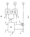
- Wie Fig. 2 zeigt, hat die Master-Kontrolleinheit 10 einen Logikbaustein 20, der an einen Leistungsteil 21 des Fahrzeuges angeschlossen ist. Mit ihm wird die Strom/Spannungsversorgung des Logikbausteins 20 sichergestellt. Der Logikbaustein 20 erhält außerdem ein Signal über die Leitung 11, die an den Lichtschalter des Fahrzeuges angeschlossen ist. Außerdem wird dem Logikbaustein über eine Leitung 13 ein ΔEC-Signal eines ΔEC-Schaltkreises im EC-Spiegel 14 zugeführt (Fig. 1). Die Bildung des ΔEC-Signals wird anhand von Fig. 3 noch erläutert werden. Außerdem erhält der Logikbaustein 20 über eine weitere Leitung 22 das Signal vom Schalter der Nebelschlußleuchte 7.
- Der Logikbaustein 20 steuert über eine Leitung 23 einen Leistungsschalter 24, mit dem die Nebelschlußleuchte 7 automatisch ein- und ausgeschaltet werden kann. Der Leistungsschalter 24 kann durch ein Relais, durch elektronische Bauteile und dergleichen gebildet sein. Das über die Leitung 22 kommende Signal wird im Logikbaustein 20 ausgewertet. Er sendet über die Leitung 23 ein entsprechendes Signal an den Leistungsschalter. Ist die Nebelschlußleuchte 7 eingeschaltet und nähert sich von hinten ein Fahrzeug, dann fällt, wie zuvor beschrieben, das vom nachfolgenden Fahrzeug ausgesandte Licht auf den EC-Spiegel 14. Seine Sensorik erfaßt dieses auffallende Licht, wertet es aus und sendet über die Leitung 13 ein entsprechendes Signal an den Logikbaustein 20 der Master-Kontrolleinheit 10. Der Logikbaustein 20 betätigt den Leistungsschalter 24 über die Leitung 23 so, daß die Nebelschlußleuchte 7 abgeschaltet wird. Sobald auf den EC-Spiegel 14 kein Licht mehr auftrifft bzw. die auftreffende Lichtstärke ein bestimmtes Maß unterschritten hat, wird dies von der Sensorik des EC-Spiegels 14 erfaßt. Er sendet über die Leitung 13 wiederum ein entsprechendes Signal an den Logikbaustein 20, in dem dieses Signal ausgewertet wird. Der Logikbaustein betätigt den Leistungsschalter 24, so daß die Nebelschlußleuchte 7 automatisch wieder eingeschaltet wird.
- Mit dem Logikbaustein 20 wird außerdem das Bremslicht 3 und das Blinklicht 4 in zwei unterschiedlichen Lichtstärken betätigt. Fährt das Fahrzeug bei Tag und ist der Lichtschalter des Fahrzeuges nicht eingeschaltet, dann werden das Bremslicht 3 und das Blinklicht 4 mit einer stärkeren Lichtstärke betrieben (Tagstellung). Fährt das Fahrzeug bei Dunkelheit und ist der Lichtschalter des Fahrzeuges eingeschaltet, reicht eine geringere Leuchtstärke für das Bremslicht 3 und das Blinklicht 4 aus. Über die Leitung 11 wird dem Logikbaustein 20 in Abhängigkeit von der Stellung des Lichtschalters ein entsprechendes Signal zugeführt. Dementsprechend werden die empfangenen Signale vom Logikbaustein 20 ausgewertet. An einem Ausgang 25 steht dann in Abhängigkeit von der Stellung des Lichtschalters ein Low- oder ein High-Signal an. Ein Low-Signal wird beispielsweise dann erzeugt, wenn der Lichtschalter des Fahrzeuges eingeschaltet ist. In diesem Falle reicht es aus, das Bremslicht 3 und das Blinklicht 4 mit einer geringeren Lichtstärke zu betreiben. Ist der Lichtschalter hingegen nicht eingeschaltet, dann steht am Ausgang 25 des Logikbausteins 20 beispielsweise ein High-Signal an, wodurch das Bremslicht 3 und das Blinklicht 4 mit höherer Lichtstärke betrieben werden. Somit ist eine automatische Anpassung der Lichtstärke an Tag- und an Nachtfahrt möglich. Wie Fig. 2 zeigt, kann für das Blinklicht 4 eine Glühlampe verwendet werden, während für das Bremslicht 3 als Leuchtmittel LEDs eingesetzt werden können. Selbstverständlich ist es auch möglich, für das Bremslicht 3 mindestens eine Glühlampe einzusetzen oder für das Blinklicht alternativ LEDs zu verwenden oder gar eine Minderung von beiden anzuwenden.
- Die Höhe des Low- und High-Signales kann vorteilhaft fahrzeugspezifisch eingestellt werden. Entsprechende Stellsignale 26 und 27 sind zu diesem Zweck vorgesehen.
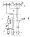
- Die beschriebene Regelung der einzelnen Leuchtmittelfunktionen erfolgt vorteilhaft über eine Pulsweitenmodulation (Fig. 4) oder über eine verteilte Stromregelung oder über eine Summenstromregelung. Fig. 4 zeigt die Zweipegelschaltung der Master-Kontrolleinheit 10, mit der die Leuchtmittel der beiden Heckleuchten 1 und 2 in der beschriebenen Weise betätigt werden. Das Bremslicht 3 der beiden Heckleuchten 1, 2 wird vorzugsweise durch LEDs gebildet, während das Schlußlicht 6, das Blinklicht 4, der Rückstrahler 5 und die Nebelschlußleuchte 7 der beiden Heckleuchten 1, 2 durch Glühlampen gebildet sind. Die beiden Heckleuchten 1, 2 werden durch einen Schalter 28 als Lichtschalter betätigt, der im dargestellten Ausführungsbeispiel ein Drehschalter ist. Für das Bremslicht 3 und den Blinker 4 ist jeweils ein in Pulsweitenmodulation arbeitender Dimmer 29 und 30 vorgesehen, der in der Leitungsverbindung von Schaltern 32, 33 zu den Leuchtmitteln 3 und 4 liegt. Für das Blinklicht 4 ist die Master-Kontrolleinheit mit einem Blinkgeber 31 versehen.
- Parallel zu den Dimmern 29, 30 liegt jeweils ein Schalter S1a, S1b. Sind diese Schalter geschlossen, wird der jeweilige Dimmer 29, 30 überbrückt. An den Schalter 28 ist über einen Schalter EC1 die Nebelschlußleuchte 7 angeschlossen. Ist der Schalter EC1 geöffnet, ist die Nebelschlußleuchte 7 abgeschaltet. In der Leitungsverbindung vor der Bordspannungsversorgung zum Dimmer 29 liegt ein Schalter 32, der mit der Bremse des Fahrzeuges gekoppelt ist. Wird die Bremse betätigt, schließt der Schalter 32, so daß das Bremslicht 3 aufleuchten kann.
- Fährt das Fahrzeug bei Tag, ist der Lichtschalter 28 ausgeschaltet. In diesem Falle sind die Schalter S1a, S2a geschlossen, so daß die Dimmer 29, 30 überbrückt sind. Wird daher die Bremse oder der Blinker des Fahrzeuges betätigt, leuchten das Bremslicht 3 und das Blinklicht 4 mit hoher Lichtstärke. Fährt das Fahrzeug bei Nacht, wird mit dem Schalter 28 die Kraftfahrzeugbeleuchtung eingeschaltet.
Dies hat zur Folge, daß die beiden Schalter S1a, S1b geöffnet werden. Über die Dimmer 29, 30 werden dann das Bremslicht 3 und das Blinklicht 4 mit einer geringeren Spannung bzw. einem geringeren Strom versorgt, so daß sie in einer geringeren Lichtstärke aufleuchten. Die Regelung der einzelnen Lampenfunktionen erfolgt hierbei in den Dimmern 29, 30 mittels einer Pulsweitenmodulation. - Die Schalter EC1 und EC2 werden von der Sensorik des EC-Spiegels 14 geschaltet. Der Schalter EC1 liegt zwischen dem Schalter 28 und der Nebelschlußleuchte 7 in Reihe. Ist die Nebelschlußleuchte 7 über den Schalter 28 eingeschaltet, dann wird die Nebelschlußleuchte 7 in der beschriebenen Weise automatisch ausgeschaltet, wenn sich dem Fahrzeug von hinten ein beleuchtetes Fahrzeug nähert. Das von ihm ausgesandte Licht gelangt auf den EC-Spiegel 14, der die empfangenen Lichtsignale des nachfolgenden Fahrzeuges in der beschriebenen Weise auswertet. Durch ein entsprechendes Schaltsignal wird der Schalter EC1 geöffnet und damit die Nebelschlußleuchte 7 ausgeschaltet.
- Fig. 3 zeigt einen EC-Adapter 51, der Bestandteil der Sensorik des EC-Spiegels 14 ist und mit dem durch Differentiation die Nebelschlußleuchte 7 automatisch abgeschaltet wird. Der Schaltkreis des EC-Adapters 51 ist an die Strom/Spannungsversorgung des Fahrzeuges angeschlossen. An den Anschlüssen 34, 35 liegt beispielsweise eine Spannung von 13,5 V an. Die Anschlüsse 36, 37 liegen auf Masse. Über einen Anschluß 38 erhält der EC-Adapter 51 ein Signal des EC-Spiegels 14 bzw. von dessen Sensorik. Dieses EC-Signal wird einem Eingang 39 eines Vergleichers 40 zugeführt. Er vergleicht dieses Signal mit einem an seinem weiteren Eingang 41 anstehenden Vergleichssignal. Am Ausgang 42 des Vergleichers 40 steht das Differenzsignal an, das einer Kippstufe 43 zugeführt wird. Ihm ist ein Transistor 44 nachgeschaltet, mit dem ein Relais 45 zum Betätigen der Schalter EC1 und EC2 betätigt werden kann. Der Eingang 41 des Vergleichers 40 ist Teil einer Vergleicherschaltung 46, welche in Reihe geschaltete Widerstände 47 und 48 bzw. 49 und 50 aufweist. Die Widerstände 47, 48 sind parallel zu den Widerständen 49, 50 geschaltet. Die Widerstandswerte werden so gewählt, daß am Eingang 41 zwei unterschiedliche Spannungswerte anliegen, die im Ausführungsbeispiel beispielsweise 0,3 V und 0,7 V betragen. Die Kippstufe 43 ist so ausgelegt, daß sie ab einer Spannung von im Ausführungsbeispiel 0,7 V ein Signal abgibt. In einem Spannungsbereich zwischen 0,3 V und 0,7 V hält die Kippstufe 43 das Signal, während sie bei einem Spannungswert von kleiner als 0,3 V kein Signal abgibt. Dementsprechend wird durch den nachgeschalteten Transistor 44 das Relais 45 zum Betätigen der Schalter EC1 bzw. EC2 geschaltet. Die angegebenen Spannungswerte können selbstverständlich auch andere Werte haben. Diese beiden Spannungswerte kennzeichnen die beiden unterschiedlichen Schaltschwellen, bei denen das Bremslicht 3 und das Blinklicht 4 zwischen Hell- und Dunkelbetrieb umgeschaltet werden, so daß sie in zwei unterschiedlichen Lichtstärken leuchten. Über diese Differentiation werden das Bremslicht 3 und das Blinklicht 4 mit der erforderlichen Spannung versorgt, so daß sie je nach Umgebungsverhältnissen in unterschiedlichen Stärken leuchten. Bei Tagesfahrt leuchten das Bremslicht 3 und das Blinklicht 4 mit höherer Lichtstärke als bei Nachtfahrt.
- Der Schalter EC2 tritt beispielsweise dann in Funktion, wenn das Fahrzeug in einen Tunnel fährt und von hinten durch ein nachfolgendes Fahrzeug beleuchtet wird. In diesem Fall erhält der EC-Spiegel von hinten mehr Licht als von vorn, so daß über den Anschluß 38 ein entsprechendes EC-Signal im Eingang 39 des Vergleichers 40 zugeführt wird. Der EC-Adapter 51 schließt den Schalter EC2, wodurch das nachgeschaltete Relais RE1a, b (Fig. 4) angezogen und die Schalter S1a, S1b geöffnet werden. Dadurch werden die Dimmer 29, 30 in den Stromweg zum Bremslicht 3 und zum Blinklicht 4 geschaltet, so daß sichergestellt ist, daß sie mit einer verringerten Leuchtstärke strahlen. Dadurch wird eine Blendung nachfolgender Fahrzeuge durch zu intensiv leuchtende Brems- und Blinklichter zuverlässig verhindert. Sobald das Tunnel verlassen wird, wird dies von der Sensorik des EC-Spiegels 14 aufgrund eines intensiven Lichteinfalles von vorn bemerkt. Am Eingang 39 des Vergleichers 40 steht ein dementsprechendes Signal an, das im EC-Adapter 51 verarbeitet und zum Öffnen des Schalters EC2 herangezogen wird. Dadurch fällt das Relais RE1a, 1b ab, wodurch die Schalter S1a, S1b wieder geschlossen werden. Die beiden Dimmer 29, 30 werden somit wieder überbrückt, so daß das Bremslicht 3 und das Blinklicht 4 wieder mit einer höheren Lichtstärke aufleuchten.
- Fig. 5 zeigt beispielhaft den Verlauf der EC-Signalspannung in Abhängigkeit von der Zeit t. Die beiden Spannungspegel von 0,3 V und 0,7 V kennzeichnen das Low- und das High-Signal. Solange die EC-Signalspannung einen Spannungswert unterhalb von 0,3 V hat, ist die Nebelschlußleuchte 7 eingeschaltet. Dieser Fall tritt, wie schon dargelegt, im Normalbetrieb auf, wenn kein Fahrzeug nachfolgt. Sobald sich jedoch von hinten ein Fahrzeug nähert und dessen Scheinwerferlicht auf den EC-Spiegel 14 des vorausfahrenden Fahrzeuges auftritt, nimmt die EC-Signalspannung zu. Sobald sie einen Wert von mehr als 0,7 V aufweist, wird in der beschriebenen Weise die Nebelschlußleuchte 7 automatisch abgeschaltet, so daß das nachfolgende Fahrzeug durch die Nebelschlußleuchte nicht geblendet wird. Die Nebelschlußleuchte 7 bleibt so lange ausgeschaltet, bis der Wert der EC-Signalspannung wieder unter 0,3 V absinkt. Erst dann wird in der beschriebenen Weise die Nebelschlußleuchte 7 automatisch wieder eingeschaltet.
- Die Master- und die Slave-Kontrolleinheit 10, 8 können mit sogenannten Fail-Safe-Schaltkreisen versehen sein. Sollte eine Störung in der Schaltung oder gar ein Ausfall auftreten, wird die Schaltung auf den Low-Pegel geschaltet, so daß das Bremslicht 3 und das Rücklicht 4 mit verringerter Leuchtstärke aufleuchten. Dadurch ist auf jeden Fall gewährleistet, daß die Fahrer nachfolgender Fahrzeuge durch diese Lichter nicht geblendet werden. Über einen weiteren Sensor im EC-Spiegel 14 ist eine Automatisierung des Lichtschalters (Tag/Nacht) zuverlässig gewährleistet. Anstelle der beschriebenen Pulsweitenmodulation kann die Regelung der einzelnen Lampenfunktionen auch über eine Widerstandsschaltung, über einen Summenstromregler oder insbesondere auch über verteilte Stromregler erfolgen.
Claims (14)
- Leuchte eines Fahrzeuges, mit wenigstens einem Leuchtmittel (3, 4, 7), das an eine Schaltung (10) angeschlossen und in Abhängigkeit von den äußeren Lichtverhältnissen in seiner Lichtstärke einstellbar ist, wobei die Schaltung wenigstens einen Dimmer (29, 30) aufweist, mit dem die Lichtstärke des Leuchtmittels (3, 4, 7) verringerbar ist, und wobei die Schaltung (10) eine Master-Kontrolleinheit (10) ist,
dadurch gekennzeichnet, daß der Master-Kontrolleinheit (10) eine Slave-Kontrolleinheit (8) nachgeschaltet ist, mit der wenigstens ein Leuchtmittel (3, 4) einer zweiten Leuchte (1, 2) ansteuerbar ist. - Leuchte nach Anspruch 1,
dadurch gekennzeichnet, daß die Lichtstärke des Leuchtmittels (3, 4, 7) in Abhängigkeit von der Stellung eines Lichtschalters (28) des Fahrzeuges einstellbar ist. - Leuchte nach Anspruch 1 oder 2,
dadurch gekennzeichnet, daß der Dimmer (29, 30) zur Erhöhung der Lichtstärke des Leuchtmittels (3, 4) überbrückbar ist. - Leuchte nach Anspruch 3,
dadurch gekennzeichnet, daß zum Dimmer (29, 30) ein Schalter (S1a, S1b) parallel geschaltet ist, der in der Leitungsverbindung von einem weiteren Schalter (32, 33) zum Leuchtmittel (3, 4) liegt. - Leuchte nach einem der Ansprüche 1 bis 4,
dadurch gekennzeichnet, daß das Leuchtmittel ein Bremslicht (3) ist. - Leuchte nach einem der Ansprüche 1 bis 4,
dadurch gekennzeichnet, daß das Leuchtmittel ein Blinklicht (4) ist. - Leuchte nach Anspruch 5 oder 6,
dadurch gekennzeichnet, daß das Bremslicht (3) und/oder das Blinklicht (4) durch LEDs gebildet ist. - Leuchte nach einem der Ansprüche 1 bis 7,
dadurch gekennzeichnet, daß das Leuchtmittel (3, 4, 7) mit einer Sensorik eines elektrochromen Innenspiegels (14) des Fahrzeuges verbunden ist, die die Lichtstärke des Leuchtmittels (3, 4, 7) bei Herannahen eines nachfolgenden Fahrzeuges zumindest verringert. - Leuchte nach Anspruch 8,
dadurch gekennzeichnet, daß das Leuchtmittel (7) ein Nebelschlußlicht ist. - Leuchte nach Anspruch 9,
dadurch gekennzeichnet, daß die Sensorik des elektrochromen Innenspiegels (14) die Lichtstärke des Nebenschlußlichtes (7) bei Herannahen des nachfolgenden Fahrzeuges abschaltet. - Leuchte nach einem der Ansprüche 8 bis 10,
dadurch gekennzeichnet, daß die Sensorik des EC-Spiegels (14) an eine Vergleicherschaltung (46) angeschlossen ist, die den vom EC-Spiegel (14) kommenden Istwert mit einem Referenzwert vergleicht - Leuchte nach Anspruch 11,
dadurch gekennzeichnet, daß die Vergleicherschaltung (46) einen Vergleicher (14) aufweist, dessen Ausgangssignal zur Steuerung des Nebelschlußlichtes (7) herangezogen wird. - Leuchte nach Anspruch 12,
dadurch gekennzeichnet, daß dem Vergleicher (40) eine Kippstufe (43) nachgeschaltet ist, die in Abhängigkeit vom Ausgangssignal des Vergleichers (40) das Nebelschlußlicht (7) ein- oder ausschaltet - Leuchte nach Anspruch 13,
dadurch gekennzeichnet, daß mit der Kippstufe (43) wenigstens ein Schalter (EC1) zum Ein- oder Ausschalten des Nebelschlußlichtes (7) betätigbar ist.
Applications Claiming Priority (2)
| Application Number | Priority Date | Filing Date | Title |
|---|---|---|---|
| DE19714849A DE19714849A1 (de) | 1997-04-10 | 1997-04-10 | Leuchte, vorzugsweise Heckleuchte, eines Fahrzeuges, vorzugsweise eines Kraftfahrzeuges |
| DE19714849 | 1997-04-10 |
Publications (3)
| Publication Number | Publication Date |
|---|---|
| EP0870644A2 EP0870644A2 (de) | 1998-10-14 |
| EP0870644A3 EP0870644A3 (de) | 2000-03-08 |
| EP0870644B1 true EP0870644B1 (de) | 2007-01-03 |
Family
ID=7826038
Family Applications (1)
| Application Number | Title | Priority Date | Filing Date |
|---|---|---|---|
| EP98103236A Expired - Lifetime EP0870644B1 (de) | 1997-04-10 | 1998-02-25 | Fahrzeugleuchte |
Country Status (4)
| Country | Link |
|---|---|
| US (1) | US6016035A (de) |
| EP (1) | EP0870644B1 (de) |
| DE (2) | DE19714849A1 (de) |
| ES (1) | ES2276437T3 (de) |
Families Citing this family (54)
| Publication number | Priority date | Publication date | Assignee | Title |
|---|---|---|---|---|
| US5910854A (en) | 1993-02-26 | 1999-06-08 | Donnelly Corporation | Electrochromic polymeric solid films, manufacturing electrochromic devices using such solid films, and processes for making such solid films and devices |
| US5668663A (en) | 1994-05-05 | 1997-09-16 | Donnelly Corporation | Electrochromic mirrors and devices |
| US6891563B2 (en) | 1996-05-22 | 2005-05-10 | Donnelly Corporation | Vehicular vision system |
| US6587573B1 (en) * | 2000-03-20 | 2003-07-01 | Gentex Corporation | System for controlling exterior vehicle lights |
| US6326613B1 (en) | 1998-01-07 | 2001-12-04 | Donnelly Corporation | Vehicle interior mirror assembly adapted for containing a rain sensor |
| US8294975B2 (en) | 1997-08-25 | 2012-10-23 | Donnelly Corporation | Automotive rearview mirror assembly |
| US6124886A (en) | 1997-08-25 | 2000-09-26 | Donnelly Corporation | Modular rearview mirror assembly |
| US6172613B1 (en) * | 1998-02-18 | 2001-01-09 | Donnelly Corporation | Rearview mirror assembly incorporating vehicle information display |
| US6445287B1 (en) | 2000-02-28 | 2002-09-03 | Donnelly Corporation | Tire inflation assistance monitoring system |
| US8288711B2 (en) | 1998-01-07 | 2012-10-16 | Donnelly Corporation | Interior rearview mirror system with forwardly-viewing camera and a control |
| US6329925B1 (en) * | 1999-11-24 | 2001-12-11 | Donnelly Corporation | Rearview mirror assembly with added feature modular display |
| US6693517B2 (en) | 2000-04-21 | 2004-02-17 | Donnelly Corporation | Vehicle mirror assembly communicating wirelessly with vehicle accessories and occupants |
| US6477464B2 (en) | 2000-03-09 | 2002-11-05 | Donnelly Corporation | Complete mirror-based global-positioning system (GPS) navigation solution |
| US6158882A (en) * | 1998-06-30 | 2000-12-12 | Emteq, Inc. | LED semiconductor lighting system |
| DE19901413C2 (de) * | 1999-01-16 | 2002-12-05 | Helmut Haf | Elektronik eines Fahrzeuges, vorzugsweise eines Kraftfahrzeuges |
| DE19945775B4 (de) * | 1999-09-24 | 2005-05-25 | Audi Ag | Leuchtenanordnung als Heckleuchte für ein Kraftfahrzeug |
| US7049761B2 (en) | 2000-02-11 | 2006-05-23 | Altair Engineering, Inc. | Light tube and power supply circuit |
| WO2007053710A2 (en) | 2005-11-01 | 2007-05-10 | Donnelly Corporation | Interior rearview mirror with display |
| US7167796B2 (en) * | 2000-03-09 | 2007-01-23 | Donnelly Corporation | Vehicle navigation system for use with a telematics system |
| EP1263626A2 (de) | 2000-03-02 | 2002-12-11 | Donnelly Corporation | Video-spiegelsystem mit zusatzmodul |
| US7370983B2 (en) | 2000-03-02 | 2008-05-13 | Donnelly Corporation | Interior mirror assembly with display |
| US7255451B2 (en) | 2002-09-20 | 2007-08-14 | Donnelly Corporation | Electro-optic mirror cell |
| ATE363413T1 (de) * | 2001-01-23 | 2007-06-15 | Donnelly Corp | Verbessertes fahrzeugbeleuchtungssystem |
| US7581859B2 (en) | 2005-09-14 | 2009-09-01 | Donnelly Corp. | Display device for exterior rearview mirror |
| DE10154983A1 (de) * | 2001-11-08 | 2003-05-22 | Opel Adam Ag | Blinkanlage für ein Kraftfahrzeug |
| US6641294B2 (en) | 2002-03-22 | 2003-11-04 | Emteq, Inc. | Vehicle lighting assembly with stepped dimming |
| US6918674B2 (en) | 2002-05-03 | 2005-07-19 | Donnelly Corporation | Vehicle rearview mirror system |
| US7329013B2 (en) | 2002-06-06 | 2008-02-12 | Donnelly Corporation | Interior rearview mirror system with compass |
| WO2003105099A1 (en) * | 2002-06-06 | 2003-12-18 | Donnelly Corporation | Interior rearview mirror system with compass |
| US7310177B2 (en) | 2002-09-20 | 2007-12-18 | Donnelly Corporation | Electro-optic reflective element assembly |
| AU2003278863A1 (en) | 2002-09-20 | 2004-04-08 | Donnelly Corporation | Mirror reflective element assembly |
| WO2004103772A2 (en) | 2003-05-19 | 2004-12-02 | Donnelly Corporation | Mirror assembly for vehicle |
| US7446924B2 (en) | 2003-10-02 | 2008-11-04 | Donnelly Corporation | Mirror reflective element assembly including electronic component |
| US7308341B2 (en) | 2003-10-14 | 2007-12-11 | Donnelly Corporation | Vehicle communication system |
| DE102004002334B4 (de) * | 2004-01-16 | 2006-01-26 | Adam Opel Ag | Steuerschaltung für die Beleuchtungsanlage eines Kraftfahrzeuges |
| ES2245870B1 (es) * | 2004-02-13 | 2007-07-16 | Marcelino Hervas De La Torre | Dispositivo regulador luz antiniebla trasera. |
| DE102004022555B4 (de) * | 2004-05-07 | 2006-04-06 | Siemens Ag | Vorrichtung und Verfahren zum Synchronisieren einer Blinkerfrequenz mit einer Zentralblinkfrequenz |
| ATE517368T1 (de) | 2005-05-16 | 2011-08-15 | Donnelly Corp | Fahrzeugspiegelanordnung mit zeichen am reflektierenden teil |
| DE102006008276B4 (de) * | 2006-02-22 | 2018-02-15 | Continental Automotive Gmbh | Verfahren und Steuergerät zum Steuern einer Leistung einer Leuchte |
| ITBO20070181A1 (it) * | 2007-03-15 | 2008-09-16 | Luca Gurioli | Metodo e dispositivo per il controllo dei fari retronebbia dei veicoli |
| DE102007017170A1 (de) * | 2007-04-12 | 2008-10-16 | GM Global Technology Operations, Inc., Detroit | Selbstabblendender Spiegel in einem Kraftfahrzeug |
| DE102008005314A1 (de) * | 2008-01-21 | 2009-07-23 | Robert Bosch Gmbh | Verfahren und Vorrichtung zum Erfassen eines vorbeifahrenden Fahrzeuges bei Dunkelheit |
| US8154418B2 (en) | 2008-03-31 | 2012-04-10 | Magna Mirrors Of America, Inc. | Interior rearview mirror system |
| US9487144B2 (en) | 2008-10-16 | 2016-11-08 | Magna Mirrors Of America, Inc. | Interior mirror assembly with display |
| US9315146B2 (en) * | 2010-04-13 | 2016-04-19 | Kory Patrick Purks | Vehicle turn signalling apparatuses with laser devices, light projection circuits, and related electromechanical actuators |
| DE102010044800A1 (de) * | 2010-09-09 | 2012-03-15 | Bpw Bergische Achsen Kg | Fahrzeugbeleuchtungssystem mit einer Ausweichschaltung |
| ITPV20110004A1 (it) * | 2011-02-08 | 2012-08-09 | Luigi Buonanno | Retrofaro antinebbia di sicurezza per autoveicolo |
| DE102012020272A1 (de) * | 2012-10-17 | 2014-04-17 | Claudia Goschau | Steuergerät/Schaltkreis zur Dimmung der Bremslichtfunktion an Kraftfahrzeugen |
| KR101703147B1 (ko) * | 2013-07-08 | 2017-02-06 | 한국전자통신연구원 | 밝기 조절 및 가시광 무선통신이 가능한 차량 후미등 제어 장치 및 방법 |
| DE102016205683A1 (de) * | 2016-04-06 | 2017-10-12 | Bayerische Motoren Werke Aktiengesellschaft | Fahrzeugscheinwerfersystem |
| US10000157B2 (en) * | 2016-04-29 | 2018-06-19 | Faraday&Future Inc. | Controlling dimming of mirrors or displays using dual-function lighting |
| FR3056679B1 (fr) * | 2016-09-27 | 2020-09-04 | Valeo Vision | Dispositif avec modules lumineux maitre et esclave |
| DE102016224147B4 (de) | 2016-12-05 | 2022-04-28 | Audi Ag | System zur distanz- und geschwindigkeitssensitiven Steuerung der Helligkeit eines von einer Heckleuchte eines Ego-Fahrzeugs abgestrahlten Lichts |
| FR3106395A1 (fr) * | 2020-01-21 | 2021-07-23 | Psa Automobiles Sa | Méthodes et systèmes de commande des feux de brouillard arrière |
Family Cites Families (11)
| Publication number | Priority date | Publication date | Assignee | Title |
|---|---|---|---|---|
| US2827594A (en) * | 1954-09-02 | 1958-03-18 | Rabinow Jacob | Color discriminating headlight dimmer |
| US2944188A (en) * | 1958-04-10 | 1960-07-05 | Gen Motors Corp | Automatic light controlled headlamp means |
| US4211955A (en) * | 1978-03-02 | 1980-07-08 | Ray Stephen W | Solid state lamp |
| DE3040714A1 (de) * | 1980-10-29 | 1982-05-27 | Rolf Dipl.-Ing. 5600 Wuppertal Rychzynski | Helligkeitsgeregeltes bremslicht von kraftfahrzeugen |
| DE3416164A1 (de) * | 1984-05-02 | 1985-11-21 | Christian 5630 Remscheid Hegermann | Einrichtung zur ueberwachung des aussenlichtes ob fahrzeuglicht benoetigt wird, mit gleichzeitiger kontrolle des eingeschalteten fahrzeuglichtes auf funktion und lichtintensitaet |
| JPH0416447Y2 (de) * | 1985-07-22 | 1992-04-13 | ||
| US4665321A (en) * | 1985-08-14 | 1987-05-12 | Kwangling Chang | Automatic control system for automobile lights |
| US4841198A (en) * | 1987-10-19 | 1989-06-20 | Nartron Corporation | Head lamp control method and apparatus, with PWM output regulation |
| JP2957079B2 (ja) * | 1994-03-03 | 1999-10-04 | 矢崎総業株式会社 | 照明調光器 |
| DE69528123T2 (de) * | 1994-07-19 | 2003-06-05 | Donnelly Corp | Automatisches Rückspiegelsystem mit selbsttätiger Scheinwerfer-Betätigung |
| DE19615808A1 (de) * | 1996-04-20 | 1997-10-23 | Reitter & Schefenacker Gmbh | Rückleuchte eines Fahrzeuges, vorzugsweise eines Kraftfahrzeuges |
-
1997
- 1997-04-10 DE DE19714849A patent/DE19714849A1/de not_active Ceased
-
1998
- 1998-02-25 EP EP98103236A patent/EP0870644B1/de not_active Expired - Lifetime
- 1998-02-25 ES ES98103236T patent/ES2276437T3/es not_active Expired - Lifetime
- 1998-02-25 DE DE59813861T patent/DE59813861D1/de not_active Expired - Lifetime
- 1998-04-10 US US09/059,059 patent/US6016035A/en not_active Expired - Lifetime
Also Published As
| Publication number | Publication date |
|---|---|
| US6016035A (en) | 2000-01-18 |
| DE19714849A1 (de) | 1998-10-15 |
| EP0870644A3 (de) | 2000-03-08 |
| ES2276437T3 (es) | 2007-06-16 |
| DE59813861D1 (de) | 2007-02-15 |
| EP0870644A2 (de) | 1998-10-14 |
Similar Documents
| Publication | Publication Date | Title |
|---|---|---|
| EP0870644B1 (de) | Fahrzeugleuchte | |
| EP0802081B1 (de) | Rückleuchte eines Fahrzeuges, vorzugsweise eines Kraftfahrzeuges | |
| DE102004045435A1 (de) | Überwachung der Funktion von Glühlampen oder LED-Leuchten in Kraftfahrzeugen | |
| EP1950089B1 (de) | Fahrzeugbeleuchtung | |
| EP2067660A2 (de) | Verfahren zum Verringern der Helligkeitsabgabe von Leuchtmitteln und Vorrichtung zum Vermindern der Helligkeit von Leuchtmitteln bei Fahrzeugen | |
| DE102018200334A1 (de) | Fahrtrichtungsanzeiger, insbesondere mit Wischeffekt und Warnblinkfunktion | |
| EP1818214B1 (de) | Leuchte, insbesondere Heckleuchte eines Fahrzeuges, vorzugsweise eines Kraftfahrzeuges | |
| DE19953447A1 (de) | Steuereinrichtung für Bremsleuchten | |
| DE4035956A1 (de) | Schaltungseinrichtung fuer eine kraftfahrzeugleuchte | |
| DE3724916A1 (de) | Kraftfahrzeug fuer anhaengerbetrieb mit heckleuchten-ueberwachung | |
| DE102008031078B4 (de) | Fahrzeugleuchte | |
| DE102011051152A1 (de) | Verfahren zum Betrieb einer Leuchte sowie Leuchte für ein Fahrzeug | |
| EP2722227A1 (de) | Kraftfahrzeug-Lichtanlage und entsprechendes Betriebsverfahren | |
| DE3436391A1 (de) | Verfahren zur betaetigung der frontseitigen beleuchtungsanlage eines kraftfahrzeuges und schaltungsanordnung zur durchfuehrung des verfahrens | |
| DE102011006423A1 (de) | Lichtsteuereinrichtung für ein Kraftfahrzeug und Verfahren zum Steuern der Funktion eines Blinklichts und eines Tagfahrlichts | |
| DE1530678A1 (de) | Beleuchtungs- und Blinkanlage fuer Kraftfahrzeuge | |
| DE4408959C1 (de) | Schaltung für eine Anlage mit einem intermittierend betreibbaren Element, insbesondere eine Kraftfahrzeug-Warnblinkanlage | |
| DE1954025A1 (de) | Vorrichtung zur AEnderung der Intensitaet von Signallampen,insbesondere Fahrzeuglampen | |
| DE102013222628A1 (de) | Verfahren und Vorrichtung zum Erfassen einer Fehleinstellung einer lichttechnischen Einrichtung eines Fahrzeugs | |
| EP3363685A1 (de) | Fahrzeugleuchte und verfahren zu deren betrieb | |
| EP1731362A2 (de) | Beleuchtungseinrichtung für ein Personenbeförderungsmittel | |
| EP4051955B1 (de) | Verfahren zum betrieb einer heckleuchte eines kraftfahrzeugs und kraftfahrzeug | |
| EP3399840A1 (de) | Steuern von wenigstens einem leuchtmittel eines fahrzeugscheinwerfers abhängig von einer an einem fahrzeugscheinwerferanschluss eines fahrzeugs bereitstellbaren elektrischen grösse | |
| DE202010016339U1 (de) | Schaltungsanordnung | |
| DE102006008276B4 (de) | Verfahren und Steuergerät zum Steuern einer Leistung einer Leuchte |
Legal Events
| Date | Code | Title | Description |
|---|---|---|---|
| PUAI | Public reference made under article 153(3) epc to a published international application that has entered the european phase |
Free format text: ORIGINAL CODE: 0009012 |
|
| AK | Designated contracting states |
Kind code of ref document: A2 Designated state(s): BE DE ES FR GB IT LU NL SE |
|
| AX | Request for extension of the european patent |
Free format text: AL;LT;LV;MK;RO;SI |
|
| PUAL | Search report despatched |
Free format text: ORIGINAL CODE: 0009013 |
|
| AK | Designated contracting states |
Kind code of ref document: A3 Designated state(s): AT BE CH DE DK ES FI FR GB GR IE IT LI LU MC NL PT SE |
|
| AX | Request for extension of the european patent |
Free format text: AL;LT;LV;MK;RO;SI |
|
| 17P | Request for examination filed |
Effective date: 20000711 |
|
| AKX | Designation fees paid |
Free format text: BE DE ES FR GB IT LU NL SE |
|
| 17Q | First examination report despatched |
Effective date: 20031103 |
|
| GRAP | Despatch of communication of intention to grant a patent |
Free format text: ORIGINAL CODE: EPIDOSNIGR1 |
|
| GRAS | Grant fee paid |
Free format text: ORIGINAL CODE: EPIDOSNIGR3 |
|
| RAP1 | Party data changed (applicant data changed or rights of an application transferred) |
Owner name: SCHEFENACKER VISION SYSTEMS GERMANY GMBH |
|
| GRAA | (expected) grant |
Free format text: ORIGINAL CODE: 0009210 |
|
| AK | Designated contracting states |
Kind code of ref document: B1 Designated state(s): BE DE ES FR GB IT LU NL SE |
|
| PG25 | Lapsed in a contracting state [announced via postgrant information from national office to epo] |
Ref country code: NL Free format text: LAPSE BECAUSE OF FAILURE TO SUBMIT A TRANSLATION OF THE DESCRIPTION OR TO PAY THE FEE WITHIN THE PRESCRIBED TIME-LIMIT Effective date: 20070103 |
|
| REG | Reference to a national code |
Ref country code: GB Ref legal event code: FG4D Free format text: NOT ENGLISH |
|
| REF | Corresponds to: |
Ref document number: 59813861 Country of ref document: DE Date of ref document: 20070215 Kind code of ref document: P |
|
| PGFP | Annual fee paid to national office [announced via postgrant information from national office to epo] |
Ref country code: GB Payment date: 20070327 Year of fee payment: 10 |
|
| PG25 | Lapsed in a contracting state [announced via postgrant information from national office to epo] |
Ref country code: SE Free format text: LAPSE BECAUSE OF FAILURE TO SUBMIT A TRANSLATION OF THE DESCRIPTION OR TO PAY THE FEE WITHIN THE PRESCRIBED TIME-LIMIT Effective date: 20070403 |
|
| GBT | Gb: translation of ep patent filed (gb section 77(6)(a)/1977) |
Effective date: 20070329 |
|
| PGFP | Annual fee paid to national office [announced via postgrant information from national office to epo] |
Ref country code: ES Payment date: 20070425 Year of fee payment: 10 |
|
| REG | Reference to a national code |
Ref country code: ES Ref legal event code: FG2A Ref document number: 2276437 Country of ref document: ES Kind code of ref document: T3 |
|
| ET | Fr: translation filed | ||
| NLV1 | Nl: lapsed or annulled due to failure to fulfill the requirements of art. 29p and 29m of the patents act | ||
| PLBE | No opposition filed within time limit |
Free format text: ORIGINAL CODE: 0009261 |
|
| STAA | Information on the status of an ep patent application or granted ep patent |
Free format text: STATUS: NO OPPOSITION FILED WITHIN TIME LIMIT |
|
| 26N | No opposition filed |
Effective date: 20071005 |
|
| BERE | Be: lapsed |
Owner name: SCHEFENACKER VISION SYSTEMS GERMANY G.M.B.H. Effective date: 20070228 |
|
| PG25 | Lapsed in a contracting state [announced via postgrant information from national office to epo] |
Ref country code: BE Free format text: LAPSE BECAUSE OF NON-PAYMENT OF DUE FEES Effective date: 20070228 |
|
| GBPC | Gb: european patent ceased through non-payment of renewal fee |
Effective date: 20080225 |
|
| REG | Reference to a national code |
Ref country code: ES Ref legal event code: FD2A Effective date: 20080226 |
|
| PG25 | Lapsed in a contracting state [announced via postgrant information from national office to epo] |
Ref country code: GB Free format text: LAPSE BECAUSE OF NON-PAYMENT OF DUE FEES Effective date: 20080225 |
|
| PG25 | Lapsed in a contracting state [announced via postgrant information from national office to epo] |
Ref country code: ES Free format text: LAPSE BECAUSE OF NON-PAYMENT OF DUE FEES Effective date: 20080226 |
|
| PG25 | Lapsed in a contracting state [announced via postgrant information from national office to epo] |
Ref country code: LU Free format text: LAPSE BECAUSE OF NON-PAYMENT OF DUE FEES Effective date: 20070225 |
|
| PGFP | Annual fee paid to national office [announced via postgrant information from national office to epo] |
Ref country code: FR Payment date: 20120227 Year of fee payment: 15 |
|
| PGFP | Annual fee paid to national office [announced via postgrant information from national office to epo] |
Ref country code: DE Payment date: 20120221 Year of fee payment: 15 |
|
| PGFP | Annual fee paid to national office [announced via postgrant information from national office to epo] |
Ref country code: IT Payment date: 20120227 Year of fee payment: 15 |
|
| REG | Reference to a national code |
Ref country code: FR Ref legal event code: ST Effective date: 20131031 |
|
| REG | Reference to a national code |
Ref country code: DE Ref legal event code: R119 Ref document number: 59813861 Country of ref document: DE Effective date: 20130903 |
|
| PG25 | Lapsed in a contracting state [announced via postgrant information from national office to epo] |
Ref country code: IT Free format text: LAPSE BECAUSE OF NON-PAYMENT OF DUE FEES Effective date: 20130225 |
|
| PG25 | Lapsed in a contracting state [announced via postgrant information from national office to epo] |
Ref country code: DE Free format text: LAPSE BECAUSE OF NON-PAYMENT OF DUE FEES Effective date: 20130903 Ref country code: FR Free format text: LAPSE BECAUSE OF NON-PAYMENT OF DUE FEES Effective date: 20130228 |