EP0873009B1 - Multimedia system for transferring and receiving program number and methods therefor - Google Patents
Multimedia system for transferring and receiving program number and methods therefor Download PDFInfo
- Publication number
- EP0873009B1 EP0873009B1 EP19970307437 EP97307437A EP0873009B1 EP 0873009 B1 EP0873009 B1 EP 0873009B1 EP 19970307437 EP19970307437 EP 19970307437 EP 97307437 A EP97307437 A EP 97307437A EP 0873009 B1 EP0873009 B1 EP 0873009B1
- Authority
- EP
- European Patent Office
- Prior art keywords
- program
- recording
- digital interface
- program number
- transport stream
- Prior art date
- Legal status (The legal status is an assumption and is not a legal conclusion. Google has not performed a legal analysis and makes no representation as to the accuracy of the status listed.)
- Expired - Lifetime
Links
Images


Classifications
-
- H—ELECTRICITY
- H04—ELECTRIC COMMUNICATION TECHNIQUE
- H04L—TRANSMISSION OF DIGITAL INFORMATION, e.g. TELEGRAPHIC COMMUNICATION
- H04L12/00—Data switching networks
- H04L12/28—Data switching networks characterised by path configuration, e.g. LAN [Local Area Networks] or WAN [Wide Area Networks]
- H04L12/40—Bus networks
- H04L12/40052—High-speed IEEE 1394 serial bus
- H04L12/40058—Isochronous transmission
-
- H—ELECTRICITY
- H04—ELECTRIC COMMUNICATION TECHNIQUE
- H04N—PICTORIAL COMMUNICATION, e.g. TELEVISION
- H04N21/00—Selective content distribution, e.g. interactive television or video on demand [VOD]
- H04N21/40—Client devices specifically adapted for the reception of or interaction with content, e.g. set-top-box [STB]; Operations thereof
- H04N21/43—Processing of content or additional data, e.g. demultiplexing additional data from a digital video stream; Elementary client operations, e.g. monitoring of home network or synchronising decoder's clock; Client middleware
- H04N21/433—Content storage operation, e.g. storage operation in response to a pause request, caching operations
-
- H—ELECTRICITY
- H04—ELECTRIC COMMUNICATION TECHNIQUE
- H04L—TRANSMISSION OF DIGITAL INFORMATION, e.g. TELEGRAPHIC COMMUNICATION
- H04L12/00—Data switching networks
- H04L12/28—Data switching networks characterised by path configuration, e.g. LAN [Local Area Networks] or WAN [Wide Area Networks]
- H04L12/40—Bus networks
- H04L12/40052—High-speed IEEE 1394 serial bus
- H04L12/40071—Packet processing; Packet format
-
- H—ELECTRICITY
- H04—ELECTRIC COMMUNICATION TECHNIQUE
- H04L—TRANSMISSION OF DIGITAL INFORMATION, e.g. TELEGRAPHIC COMMUNICATION
- H04L12/00—Data switching networks
- H04L12/28—Data switching networks characterised by path configuration, e.g. LAN [Local Area Networks] or WAN [Wide Area Networks]
- H04L12/40—Bus networks
- H04L12/40052—High-speed IEEE 1394 serial bus
- H04L12/40117—Interconnection of audio or video/imaging devices
-
- H—ELECTRICITY
- H04—ELECTRIC COMMUNICATION TECHNIQUE
- H04N—PICTORIAL COMMUNICATION, e.g. TELEVISION
- H04N21/00—Selective content distribution, e.g. interactive television or video on demand [VOD]
- H04N21/40—Client devices specifically adapted for the reception of or interaction with content, e.g. set-top-box [STB]; Operations thereof
- H04N21/41—Structure of client; Structure of client peripherals
- H04N21/4104—Peripherals receiving signals from specially adapted client devices
- H04N21/4135—Peripherals receiving signals from specially adapted client devices external recorder
-
- H—ELECTRICITY
- H04—ELECTRIC COMMUNICATION TECHNIQUE
- H04N—PICTORIAL COMMUNICATION, e.g. TELEVISION
- H04N21/00—Selective content distribution, e.g. interactive television or video on demand [VOD]
- H04N21/40—Client devices specifically adapted for the reception of or interaction with content, e.g. set-top-box [STB]; Operations thereof
- H04N21/43—Processing of content or additional data, e.g. demultiplexing additional data from a digital video stream; Elementary client operations, e.g. monitoring of home network or synchronising decoder's clock; Client middleware
- H04N21/432—Content retrieval operation from a local storage medium, e.g. hard-disk
- H04N21/4325—Content retrieval operation from a local storage medium, e.g. hard-disk by playing back content from the storage medium
-
- H—ELECTRICITY
- H04—ELECTRIC COMMUNICATION TECHNIQUE
- H04N—PICTORIAL COMMUNICATION, e.g. TELEVISION
- H04N21/00—Selective content distribution, e.g. interactive television or video on demand [VOD]
- H04N21/40—Client devices specifically adapted for the reception of or interaction with content, e.g. set-top-box [STB]; Operations thereof
- H04N21/43—Processing of content or additional data, e.g. demultiplexing additional data from a digital video stream; Elementary client operations, e.g. monitoring of home network or synchronising decoder's clock; Client middleware
- H04N21/433—Content storage operation, e.g. storage operation in response to a pause request, caching operations
- H04N21/4334—Recording operations
-
- H—ELECTRICITY
- H04—ELECTRIC COMMUNICATION TECHNIQUE
- H04N—PICTORIAL COMMUNICATION, e.g. TELEVISION
- H04N21/00—Selective content distribution, e.g. interactive television or video on demand [VOD]
- H04N21/40—Client devices specifically adapted for the reception of or interaction with content, e.g. set-top-box [STB]; Operations thereof
- H04N21/43—Processing of content or additional data, e.g. demultiplexing additional data from a digital video stream; Elementary client operations, e.g. monitoring of home network or synchronising decoder's clock; Client middleware
- H04N21/434—Disassembling of a multiplex stream, e.g. demultiplexing audio and video streams, extraction of additional data from a video stream; Remultiplexing of multiplex streams; Extraction or processing of SI; Disassembling of packetised elementary stream
-
- H—ELECTRICITY
- H04—ELECTRIC COMMUNICATION TECHNIQUE
- H04N—PICTORIAL COMMUNICATION, e.g. TELEVISION
- H04N21/00—Selective content distribution, e.g. interactive television or video on demand [VOD]
- H04N21/40—Client devices specifically adapted for the reception of or interaction with content, e.g. set-top-box [STB]; Operations thereof
- H04N21/43—Processing of content or additional data, e.g. demultiplexing additional data from a digital video stream; Elementary client operations, e.g. monitoring of home network or synchronising decoder's clock; Client middleware
- H04N21/436—Interfacing a local distribution network, e.g. communicating with another STB or one or more peripheral devices inside the home
- H04N21/4363—Adapting the video or multiplex stream to a specific local network, e.g. a IEEE 1394 or Bluetooth® network
- H04N21/43632—Adapting the video or multiplex stream to a specific local network, e.g. a IEEE 1394 or Bluetooth® network involving a wired protocol, e.g. IEEE 1394
-
- H—ELECTRICITY
- H04—ELECTRIC COMMUNICATION TECHNIQUE
- H04N—PICTORIAL COMMUNICATION, e.g. TELEVISION
- H04N21/00—Selective content distribution, e.g. interactive television or video on demand [VOD]
- H04N21/40—Client devices specifically adapted for the reception of or interaction with content, e.g. set-top-box [STB]; Operations thereof
- H04N21/47—End-user applications
- H04N21/482—End-user interface for program selection
-
- H—ELECTRICITY
- H04—ELECTRIC COMMUNICATION TECHNIQUE
- H04N—PICTORIAL COMMUNICATION, e.g. TELEVISION
- H04N5/00—Details of television systems
- H04N5/76—Television signal recording
- H04N5/765—Interface circuits between an apparatus for recording and another apparatus
- H04N5/775—Interface circuits between an apparatus for recording and another apparatus between a recording apparatus and a television receiver
-
- H—ELECTRICITY
- H04—ELECTRIC COMMUNICATION TECHNIQUE
- H04N—PICTORIAL COMMUNICATION, e.g. TELEVISION
- H04N21/00—Selective content distribution, e.g. interactive television or video on demand [VOD]
- H04N21/40—Client devices specifically adapted for the reception of or interaction with content, e.g. set-top-box [STB]; Operations thereof
- H04N21/41—Structure of client; Structure of client peripherals
- H04N21/426—Internal components of the client ; Characteristics thereof
-
- H—ELECTRICITY
- H04—ELECTRIC COMMUNICATION TECHNIQUE
- H04N—PICTORIAL COMMUNICATION, e.g. TELEVISION
- H04N9/00—Details of colour television systems
- H04N9/79—Processing of colour television signals in connection with recording
- H04N9/80—Transformation of the television signal for recording, e.g. modulation, frequency changing; Inverse transformation for playback
- H04N9/804—Transformation of the television signal for recording, e.g. modulation, frequency changing; Inverse transformation for playback involving pulse code modulation of the colour picture signal components
- H04N9/8042—Transformation of the television signal for recording, e.g. modulation, frequency changing; Inverse transformation for playback involving pulse code modulation of the colour picture signal components involving data reduction
Definitions
- the present invention relates to a digital audio/video (A/V) apparatus, and more particularly, to a multi-media system in which a plurality of digital A/V apparatuses are connected with each other via a digital interface.
- A/V digital audio/video
- a device can be controlled by other devices, which could not be achieved in a conventional analog A/V apparatus.
- the High-Definition-Digital Video Cassette Recorder (HD-DVCR) Conference defines a command set which is called AV/C CTS (Audio/Video Control Command and Transaction Set) so that an operation command from a remote controller is transferred to a target control device (called "local device") via the IEEE 1394 serial bus.
- AV/C CTS Audio/Video Control Command and Transaction Set
- local device target control device
- IEEE 1394 serial bus is a standard related to the high-speed data transfer, which is defined by the Institute of Electrical & Electronics Engineers (IEEE).
- the IEEE 1394 serial bus is used as an interface for connecting each device of a digital multi-media system, having an isochronous transfer mode and an asynchronous transfer mode.
- A/V data is transferred in real time using the isochronous transfer mode, and transactions required for communication, including read, write and lock, are transferred in an asynchronous pattern using the asynchronous transfer mode.
- control commands such as AV/C CTS are transferred in an asynchronous pattern using the asynchronous transfer mode.
- AV/C CTS includes commands relating to a direct/indirect user's input button, but commands relating to all operations are not completed yet, and are still being updated. Also, commands related to the transfer of information which is not noticed by a user, or the notice of which is not necessary, are not yet provided. Thus, it is difficult to achieve a single common remote control for all devices.
- the MPEG2-TS is prescribed to transfer the MPEG2-TS using the isochronous transfer mode of the IEEE 1394 while having a common format, i.e., common isochronous packet (CIP) header structure as in the case of a digital video cassette (DVC) called a camcoder.
- CIP common isochronous packet
- DVC digital video cassette
- the MPEG2 is roughly classified into one of three: MPEG2-system, MPEG2-video and MPEG2-audio.
- a transport stream (TS) and a program stream (PS) are defined as a transfer standard in the MPEG2-system.
- Figure 1 shows a typical example of data transfer between the ATV and HD-VCR.
- Bluetooth Book published by the HD-DVCR Conference, including articles entitled “ Specification of Consumer-Use Digital VCRs using 6.3mm magnetic tapes ", " Specificatio n of Digital Interface for Consumer Electronic Audio / Video Equipment “, and " Specifications of AV / C Command and Transaction Set for Digital Interface "
- A/V data transferred from an ATV 10 to HD-VCR 20 which are connected by an IEEE 1394 cable 30 during a recording mode is a multi-program MPEG2-TS
- data transferred from the HD-VCR 20 to the ATV 10 during a playback mode is a single program MPEG2-TS.
- ATV refers to the American high definition television (HDTV) suggested by the Advanced Television Systems Committee (ATSC).
- ATSC Advanced Television Systems Committee
- AV/C CTS suggested in the Blue Book defines control commands with respect to VCR sub-devices, most of which relate to mechanical operation.
- commands from a remote controller 11 for the ATV 10 can be transferred to the HD-VCR 20 via the IEEE 1394 serial bus.
- control commands to the VCR sub-devices do not include commands for transferring information related to an MPEG2 system layer, e.g., program number.
- the MPEG2-TS is transferred from the ATV 10 to the HD-VCR 20 during the recording mode.
- the HD-VCR 20 should receive information required for parsing the MPEG2-TS being transferred from the ATV 10, from a user using a remote controller 21 for HD-VCR 20.
- the recorded single program MPEG2-TS is transferred from the HD-VCR 20 to the ATV 10 during the playback mode.
- a program number recorded in a video auxiliary (VAUX) region should be transferred from the HD-VCR 20 to the ATV. Additionally, it is prescribed in the Blue Book to record the program number in the VAUX region of a tape.
- the multi-media system of Figure 1 requires a separate remote controller for each device connected to the ATV. That is, when a plurality of devices, being capable of recording/reproducing a received signal, are connected to the ATV, there is an inconvenience in that an operational command should be input to each recording/reproducing device by the user, using a different remote controller for each device.
- the HD-VCR 20 should first parse the program guide information in the multi-program MPEG2-TS transferred from the ATV.
- the OSG of the program guide information is transferred to the ATV 10 by being MPEG2-TS encoded since there is no OSG transfer standard in the IEEE 1394. Then, a user can input a program number corresponding to an intended program, using an up/down key of the remote controller 21 for the HD-VCR while viewing the OSG displayed on the ATV 10.
- this multi-media system requires an extra encoding circuit in the HD-VCR 20, for the MPEG2-TS encoding of the OSG, and the ability to parse the program guide information from MPEG2-TS in order to constitute the OSG. Also, the generation of the OSG is dependent on the VCR manufacturer, so it is difficult to provide the same OSG consistently.
- the ATV parses the program guide information in transferred MPEG2-TS and displays the parsed program guide information on an OSG display, and a user inputs a program number using the remote controller 11 for the ATV, the program number can not be transferred to the HD-VCR 20, since no command is defined for transferring the program number to the HD-VCR 20.
- EP 0 749 244 discloses a method for receiving a broadcast, the method including steps of: receiving a digital signal obtained by multiplexing at least one program; selecting data corresponding to one program among the at least one program multiplexed in the digital signal; decoding the selected data; and selecting data corresponding to at least one program among the at least one program multiplexed in the digital signal and transmitting the selected data to an external device.
- preferred embodiments of the present invention provide a multi-media system for receiving a program number between a plurality of digital A/V apparatuses having a digital interface, in an asynchronous transfer mode.
- embodiments of the present invention provide a multi-media system in which a receiver, for receiving an MPEG2-TS, parses program guide information of the MPEG2-TS and displays the parsed information on an on-screen graphic (OSG) display, and then transfers a command with respect to the input program number to a recording/reproducing device.
- OSG on-screen graphic
- embodiments of the present invention provide a method for transferring a program number during a recording mode, using an asynchronous transfer mode, in the MPEG2-TS transfer between a plurality of digital A/V apparatuses having a digital interface.
- a multi-media system having at least a receiver for receiving a transport stream and a recording/reproducing device for recording/reproducing selected programs in the transport stream, wherein the receiver comprises:
- the input device is preferably a remote controller.
- the receiver may be connected to one to more recording/reproducing devices using the digital interface and the recording/reproducing devices may be controlled by the input device.
- the first digital interface may generate a command based on the parsed PSI.
- the first and second digital Interfaces are preferably an IEEE 1394 interface, respectively.
- the first digital interface preferably transfers the transport stream as isochronous packets during an isochronous transfer mode, and transfers the program number as asynchronous packets during an asynchronous transfer mode using a control command set.
- the control command set is preferably an audio/video control command and transaction set (AV/C CTS)
- the first digital interface may transfer a multi-program transport stream as isochronous packets in an isochronous transfer mode
- the second digital interface may transfer either a single program or multi-program transport stream as isochronous packets in the isochronous transfer mode during a playback mode.
- the first digital interface may transfer a single program transport stream as isochronous packets in an isochronous transfer mode
- the second digital interface transfer a single program transport stream as isochronous packets in the isochronous transfer mode during a playback mode.
- the first digital interface preferably comprises: a first microcomputer including a transaction layer and a serial bus management layer as software, for generating a program number command based on a program number received from the input device, using a write transaction and a read transaction; a first link layer for adding an asynchronous header to the program number command received from the first microcomputer to convert the program number command into serial data; and a first physical layer for converting the serial data into an electrical signal.
- the receiver may further comprise a first extra header inserter/remover for inserting an extra header into a transport stream being received, to form a data block packet provided by the first digital interface for the IEEE 1394 transfer, and for removing the extra header inserted into a reproduced data block packet for the IEEE 1394 transfer.
- a first extra header inserter/remover for inserting an extra header into a transport stream being received, to form a data block packet provided by the first digital interface for the IEEE 1394 transfer, and for removing the extra header inserted into a reproduced data block packet for the IEEE 1394 transfer.
- the second digital interface may comprise: a second physical layer for converting the program number command electrical signal, transferred from the first physical layer, into digital data; a second link layer for converting the program number command digital data into parallel data, and for removing an asynchronous header; and a second microcomputer including a transaction layer and a serial bus management layer as software, for recording the program number on a predetermined region of a recording medium by recognizing the program number command during a recording mode, and for reading out the program number recorded in the predetermined region during a playback mode.
- the recording/reproducing device preferably further comprises a second extra header inserter/remover for removing an extra header inserted into a data block packet provided by the second digital interface for a IEEE 1394 transfer, and for inserting an extra header into the transport stream reproduced from the second signal processor, to form the data block packet for the IEEE 1394 transfer.
- the first signal processor preferably further comprises an on-screen graphic (OSG) generator for displaying program guide information of a transport stream being received on an OSG display.
- OSG on-screen graphic
- the OSG generator may mix the program guide information with a graphic signal of a background screen or with the decoded video signal to be provided to the OSG display.
- the first signal processor may further comprise an on-screen display (OSD) generator for displaying the program guide information of a transport stream being received on an OSD display.
- OSD on-screen display
- the second signal processor preferably does not, parse program guide information from a transport stream being received via the second digital interface.
- a method for transferring a program number between a receiver for receiving a transport stream and a recording/reproducing device, wherein each of the receiver and recording/reproducing device has a digital interface comprising the steps of:
- the step (a) comprises preferably the steps of: (a1) parsing program guide information from the transport stream; (a2) displaying the parsed program guide information; and (a3) providing the program number of the intended program according to the displayed program guide information.
- Step (a2) preferably comprises displaying, the parsed program guide information on an OSG display.
- the step (a2) may comprise displaying the parsed program guide information on an OSD display.
- an advanced television will be described as an example of an MPEG2-TS broadcasting signal receiver
- a high definition videocassette recorder HD-VCR
- any apparatus having a digital interface capable of transferring/receiving an MPEG2-TS can replace the ATV
- any MPEG-2-TS recording/reproducing device can replace the HD-VCR, for the purposes described below.
- an HD-VCR 200 and an ATV 100 are connected by an IEEE 1394 cable 300.
- other digital audio/video apparatuses may be connected to the ATV 100 and/or the HD-VCR 200 by the IEEE 1394 cable 300.
- one remote controller 120 for the ATV ATV-remote controller
- a multi-program MPEG2-TS is transferred from the ATV 100 to the HD-VCR 200.
- a single program MPEG2-TS is transferred from the HD-VCR 200 to the ATV 100.
- a single program MPEG2-TS may be transferred from the ATV 100 to the HD-VCR 200 during the recording mode, and from the HD-VCR 200 to the ATV 100 during the playback mode.
- a multi-program MPEG2-TS may be transferred from the ATV 100 to the HD-VCR 200 during the recording mode, and from the HD-VCR 200 to the ATV 100 during the playback mode.
- one or a plurality of program numbers input by the ATV-remote controller 120 is transferred as a command during the IEEE 1394 asynchronous transfer mode, and the program number recorded on a tape is transferred from the HD-VCR 200 to the ATV 100 during the playback of the MPEG2-TS, such that the HD-VCR 200 is controlled by the ATV 100.
- a new command for transferring a program number should be added to the AV/C CTS, and the new command is transferred from the ATV 100 and the HD-VCR 200 using the asynchronous transfer mode of the IEEE 1394.
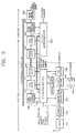
- FIG. 3 is a block diagram of a multi-media system for transferring a program number between the ATV 100 and the HD-VCR 200.
- a tuner 101 selects the frequency band of an intended program from the multi-program MPEG2-TS received via an antenna.
- a channel decoder 102 extracts the intended multi-program MPEG2-TS after removing an error correction code from the received signal.
- the multi-program MPEG2-TS extracted from the channel decoder 102 is output to a transport stream demultiplexer 103 during a display mode, and to an extra header inserter/remover 109 during a transfer mode.
- the MPEG2-TS corresponds to an MPEG2-system layer.
- One program is constituted of video information, audio information and user data information.
- video data information, audio data information and user data information corresponding to a plurality of programs are time-division multiplexed into one stream.
- the MPEG2-TS includes program specific information (PSI) such that a receiver can properly parse the audio data information, video data information and user data information corresponding to an intended program during demultiplexing.
- PSI program specific information
- PAT program association table
- PMT program map table
- CAT conditional access table
- PAT and PMT are important.
- PIDs packet identification numbers (PIDs) with respect to transport stream packets including a video stream and an audio stream of the corresponding program, are summarized by item.
- the lengths of the transport stream packets are fixed at 188 bytes.
- a transport stream demultiplexer 103 parses the PAT and PMT of the multi-program MPEG2-TS of a channel selected by the channel decoder 102.
- the transport stream demultiplexer 103 then extracts a video PID (V_PID) and an audio PID (A_PID) from the parsed PMT, to separate a video stream and an audio stream according to the video PID and the audio PID.
- the video and audio streams are output to a video decoder 104 and an audio decoder 105, respectively.
- the transport stream demultiplexer 103 parses program guide information of the multi-program MPEG2-TS of the channel selected by the channel decoder 102, and outputs the parsed information to an ATV microcomputer 106.
- the video decoder 104 decodes the separated video stream and displays the decoded image signal on a display (not shown).
- the audio decoder 105 decodes the audio stream and outputs the decoded sound signal to a sound output device (not shown) such as a speaker.
- An on-screen graphic (OSG) generator 108 mixes the program guide information with a graphic signal used as a background screen, generated by a graphic source 107, or with the image signal decoded by the video decoder 104, under the control of the ATV microcomputer 106, to display the result on a display (not shown).
- OSG on-screen graphic
- a user inputs one or a plurality of program numbers of intended programs using the ATV-remote controller 120.
- the OSG is reproduced by the ATV 100, and the same OSG is provided, regardless of the manufacturers of the connected apparatus. Also, it is unnecessary for an HD-VCR signal processor 205 of the HD-VCR 200 to parse the program guide information existing in MPEG2-TS.
- the transport stream demultiplexer 103, the video decoder 104, the audio decoder 105, the graphic source 107 and the OSG generator 108 may be called an "ATC signal processor.”
- an on-screen display (OSD) generator for generating the program guide information for an OSD may be included instead of the OSG generator 108.
- a transaction layer, an IEEE 1394 serial bus management layer, a link layer 110 and a physical layer 111 which are various layer of the IEEE 1394 protocol, may be called as a digital interface for the ATV.
- the transaction layer and the IEEE 1394 serial bus management layer are installed in the ATV microcomputer 106 as software.
- the HD-VCR 200 is roughly constituted of a digital interface including a physical layer 201, a link layer 202, a transaction layer and an IEEE 1394 serial bus management layer, an HD-VCR microcomputer 203, an extra header inserter/remover 204 and an HD-VCR signal processor 205.
- the transaction layer and the IEEE 1394 serial bus management layer are installed in the HD-VCR microcomputer 103 as software.
- the transfer of the MPEG2-TS from the ATV 100 to the HD-VCR 200 during the recording mode will be described as an example.
- the transfer of the MPEG2 is performed reversed.
- the extra header inserter/remover 109 inserts a time stamp, divides each TS packet having the time stamp into block units of a predetermined size (24 bytes), and adds a CIP header to each block, thereby constituting a data block packet for the IEEE 1394 transfer.
- the link layer 110 adds an isochronous header to the data block packet including the CIP header for the IEEE 1394 transfer, output from the extra header inserter/remover 109 to make the data block packet into an isochronous packet.
- the link layer 110 then converts the isochronous packet into a serial signal.
- the physical layer 111 converts the serial signal into an electrical signal.
- the electrical signal is input to the physical layer 201 of the digital interface of the HD-VCR, via the IEEE 1394 cable 300.
- the physical layer 201 converts the electrical signal into digital data.
- the link layer 202 converts the digital data into parallel data of a 1-byte unit and then removes the isochronous header.
- the extra header inserter/remover 204 removes the extra header (CIP header), and makes the data into a TS packet to output to the HD-VCR signal processor 205.
- the HD-VCR signal processor 205 parses the PAT from the multi-program MPEG2-TS processed into transport packets, and parses the PMT PID based on the parsed PAT using the asynchronously transferred program number.
- the PAT PID since the PAT PID is set to "0", the PAT is extracted by checking whether the PAT PID is equal to "0" or not. Also, all packets of an intended program are extracted by extracting the A_PID and the V_PID from the PMT PID to be recorded on a tape.
- the HD-VCR signal processor 205 performs signal processing for reproduction as well.
- the program information (program number) selected by a user must be transferred from the ATV-remote controller 120 to the ATV-microprocessor 106, and then to the HD-VCR 200. Since the program number is transferred once after the recording mode is set, the program number is transferred as an asynchronous packet together with a recording start command. According to the current specification proposed by the HD-VCR Conference, a command capable of transferring a program number is not defined. Thus, the present invention is intended to transfer the program number by adding a command for transferring the program number thereto.
- the program specific information excluding the program number, e.g., PMT PID, V_PID, A_PID and other information, can be transferred. This command is required for controlling the A/V apparatus as well as the AV/C CTS.
- the addition of the program number transferring command is meaningful more than decreasing the number of remote controllers for each apparatus in the multi-media system. That is, even though it is not shown in the embodiment of the present invention, it means that the HD-VCR 200 can connect to various types of external apparatuses or a network. That is, the HD-VCR 200 can accept a program number input from an external network such as the Internet, as it does a program number transferred from the ATV 100, so that the control by the network is possible. For example, suppose that the Internet includes a home page providing program guide information managed by a broadcasting station, and an ATV capable of web browsing exists at home. If a user selects a program by connecting to the home page, the corresponding program number would be transferred to the ATV of the user and then to the HD-VCR.
- an external network such as the Internet
- the Internet includes a home page providing program guide information managed by a broadcasting station, and an ATV capable of web browsing exists at home. If a user selects a program by connecting to the home page,
- a command for transferring a program number is transferred as an asynchronous packet using the asynchronous transfer mode.
- the flow of the asynchronous transfer relates to a microcomputer.
- the command for transferring a program number is implemented using the IEEE 1394 read and write transactions, wherein the write and read transactions are performed in a transaction layer which is implemented by software in the ATV microcomputer 106.
- the ATV microcomputer 106 also implements the contents related to the management of a serial bus and an application program, as well as the transaction layer, by software.
- the link layer 110 adds an asynchronous header to a program number command in order to transfer the program number command as an asynchronous packet from the ATV microcomputer 106 according to the AV/C CTS specification, and converts the command having the asynchronous header into serial data.
- the physical layer 111 converts the serial data into an electrical signal to output via the IEEE 1394 cable 300.
- the physical layer 201 as an HD-VCR digital interface converts the electrical signal into digital data.
- the link layer 202 converts the digital data into parallel data of a 1-byte unit, removes the asynchronous header, and then outputs the result to the HD-VCR microcomputer 203.
- the HD-VCR microcomputer 203 recognizes the program number command and writes the program number in a VAUX region of the tape during a recording mode, and it reads out the program number recorded in the VAUX region during a playback mode to transfer the program number to the ATV 100 via the digital interface of the HD-VCR.
- a node on the IEEE 1394 serial bus in the AV/C CTS is called a "device".
- the device is divided into sub-devices.
- a VCR device may be constituted of a VCR sub-device and a tuner sub-device.
- devices for transferring and receiving a command are called “controller” and "target”, respectively.
- the controller can transfer a command to the target.
- the commands are classified as device commands or sub-device commands, according to whether the target of the command is a device unit or a sub-device unit.
- the target receiving the command is set to respond within a predetermined time (100msec) after receiving a command.
- a command register and a response register are required.
- the command register and the response register exist in the microcomputers 106 and 203 of Figure 3 or an external memory (not shown), which are mapped at a predetermined location on the IEEE 1394 bus.
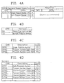
- Figure 4A shows the format of an MPEG2 information notify command for use with a system or method according to the present invention, defining a command for notifying a target (HD-VCR) of information related to the MPEG2-TS.
- a command for inquiring of whether to supply an information transfer function or not is also defined.
- a VCR device performs a single program recording, however, the command format of Figure 4A includes the commands for both single program recording and multi-program recording.
- FIG 5 shows the format of an MPEG2 information inquiry command for use with a system or method according to an embodiment of the present invention, in which a command capable of taking MPEG2-TS information from a target (HD-VCR) is defined.
- a command capable of taking MPEG2-TS information from a target HD-VCR
- each OPR is the same as those of the MPEG2 information notify command of Figures 4B to 4D.
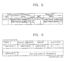
- Figure 6 shows the format of an AV/C command frame and of an AV/C response frame proposed by the cited reference [2]
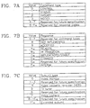
- Figures 7A to 7C are tables defining a command type, a response code and a subunit address, respectively, proposed by the cited reference [2].
- Figure 8 shows an example in which the program number of a single program is transferred from the ATV 100 to the HD-VCR 200 during a recording mode using the commands defined in Figures 4A through 4D, 5, 6 and 7A through 7C, which is performed by software in the ATV microcomputer 106 of Figure 3.
- a controller transfers a first command frame to a target (HD-VCR) to inquire (OPC:C7 16 ) whether to support (CT/RC:0010 2 ) the recording of the program number of a single program (OPR1:00 16 ) by a first VCR device (Header Address (HA) 00100 2 /000 2 ).
- the target (HD-VCR) transfers a first response frame to the controller (ATV) as a response (OPC:C7 16 ) for permitting (CT/RC:1100 2 ) the recording of the program number of the single program (OPR1:00 16 ) by the first VCR device (HA:00100 2 /000 2 ).
- the controller (ATV) receives the first response frame, and transfers a second command frame to the target (HD-VCR) to notify (OPC:C7 16 ) a command (CT/RC:0000 2 ) for recording the program number (OPR1:00 ABCD 16 ) of the program selected by a user by using the first VCR device (HA:00100 2 /000 2 ). Then, the target (HD-VCR) transfers a second response frame to the controller (ATV) to notify (OPC:C7 16 ) the permission (CT/RC:1001 2 ) of the recording of the program number (ABCD 16 ) by the first VCR device (HA: 00100 2 /000 2 ).
- Figure 9 shows an example in which the program number of a single program is received by the ATV 100 from the HD-VCR 200 during the playback mode, which is performed by the ATV microcomputer 106.
- a controller (ATV) transfers a first command frame to a target (HD-VCR) to inquire (CT/RC:0010 2 ) as to whether to notify (OPC:C8 16 ) the target (HD-VCR) of the program number of a single program (OPR1:00 16 ) recorded by a first VCR device (HA:00100 2 /000 2 ).
- the target (HD-VCR) transfers a first response frame to the controller (ATV) to notify (OPC:C8 16 ) the controller (ATV) of the permission (CT/RC:1100 2 ) of the reproduction of the single program (OPR1:00 16 ) by the first VCR device (HA:00100 2 /000 2 ).
- the controller (ATV) transfers a second command frame to the target (HD-VCR) to inquire (CT/RC:1000 2 ) as to whether to notify (OPC:C8 16 ) the target (HD-VCR) of the program number of the single program (OPR1:00 16 ) recorded by the first VCR device (HA:00100 2 /000 2 ).
- the target (HD-VCR) transfers a second response frame to the controller (ATV) to notify (CT/RC:1001 2 ) the controller (ATV) of the program number (ABCD 16 ) of the single program (OPR1:00 16 ) recorded by the first VCR device (HA:00100 2 /00 2 ).
- the remote controller of the above embodiment may include all input devices.
- the program number is transferred and received during the asynchronous transfer mode of the IEEE 1394 digital interface, so that various digital A/V apparatuses can all be controlled by one apparatus, implementing a home network.
- an OSG generator is provided in the ATV, providing a consistent OSG.
Description
- The present invention relates to a digital audio/video (A/V) apparatus, and more particularly, to a multi-media system in which a plurality of digital A/V apparatuses are connected with each other via a digital interface.
- In a digital A/V apparatus, a device can be controlled by other devices, which could not be achieved in a conventional analog A/V apparatus. As an example, the High-Definition-Digital Video Cassette Recorder (HD-DVCR) Conference defines a command set which is called AV/C CTS (Audio/Video Control Command and Transaction Set) so that an operation command from a remote controller is transferred to a target control device (called "local device") via the IEEE 1394 serial bus. Here, the IEEE 1394 serial bus is a standard related to the high-speed data transfer, which is defined by the Institute of Electrical & Electronics Engineers (IEEE). The IEEE 1394 serial bus is used as an interface for connecting each device of a digital multi-media system, having an isochronous transfer mode and an asynchronous transfer mode. Here, A/V data is transferred in real time using the isochronous transfer mode, and transactions required for communication, including read, write and lock, are transferred in an asynchronous pattern using the asynchronous transfer mode. Also, control commands such as AV/C CTS are transferred in an asynchronous pattern using the asynchronous transfer mode.
- However, the contents defined by AV/C CTS includes commands relating to a direct/indirect user's input button, but commands relating to all operations are not completed yet, and are still being updated. Also, commands related to the transfer of information which is not noticed by a user, or the notice of which is not necessary, are not yet provided. Thus, it is difficult to achieve a single common remote control for all devices.
- On the other hand, according to the articles entitled "Specification of Consumer-Use Digital VCRs using 6.3mm magnetic tapes-Part 8: ATV Specifications of Consumer-Use Digital VCR" and "Specification of Digital Interface for Consumer Electronic Audio/Video Equipment-
Parts 1 & 4", which are published by the HD-DVCR Conference, it is prescribed that an advanced television (ATV) signal having MPEG2-TS (Moving Picture Experts Group 2-Transport Stream) which is transferred using the IEEE 1394 can be recorded by an HD-VCR using 6.3mm magnetic tape. Particularly, it is prescribed to transfer the MPEG2-TS using the isochronous transfer mode of the IEEE 1394 while having a common format, i.e., common isochronous packet (CIP) header structure as in the case of a digital video cassette (DVC) called a camcoder. Here, the AV/C CTS is adopted as a control command. Also, the MPEG2 is roughly classified into one of three: MPEG2-system, MPEG2-video and MPEG2-audio. A transport stream (TS) and a program stream (PS) are defined as a transfer standard in the MPEG2-system. - Figure 1 shows a typical example of data transfer between the ATV and HD-VCR. According to the definition by [1] "Blue Book", published by the HD-DVCR Conference, including articles entitled "Specification of Consumer-Use Digital VCRs using 6.3mm magnetic tapes", "Specification of Digital Interface for Consumer Electronic Audio/Video Equipment", and "Specifications of AV/C Command and Transaction Set for Digital Interface", A/V data transferred from an
ATV 10 to HD-VCR 20 which are connected by an IEEE 1394cable 30 during a recording mode, is a multi-program MPEG2-TS, and data transferred from the HD-VCR 20 to theATV 10 during a playback mode is a single program MPEG2-TS. Here, the term ATV refers to the American high definition television (HDTV) suggested by the Advanced Television Systems Committee (ATSC). Also, the AV/C CTS suggested in the Blue Book defines control commands with respect to VCR sub-devices, most of which relate to mechanical operation. - For example, commands from a
remote controller 11 for the ATV 10, such as fast-forward and rewind, can be transferred to the HD-VCR 20 via the IEEE 1394 serial bus. However, control commands to the VCR sub-devices do not include commands for transferring information related to an MPEG2 system layer, e.g., program number. - Thus, the MPEG2-TS is transferred from the
ATV 10 to the HD-VCR 20 during the recording mode. Here, the HD-VCR 20 should receive information required for parsing the MPEG2-TS being transferred from theATV 10, from a user using aremote controller 21 for HD-VCR 20. - Also, the recorded single program MPEG2-TS is transferred from the HD-
VCR 20 to theATV 10 during the playback mode. Here, a program number recorded in a video auxiliary (VAUX) region should be transferred from the HD-VCR 20 to the ATV. Additionally, it is prescribed in the Blue Book to record the program number in the VAUX region of a tape. - However, the multi-media system of Figure 1 requires a separate remote controller for each device connected to the ATV. That is, when a plurality of devices, being capable of recording/reproducing a received signal, are connected to the ATV, there is an inconvenience in that an operational command should be input to each recording/reproducing device by the user, using a different remote controller for each device.
- Also, when selecting a program by parsing a program guide information (PG) for the MPEG2-TS in the multi-media system shown in Figure 1, the HD-
VCR 20 should first parse the program guide information in the multi-program MPEG2-TS transferred from the ATV. In order to display the parsed program guide information on an on-screen graphic (OSG) display, the OSG of the program guide information is transferred to theATV 10 by being MPEG2-TS encoded since there is no OSG transfer standard in the IEEE 1394. Then, a user can input a program number corresponding to an intended program, using an up/down key of theremote controller 21 for the HD-VCR while viewing the OSG displayed on theATV 10. Thus, this multi-media system requires an extra encoding circuit in the HD-VCR 20, for the MPEG2-TS encoding of the OSG, and the ability to parse the program guide information from MPEG2-TS in order to constitute the OSG. Also, the generation of the OSG is dependent on the VCR manufacturer, so it is difficult to provide the same OSG consistently. Although the ATV parses the program guide information in transferred MPEG2-TS and displays the parsed program guide information on an OSG display, and a user inputs a program number using theremote controller 11 for the ATV, the program number can not be transferred to the HD-VCR 20, since no command is defined for transferring the program number to the HD-VCR 20. -
EP 0 749 244 discloses a method for receiving a broadcast, the method including steps of: receiving a digital signal obtained by multiplexing at least one program; selecting data corresponding to one program among the at least one program multiplexed in the digital signal; decoding the selected data; and selecting data corresponding to at least one program among the at least one program multiplexed in the digital signal and transmitting the selected data to an external device. - It is an aim of embodiments of the present invention to provide a multi-media system for transferring a program number between a plurality of digital A/V apparatuses having a digital interface, and to provide a multi-media system capable of performing the method.
- Advantageously, preferred embodiments of the present invention provide a multi-media system for receiving a program number between a plurality of digital A/V apparatuses having a digital interface, in an asynchronous transfer mode.
- Advantageously, embodiments of the present invention provide a multi-media system in which a receiver, for receiving an MPEG2-TS, parses program guide information of the MPEG2-TS and displays the parsed information on an on-screen graphic (OSG) display, and then transfers a command with respect to the input program number to a recording/reproducing device.
- Advantageously, embodiments of the present invention provide a method for transferring a program number during a recording mode, using an asynchronous transfer mode, in the MPEG2-TS transfer between a plurality of digital A/V apparatuses having a digital interface.
- According to a first aspect of the invention, there is provided a multi-media system having at least a receiver for receiving a transport stream and a recording/reproducing device for recording/reproducing selected programs in the transport stream, wherein the receiver comprises:
- a first signal processor for parsing program specific information (PSI) of the received transport stream and decoding a video signal and an audio signal of a program intended for display, based on the parsed PSI;
- an input device for entering one or more program numbers of programs intended for display or recording/reproducing; and a first digital interface for generating a program number command based on a program number received from the input device being the number of a program intended for recording/reproducing, for transferring the program number command, and for transferring the transport stream, and wherein the recording/reproducing device comprises:
- a second digital interface for decoding the program number command transferred via the first digital interface and for receiving the transport stream being transferred via the first digital interface; and
- a second signal processor for extracting from the transport steam received by the second digital interface a program intended for recording, based on the program number command, and for recording the extracted result on recording media during a recording mode, and for supplying to the second digital interface during a reproducing mode a program reproduced from the recording media based on a program number command received from the first digital interface.
-
- The input device is preferably a remote controller.
- The receiver may be connected to one to more recording/reproducing devices using the digital interface and the recording/reproducing devices may be controlled by the input device.
- The first digital interface may generate a command based on the parsed PSI.
- The first and second digital Interfaces are preferably an IEEE 1394 interface, respectively.
- The first digital interface preferably transfers the transport stream as isochronous packets during an isochronous transfer mode, and transfers the program number as asynchronous packets during an asynchronous transfer mode using a control command set.
- The control command set is preferably an audio/video control command and transaction set (AV/C CTS)
- The first digital interface may transfer a multi-program transport stream as isochronous packets in an isochronous transfer mode, and the second digital interface may transfer either a single program or multi-program transport stream as isochronous packets in the isochronous transfer mode during a playback mode.
- The first digital interface may transfer a single program transport stream as isochronous packets in an isochronous transfer mode, and the second digital interface transfer a single program transport stream as isochronous packets in the isochronous transfer mode during a playback mode.
- The first digital interface preferably comprises: a first microcomputer including a transaction layer and a serial bus management layer as software, for generating a program number command based on a program number received from the input device, using a write transaction and a read transaction; a first link layer for adding an asynchronous header to the program number command received from the first microcomputer to convert the program number command into serial data; and a first physical layer for converting the serial data into an electrical signal.
- The receiver may further comprise a first extra header inserter/remover for inserting an extra header into a transport stream being received, to form a data block packet provided by the first digital interface for the IEEE 1394 transfer, and for removing the extra header inserted into a reproduced data block packet for the IEEE 1394 transfer.
- The second digital interface may comprise: a second physical layer for converting the program number command electrical signal, transferred from the first physical layer, into digital data; a second link layer for converting the program number command digital data into parallel data, and for removing an asynchronous header; and a second microcomputer including a transaction layer and a serial bus management layer as software, for recording the program number on a predetermined region of a recording medium by recognizing the program number command during a recording mode, and for reading out the program number recorded in the predetermined region during a playback mode.
- The recording/reproducing device preferably further comprises a second extra header inserter/remover for removing an extra header inserted into a data block packet provided by the second digital interface for a IEEE 1394 transfer, and for inserting an extra header into the transport stream reproduced from the second signal processor, to form the data block packet for the IEEE 1394 transfer.
- The first signal processor preferably further comprises an on-screen graphic (OSG) generator for displaying program guide information of a transport stream being received on an OSG display.
- The OSG generator may mix the program guide information with a graphic signal of a background screen or with the decoded video signal to be provided to the OSG display.
- The first signal processor may further comprise an on-screen display (OSD) generator for displaying the program guide information of a transport stream being received on an OSD display.
- The second signal processor preferably does not, parse program guide information from a transport stream being received via the second digital interface.
- According to a second aspect of the invention there is provided a method for transferring a program number between a receiver for receiving a transport stream and a recording/reproducing device, wherein each of the receiver and recording/reproducing device has a digital interface, the method comprising the steps of:
- (a) inputting in the receiver the program number of an program intended to be recorded or reproduced; and
- (b) generating in the digital interface of the receiver a program number command based on the input program number, and transferring said program number command from the digital interface of the receiver to the digital interface of the recording/reproducing device. whereby in recording mode the program number command received from the digital interface of the receiver is used by the recording/reproducing device to extract from the transport stream the program corresponding to the input program number and the recording/reproducing device records said program on a recording medium, and in reproducing mode the program number command received from the digital interface of the receiver is used by the recording/reproducing device to reproduce from the recording medium the program corresponding to the program number input in the receiver, the program being transferred to the receiver through the digital interfaces.
-
- The step (a) comprises preferably the steps of: (a1) parsing program guide information from the transport stream; (a2) displaying the parsed program guide information; and (a3) providing the program number of the intended program according to the displayed program guide information.
- Step (a2) preferably comprises displaying, the parsed program guide information on an OSG display.
- The step (a2) may comprise displaying the parsed program guide information on an OSD display.
- For a better understanding of the invention, and to show how embodiments of the same may be carried into effect, reference will now be made, by way of example, to the accompanying diagrammatic drawings, in which:
- Figure 1 is a diagram illustrating a conventional method for MPEG2-TS transfer between an ATV and an HD-VCR;
- Figure 2 is a diagram illustrating a method for MPEG2-TS transfer between an ATV and an HD-VCR according to aspects of the present invention;
- Figure 3 is a block diagram of a multi-media system for transferring and receiving a program number, according to a preferred embodiment of the present invention.
- Figures 4A through 4D show formats of an MPEG2 information notify command for transferring a program number in a system or method according to embodiments of the present invention;
- Figure 5 shows the format of an MPEG2 information inquiry command for receiving a program number, in a system or method according to embodiments of the present invention;
- Figure 6 shows the format of the commands of a command frame and a response frame, according to the AV/C CTS specification, for easy understanding of in a system or method embodiments of the present invention;
- Figures 7A through 7C are tables respectively defining a command type, a response code and a subunit address according to the AV/C CTS specification, for constituting the command frame and the response frame shown in Figure 6;
- Figure 8 is a diagram showing an example of transferring a program number of a single program during a recording mode; and
- Figure 9 is a diagram showing an example of receiving a program number of a single program during a playback mode.
-
- For convenience of explanation, an advanced television (ATV) will be described as an example of an MPEG2-TS broadcasting signal receiver, and a high definition videocassette recorder (HD-VCR) will be described as an example of an MPEG2-TS recording/reproducing device. However, any apparatus having a digital interface capable of transferring/receiving an MPEG2-TS, can replace the ATV, and any MPEG-2-TS recording/reproducing device can replace the HD-VCR, for the purposes described below.
- Also, in order to simplify the structure of the multi-media system shown in Figure 2, only an HD-
VCR 200 and anATV 100 are connected by an IEEE 1394cable 300. However, other digital audio/video apparatuses may be connected to theATV 100 and/or the HD-VCR 200 by the IEEE 1394cable 300. In the multi-media system of Figure 2, oneremote controller 120 for the ATV (ATV-remote controller) is used. During a recording mode, a multi-program MPEG2-TS is transferred from theATV 100 to the HD-VCR 200. During a playback mode, a single program MPEG2-TS is transferred from the HD-VCR 200 to theATV 100. - However, a single program MPEG2-TS may be transferred from the
ATV 100 to the HD-VCR 200 during the recording mode, and from the HD-VCR 200 to theATV 100 during the playback mode. Also, a multi-program MPEG2-TS may be transferred from theATV 100 to the HD-VCR 200 during the recording mode, and from the HD-VCR 200 to theATV 100 during the playback mode. - According to embodiments of the present invention, one or a plurality of program numbers input by the ATV-
remote controller 120 is transferred as a command during the IEEE 1394 asynchronous transfer mode, and the program number recorded on a tape is transferred from the HD-VCR 200 to theATV 100 during the playback of the MPEG2-TS, such that the HD-VCR 200 is controlled by theATV 100. To achieve this, a new command for transferring a program number should be added to the AV/C CTS, and the new command is transferred from theATV 100 and the HD-VCR 200 using the asynchronous transfer mode of the IEEE 1394. - Figure 3 is a block diagram of a multi-media system for transferring a program number between the
ATV 100 and the HD-VCR 200. In Figure 3, atuner 101 selects the frequency band of an intended program from the multi-program MPEG2-TS received via an antenna. Achannel decoder 102 extracts the intended multi-program MPEG2-TS after removing an error correction code from the received signal. The multi-program MPEG2-TS extracted from thechannel decoder 102 is output to atransport stream demultiplexer 103 during a display mode, and to an extra header inserter/remover 109 during a transfer mode. Here, the MPEG2-TS corresponds to an MPEG2-system layer. - Here, the MPEG2 system layer will be described briefly for easy understanding of the embodiment of the present invention. One program is constituted of video information, audio information and user data information. According to the MPEG2-TS defined by the MPEG2 system layer, video data information, audio data information and user data information corresponding to a plurality of programs are time-division multiplexed into one stream. The MPEG2-TS includes program specific information (PSI) such that a receiver can properly parse the audio data information, video data information and user data information corresponding to an intended program during demultiplexing.
- Most of the PSI is in table form, such as the program association table (PAT), program map table (PMT) and conditional access table (CAT). Here, the PAT and PMT are important. One PMT exists per program. In the PMT, packet identification numbers (PIDs) with respect to transport stream packets including a video stream and an audio stream of the corresponding program, are summarized by item. Here, the video stream of the program is represented by PID=XXXX , and the audio stream thereof is represented by PID=YYYY . The lengths of the transport stream packets are fixed at 188 bytes.
- Since a plurality of programs exist in one transport stream (TS), a plurality of PMTs exist in the TS. Thus, a synthetic table is required, for connecting each program of the TS with the PHT PIDs of each program. This synthetic table is called the "PAT". Since one program is expressed as one program number, items of the PAT are constituted of information giving the relationship between the program number(=XXXX) and the PMT PID.
- On the other hand, a
transport stream demultiplexer 103 parses the PAT and PMT of the multi-program MPEG2-TS of a channel selected by thechannel decoder 102. Thetransport stream demultiplexer 103 then extracts a video PID (V_PID) and an audio PID (A_PID) from the parsed PMT, to separate a video stream and an audio stream according to the video PID and the audio PID. The video and audio streams are output to avideo decoder 104 and anaudio decoder 105, respectively. Also, thetransport stream demultiplexer 103 parses program guide information of the multi-program MPEG2-TS of the channel selected by thechannel decoder 102, and outputs the parsed information to anATV microcomputer 106. - The
video decoder 104 decodes the separated video stream and displays the decoded image signal on a display (not shown). Theaudio decoder 105 decodes the audio stream and outputs the decoded sound signal to a sound output device (not shown) such as a speaker. - An on-screen graphic (OSG)
generator 108 mixes the program guide information with a graphic signal used as a background screen, generated by agraphic source 107, or with the image signal decoded by thevideo decoder 104, under the control of theATV microcomputer 106, to display the result on a display (not shown). Here, a user inputs one or a plurality of program numbers of intended programs using the ATV-remote controller 120. The OSG is reproduced by theATV 100, and the same OSG is provided, regardless of the manufacturers of the connected apparatus. Also, it is unnecessary for an HD-VCR signal processor 205 of the HD-VCR 200 to parse the program guide information existing in MPEG2-TS. - Here, the
transport stream demultiplexer 103, thevideo decoder 104, theaudio decoder 105, thegraphic source 107 and theOSG generator 108 may be called an "ATC signal processor." Also, an on-screen display (OSD) generator for generating the program guide information for an OSD may be included instead of theOSG generator 108. - On the other hand, a transaction layer, an IEEE 1394 serial bus management layer, a
link layer 110 and aphysical layer 111, which are various layer of the IEEE 1394 protocol, may be called as a digital interface for the ATV. Here, the transaction layer and the IEEE 1394 serial bus management layer are installed in theATV microcomputer 106 as software. The HD-VCR 200 is roughly constituted of a digital interface including aphysical layer 201, alink layer 202, a transaction layer and an IEEE 1394 serial bus management layer, an HD-VCR microcomputer 203, an extra header inserter/remover 204 and an HD-VCR signal processor 205. Here, the transaction layer and the IEEE 1394 serial bus management layer are installed in the HD-VCR microcomputer 103 as software. - Next, the MPEG2-TS transfer during the isochronous transfer mode, and the transfer and reception of the program number during the asynchronous transfer mode, via the IEEE 1394 serial bus, will be described.
- The transfer of the MPEG2-TS from the
ATV 100 to the HD-VCR 200 during the recording mode will be described as an example. During the playback mode, the transfer of the MPEG2 is performed reversed. In order to transfer the 188-byte multi-program MPEG2-TS packets output from thechannel decoder 102 via the IEEE 1394 interface, the extra header inserter/remover 109 inserts a time stamp, divides each TS packet having the time stamp into block units of a predetermined size (24 bytes), and adds a CIP header to each block, thereby constituting a data block packet for the IEEE 1394 transfer. Thelink layer 110 adds an isochronous header to the data block packet including the CIP header for the IEEE 1394 transfer, output from the extra header inserter/remover 109 to make the data block packet into an isochronous packet. Thelink layer 110 then converts the isochronous packet into a serial signal. Thephysical layer 111 converts the serial signal into an electrical signal. - The electrical signal is input to the
physical layer 201 of the digital interface of the HD-VCR, via the IEEE 1394cable 300. Thephysical layer 201 converts the electrical signal into digital data. Thelink layer 202 converts the digital data into parallel data of a 1-byte unit and then removes the isochronous header. The extra header inserter/remover 204 removes the extra header (CIP header), and makes the data into a TS packet to output to the HD-VCR signal processor 205. For selecting a single program, the HD-VCR signal processor 205 parses the PAT from the multi-program MPEG2-TS processed into transport packets, and parses the PMT PID based on the parsed PAT using the asynchronously transferred program number. That is, since the PAT PID is set to "0", the PAT is extracted by checking whether the PAT PID is equal to "0" or not. Also, all packets of an intended program are extracted by extracting the A_PID and the V_PID from the PMT PID to be recorded on a tape. Here, the HD-VCR signal processor 205 performs signal processing for reproduction as well. - For the above operation by the HD-
VCR signal processor 205, the program information (program number) selected by a user must be transferred from the ATV-remote controller 120 to the ATV-microprocessor 106, and then to the HD-VCR 200. Since the program number is transferred once after the recording mode is set, the program number is transferred as an asynchronous packet together with a recording start command. According to the current specification proposed by the HD-VCR Conference, a command capable of transferring a program number is not defined. Thus, the present invention is intended to transfer the program number by adding a command for transferring the program number thereto. Also, the program specific information (PSI) excluding the program number, e.g., PMT PID, V_PID, A_PID and other information, can be transferred. This command is required for controlling the A/V apparatus as well as the AV/C CTS. - The addition of the program number transferring command is meaningful more than decreasing the number of remote controllers for each apparatus in the multi-media system. That is, even though it is not shown in the embodiment of the present invention, it means that the HD-
VCR 200 can connect to various types of external apparatuses or a network. That is, the HD-VCR 200 can accept a program number input from an external network such as the Internet, as it does a program number transferred from theATV 100, so that the control by the network is possible. For example, suppose that the Internet includes a home page providing program guide information managed by a broadcasting station, and an ATV capable of web browsing exists at home. If a user selects a program by connecting to the home page, the corresponding program number would be transferred to the ATV of the user and then to the HD-VCR. - A command for transferring a program number, proposed by the present invention, is transferred as an asynchronous packet using the asynchronous transfer mode. Here, the flow of the asynchronous transfer relates to a microcomputer.
- The command for transferring a program number is implemented using the IEEE 1394 read and write transactions, wherein the write and read transactions are performed in a transaction layer which is implemented by software in the
ATV microcomputer 106. TheATV microcomputer 106 also implements the contents related to the management of a serial bus and an application program, as well as the transaction layer, by software. - The
link layer 110 adds an asynchronous header to a program number command in order to transfer the program number command as an asynchronous packet from theATV microcomputer 106 according to the AV/C CTS specification, and converts the command having the asynchronous header into serial data. Thephysical layer 111 converts the serial data into an electrical signal to output via the IEEE 1394cable 300. - The
physical layer 201 as an HD-VCR digital interface converts the electrical signal into digital data. Thelink layer 202 converts the digital data into parallel data of a 1-byte unit, removes the asynchronous header, and then outputs the result to the HD-VCR microcomputer 203. The HD-VCR microcomputer 203 recognizes the program number command and writes the program number in a VAUX region of the tape during a recording mode, and it reads out the program number recorded in the VAUX region during a playback mode to transfer the program number to theATV 100 via the digital interface of the HD-VCR. - Next, a control command for the program number generated according to the AV/C CTS specification will be described in detail. Here, the AV/C CTS specification is disclosed in the reference [2] entitled "Specification of Digital Interface for Consumer Electronic Audio/Video Equipment" (called IEC1883).
- According to the above cited reference [2], a node on the IEEE 1394 serial bus in the AV/C CTS is called a "device". The device is divided into sub-devices. For example, a VCR device may be constituted of a VCR sub-device and a tuner sub-device. Also, devices for transferring and receiving a command are called "controller" and "target", respectively. The controller can transfer a command to the target. There are a control command, a status inquiry command, a support inquiry command and a report notify command. Also, the commands are classified as device commands or sub-device commands, according to whether the target of the command is a device unit or a sub-device unit. The target receiving the command is set to respond within a predetermined time (100msec) after receiving a command. For a smooth transfer of commands and responses between two devices, a command register and a response register are required. The command register and the response register exist in the
microcomputers - Figure 4A shows the format of an MPEG2 information notify command for use with a system or method according to the present invention, defining a command for notifying a target (HD-VCR) of information related to the MPEG2-TS. In this format, a command for inquiring of whether to supply an information transfer function or not is also defined. Generally, a VCR device performs a single program recording, however, the command format of Figure 4A includes the commands for both single program recording and multi-program recording.
- In Figures 4A to 4D, "OPC" presents an operation code, "OPR" represents an operand, and "R" and "O" of the "level" column are abbreviations of "recommended" and "optional", respectively. Also, "XX" represents that the OPR differs according to the cases. Figures 4B to 4D define the OPRs of the command of Figure 4A.
- Figure 5 shows the format of an MPEG2 information inquiry command for use with a system or method according to an embodiment of the present invention, in which a command capable of taking MPEG2-TS information from a target (HD-VCR) is defined. Here, each OPR is the same as those of the MPEG2 information notify command of Figures 4B to 4D.
- Figure 6 shows the format of an AV/C command frame and of an AV/C response frame proposed by the cited reference [2], and Figures 7A to 7C are tables defining a command type, a response code and a subunit address, respectively, proposed by the cited reference [2].
- Figure 8 shows an example in which the program number of a single program is transferred from the
ATV 100 to the HD-VCR 200 during a recording mode using the commands defined in Figures 4A through 4D, 5, 6 and 7A through 7C, which is performed by software in theATV microcomputer 106 of Figure 3. - In Figure 8, when a program number is input by a user during the recording mode, a controller (ATV) transfers a first command frame to a target (HD-VCR) to inquire (OPC:C716) whether to support (CT/RC:00102) the recording of the program number of a single program (OPR1:0016) by a first VCR device (Header Address (HA) 001002/0002). Then, the target (HD-VCR) transfers a first response frame to the controller (ATV) as a response (OPC:C716) for permitting (CT/RC:11002) the recording of the program number of the single program (OPR1:0016) by the first VCR device (HA:001002/0002).
- The controller (ATV) receives the first response frame, and transfers a second command frame to the target (HD-VCR) to notify (OPC:C716) a command (CT/RC:00002) for recording the program number (OPR1:00 ABCD16) of the program selected by a user by using the first VCR device (HA:001002/0002). Then, the target (HD-VCR) transfers a second response frame to the controller (ATV) to notify (OPC:C716) the permission (CT/RC:10012) of the recording of the program number (ABCD16) by the first VCR device (HA: 001002/0002).
- Figure 9 shows an example in which the program number of a single program is received by the
ATV 100 from the HD-VCR 200 during the playback mode, which is performed by theATV microcomputer 106. - In Figure 9, when the playback mode is set, a controller (ATV) transfers a first command frame to a target (HD-VCR) to inquire (CT/RC:00102) as to whether to notify (OPC:C816) the target (HD-VCR) of the program number of a single program (OPR1:0016) recorded by a first VCR device (HA:001002/0002). Here, the target (HD-VCR) transfers a first response frame to the controller (ATV) to notify (OPC:C816) the controller (ATV) of the permission (CT/RC:11002) of the reproduction of the single program (OPR1:0016) by the first VCR device (HA:001002/0002).
- Then, the controller (ATV) transfers a second command frame to the target (HD-VCR) to inquire (CT/RC:10002) as to whether to notify (OPC:C816) the target (HD-VCR) of the program number of the single program (OPR1:0016) recorded by the first VCR device (HA:001002/0002). Here, the target (HD-VCR) transfers a second response frame to the controller (ATV) to notify (CT/RC:10012) the controller (ATV) of the program number (ABCD16) of the single program (OPR1:0016) recorded by the first VCR device (HA:001002/002).
- The remote controller of the above embodiment may include all input devices.
- As described above, in the multi-media system according to the present invention, the program number is transferred and received during the asynchronous transfer mode of the IEEE 1394 digital interface, so that various digital A/V apparatuses can all be controlled by one apparatus, implementing a home network. Also, an OSG generator is provided in the ATV, providing a consistent OSG.
Claims (22)
- A multi-media system having at least a receiver (100) for receiving a transport stream and a recording/reproducing device (200) for recording/reproducing selected programs in the transport stream, wherein the receiver (100) comprises:wherein the recording/reproducing device (200) comprises :a first signal processor (103-105) for parsing program specific information (PSI) of the received transport stream and decoding a video signal and an audio signal of a program intended for display, based on the parsed PSI;an input device (120) for entering one or more program numbers of programs intended for display or recording/reproducing; anda first digital interface (106, 110, 111) for generating a program number command based on a program number received from the input device being the number of a program intended for recording/reproducing, for transferring the program number command, and for transferring the transport stream , anda second digital interface (201-203) for decoding the program number command transferred via the first digital interface and for receiving the transport stream being transferred via the first digital interface; anda second signal processor (205) for extracting from the transport steam received by the second digital interface (201-203) a program intended for recording, based on the program number command, and for recording the extracted result on recording media during a recording mode, and for supplying to the second digital interface (201-203) during reproducing mode a program reproduced from the recording media based on a program number command received from the first digital interface.
- The multi-media system of claim 1, wherein the input device (120) is a remote controller.
- The multi-media system of claim 1 or 2, wherein the receiver (100) is connected to one or more recording/reproducing devices (200) using the digital interface and the recording/reproducing devices are controlled by the input device (120).
- The multi-media system of claim 1, 2, or 3, wherein the first digital interface (106, 110, 111) generates a command based on the parsed PSI.
- The multi-media system of claim 1, 2, 3, or 4, wherein the first and second digital interfaces (106, 110, 111); (201-203) are an IEEE 1394 interface, respectively.
- The multi-media system of any of claims 1 to 5, wherein the first digital interface (106, 110, 111) transfers the transport stream as isochronous packets during an isochronous transfer mode, and transfers the program number as asynchronous packets during an asynchronous transfer mode using a control command set.
- The multi-media system of claim 6, wherein the control command set is an audio/video control command and transaction set (AV/C CTS).
- The multi-media system of any of claims 1 to 7, wherein the first digital interface (106, 110, 111) transfers a multi-program transport stream as isochronous packets in an isochronous transfer mode, and the second digital interface (201-203) transfers a single program transport stream as isochronous packets in the isochronous transfer mode during a playback mode.
- The multi-media system of any of claims 1 to 7, wherein the first digital interface (106, 110, 111) transfers a multi-program transport stream as isochronous packets in an isochronous transfer mode, and the second digital interface (201-203) transfers a multi-program transport stream as isochronous packets in the isochronous transfer mode during a playback mode.
- The multi-media system of any of claims 1 to 7, wherein the first digital interface (106, 110, 111) transfers a single program transport stream as isochronous packets in an isochronous transfer mode, and the second digital interface (201-203) transfers a single program transport stream as isochronous packets in the isochronous transfer mode during a playback mode.
- The multi-media system of claim 5 or any of claims 6 to 10 as dependent thereon, wherein the first digital interface comprises:a first microcomputer (106) including a transaction layer and a serial bus management layer as software, for generating a program number command based on a program number received from the input device (120), using a write transaction and a read transaction;a first link layer (110) for adding an asynchronous header to the program number command received from the first microcomputer (106) to convert the program number command into serial data; anda first physical layer (111) for converting the serial data into an electrical signal.
- The multi-media system of claim 11, wherein the receiver further comprises a first extra header inserter/remover (109) for inserting an extra header into a transport stream being received, to form a data block packet provided by the first digital interface (106, 110, 111) for the IEEE 1394 transfer, and for removing the extra header inserted into a reproduced data block packet for the IEEE 1394 transfer.
- The multi-media system of claim 5, wherein the second digital interface (201-203) comprises:a second physical layer (201) for converting the program number command electrical signal, transferred from the first physical layer, into digital data;a second link layer (202) for converting the program number command digital data into parallel data, and for removing an asynchronous header; anda second microcomputer (203) including a transaction layer and a serial bus management layer as software, for recording the program number on a predetermined region of a recording medium by recognizing the program number command during a recording mode, and for reading out the program number recorded in the predetermined region during a playback mode.
- The multi-media system of claim 13, wherein the recording/reproducing device (200) further comprises a second extra header inserter/remover (204) for removing an extra header inserted into a data block packet provided by the second digital interface (201-203) for a IEEE 1394 transfer, and for inserting an extra header into the transport stream reproduced from the second signal processor (205), to form the data block packet for the IEEE 1394 transfer.
- The multi-media system of claim 1, wherein the first signal processor further comprises an on-screen graphic (OSG) generator (108) for displaying program guide information of a transport stream being received on an OSG display.
- The multi-media system of claim 15, wherein the OSG generator mixes (108) the program guide information with a graphic signal of a background screen to be provided to the OSG display.
- The multi-media system of claim 15, wherein the OSG generator (108) mixes the program guide information with the decoded video signal to be provided to the OSG display.
- The multi-media system of claim 1, wherein the first signal processor further comprises an on-screen display (OSD) generator for displaying the program guide information of a transport stream being received on an OSD display.
- The multi-media system of claim 15, wherein the second signal processor (205) does not parse program guide information from a transport stream being received via the second digital interface (201-203).
- A method for transferring a program number between a receiver for receiving a transport stream and a recording/reproducing device, wherein each of the receiver and recording/reproducing device has a digital interface, the method comprising the steps of:(a) inputting in the receiver the program number of a program intended to be recorded or reproduced; and(b) generating in the digital interface of the receiver a program number command based on the input program number, and transferring said program number command from the digital interface of the receiver to the digital interface of the recording/reproducing device, whereby in recording mode the program number command received from the digital interface of the receiver is used by the recording/reproducing device to extract from the transport stream the program corresponding to the input program number and the recording/reproducing device records the said program on a recording medium, and in reproducing mode the program number command received from the digital interface of the receiver is used by the recording/reproducing device to reproduce from the recording medium the program corresponding to the program number input in the receiver, the program being transferred to the receiver through the digital interfaces.
- The method of claim 20, wherein the step (a) comprises the steps of:(a1) parsing program guide information from the transport stream;(a2) displaying the parsed program guide information; and(a3) inputting the program number of the intended program according to the displayed program guide information.
- The method of claim 21, wherein in the step (a2), the parsed program guide information is displayed on an OSG display.
Priority Applications (1)
| Application Number | Priority Date | Filing Date | Title |
|---|---|---|---|
| EP20040000208 EP1420581A1 (en) | 1997-04-14 | 1997-09-24 | Multimedia system for transferring and receiving program number and methods therefor |
Applications Claiming Priority (2)
| Application Number | Priority Date | Filing Date | Title |
|---|---|---|---|
| KR9713586 | 1997-04-14 | ||
| KR1019970013586A KR100230281B1 (en) | 1997-04-14 | 1997-04-14 | Multi-media system for transmitting and receiving a program number and method for transmitting and receiving a program number |
Related Child Applications (1)
| Application Number | Title | Priority Date | Filing Date |
|---|---|---|---|
| EP20040000208 Division EP1420581A1 (en) | 1997-04-14 | 1997-09-24 | Multimedia system for transferring and receiving program number and methods therefor |
Publications (3)
| Publication Number | Publication Date |
|---|---|
| EP0873009A2 EP0873009A2 (en) | 1998-10-21 |
| EP0873009A3 EP0873009A3 (en) | 1998-12-16 |
| EP0873009B1 true EP0873009B1 (en) | 2005-11-02 |
Family
ID=19502676
Family Applications (2)
| Application Number | Title | Priority Date | Filing Date |
|---|---|---|---|
| EP19970307437 Expired - Lifetime EP0873009B1 (en) | 1997-04-14 | 1997-09-24 | Multimedia system for transferring and receiving program number and methods therefor |
| EP20040000208 Withdrawn EP1420581A1 (en) | 1997-04-14 | 1997-09-24 | Multimedia system for transferring and receiving program number and methods therefor |
Family Applications After (1)
| Application Number | Title | Priority Date | Filing Date |
|---|---|---|---|
| EP20040000208 Withdrawn EP1420581A1 (en) | 1997-04-14 | 1997-09-24 | Multimedia system for transferring and receiving program number and methods therefor |
Country Status (6)
| Country | Link |
|---|---|
| US (2) | US7162145B2 (en) |
| EP (2) | EP0873009B1 (en) |
| JP (1) | JP2912899B2 (en) |
| KR (1) | KR100230281B1 (en) |
| CN (2) | CN1257461C (en) |
| DE (1) | DE69734502T2 (en) |
Cited By (3)
| Publication number | Priority date | Publication date | Assignee | Title |
|---|---|---|---|---|
| US8302100B2 (en) | 2000-01-18 | 2012-10-30 | Galactic Computing Corporation Bvi/Bc | System for balance distribution of requests across multiple servers using dynamic metrics |
| US8316131B2 (en) | 2000-11-10 | 2012-11-20 | Galactic Computing Corporation Bvi/Bc | Method and system for providing dynamic hosted service management across disparate accounts/sites |
| US8429049B2 (en) | 2000-07-17 | 2013-04-23 | Galactic Computing Corporation Bvi/Ibc | Method and system for allocating computing resources |
Families Citing this family (37)
| Publication number | Priority date | Publication date | Assignee | Title |
|---|---|---|---|---|
| KR100230281B1 (en) * | 1997-04-14 | 1999-11-15 | 윤종용 | Multi-media system for transmitting and receiving a program number and method for transmitting and receiving a program number |
| CN1182710C (en) * | 1997-09-18 | 2004-12-29 | 汤姆森消费电子有限公司 | Peripheral electronic device and system for controlling this device via digital bus |
| AU762427B2 (en) * | 1997-11-25 | 2003-06-26 | Thomson Licensing S.A. | Device interoperability utilizing bit-mapped on-screen display menus |
| US7068920B1 (en) | 1998-02-04 | 2006-06-27 | Thomson Licensing | Digital baseband interface for a DVD player |
| ES2332076T3 (en) * | 1998-02-04 | 2010-01-25 | Thomson Consumer Electronics, Inc. | BASE BAND INTERFACE FOR DVD PLAYER. |
| US6816491B1 (en) * | 1998-11-04 | 2004-11-09 | Hitachi, Ltd. | Multiplexed audio data decoding apparatus and receiver apparatus |
| US6671290B1 (en) * | 1998-11-10 | 2003-12-30 | Sony Corporation | Receiving apparatus and recording/reproducing system for digital broadcasts |
| US7362381B1 (en) | 1998-11-20 | 2008-04-22 | Thomson Licensing | Device interoperability utilizing bit-mapped on-screen display menus |
| EP1021048A3 (en) * | 1999-01-14 | 2002-10-02 | Kabushiki Kaisha Toshiba | Digital video recording system and its recording medium |
| US6490002B1 (en) * | 1999-02-03 | 2002-12-03 | Sony Corporation | Supplemental data path for supporting on-screen displays from external sources in a monitor/TV receiver using a secondary analog signal path |
| US7024100B1 (en) * | 1999-03-26 | 2006-04-04 | Matsushita Electric Industrial Co., Ltd. | Video storage and retrieval apparatus |
| AU4185800A (en) * | 1999-03-30 | 2000-10-16 | Tivo, Inc. | Multimedia program bookmarking system |
| CN1190014C (en) * | 1999-07-09 | 2005-02-16 | 索尼公司 | Receiver and method of reception |
| KR100331825B1 (en) * | 1999-07-27 | 2002-04-09 | 구자홍 | apparatus and method for transmitting transmission stream in digital interface |
| KR100357095B1 (en) * | 1999-07-27 | 2002-10-18 | 엘지전자 주식회사 | method and apparatus for transmitting program information in digital interface |
| US7032024B1 (en) * | 1999-07-29 | 2006-04-18 | Samsung Electronics Co., Ltd. | Connection management method for devices connected digital interface and command structure therefor |
| KR100620186B1 (en) * | 1999-09-21 | 2006-09-01 | 엘지전자 주식회사 | Method and apparatus for generating command frame and response frame in digital interface |
| JP4501187B2 (en) * | 1999-10-22 | 2010-07-14 | ソニー株式会社 | Information processing apparatus, information processing system, and information processing method |
| JP4660877B2 (en) | 2000-01-11 | 2011-03-30 | ソニー株式会社 | Electronic equipment system |
| JP2001237860A (en) * | 2000-02-21 | 2001-08-31 | Sony Corp | Communication control method and communication controller |
| KR100840960B1 (en) * | 2000-07-17 | 2008-06-24 | 갈랙틱 컴퓨팅 코포레이션 비브이아이/아이비씨 | Method and system for providing dynamic hosted service management |
| JP2002051307A (en) * | 2000-08-02 | 2002-02-15 | Sony Corp | Device and method for processing image and recording medium |
| JP2002108326A (en) * | 2000-09-29 | 2002-04-10 | Toshiba Corp | Video processor |
| US6970481B2 (en) * | 2001-04-17 | 2005-11-29 | Microsoft Corporation | Methods and systems for distributing multimedia data over heterogeneous networks |
| US7349395B2 (en) * | 2003-06-23 | 2008-03-25 | Microsoft Corporation | System, method, and computer program product for parsing packetized, multi-program transport stream |
| JP2005017817A (en) * | 2003-06-27 | 2005-01-20 | Pioneer Electronic Corp | Video signal supply device, video display terminal device, and signal input terminal selecting method for the same |
| US7808895B2 (en) | 2003-10-30 | 2010-10-05 | Intel Corporation | Isochronous device communication management |
| KR20050077182A (en) * | 2004-01-27 | 2005-08-01 | 엘지전자 주식회사 | Control method of appliances having ieee1394 interface |
| DE102004045118A1 (en) * | 2004-09-17 | 2006-03-23 | Robert Bosch Gmbh | Method and device for data transmission |
| CN100403295C (en) * | 2004-10-22 | 2008-07-16 | 宏普科技股份有限公司 | Multimedia service system |
| TWI266534B (en) * | 2005-07-29 | 2006-11-11 | Optoma Corp | Control system for synchronously controlling displaying apparatus and playing apparatus |
| KR20080078415A (en) * | 2007-02-23 | 2008-08-27 | 삼성전자주식회사 | Apparatus and method for recording digital broadcasting programs, and storing medium recorded by the same method |
| CN101202884B (en) * | 2007-06-06 | 2010-09-15 | 深圳市同洲电子股份有限公司 | Method, device and equipment for controlling multi-program output |
| US7817586B2 (en) * | 2007-08-16 | 2010-10-19 | Mediatek Inc. | High-speed digital interface transceiver and method of supplying bi-directional communication process on high-speed digital interface device |
| US20110183654A1 (en) * | 2010-01-25 | 2011-07-28 | Brian Lanier | Concurrent Use of Multiple User Interface Devices |
| US20110181780A1 (en) * | 2010-01-25 | 2011-07-28 | Barton James M | Displaying Content on Detected Devices |
| CN103596043B (en) * | 2013-11-14 | 2017-05-10 | 上海电力学院 | Method for converting TS into PS in digital television |
Family Cites Families (28)
| Publication number | Priority date | Publication date | Assignee | Title |
|---|---|---|---|---|
| US6430359B1 (en) * | 1988-12-23 | 2002-08-06 | Gemstar Development Corporation | Apparatus and method using compressed codes for television program record scheduling |
| JPH02264586A (en) * | 1989-04-04 | 1990-10-29 | Pioneer Electron Corp | Catv system and catv terminal equipment |
| US5488409A (en) * | 1991-08-19 | 1996-01-30 | Yuen; Henry C. | Apparatus and method for tracking the playing of VCR programs |
| GB9216681D0 (en) * | 1992-08-06 | 1992-09-23 | D2B Systems Co Ltd | Apparatuses interconnected for the communication of control messages |
| US5657414A (en) * | 1992-12-01 | 1997-08-12 | Scientific-Atlanta, Inc. | Auxiliary device control for a subscriber terminal |
| CA2156871C (en) * | 1994-09-09 | 2005-04-05 | Thomas Patrick Newberry | Unified program guide interface |
| US5681284A (en) | 1994-10-31 | 1997-10-28 | Glenn Herskowitz | Infusion pump with tube spike holder |
| US6002832A (en) * | 1995-02-09 | 1999-12-14 | Matsushita Electric Industrial Co., Ltd. | Apparatus and method for recording and reproducing data |
| US5742730A (en) * | 1995-03-09 | 1998-04-21 | Couts; David A. | Tape control system |
| EP0735776B1 (en) * | 1995-03-29 | 2004-01-28 | Hitachi, Ltd. | Decoder for compressed and multiplexed video and audio data |
| JP3372004B2 (en) * | 1995-03-31 | 2003-01-27 | ソニー株式会社 | Electronic program guide device, electronic program guide system, and electronic program guide method |
| US6069902A (en) * | 1995-06-14 | 2000-05-30 | Matsushita Electric Industrial Co., Ltd. | Broadcast receiver, transmission control unit and recording/reproducing apparatus |
| US5933430A (en) * | 1995-08-12 | 1999-08-03 | Sony Corporation | Data communication method |
| US6727799B1 (en) * | 1995-10-31 | 2004-04-27 | Sony Corporation | Communication control method and electronic equipments |
| TW319942B (en) * | 1995-11-14 | 1997-11-11 | Nippon Bickter Kk | |
| US5899578A (en) * | 1995-12-25 | 1999-05-04 | Sony Corporation | Digital signal processor, processing method, digital signal recording/playback device and digital signal playback method |
| JP3305183B2 (en) * | 1996-01-12 | 2002-07-22 | 株式会社東芝 | Digital broadcast receiving terminal |
| KR100319953B1 (en) * | 1996-02-02 | 2002-02-19 | 크리트먼 어윈 엠 | System and method for interfacing multiple electronic devices |
| US6038368A (en) * | 1996-02-05 | 2000-03-14 | Sony Corporation | System for acquiring, reviewing, and editing sports video segments |
| US5909257A (en) * | 1996-02-27 | 1999-06-01 | Victor Company Of Japan, Ltd. | Apparatus and method of receiving broadcasted digital signal |
| US5787259A (en) * | 1996-03-29 | 1998-07-28 | Microsoft Corporation | Digital interconnects of a PC with consumer electronics devices |
| US5940600A (en) * | 1996-04-01 | 1999-08-17 | Apple Computer, Inc. | Isochronous channel having a linked list of buffers |
| ATE258356T1 (en) * | 1996-06-21 | 2004-02-15 | Sony Electronics Inc | USER INTERFACE WITH TOPOLOGY MAP |
| WO1998002881A1 (en) * | 1996-07-15 | 1998-01-22 | Kabushiki Kaisha Toshiba | Apparatus having digital interface, network system employing the apparatus and copy protection method |
| US5838876A (en) * | 1996-09-24 | 1998-11-17 | Sony Corporation | Frame-accurate edit and playback in digital stream recording |
| CA2216573C (en) * | 1996-10-01 | 2006-03-14 | Sony Corporation | Digital tuner having ieee 1394 serial bus interface for providing a plurality of selected programs as a functional unit |
| US6097878A (en) * | 1997-02-25 | 2000-08-01 | Sony Corporation | Automatic timer event entry |
| KR100230281B1 (en) * | 1997-04-14 | 1999-11-15 | 윤종용 | Multi-media system for transmitting and receiving a program number and method for transmitting and receiving a program number |
-
1997
- 1997-04-14 KR KR1019970013586A patent/KR100230281B1/en not_active IP Right Cessation
- 1997-09-22 CN CNB971186383A patent/CN1257461C/en not_active Expired - Fee Related
- 1997-09-22 CN CNB2004100067614A patent/CN100375514C/en not_active Expired - Fee Related
- 1997-09-24 EP EP19970307437 patent/EP0873009B1/en not_active Expired - Lifetime
- 1997-09-24 EP EP20040000208 patent/EP1420581A1/en not_active Withdrawn
- 1997-09-24 DE DE1997634502 patent/DE69734502T2/en not_active Expired - Fee Related
- 1997-09-29 US US08/939,442 patent/US7162145B2/en not_active Expired - Fee Related
-
1998
- 1998-02-26 JP JP4586498A patent/JP2912899B2/en not_active Expired - Fee Related
-
2005
- 2005-10-03 US US11/240,363 patent/US20060056799A1/en not_active Abandoned
Cited By (4)
| Publication number | Priority date | Publication date | Assignee | Title |
|---|---|---|---|---|
| US8302100B2 (en) | 2000-01-18 | 2012-10-30 | Galactic Computing Corporation Bvi/Bc | System for balance distribution of requests across multiple servers using dynamic metrics |
| US8429049B2 (en) | 2000-07-17 | 2013-04-23 | Galactic Computing Corporation Bvi/Ibc | Method and system for allocating computing resources |
| US8538843B2 (en) | 2000-07-17 | 2013-09-17 | Galactic Computing Corporation Bvi/Bc | Method and system for operating an E-commerce service provider |
| US8316131B2 (en) | 2000-11-10 | 2012-11-20 | Galactic Computing Corporation Bvi/Bc | Method and system for providing dynamic hosted service management across disparate accounts/sites |
Also Published As
| Publication number | Publication date |
|---|---|
| CN1196527A (en) | 1998-10-21 |
| EP0873009A3 (en) | 1998-12-16 |
| CN100375514C (en) | 2008-03-12 |
| KR19980076740A (en) | 1998-11-16 |
| EP0873009A2 (en) | 1998-10-21 |
| DE69734502D1 (en) | 2005-12-08 |
| US20060056799A1 (en) | 2006-03-16 |
| JPH1116272A (en) | 1999-01-22 |
| US20010028780A1 (en) | 2001-10-11 |
| US7162145B2 (en) | 2007-01-09 |
| CN1625244A (en) | 2005-06-08 |
| KR100230281B1 (en) | 1999-11-15 |
| EP1420581A1 (en) | 2004-05-19 |
| CN1257461C (en) | 2006-05-24 |
| DE69734502T2 (en) | 2006-06-01 |
| JP2912899B2 (en) | 1999-06-28 |
Similar Documents
| Publication | Publication Date | Title |
|---|---|---|
| EP0873009B1 (en) | Multimedia system for transferring and receiving program number and methods therefor | |
| US6366731B1 (en) | Digital broadcast receiving/recording apparatus and method | |
| US5973748A (en) | Receiving device and receiving method thereof | |
| USRE41407E1 (en) | Feature-dependent operating method between two connected equipments and an apparatus for controlling the operating method | |
| US6839071B1 (en) | Data communication apparatus and method for receiving and displaying information from first and second devices | |
| JP3249334B2 (en) | Digital interface device and digital interface method | |
| JPH11225292A (en) | Digital broadcast receiver and reception method | |
| JP2004336576A (en) | Content distribution system, content distribution device, device and method for recording and reproducing content, and computer program | |
| KR19990044642A (en) | Simple Input Selector for Video Signals | |
| JPH11177957A (en) | Input and output device and method, and receiving device | |
| US7610609B2 (en) | Network system and electronic device | |
| EP1053634B1 (en) | Digital baseband interface for a dvd player | |
| KR100331825B1 (en) | apparatus and method for transmitting transmission stream in digital interface | |
| JPH09200693A (en) | Digital broadcasting recording and reproducing device | |
| US7907834B2 (en) | Image processing apparatus and image processing method | |
| US6842579B1 (en) | Apparatus and method of transferring transmission stream in digital interface | |
| US7068920B1 (en) | Digital baseband interface for a DVD player | |
| KR20010014483A (en) | Recording apparatus and reproducing apparatus | |
| KR100357095B1 (en) | method and apparatus for transmitting program information in digital interface | |
| KR100628175B1 (en) | method for transmitting transmission stream in digital interface | |
| JP2002544721A (en) | Playback device for supplying on-screen display information to analog connection means in digital information mode |
Legal Events
| Date | Code | Title | Description |
|---|---|---|---|
| PUAI | Public reference made under article 153(3) epc to a published international application that has entered the european phase |
Free format text: ORIGINAL CODE: 0009012 |
|
| 17P | Request for examination filed |
Effective date: 19971009 |
|
| AK | Designated contracting states |
Kind code of ref document: A2 Designated state(s): DE GB NL |
|
| PUAL | Search report despatched |
Free format text: ORIGINAL CODE: 0009013 |
|
| AK | Designated contracting states |
Kind code of ref document: A3 Designated state(s): AT BE CH DE DK ES FI FR GB GR IE IT LI LU MC NL PT SE |
|
| AKX | Designation fees paid |
Free format text: DE GB NL |
|
| 17Q | First examination report despatched |
Effective date: 20021211 |
|
| GRAP | Despatch of communication of intention to grant a patent |
Free format text: ORIGINAL CODE: EPIDOSNIGR1 |
|
| GRAS | Grant fee paid |
Free format text: ORIGINAL CODE: EPIDOSNIGR3 |
|
| GRAA | (expected) grant |
Free format text: ORIGINAL CODE: 0009210 |
|
| AK | Designated contracting states |
Kind code of ref document: B1 Designated state(s): DE GB NL |
|
| REG | Reference to a national code |
Ref country code: GB Ref legal event code: FG4D |
|
| REF | Corresponds to: |
Ref document number: 69734502 Country of ref document: DE Date of ref document: 20051208 Kind code of ref document: P |
|
| PLBE | No opposition filed within time limit |
Free format text: ORIGINAL CODE: 0009261 |
|
| STAA | Information on the status of an ep patent application or granted ep patent |
Free format text: STATUS: NO OPPOSITION FILED WITHIN TIME LIMIT |
|
| 26N | No opposition filed |
Effective date: 20060803 |
|
| PGFP | Annual fee paid to national office [announced via postgrant information from national office to epo] |
Ref country code: NL Payment date: 20080903 Year of fee payment: 12 |
|
| PGFP | Annual fee paid to national office [announced via postgrant information from national office to epo] |
Ref country code: GB Payment date: 20080924 Year of fee payment: 12 |
|
| PGFP | Annual fee paid to national office [announced via postgrant information from national office to epo] |
Ref country code: DE Payment date: 20081002 Year of fee payment: 12 |
|
| REG | Reference to a national code |
Ref country code: NL Ref legal event code: V1 Effective date: 20100401 |
|
| GBPC | Gb: european patent ceased through non-payment of renewal fee |
Effective date: 20090924 |
|
| PG25 | Lapsed in a contracting state [announced via postgrant information from national office to epo] |
Ref country code: NL Free format text: LAPSE BECAUSE OF NON-PAYMENT OF DUE FEES Effective date: 20100401 Ref country code: DE Free format text: LAPSE BECAUSE OF NON-PAYMENT OF DUE FEES Effective date: 20100401 |
|
| PG25 | Lapsed in a contracting state [announced via postgrant information from national office to epo] |
Ref country code: GB Free format text: LAPSE BECAUSE OF NON-PAYMENT OF DUE FEES Effective date: 20090924 |