EP0873235B1 - Ultrasonic system and method - Google Patents
Ultrasonic system and method Download PDFInfo
- Publication number
- EP0873235B1 EP0873235B1 EP96943635A EP96943635A EP0873235B1 EP 0873235 B1 EP0873235 B1 EP 0873235B1 EP 96943635 A EP96943635 A EP 96943635A EP 96943635 A EP96943635 A EP 96943635A EP 0873235 B1 EP0873235 B1 EP 0873235B1
- Authority
- EP
- European Patent Office
- Prior art keywords
- length
- outer radial
- ultrasonic
- workpiece
- radial surface
- Prior art date
- Legal status (The legal status is an assumption and is not a legal conclusion. Google has not performed a legal analysis and makes no representation as to the accuracy of the status listed.)
- Expired - Lifetime
Links
Images


Classifications
-
- B—PERFORMING OPERATIONS; TRANSPORTING
- B29—WORKING OF PLASTICS; WORKING OF SUBSTANCES IN A PLASTIC STATE IN GENERAL
- B29C—SHAPING OR JOINING OF PLASTICS; SHAPING OF MATERIAL IN A PLASTIC STATE, NOT OTHERWISE PROVIDED FOR; AFTER-TREATMENT OF THE SHAPED PRODUCTS, e.g. REPAIRING
- B29C66/00—General aspects of processes or apparatus for joining preformed parts
- B29C66/80—General aspects of machine operations or constructions and parts thereof
- B29C66/81—General aspects of the pressing elements, i.e. the elements applying pressure on the parts to be joined in the area to be joined, e.g. the welding jaws or clamps
- B29C66/814—General aspects of the pressing elements, i.e. the elements applying pressure on the parts to be joined in the area to be joined, e.g. the welding jaws or clamps characterised by the design of the pressing elements, e.g. of the welding jaws or clamps
- B29C66/8141—General aspects of the pressing elements, i.e. the elements applying pressure on the parts to be joined in the area to be joined, e.g. the welding jaws or clamps characterised by the design of the pressing elements, e.g. of the welding jaws or clamps characterised by the surface geometry of the part of the pressing elements, e.g. welding jaws or clamps, coming into contact with the parts to be joined
- B29C66/81433—General aspects of the pressing elements, i.e. the elements applying pressure on the parts to be joined in the area to be joined, e.g. the welding jaws or clamps characterised by the design of the pressing elements, e.g. of the welding jaws or clamps characterised by the surface geometry of the part of the pressing elements, e.g. welding jaws or clamps, coming into contact with the parts to be joined being toothed, i.e. comprising several teeth or pins, or being patterned
-
- B—PERFORMING OPERATIONS; TRANSPORTING
- B29—WORKING OF PLASTICS; WORKING OF SUBSTANCES IN A PLASTIC STATE IN GENERAL
- B29C—SHAPING OR JOINING OF PLASTICS; SHAPING OF MATERIAL IN A PLASTIC STATE, NOT OTHERWISE PROVIDED FOR; AFTER-TREATMENT OF THE SHAPED PRODUCTS, e.g. REPAIRING
- B29C65/00—Joining or sealing of preformed parts, e.g. welding of plastics materials; Apparatus therefor
- B29C65/02—Joining or sealing of preformed parts, e.g. welding of plastics materials; Apparatus therefor by heating, with or without pressure
- B29C65/08—Joining or sealing of preformed parts, e.g. welding of plastics materials; Apparatus therefor by heating, with or without pressure using ultrasonic vibrations
- B29C65/083—Joining or sealing of preformed parts, e.g. welding of plastics materials; Apparatus therefor by heating, with or without pressure using ultrasonic vibrations using a rotary sonotrode or a rotary anvil
- B29C65/087—Joining or sealing of preformed parts, e.g. welding of plastics materials; Apparatus therefor by heating, with or without pressure using ultrasonic vibrations using a rotary sonotrode or a rotary anvil using both a rotary sonotrode and a rotary anvil
-
- B—PERFORMING OPERATIONS; TRANSPORTING
- B29—WORKING OF PLASTICS; WORKING OF SUBSTANCES IN A PLASTIC STATE IN GENERAL
- B29C—SHAPING OR JOINING OF PLASTICS; SHAPING OF MATERIAL IN A PLASTIC STATE, NOT OTHERWISE PROVIDED FOR; AFTER-TREATMENT OF THE SHAPED PRODUCTS, e.g. REPAIRING
- B29C66/00—General aspects of processes or apparatus for joining preformed parts
- B29C66/01—General aspects dealing with the joint area or with the area to be joined
- B29C66/05—Particular design of joint configurations
- B29C66/10—Particular design of joint configurations particular design of the joint cross-sections
- B29C66/11—Joint cross-sections comprising a single joint-segment, i.e. one of the parts to be joined comprising a single joint-segment in the joint cross-section
- B29C66/112—Single lapped joints
- B29C66/1122—Single lap to lap joints, i.e. overlap joints
-
- B—PERFORMING OPERATIONS; TRANSPORTING
- B29—WORKING OF PLASTICS; WORKING OF SUBSTANCES IN A PLASTIC STATE IN GENERAL
- B29C—SHAPING OR JOINING OF PLASTICS; SHAPING OF MATERIAL IN A PLASTIC STATE, NOT OTHERWISE PROVIDED FOR; AFTER-TREATMENT OF THE SHAPED PRODUCTS, e.g. REPAIRING
- B29C66/00—General aspects of processes or apparatus for joining preformed parts
- B29C66/01—General aspects dealing with the joint area or with the area to be joined
- B29C66/05—Particular design of joint configurations
- B29C66/20—Particular design of joint configurations particular design of the joint lines, e.g. of the weld lines
- B29C66/21—Particular design of joint configurations particular design of the joint lines, e.g. of the weld lines said joint lines being formed by a single dot or dash or by several dots or dashes, i.e. spot joining or spot welding
-
- B—PERFORMING OPERATIONS; TRANSPORTING
- B29—WORKING OF PLASTICS; WORKING OF SUBSTANCES IN A PLASTIC STATE IN GENERAL
- B29C—SHAPING OR JOINING OF PLASTICS; SHAPING OF MATERIAL IN A PLASTIC STATE, NOT OTHERWISE PROVIDED FOR; AFTER-TREATMENT OF THE SHAPED PRODUCTS, e.g. REPAIRING
- B29C66/00—General aspects of processes or apparatus for joining preformed parts
- B29C66/01—General aspects dealing with the joint area or with the area to be joined
- B29C66/05—Particular design of joint configurations
- B29C66/20—Particular design of joint configurations particular design of the joint lines, e.g. of the weld lines
- B29C66/23—Particular design of joint configurations particular design of the joint lines, e.g. of the weld lines said joint lines being multiple and parallel or being in the form of tessellations
- B29C66/234—Particular design of joint configurations particular design of the joint lines, e.g. of the weld lines said joint lines being multiple and parallel or being in the form of tessellations said joint lines being in the form of tessellations
-
- B—PERFORMING OPERATIONS; TRANSPORTING
- B29—WORKING OF PLASTICS; WORKING OF SUBSTANCES IN A PLASTIC STATE IN GENERAL
- B29C—SHAPING OR JOINING OF PLASTICS; SHAPING OF MATERIAL IN A PLASTIC STATE, NOT OTHERWISE PROVIDED FOR; AFTER-TREATMENT OF THE SHAPED PRODUCTS, e.g. REPAIRING
- B29C66/00—General aspects of processes or apparatus for joining preformed parts
- B29C66/40—General aspects of joining substantially flat articles, e.g. plates, sheets or web-like materials; Making flat seams in tubular or hollow articles; Joining single elements to substantially flat surfaces
- B29C66/41—Joining substantially flat articles ; Making flat seams in tubular or hollow articles
- B29C66/43—Joining a relatively small portion of the surface of said articles
-
- B—PERFORMING OPERATIONS; TRANSPORTING
- B29—WORKING OF PLASTICS; WORKING OF SUBSTANCES IN A PLASTIC STATE IN GENERAL
- B29C—SHAPING OR JOINING OF PLASTICS; SHAPING OF MATERIAL IN A PLASTIC STATE, NOT OTHERWISE PROVIDED FOR; AFTER-TREATMENT OF THE SHAPED PRODUCTS, e.g. REPAIRING
- B29C66/00—General aspects of processes or apparatus for joining preformed parts
- B29C66/70—General aspects of processes or apparatus for joining preformed parts characterised by the composition, physical properties or the structure of the material of the parts to be joined; Joining with non-plastics material
- B29C66/72—General aspects of processes or apparatus for joining preformed parts characterised by the composition, physical properties or the structure of the material of the parts to be joined; Joining with non-plastics material characterised by the structure of the material of the parts to be joined
- B29C66/729—Textile or other fibrous material made from plastics
- B29C66/7294—Non woven mats, e.g. felt
-
- B—PERFORMING OPERATIONS; TRANSPORTING
- B29—WORKING OF PLASTICS; WORKING OF SUBSTANCES IN A PLASTIC STATE IN GENERAL
- B29C—SHAPING OR JOINING OF PLASTICS; SHAPING OF MATERIAL IN A PLASTIC STATE, NOT OTHERWISE PROVIDED FOR; AFTER-TREATMENT OF THE SHAPED PRODUCTS, e.g. REPAIRING
- B29C66/00—General aspects of processes or apparatus for joining preformed parts
- B29C66/70—General aspects of processes or apparatus for joining preformed parts characterised by the composition, physical properties or the structure of the material of the parts to be joined; Joining with non-plastics material
- B29C66/73—General aspects of processes or apparatus for joining preformed parts characterised by the composition, physical properties or the structure of the material of the parts to be joined; Joining with non-plastics material characterised by the intensive physical properties of the material of the parts to be joined, by the optical properties of the material of the parts to be joined, by the extensive physical properties of the parts to be joined, by the state of the material of the parts to be joined or by the material of the parts to be joined being a thermoplastic or a thermoset
- B29C66/739—General aspects of processes or apparatus for joining preformed parts characterised by the composition, physical properties or the structure of the material of the parts to be joined; Joining with non-plastics material characterised by the intensive physical properties of the material of the parts to be joined, by the optical properties of the material of the parts to be joined, by the extensive physical properties of the parts to be joined, by the state of the material of the parts to be joined or by the material of the parts to be joined being a thermoplastic or a thermoset characterised by the material of the parts to be joined being a thermoplastic or a thermoset
- B29C66/7392—General aspects of processes or apparatus for joining preformed parts characterised by the composition, physical properties or the structure of the material of the parts to be joined; Joining with non-plastics material characterised by the intensive physical properties of the material of the parts to be joined, by the optical properties of the material of the parts to be joined, by the extensive physical properties of the parts to be joined, by the state of the material of the parts to be joined or by the material of the parts to be joined being a thermoplastic or a thermoset characterised by the material of the parts to be joined being a thermoplastic or a thermoset characterised by the material of at least one of the parts being a thermoplastic
- B29C66/73921—General aspects of processes or apparatus for joining preformed parts characterised by the composition, physical properties or the structure of the material of the parts to be joined; Joining with non-plastics material characterised by the intensive physical properties of the material of the parts to be joined, by the optical properties of the material of the parts to be joined, by the extensive physical properties of the parts to be joined, by the state of the material of the parts to be joined or by the material of the parts to be joined being a thermoplastic or a thermoset characterised by the material of the parts to be joined being a thermoplastic or a thermoset characterised by the material of at least one of the parts being a thermoplastic characterised by the materials of both parts being thermoplastics
-
- B—PERFORMING OPERATIONS; TRANSPORTING
- B29—WORKING OF PLASTICS; WORKING OF SUBSTANCES IN A PLASTIC STATE IN GENERAL
- B29C—SHAPING OR JOINING OF PLASTICS; SHAPING OF MATERIAL IN A PLASTIC STATE, NOT OTHERWISE PROVIDED FOR; AFTER-TREATMENT OF THE SHAPED PRODUCTS, e.g. REPAIRING
- B29C66/00—General aspects of processes or apparatus for joining preformed parts
- B29C66/80—General aspects of machine operations or constructions and parts thereof
- B29C66/83—General aspects of machine operations or constructions and parts thereof characterised by the movement of the joining or pressing tools
- B29C66/834—General aspects of machine operations or constructions and parts thereof characterised by the movement of the joining or pressing tools moving with the parts to be joined
- B29C66/8341—Roller, cylinder or drum types; Band or belt types; Ball types
- B29C66/83411—Roller, cylinder or drum types
- B29C66/83413—Roller, cylinder or drum types cooperating rollers, cylinders or drums
-
- B—PERFORMING OPERATIONS; TRANSPORTING
- B29—WORKING OF PLASTICS; WORKING OF SUBSTANCES IN A PLASTIC STATE IN GENERAL
- B29C—SHAPING OR JOINING OF PLASTICS; SHAPING OF MATERIAL IN A PLASTIC STATE, NOT OTHERWISE PROVIDED FOR; AFTER-TREATMENT OF THE SHAPED PRODUCTS, e.g. REPAIRING
- B29C66/00—General aspects of processes or apparatus for joining preformed parts
- B29C66/80—General aspects of machine operations or constructions and parts thereof
- B29C66/83—General aspects of machine operations or constructions and parts thereof characterised by the movement of the joining or pressing tools
- B29C66/834—General aspects of machine operations or constructions and parts thereof characterised by the movement of the joining or pressing tools moving with the parts to be joined
- B29C66/8341—Roller, cylinder or drum types; Band or belt types; Ball types
- B29C66/83411—Roller, cylinder or drum types
- B29C66/83415—Roller, cylinder or drum types the contact angle between said rollers, cylinders or drums and said parts to be joined being a non-zero angle
-
- B—PERFORMING OPERATIONS; TRANSPORTING
- B29—WORKING OF PLASTICS; WORKING OF SUBSTANCES IN A PLASTIC STATE IN GENERAL
- B29C—SHAPING OR JOINING OF PLASTICS; SHAPING OF MATERIAL IN A PLASTIC STATE, NOT OTHERWISE PROVIDED FOR; AFTER-TREATMENT OF THE SHAPED PRODUCTS, e.g. REPAIRING
- B29C66/00—General aspects of processes or apparatus for joining preformed parts
- B29C66/90—Measuring or controlling the joining process
- B29C66/93—Measuring or controlling the joining process by measuring or controlling the speed
- B29C66/934—Measuring or controlling the joining process by measuring or controlling the speed by controlling or regulating the speed
- B29C66/93431—Measuring or controlling the joining process by measuring or controlling the speed by controlling or regulating the speed the speed being kept constant over time
-
- B—PERFORMING OPERATIONS; TRANSPORTING
- B29—WORKING OF PLASTICS; WORKING OF SUBSTANCES IN A PLASTIC STATE IN GENERAL
- B29C—SHAPING OR JOINING OF PLASTICS; SHAPING OF MATERIAL IN A PLASTIC STATE, NOT OTHERWISE PROVIDED FOR; AFTER-TREATMENT OF THE SHAPED PRODUCTS, e.g. REPAIRING
- B29C66/00—General aspects of processes or apparatus for joining preformed parts
- B29C66/90—Measuring or controlling the joining process
- B29C66/93—Measuring or controlling the joining process by measuring or controlling the speed
- B29C66/934—Measuring or controlling the joining process by measuring or controlling the speed by controlling or regulating the speed
- B29C66/93451—Measuring or controlling the joining process by measuring or controlling the speed by controlling or regulating the speed by controlling or regulating the rotational speed, i.e. the speed of revolution
-
- B—PERFORMING OPERATIONS; TRANSPORTING
- B29—WORKING OF PLASTICS; WORKING OF SUBSTANCES IN A PLASTIC STATE IN GENERAL
- B29C—SHAPING OR JOINING OF PLASTICS; SHAPING OF MATERIAL IN A PLASTIC STATE, NOT OTHERWISE PROVIDED FOR; AFTER-TREATMENT OF THE SHAPED PRODUCTS, e.g. REPAIRING
- B29C66/00—General aspects of processes or apparatus for joining preformed parts
- B29C66/90—Measuring or controlling the joining process
- B29C66/93—Measuring or controlling the joining process by measuring or controlling the speed
- B29C66/939—Measuring or controlling the joining process by measuring or controlling the speed characterised by specific speed values or ranges
-
- B—PERFORMING OPERATIONS; TRANSPORTING
- B29—WORKING OF PLASTICS; WORKING OF SUBSTANCES IN A PLASTIC STATE IN GENERAL
- B29C—SHAPING OR JOINING OF PLASTICS; SHAPING OF MATERIAL IN A PLASTIC STATE, NOT OTHERWISE PROVIDED FOR; AFTER-TREATMENT OF THE SHAPED PRODUCTS, e.g. REPAIRING
- B29C65/00—Joining or sealing of preformed parts, e.g. welding of plastics materials; Apparatus therefor
- B29C65/74—Joining or sealing of preformed parts, e.g. welding of plastics materials; Apparatus therefor by welding and severing, or by joining and severing, the severing being performed in the area to be joined, next to the area to be joined, in the joint area or next to the joint area
- B29C65/743—Joining or sealing of preformed parts, e.g. welding of plastics materials; Apparatus therefor by welding and severing, or by joining and severing, the severing being performed in the area to be joined, next to the area to be joined, in the joint area or next to the joint area using the same tool for both joining and severing, said tool being monobloc or formed by several parts mounted together and forming a monobloc
- B29C65/7443—Joining or sealing of preformed parts, e.g. welding of plastics materials; Apparatus therefor by welding and severing, or by joining and severing, the severing being performed in the area to be joined, next to the area to be joined, in the joint area or next to the joint area using the same tool for both joining and severing, said tool being monobloc or formed by several parts mounted together and forming a monobloc by means of ultrasonic vibrations
-
- B—PERFORMING OPERATIONS; TRANSPORTING
- B29—WORKING OF PLASTICS; WORKING OF SUBSTANCES IN A PLASTIC STATE IN GENERAL
- B29C—SHAPING OR JOINING OF PLASTICS; SHAPING OF MATERIAL IN A PLASTIC STATE, NOT OTHERWISE PROVIDED FOR; AFTER-TREATMENT OF THE SHAPED PRODUCTS, e.g. REPAIRING
- B29C66/00—General aspects of processes or apparatus for joining preformed parts
- B29C66/70—General aspects of processes or apparatus for joining preformed parts characterised by the composition, physical properties or the structure of the material of the parts to be joined; Joining with non-plastics material
- B29C66/71—General aspects of processes or apparatus for joining preformed parts characterised by the composition, physical properties or the structure of the material of the parts to be joined; Joining with non-plastics material characterised by the composition of the plastics material of the parts to be joined
-
- B—PERFORMING OPERATIONS; TRANSPORTING
- B29—WORKING OF PLASTICS; WORKING OF SUBSTANCES IN A PLASTIC STATE IN GENERAL
- B29C—SHAPING OR JOINING OF PLASTICS; SHAPING OF MATERIAL IN A PLASTIC STATE, NOT OTHERWISE PROVIDED FOR; AFTER-TREATMENT OF THE SHAPED PRODUCTS, e.g. REPAIRING
- B29C66/00—General aspects of processes or apparatus for joining preformed parts
- B29C66/70—General aspects of processes or apparatus for joining preformed parts characterised by the composition, physical properties or the structure of the material of the parts to be joined; Joining with non-plastics material
- B29C66/72—General aspects of processes or apparatus for joining preformed parts characterised by the composition, physical properties or the structure of the material of the parts to be joined; Joining with non-plastics material characterised by the structure of the material of the parts to be joined
- B29C66/723—General aspects of processes or apparatus for joining preformed parts characterised by the composition, physical properties or the structure of the material of the parts to be joined; Joining with non-plastics material characterised by the structure of the material of the parts to be joined being multi-layered
-
- B—PERFORMING OPERATIONS; TRANSPORTING
- B29—WORKING OF PLASTICS; WORKING OF SUBSTANCES IN A PLASTIC STATE IN GENERAL
- B29C—SHAPING OR JOINING OF PLASTICS; SHAPING OF MATERIAL IN A PLASTIC STATE, NOT OTHERWISE PROVIDED FOR; AFTER-TREATMENT OF THE SHAPED PRODUCTS, e.g. REPAIRING
- B29C66/00—General aspects of processes or apparatus for joining preformed parts
- B29C66/90—Measuring or controlling the joining process
- B29C66/95—Measuring or controlling the joining process by measuring or controlling specific variables not covered by groups B29C66/91 - B29C66/94
- B29C66/951—Measuring or controlling the joining process by measuring or controlling specific variables not covered by groups B29C66/91 - B29C66/94 by measuring or controlling the vibration frequency and/or the vibration amplitude of vibrating joining tools, e.g. of ultrasonic welding tools
- B29C66/9513—Measuring or controlling the joining process by measuring or controlling specific variables not covered by groups B29C66/91 - B29C66/94 by measuring or controlling the vibration frequency and/or the vibration amplitude of vibrating joining tools, e.g. of ultrasonic welding tools characterised by specific vibration frequency values or ranges
-
- B—PERFORMING OPERATIONS; TRANSPORTING
- B29—WORKING OF PLASTICS; WORKING OF SUBSTANCES IN A PLASTIC STATE IN GENERAL
- B29L—INDEXING SCHEME ASSOCIATED WITH SUBCLASS B29C, RELATING TO PARTICULAR ARTICLES
- B29L2031/00—Other particular articles
- B29L2031/48—Wearing apparel
- B29L2031/4871—Underwear
- B29L2031/4878—Diapers, napkins
-
- Y—GENERAL TAGGING OF NEW TECHNOLOGICAL DEVELOPMENTS; GENERAL TAGGING OF CROSS-SECTIONAL TECHNOLOGIES SPANNING OVER SEVERAL SECTIONS OF THE IPC; TECHNICAL SUBJECTS COVERED BY FORMER USPC CROSS-REFERENCE ART COLLECTIONS [XRACs] AND DIGESTS
- Y10—TECHNICAL SUBJECTS COVERED BY FORMER USPC
- Y10T—TECHNICAL SUBJECTS COVERED BY FORMER US CLASSIFICATION
- Y10T156/00—Adhesive bonding and miscellaneous chemical manufacture
- Y10T156/17—Surface bonding means and/or assemblymeans with work feeding or handling means
- Y10T156/1702—For plural parts or plural areas of single part
- Y10T156/1712—Indefinite or running length work
- Y10T156/1737—Discontinuous, spaced area, and/or patterned pressing
Definitions
- This invention relates generally to an ultrasonic system comprising an ultrasonic horn and a rotating anvil roll.
- Ultrasonic systems exist which bond or cut materials.
- the ultrasonic horn applies ultrasonic energy which effects bonding, cutting, or other change in condition of a material traversing a nip between the ultrasonic horn and rotating anvil roll.
- the present invention relates to an ultrasonic system, the ultrasonic system preferably including a rotary ultrasonic horn, and a method of using the same.
- the art is devoid of apparatus and methods for effecting intermittent or spaced application of ultrasonic energy to one or more workpieces without utilizing a protuberance on the ultrasonic horn or the anvil.
- It is another object to provide an ultrasonic system including a rotating anvil roll having a first length with a first amount of surface area per unit length at the working outer radial surface and a second length with a lesser amount of surface area per unit length at the working outer radial surface, such that a condition of a workpiece is changed as the workpiece passes through a nip between the rotating anvil roll and the ultrasonic horn.
- the lands as an "X-Y" pattern at the outer radial surface, the lands preferably extending from an underlying base surface at an inwardly sloped angle of between about 5 degrees and about 25 degrees with respect to a perpendicular angle to the base surface.
- This invention relates to ultrasonic systems and methods for intermittently changing a condition in a workpiece.
- the system includes an anvil roll and an ultrasonic horn which change the condition in the workpiece.
- One of the anvil roll and the ultrasonic horn has a substantially constant radius along a first length, and a second length having substantially the same radius as the first length, but a reduced surface area. The reduced surface area allows for a higher ultrasonic energy density per unit area along the second length which changes the condition of the workpiece.
- the present invention resides in an ultrasonic system comprising an ultrasonic horn, outputting ultrasonic energy; and a rotating anvil roll having an outer radial surface extending along at least a substantial portion of a circumference, the rotating anvil roll receiving a workpiece to be worked by ultrasonic energy, and cooperating with the ultrasonic horn to form a close relationship comprising a nip between the ultrasonic horn and the rotating anvil roll for passage of the workpiece therethrough, the outer radial surface of the rotating anvil roll having a first length thereof defining a first amount of surface area per unit length, interactive with the ultrasonic horn, corresponding to a first ultrasonic energy density per unit area of interactive surface on the rotating anvil roll, and a second separate and distinct length of the outer radial surface defining a second lesser amount of surface area per unit length of the outer radial surface, interactive with the ultrasonic horn, corresponding to a second higher ultrasonic energy density per unit area of interactive surface on the rotating
- the outer radial surface has a substantially constant radius extending substantially around the circumference.
- a first portion of the first length and a second portion of the second length can maintain constant first and second radii around the circumference.
- the workpiece traverses the ultrasonic system substantially free from changes in tension caused by surface characteristics of any one of the ultrasonic horn and the rotating anvil roll.
- the second length includes a pattern of lands extending from an underlying base surface.
- the pattern comprises an X-Y pattern.
- the lands preferably extend outwardly from a base surface by approximately 0.025 cm (0.01 inch) to approximately 0.508 cm (0.20 inch).
- the lands generally extend from the base surface at an inwardly sloping angle of between about 5 degrees and about 25 degrees, preferably about 15 degrees, with respect to a perpendicular angle to the base surface.
- the outer radial surface of the rotating anvil roll includes a first central region having a first constant maximum radius about the circumference thereof, the outer radial surface including the first length and the second length, and second and third side regions disposed on opposing sides of the first central region, the second and third side regions having respective second and third maximum radii less than the first maximum radius of the first central region.
- the second and third radii are generally smaller than the first maximum radius by approximately 0.025 cm (0.01 inch) to approximately 0.508 cm (0.20 inch).
- the entirety of the first length of the outer radial surface of the rotating anvil roll comprehends a generally uniform surface characteristic at a first maximum radius thereof, having a first effective width, the second length of the outer radial surface having the same generally uniform surface characteristic at a second maximum radius thereof, and a second narrower width, and thus defining the second lesser amount of surface area per unit length of the outer radial surface.
- the changed condition comprises bonding together at least two layers of material in the workpiece. In other embodiments, the changed condition can also comprise cutting.
- At least one of the layers being bonded or cut can comprise polypropylene.
- the rotating anvil roll transports the workpiece through the nip at a speed of from about 0.254 m/sec (50 feet/minute) to about 6.10 m/sec (1200 feet/minute).
- the ultrasonic system can preferably generate from about 4.65 joules/ square cm (J/cm 2 ) (30 joules/square inch) to about 155 J/cm 2 (1000 joules/square inch) of energy along the second length of the outer radial surface.
- the workpiece can be transported through the nip at a speed such that the ultrasonic energy is applied at a given location on the workpiece for a period of about 0.0001 second to about 0.0010 second.
- the rotary ultrasonic horn and the rotating anvil roll can rotate at a common linear speed at respective outer radial surfaces thereof.
- the ultrasonic horn comprises a rotary ultrasonic horn.
- the rotary ultrasonic horn and the rotating anvil roll in combination, can apply a compressive force to the workpiece in the nip.
- the rotary ultrasonic horn has a diameter of about 7.62cm (3 inches) to about 17.8cm (7 inches) and a thickness of about 2.54cm (1 inch) to about 10.2cm (4 inches).
- the ultrasonic energy normally produced by the ultrasonic system cannot create a changed condition in the workpiece in the nip when the first length of the outer radial surface of the rotating anvil roll is in the nip.
- the outer radial surface of the rotating anvil roll has a third length thereof defining a third amount of surface area per unit length greater than the surface area per unit length of the second length, and a fourth length thereof defining a fourth amount of surface area per unit length substantially equal to the surface area per unit length of the second length, the first, second, third and fourth lengths being arranged in sequential order about the outer radial surface of the rotating anvil roll.
- the lands extend from substantially all areas of the outer radial surface of the second length.
- the lands are confined within a central region of the outer radial surface of the second length.
- the invention further comprehends an ultrasonic system comprising a rotary ultrasonic hom outputting ultrasonic energy, the horn having a first axis of rotation, and a first circumference defining a first outer radial surface; and a rotating anvil roll having a second axis of rotation and a second circumference defining a second outer radial surface, the rotating anvil roll cooperating with the rotary ultrasonic horn to form a close relationship comprising a nip between the rotary ultrasonic horn and the rotating anvil roll, one of the first and second outer radial surfaces having a first length thereof defining a first amount of surface area per unit length, interactive with the other of the first and second outer radial surfaces, and corresponding to a first ultrasonic energy density per unit area of interactive surface, and a second separate and distinct length of the respective outer radial surface defining a second lesser amount of surface area per unit length of the respective outer radial surface, interactive with the other of the first and second outer radial surfaces,
- first outer radial surface has a substantially constant first maximum radius extending substantially around the first circumference
- second outer radial surface has a substantially constant second maximum radius extending substantially around the second circumference
- At least a first portion of the first length and a second portion of the second length maintain constant first and second maximum radii around the circumference.
- one of the first and second outer radial surfaces having the first length and the second length includes a first central region having a first constant maximum radius about the respective one of the first and second circumferences, the one of the first and second outer radial surfaces including second and third side regions disposed on opposing sides of the first central region, the second and third side regions having respective second and third maximum radii less than the first maximum radius of the first central region.
- the second and third maximum radii are smaller than the first maximum radius by approximately 0.025 cm (0.01 inch) to approximately 0.508 cm (0.20 inch).
- the second and third side regions extend around substantially the entirety of the circumference of the one of the first and second outer radial surfaces.
- substantially the entirety of the first length of the respective the outer radial surface comprehends a generally uniform surface characteristic at a first maximum radius thereof, having a first effective width, the second length of the respective outer radial surface having the same generally uniform surface characteristic at a second maximum radius thereof, and a second narrower width, and thus defining the second lesser amount of surface area per unit length of the respective outer radial surface.
- the invention further comprehends a method of intermittently changing a condition in a workpiece while exerting a substantially constant force between a rotary ultrasonic horn and a rotating anvil roll, the method comprising the steps of positioning a rotary ultrasonic horn in close relationship with a rotating anvil roll and thereby defining a working nip between the rotary ultrasonic horn and the rotating anvil roll, the rotary ultrasonic horn having a first outer radial surface extending about a first circumference, the rotating anvil roll having a second outer radial surface extending about a second circumference, one of the first and second outer radial surfaces having a first length thereof defining a first amount of surface area per unit length, interactive with the other of the first and second outer radial surfaces, and a second separate and distinct length defining a second lesser amount of surface area per unit length, interactive with the other of the first and second outer radial surfaces, corresponding to a second higher ultrasonic energy density per unit area of interactive surface; and advancing
- the present invention describes apparatus and methods for applying ultrasonic energy to a workpiece, and thereby intermittently effecting a changed condition in the workpiece.
- This invention is generally utilized in the manufacture of absorbent articles such as diapers, feminine hygiene products or the like.
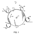
- Fig. 1 illustrates a side view of an ultrasonic system 8 comprising a rotating anvil roll 10 which rotates about a central axis 9.
- a rotating anvil roll 10 which rotates about a central axis 9.
- First base web 12 carried by a first turning roll 14
- second web 18 carried by a second turning roll 16.
- Second web 18 is received on the outer surface of the first web 12, the first web 12 being supported by the rotating anvil roll 10.
- the first and second webs 12, 18 are juxtaposed in surface-to-surface relationship with each other at turning roll 16 to form a workpiece 20 on the rotating anvil roll 10.
- the rotary ultrasonic horn 22 and rotating anvil roll 10 are positioned in close relationship to each other and define a nip 24 or small gap therebetween. As the rotating anvil roll 10 continues to rotate, the workpiece 20 passes through nip 24. After passing between the anvil roll 10 and the ultrasonic hom 22 at nip 24, the workpiece 20 leaves anvil roll 10, passing around tuming roll 26, and moves away from the workstation shown in Fig. 1, e.g. for further processing, or for packaging as a finished product.
- the first web 12 and the second web 18 can each comprise one or a plurality of flexible layers of material such as films, laminates, or fibrous webs.
- the first and second webs 12, 18 preferably comprise nonwoven and otherwise compatible thermoplastic materials which can be bonded to each other using ultrasonic energy.
- the term "compatible" defines materials, such as two layers of polypropylene or two layers of polyethylene which can be bonded to each other.
- the first and second webs 12, 18 may comprise noncompatible materials.
- both of the first and second webs 12, 18 comprise multiple layers, with each web 12, 18 having a thickness of from about 0.0025 cm (0.001 inch) to about 0.3175 cm (0.125 inch). While only two layers of material are shown forming workpiece 20, webs 12, 18 can, in combination, include up to at least six layers of material, and sometimes more layers of material.
- a suitable ultrasonic horn 22 is a rotary ultrasonic horn such as that taught in United States Patent 5,110,403 to Ehlert, which may be modified with lands and other surface characteristics as discussed hereinafter. United States Patent 5,110,403 is hereby incorporated by reference for its teaching of the general structure and general use of such a rotary ultrasonic horn 22. Alternatively, the ultrasonic horn 22 may be a stationary ultrasonic horn as are well known to those skilled in the art. If the ultrasonic horn 22 is a rotary horn, the ultrasonic horn 22 can have a diameter of about 7.62 cm (3 inches) to about 17.8 cm (7 inches) and a thickness of about 2.5 cm (1 inch) to about 10.2 cm (4 inches). The preferred diameter for the ultrasonic horn is about 15.2 cm (6 inches) and the preferred thickness is about 5.08 cm (2 inches).
- Suitable generators (not shown) to power the ultrasonic horn 22 are available from, for example, Branson Sonic Power Company, Danbury, Connecticut and others.
- the ultrasonic horn 22 includes an outer radial surface around the circumference thereof. While a rotary ultrasonic horn 22 is preferred, the invention also contemplates a nonrotary (e.g. plunge-type) ultrasonic horn as disclosed in the Background of U.S. Patent 5,110,403.
- nip pressure e.g. at nip 24
- amplitude of the horn vibration e.g. at nip 24
- time during which the ultrasonic hom 22 is acting on the workpiece 20 e.g. at nip 24
- an increase in any one of these parameters increases the amount of energy applied.
- These parameters are controlled to provide a density per unit area of from about 4.65 J/cm 2 (30 joules/square inch) to about 155 J/cm 2 (1000 joules/square inch) and desirably at least 15.50 J/cm 2 (100 joules/square inch) in the portion of the workpiece 20 being acted upon for a sufficient time period to create a changed condition.
- the portion of the workpiece 20 being acted on, of course, changes continuously as the combined continuous webs 12, 18 advance continuously to and through nip 24.
- the linear speed of the rotary ultrasonic horn 22 and the rotating anvil roll 10 at their respective outer radial surfaces are preferably the same.
- a preferred embodiment of the rotating anvil roll 10 transports the workpiece 20 at a velocity of from about 0.254 m/sec (50 feet/minute) to about 6.10 m/sec (1200 feet/minute) and desirably at least 2.54 m/sec (500 feet/minute).
- the amount of time during which ultrasonic energy is applied to the workpiece 20 at a given location preferably is about 0.0001 second to about 0.0010 second.
- the frequency of excitation of the rotary ultrasonic horn preferably is from about 18 kHz to about 60 kHz.
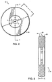
- a suitable anvil roll 10 having an outer radial surface 34.
- the cross-sectional view of Fig. 3 clearly shows a first central region 36, and second and third side regions 38 of the outer radial surface 34.
- the side regions 38 have a maximum radius less than the maximum radius in the central region 36.
- the difference "DR" between the radius at the central region 36 and the radii at the side regions 38 is (See Fig. 4A) approximately 0.025 cm (0.01 inch) to approximately 0.508 cm (0.20 inch).
- Fig. 4 is a top view of the outer radial surface 34 of the anvil roll 10 taken at 4-4 in Fig. 2, and ignoring the radius of curvature.
- This top view shows a portion of first length 40 of the outer radial surface 34 and a full second length 42 of the outer radial surface 34.
- the first length 40 includes central region 36 and opposing side regions 38.
- the second length 42 includes side regions 38, but central region 36 has been modified by the pattern of lands 44 which extend from underlying base surface 45.
- first length 40 extends around the entirety of the outer radial surface 34 between the two ends 42A, 42B of the second length 42.
- the entire circumference of the outer radial surface represented by Fig. 4 includes only a single first length 40, and a single second length 42.
- lands 44 are fabricated by cutting away material to reach base surface 45, leaving lands 44 as protrusions extending from base member 45.
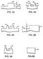
- the tops 46 of the lands 44 are positioned at substantially the same radius from the axis of rotation 9 as the central region 36 of the first length 40, as shown in the cross-sectional views of Figs. 4A and 4B.
- Fig. 4A shows a cross-section of the outer radial surface 34 along the first length 40.
- Fig. 4B shows a fragmentary cross-sectional view across the thickness at the outer radial surface 34 and is taken at 4B-4B of Fig. 4.
- Two lands 44 are shown.
- the opposing side regions 38 preferably have the same radius as an underlying base surface 45 between lands 44 as shown in Fig. 4B.
- the central region 36 has a substantially constant minor radius over at least a portion of, and preferably substantially the entirety of the outer radial surface 34 in the central region 36, except for the lands 44.
- the radius of opposing side regions 38 is also substantially constant about substantially the entire circumference of the anvil roll 10 and is the same as the minor radius in the central region 36.
- substantially the entire circumference of the anvil roll 10 can be considered a continuous outer surface having a constant radius, generally unbroken except for the pattern of lands 44 at second length 42.
- the extremities of the outer radial surface 34, namely at tops 46 of the lands 44 represent a continuity of the maximum radius of the outer radial surface 34.
- anvil roll 10 rotates and, in combination with ultrasonic horn 22, applies ultrasonic energy to the workpiece 20 without passing step-changes along the circumference of the outer radial surface 34 through the nip 24, and without effecting step-changes in the tension on the workpiece 20 because the outer radial surface 34 has a constant radius, and thus a constant diameter.
- Figs. 2-4, 4A and 4B show the first length 40 and second length 42 at the outer radial surface 34 of the anvil roll 10
- the first length 40 and second length 42 can instead, or in addition, be a part of the outer radial surface of the ultrasonic horn 22.
- Fig. 4 shows only a first length 40 and a second length 42 at the outer radial surface 34
- multiple lengths comprising lands 44 defined by the second lengths 42 can be located at the outer radial surface of either the ultrasonic horn 22 or the rotating anvil roll 10.
- Such multiple lengths 40, 42 are illustrated in Fig. 7.
- the ultrasonic system 8 works as follows.
- a first web 12 is pulled around turning roll 14 onto the outer radial surface 34 of the rotating anvil roll 10.
- a second web 18 is pulled around turning roll 16 onto the first web 12, also at outer radial surface 34.
- the webs 12, 18 comprise a series of workpieces 20 to be defined end to end therein and carried by the rotating anvil roll 10 to the rotary ultrasonic horn 22.
- the ultrasonic horn 22 and anvil roll 10 compress the workpiece 20 at nip 24 with a constant force being exerted by ultrasonic horn 22 against anvil roll 10.
- the second length 42 of the outer radial surface 34 passes through nip 24 and presses against the workpiece 20
- the second length 42 has a second amount of surface area per unit length, interactive with the ultrasonic horn 22, which corresponds to a second ultrasonic energy density per unit area of interactive surface on the rotating anvil roll 10 sufficient to activate a condition change (e.g. cutting or bonding) in the respective workpiece.
- the increased amount of surface area per unit length dissipates the ultrasonic energy being applied by ultrasonic horn 22 over a larger surface area, resulting in a lower energy density per unit area, the lower energy density being below the threshold energy density, and thus too low to cause the condition change effected at the second length 42.
- the increased energy density at length 42 allows the ultrasonic horn 22 to create a changed condition in the workpiece 20 when the second length 42 of the outer radial surface 34 is in the nip 24, without changing the pressure at the nip 24, and without a step or shock change in the pressure at the nip 24.
- the changed condition of the workpiece 20 may comprise bonding or cutting of the workpiece 20, or the like.
- Bonding describes joining or attaching two or more layers of material.
- Cutting describes forming a gap or hole through one or more layers of material, or severing e.g. a leading workpiece from a trailing workpiece.
- Figs. 5-7 and 11 show top views of other outer radial surfaces useful in this invention. These outer radial surfaces will hereinafter be described as the outer radial surface 34 of the anvil roll 10. While that location is preferred, these and related outer radial surfaces can also be utilized at the outer radial surface of the ultrasonic horn 22 and function just as effectively. Therefore, the description herein is not limited to use of the embodiments of Figs. 5-7 upon only the anvil roll 10. Corresponding use on the ultrasonic horn 22 is contemplated.
- Fig. 5 illustrates a top view of an embodiment of the invention wherein the outer radial surface 34 is free from opposing side regions 38 along the first length 40.
- the first length 40 has a first radius continuously across the surface thereof.
- the second length 42 has lands 44 cut out to form a pattern at the central region 36.
- the central region 36 has a base surface 45 which is at a second minor radius which is less than the first radius.
- the top 46 of lands 44 have a maximum radius, measured from the axis of rotation 9 substantially the same as the first radius of the first length 40. Therefore, the tops 46 of lands 44, in combination with the first length 40, provide an effectively constant maximum radius about substantially the entirety of the circumference of the outer radial surface 34.
- Fig. 5A taken at 5A-5A of Fig. 5 shows how lands 44 extend from the base surface 45.
- Fig. 5B taken at 5B-5B of Fig. 5 illustrates the difference in radius "DR" between the base surface 45 of the second length 42 and the outer radial surface 34 at its maximum radius such as at first length 40.
- the difference "DR" preferably is between approximately 0.025 cm (0.01 inch) to approximately 0.508 cm (0.20 inch).
- the embodiment of Fig. 5 functions similarly to the embodiment of Fig. 4.
- the reduced surface area caused by the narrowing of the surface along the second length 42 provides a second lesser amount of surface area per unit length of the outer radial surface 34.
- the second length 42 provides a higher ultrasonic energy density per unit area than the first length 40.
- the density per unit area of the second length 42 preferably comprises from about 4.65 J/cm 2 (30 joules/square inch) to about 155 J/cm 2 (1000 joules/square inch) and desirably at least 15.5 J/cm 2 (100 joules/square inch). Further, because Fig.
- the difference in the amount of ultrasonic energy density per unit length between the first length 40 and the second length 42 is greater. This is because of the increased surface area of the first length 40 in Fig. 5 as compared to the surface area of the first length 40 in Fig. 4.
- Fig. 6 illustrates a top view of another embodiment of the invention wherein the outer radial surface 34 comprises a relatively smaller thickness "T".
- the first length 40 has a first radius from the axis of rotation 9 extending entirely across the entire thickness "T”.
- the second length has a pattern of lands 44.
- a base surface 45 is located between the lands 44.
- the base surface 45 has a second radius from axis of rotation 9 less than the first radius.
- the width of the pattern formed by lands 44 generally corresponds with the thickness "T" of the first length 40 of the outer radial surface 34.
- Fig. 6A shows the relationship between the lands 44 and base surface 45.
- the cross-section of the overall radius of the first length 40 at the outer radial surface 34 is generally flat and preferably smooth.
- the difference in radius "DR" between the first length 40 and the base surface 45 adjacent the lands 44 comprises about 0.025cm (0.01 inch) to about 0.508cm (0.20 inch).
- the embodiment of Fig. 6 functions similarly to the embodiments of Figs. 4 and 5.
- the reduced surface area at base surface 45 provides a second lesser amount of surface area per unit length for the second length 42 of the outer radial surface 34.
- This reduced surface area per unit length increases the ultrasonic energy density per unit area to an amount great enough to change a condition (e.g. bonding, cutting) in the workpiece 20.
- the ultrasonic energy density per unit area along the first length 40 is insufficient to change the condition of the workpiece 20.
- This embodiment differs from Fig. 5 mainly to the extent that the lands 44 extend over substantially the entire second length 42.
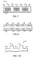
- Fig. 7 illustrates a top view of an embodiment of the invention including multiple occurrences of the second length 42 of the outer surface 34.
- a third length 50 having substantially the same radius as the first length 40 follows the second length 42.
- a fourth length 52 having substantially the same radius and pattern as the second length 42 follows the third length at the outer radial surface 34.
- a fifth length 54 having substantially the same radius as the first length 40 follows the fourth length at the outer radial surface 34.
- a sixth length 56 having substantially the same radius and pattern as the second length 42 follows the fifth length 54.
- the sixth length 56 is adjacent to the fifth length 54 and the first length 40.
- the actual measurable lengths of the first through sixth lengths may vary greatly depending upon the needs involved and the work to be performed thereby. For instance, the lengths with no pattern preferably can be much longer than the lengths containing the pattern. While three lengths with the pattern have been shown, any number of lengths having a pattern may be incorporated into an outer radial surface 34.
- Fig. 8 shows workpieces 20 after the workpieces have been operated on by ultrasonic sytem 8 of Fig. 1.
- Each workpiece 20 shows bonds 58 which represent changes in condition of the workpiece where the second length of the outer radial surface 34 of the anvil roll 10 acted on the workpiece 20.
- Bonds 60 represent parallel placement of e.g. like bonds by respective first and second ultrasonic horns 22 rotating simultaneously against a single workpiece 20 at first and second side-by-side nips such as nip 24.
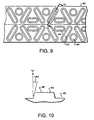
- Fig. 9 illustrates an enlarged top view of a portion of a second length 42, showing the lands 44 which form the pattern which uses ultrasonic energy to change a condition of the workpiece 20. In this view, detail of the structure of the individual lands 44 is clear.
- X-Y configuration means the pattern shown in Fig. 9. This configuration is formed by the repeating pattern of circular lands, angled long elongated lands, and short elongated lands. This configuration enhances the ability of the bonds 58, 60 to retain layers of the workpiece 20 together.
- Fig. 10 shows an elongated land 44.
- the land 44 comprises an inward angle 62 of most preferably about 15 degrees with respect to a perpendicular angle "V" as shown in Fig. 10. While an inward angle 62 of 15 degrees is most preferred, any angle 62 of between about 5 degrees and about 25 degrees will function well.
- the tapered angle 62 tend to provide additional protection for the workpiece 20 traversing the nip 24 as well as strengthening the lands 44.
- angle 62 can be as low as zero degrees, or less, and up to about 30 degrees.
- a thin band having substantially the same radius as the first length 40 can comprise the central region 36 of the second length 42 of the outer radial surface 34 as illustrated in Fig. 11.
- This embodiment of the invention utilizes a pattern with a single continuous or interconnected land 44 having a substantially constant first maximum radius at the top 46 of the land 44, the pattern extending generally uniformly about the entire circumference of the outer radial surface 34.
- the first length 40 has the pattern as defined by land 44.
- the second length 42 comprises a narrowed central region 36 having a substantially constant maximum radius in common with the maximum radius at first length 40, at top 46 of the land 44.
- the second length 42 is defined by a narrowing of the portion of thickness "T" occupied land 44, and thus by top 46.
- the portion of thickness "T" not occupied by land 44 is defined at the reduced-radius base surface 45.
- the radius of the base surface 45 is less than the maximum radius as at top 46 by approximately 0.025 cm (0.01 inch) to approximately 0.508 cm (0.20 inch).
- the radius at base surface 45 is preferably substantially constant about the circumference.
- Figure 11A shows a cross-section view of the outer radial surface 34 shown in Fig. 11.
- the second lengths 42, etc. are patterned, and the first lengths 40 etc. comprise generally unpatterned, smooth surfaces.
- a single consistent pattern extends about the entirety of the circumference of the anvil roll 10, but with a narrow application of top 46.
- both lengths 40 and 42 are patterned, and wherein the patterns are selected such that the pattern used in a length 40 has a higher surface area per unit length (at tops 46) than the pattern used in a respective length 42.
- any particular patterns used are not critical so long as they provide the requisite difference in surface area per unit length between lengths 40 and 42.
- patterns can be utilized at the outer radial surface to form e.g. bonds between a first web 12 and a second web 18.
- Lands 44 should be closely spaced with respect to each other such that at least one land 44 is present in the nip 24 at all times to maintain the constancy of the outer radial surface 34 as perceived by the webs 12, 18 against ultrasonic horn 22.
- the outer radial surface 34 Since a portion of the outer radial surface 34 has, effectively, a substantially constant radius around the entire circumference of the ultrasonic horn 22 or anvil roll 10, and no step-changes in the radius along the circumferences, there is no problem of shock loading of the material in the nip 24, the anvil roll 10, the ultrasonic horn 22, or of the bearings and other support elements supporting the ultrasonic horn 22 and anvil roll 10. Further, the substantially constant radius of the outer radial surface 34 allows for a substantially unchanging center-to-center distance and a substantially constant force at the nip 24.
Abstract
Description
- This invention relates generally to an ultrasonic system comprising an ultrasonic horn and a rotating anvil roll. Ultrasonic systems exist which bond or cut materials. The ultrasonic horn applies ultrasonic energy which effects bonding, cutting, or other change in condition of a material traversing a nip between the ultrasonic horn and rotating anvil roll.
- The present invention relates to an ultrasonic system, the ultrasonic system preferably including a rotary ultrasonic horn, and a method of using the same.
- It is known to apply ultrasonic energy to a rotary ultrasonic horn while rotating the horn against a continuously advancing workpiece. United States Patent 5,110,403 to Ehlert teaches a rotary ultrasonic horn, ostensibly for applying ultrasonic energy to a workpiece along a continuous line of engagement between the workpiece and the radial, or working, surface of the horn.
- Application Serial No. 08/381,363, attorney docket No. 11,460, filed January 31, 1995, in the names of Rajala et al. and of common assignment herewith, teaches a protuberance extending from the outer working surface of the ultrasonic horn, or the anvil, for applying ultrasonic energy to one or more workpieces at spaced locations.
- The art is devoid of apparatus and methods for effecting intermittent or spaced application of ultrasonic energy to one or more workpieces without utilizing a protuberance on the ultrasonic horn or the anvil.
- It is an object of the invention to provide a method for processing a workpiece using ultrasonic energy to provide an intermittent change of a condition of the workpiece while maintaining constant the radius of the outer radial surface, free from protuberances.
- It is another object to provide an ultrasonic system, including a rotating anvil roll having a first length with a first amount of surface area per unit length at the working outer radial surface and a second length with a lesser amount of surface area per unit length at the working outer radial surface, such that a condition of a workpiece is changed as the workpiece passes through a nip between the rotating anvil roll and the ultrasonic horn.
- It is yet another object to provide first and second lengths of an outer radial surface of one of the rotating anvil roll and ultrasonic horn, with lands forming a pattern at the respective outer radial surface, such that the lands have a reduced surface area per unit length whereby the ultrasonic energy generated by the ultrasonic horn changes a condition of a workpiece passing through the nip between the rotating anvil roll and ultrasonic horn.
- It is still another object to provide the lands as an "X-Y" pattern at the outer radial surface, the lands preferably extending from an underlying base surface at an inwardly sloped angle of between about 5 degrees and about 25 degrees with respect to a perpendicular angle to the base surface.
- It is a further object to provide an ultrasonic horn and rotating anvil roll which intermittently bond, cut, or otherwise change, with ultrasonic energy, a condition of a material passing therebetween, while maintaining the workpiece substantially free from changes in tension caused by surface characteristics of the rotating anvil roll or the ultrasonic horn.
- This invention relates to ultrasonic systems and methods for intermittently changing a condition in a workpiece. The system includes an anvil roll and an ultrasonic horn which change the condition in the workpiece. One of the anvil roll and the ultrasonic horn has a substantially constant radius along a first length, and a second length having substantially the same radius as the first length, but a reduced surface area. The reduced surface area allows for a higher ultrasonic energy density per unit area along the second length which changes the condition of the workpiece.
- In one aspect, the present invention resides in an ultrasonic system comprising an ultrasonic horn, outputting ultrasonic energy; and a rotating anvil roll having an outer radial surface extending along at least a substantial portion of a circumference, the rotating anvil roll receiving a workpiece to be worked by ultrasonic energy, and cooperating with the ultrasonic horn to form a close relationship comprising a nip between the ultrasonic horn and the rotating anvil roll for passage of the workpiece therethrough, the outer radial surface of the rotating anvil roll having a first length thereof defining a first amount of surface area per unit length, interactive with the ultrasonic horn, corresponding to a first ultrasonic energy density per unit area of interactive surface on the rotating anvil roll, and a second separate and distinct length of the outer radial surface defining a second lesser amount of surface area per unit length of the outer radial surface, interactive with the ultrasonic horn, corresponding to a second higher ultrasonic energy density per unit area of interactive surface on the rotating anvil roll, ultrasonic energy being applied to the workpiece in the nip, such that when the second length of the rotating anvil roll is in the nip, the ultrasonic energy changes a condition in the workpiece, and when the first length of the rotating anvil roll is in the nip, the ultrasonic energy does not change the same condition in the workpiece.
- In one embodiment the outer radial surface has a substantially constant radius extending substantially around the circumference. A first portion of the first length and a second portion of the second length can maintain constant first and second radii around the circumference.
- In another aspect of the invention the workpiece traverses the ultrasonic system substantially free from changes in tension caused by surface characteristics of any one of the ultrasonic horn and the rotating anvil roll.
- The second length includes a pattern of lands extending from an underlying base surface. In one embodiment the pattern comprises an X-Y pattern. The lands preferably extend outwardly from a base surface by approximately 0.025 cm (0.01 inch) to approximately 0.508 cm (0.20 inch). The lands generally extend from the base surface at an inwardly sloping angle of between about 5 degrees and about 25 degrees, preferably about 15 degrees, with respect to a perpendicular angle to the base surface.
- In one embodiment the outer radial surface of the rotating anvil roll includes a first central region having a first constant maximum radius about the circumference thereof, the outer radial surface including the first length and the second length, and second and third side regions disposed on opposing sides of the first central region, the second and third side regions having respective second and third maximum radii less than the first maximum radius of the first central region. The second and third radii are generally smaller than the first maximum radius by approximately 0.025 cm (0.01 inch) to approximately 0.508 cm (0.20 inch).
- In another embodiment, the entirety of the first length of the outer radial surface of the rotating anvil roll comprehends a generally uniform surface characteristic at a first maximum radius thereof, having a first effective width, the second length of the outer radial surface having the same generally uniform surface characteristic at a second maximum radius thereof, and a second narrower width, and thus defining the second lesser amount of surface area per unit length of the outer radial surface.
- In some embodiments the changed condition comprises bonding together at least two layers of material in the workpiece. In other embodiments, the changed condition can also comprise cutting.
- In preferred embodiments at least one of the layers being bonded or cut can comprise polypropylene.
- In another aspect of the invention, the rotating anvil roll transports the workpiece through the nip at a speed of from about 0.254 m/sec (50 feet/minute) to about 6.10 m/sec (1200 feet/minute). The ultrasonic system can preferably generate from about 4.65 joules/ square cm (J/cm2) (30 joules/square inch) to about 155 J/cm2 (1000 joules/square inch) of energy along the second length of the outer radial surface. The workpiece can be transported through the nip at a speed such that the ultrasonic energy is applied at a given location on the workpiece for a period of about 0.0001 second to about 0.0010 second. The rotary ultrasonic horn and the rotating anvil roll can rotate at a common linear speed at respective outer radial surfaces thereof.
- In some embodiments, the ultrasonic horn comprises a rotary ultrasonic horn. The rotary ultrasonic horn and the rotating anvil roll, in combination, can apply a compressive force to the workpiece in the nip. The rotary ultrasonic horn has a diameter of about 7.62cm (3 inches) to about 17.8cm (7 inches) and a thickness of about 2.54cm (1 inch) to about 10.2cm (4 inches). The ultrasonic energy normally produced by the ultrasonic system cannot create a changed condition in the workpiece in the nip when the first length of the outer radial surface of the rotating anvil roll is in the nip.
- In another embodiment of the invention, the outer radial surface of the rotating anvil roll has a third length thereof defining a third amount of surface area per unit length greater than the surface area per unit length of the second length, and a fourth length thereof defining a fourth amount of surface area per unit length substantially equal to the surface area per unit length of the second length, the first, second, third and fourth lengths being arranged in sequential order about the outer radial surface of the rotating anvil roll.
- In another embodiment the lands extend from substantially all areas of the outer radial surface of the second length.
- In yet another embodiment the lands are confined within a central region of the outer radial surface of the second length.
- The invention further comprehends an ultrasonic system comprising a rotary ultrasonic hom outputting ultrasonic energy, the horn having a first axis of rotation, and a first circumference defining a first outer radial surface; and a rotating anvil roll having a second axis of rotation and a second circumference defining a second outer radial surface, the rotating anvil roll cooperating with the rotary ultrasonic horn to form a close relationship comprising a nip between the rotary ultrasonic horn and the rotating anvil roll, one of the first and second outer radial surfaces having a first length thereof defining a first amount of
surface area per unit length, interactive with the other of the first and second outer radial surfaces, and corresponding to a first ultrasonic energy density per unit area of interactive surface, and a second separate and distinct length of the respective outer radial surface defining a second lesser amount of surface area per unit length of the respective outer radial surface, interactive with the other of the first and second outer radial surfaces, and corresponding to a second higher ultrasonic energy density per unit area of interactive surface, whereby when ultrasonic energy is applied to the workpiece in the nip, and the second length passes into the nip, the ultrasonic energy can create a changed condition in the workpiece, and when the first length passes into the nip, the ultrasonic energy cannot create the same changed condition in the workpiece. - In another embodiment the first outer radial surface has a substantially constant first maximum radius extending substantially around the first circumference, and the second outer radial surface has a substantially constant second maximum radius extending substantially around the second circumference.
- In another embodiment at least a first portion of the first length and a second portion of the second length maintain constant first and second maximum radii around the circumference.
- In another embodiment one of the first and second outer radial surfaces having the first length and the second length includes a first central region having a first constant maximum radius about the respective one of the first and second circumferences, the one of the first and second outer radial surfaces including second and third side regions disposed on opposing sides of the first central region, the second and third side regions having respective second and third maximum radii less than the first maximum radius of the first central region.
The second and third maximum radii are smaller than the first maximum radius by approximately 0.025 cm (0.01 inch) to approximately 0.508 cm (0.20 inch). - In another embodiment, the second and third side regions, including the second and third maximum radii, extend around substantially the entirety of the circumference of the one of the first and second outer radial surfaces.
- In yet another embodiment, substantially the entirety of the first length of the respective the outer radial surface comprehends a generally uniform surface characteristic at a first maximum radius thereof, having a first effective width, the second length of the respective outer radial surface having the same generally uniform surface characteristic at a second maximum radius thereof, and a second narrower width, and thus defining the second lesser amount of surface area per unit length of the respective outer radial surface.
- The invention further comprehends a method of intermittently changing a condition in a workpiece while exerting a substantially constant force between a rotary ultrasonic horn and a rotating anvil roll, the method comprising the steps of positioning a rotary ultrasonic horn in close relationship with a rotating anvil roll and thereby defining a working nip between the rotary ultrasonic horn and the rotating anvil roll, the rotary ultrasonic horn having a first outer radial surface extending about a first circumference, the rotating anvil roll having a second outer radial surface extending about a second circumference, one of the first and second outer radial surfaces having a first length thereof defining a first amount of surface area per unit length, interactive with the other of the first and second outer radial surfaces, and a second separate and distinct length defining a second lesser amount of surface area per unit length, interactive with the other of the first and second outer radial surfaces, corresponding to a second higher ultrasonic energy density per unit area of interactive surface; and advancing a workpiece through the working nip at a relatively constant speed while applying ultrasonic energy at the rotary ultrasonic horn and advancing the first and second lengths of the respective outer radial surface through the nip, thereby changing a condition of the workpiece with ultrasonic energy as the second length passes through the nip, and not changing the respective condition of the workpiece as the first length passes through the nip.
-
- Fig. 1 shows a side view of processing apparatus including apparatus of the invention.
- Fig. 2 shows a side view of an anvil roll of the invention.
- Fig. 3 shows a cross-sectional view of the anvil roll taken at 3-3 in Fig. 2.
- Fig. 4 shows a top view of an outer radial surface of the anvil roll taken at 4-4 in Fig. 2, ignoring the radius of curvature.
- Fig. 4A shows a cross-sectional view of the outer radial surface taken at 4A-4A in Fig. 4.
- Fig. 4B shows a cross-sectional view of the outer radial surface taken at 4B-4B in Fig. 4.
- Fig. 5 shows a top view of a second embodiment of an outer radial surface of either a rotary ultrasonic horn or a rotating anvil roll, ignoring the radius of curvature.
- Fig. 5A shows a cross-sectional view of the outer radial surface taken at 5A-5A in Fig. 5.
- Fig. 5B shows a cross-sectional view of the outer radial surface taken at 5B-5B in Fig. 5.
- Fig. 6 shows a top view of a third embodiment of an outer radial surface of either a rotary ultrasonic horn or a rotating anvil roll, ignoring the radius of curvature.
- Fig. 6A shows a cross-sectional view of the outer radial surface taken at 6A-6A in Fig. 6.
- Fig. 6B shows a cross-sectional view of the outer radial surface taken at 6B-6B in Fig. 6.
- Fig. 7 shows a top view of a fourth embodiment of an outer radial surface of either a rotary ultrasonic horn or a rotating anvil roll, ignoring the radius of curvature.
- Fig. 8 shows a top view of a workpiece after having been operated on by the apparatus of Fig. 1.
- Fig. 9 shows a close-up top view of the lands which form a pattern on an outer radial surface of a rotary ultrasonic horn or a rotating anvil roll.
- Fig. 10 shows a cross-sectional view of a land taken at 10-10 in Fig. 9.
- Fig. 11 shows a top view of a fifth embodiment of an outer radial surface of either a rotary ultrasonic horn or a rotating anvil roll, ignoring the radius of curvature.
- Fig. 11A shows a cross-sectional view of an outer radial surface taken at 11A-11A of Fig. 11.
-
- The invention is not limited in its application to the details of construction and the arrangement of the components set forth in the following description or illustrated in the drawings. The invention is capable of other embodiments or of being practiced or carried out in various ways. Also, it is to be understood that the terminology and phraseology employed herein is for purpose of description and illustration and should not be regarded as limiting. Like reference numerals are used to indicate like components.
- The present invention describes apparatus and methods for applying ultrasonic energy to a workpiece, and thereby intermittently effecting a changed condition in the workpiece. This invention is generally utilized in the manufacture of absorbent articles such as diapers, feminine hygiene products or the like.
- The present invention can best be understood by reference to the drawings. Fig. 1 illustrates a side view of an ultrasonic system 8 comprising a
rotating anvil roll 10 which rotates about acentral axis 9. As the anvil roll rotates, it receives a first base web 12 carried by afirst turning roll 14, and asecond web 18 carried by asecond turning roll 16.Second web 18 is received on the outer surface of the first web 12, the first web 12 being supported by the rotatinganvil roll 10. The first andsecond webs 12, 18 are juxtaposed in surface-to-surface relationship with each other at turningroll 16 to form aworkpiece 20 on therotating anvil roll 10. The rotaryultrasonic horn 22 androtating anvil roll 10 are positioned in close relationship to each other and define a nip 24 or small gap therebetween. As therotating anvil roll 10 continues to rotate, the workpiece 20 passes through nip 24. After passing between theanvil roll 10 and theultrasonic hom 22 at nip 24, theworkpiece 20 leavesanvil roll 10, passing aroundtuming roll 26, and moves away from the workstation shown in Fig. 1, e.g. for further processing, or for packaging as a finished product. - The first web 12 and the
second web 18 can each comprise one or a plurality of flexible layers of material such as films, laminates, or fibrous webs. The first andsecond webs 12, 18 preferably comprise nonwoven and otherwise compatible thermoplastic materials which can be bonded to each other using ultrasonic energy. The term "compatible" defines materials, such as two layers of polypropylene or two layers of polyethylene which can be bonded to each other. Alternatively, the first andsecond webs 12, 18 may comprise noncompatible materials. Typically, both of the first andsecond webs 12, 18 comprise multiple layers, with eachweb 12, 18 having a thickness of from about 0.0025 cm (0.001 inch) to about 0.3175 cm (0.125 inch). While only two layers of material are shown formingworkpiece 20,webs 12, 18 can, in combination, include up to at least six layers of material, and sometimes more layers of material. - A suitable
ultrasonic horn 22 is a rotary ultrasonic horn such as that taught in United States Patent 5,110,403 to Ehlert, which may be modified with lands and other surface characteristics as discussed hereinafter. United States Patent 5,110,403 is hereby incorporated by reference for its teaching of the general structure and general use of such a rotaryultrasonic horn 22. Alternatively, theultrasonic horn 22 may be a stationary ultrasonic horn as are well known to those skilled in the art. If theultrasonic horn 22 is a rotary horn, theultrasonic horn 22 can have a diameter of about 7.62 cm (3 inches) to about 17.8 cm (7 inches) and a thickness of about 2.5 cm (1 inch) to about 10.2 cm (4 inches). The preferred diameter for the ultrasonic horn is about 15.2 cm (6 inches) and the preferred thickness is about 5.08 cm (2 inches). - Suitable generators (not shown) to power the
ultrasonic horn 22 are available from, for example, Branson Sonic Power Company, Danbury, Connecticut and others. Theultrasonic horn 22 includes an outer radial surface around the circumference thereof. While a rotaryultrasonic horn 22 is preferred, the invention also contemplates a nonrotary (e.g. plunge-type) ultrasonic horn as disclosed in the Background of U.S. Patent 5,110,403. - To control the amount of ultrasonic energy applied by the
ultrasonic horn 22, one generally controls combined parameters of nip pressure, e.g. at nip 24, amplitude of the horn vibration, and the time during which theultrasonic hom 22 is acting on theworkpiece 20. Within the combined operating ranges of the several parameters, an increase in any one of these parameters increases the amount of energy applied. These parameters are controlled to provide a density per unit area of from about 4.65 J/cm2 (30 joules/square inch) to about 155 J/cm2 (1000 joules/square inch) and desirably at least 15.50 J/cm2 (100 joules/square inch) in the portion of theworkpiece 20 being acted upon for a sufficient time period to create a changed condition. The portion of theworkpiece 20 being acted on, of course, changes continuously as the combinedcontinuous webs 12, 18 advance continuously to and through nip 24. - It is contemplated that the linear speed of the rotary
ultrasonic horn 22 and therotating anvil roll 10 at their respective outer radial surfaces, are preferably the same. A preferred embodiment of therotating anvil roll 10 transports theworkpiece 20 at a velocity of from about 0.254 m/sec (50 feet/minute) to about 6.10 m/sec (1200 feet/minute) and desirably at least 2.54 m/sec (500 feet/minute). The amount of time during which ultrasonic energy is applied to theworkpiece 20 at a given location preferably is about 0.0001 second to about 0.0010 second. The frequency of excitation of the rotary ultrasonic horn preferably is from about 18 kHz to about 60 kHz. - Referring now to Figs. 2 and 3, a
suitable anvil roll 10 is shown having an outerradial surface 34. The cross-sectional view of Fig. 3 clearly shows a firstcentral region 36, and second andthird side regions 38 of the outerradial surface 34. Theside regions 38 have a maximum radius less than the maximum radius in thecentral region 36. The difference "DR" between the radius at thecentral region 36 and the radii at theside regions 38 is (See Fig. 4A) approximately 0.025 cm (0.01 inch) to approximately 0.508 cm (0.20 inch). - Fig. 4 is a top view of the outer
radial surface 34 of theanvil roll 10 taken at 4-4 in Fig. 2, and ignoring the radius of curvature. This top view shows a portion offirst length 40 of the outerradial surface 34 and a fullsecond length 42 of the outerradial surface 34. Thefirst length 40 includescentral region 36 and opposingside regions 38. Thesecond length 42 includesside regions 38, butcentral region 36 has been modified by the pattern oflands 44 which extend fromunderlying base surface 45. As suggested in Fig. 4,first length 40 extends around the entirety of the outerradial surface 34 between the twoends second length 42. Thus, the entire circumference of the outer radial surface represented by Fig. 4 includes only a singlefirst length 40, and a singlesecond length 42. - Those skilled in the art will recognize that the pattern of
lands 44 is fabricated by cutting away material to reachbase surface 45, leavinglands 44 as protrusions extending frombase member 45. - The tops 46 of the
lands 44 are positioned at substantially the same radius from the axis ofrotation 9 as thecentral region 36 of thefirst length 40, as shown in the cross-sectional views of Figs. 4A and 4B. Fig. 4A shows a cross-section of the outerradial surface 34 along thefirst length 40. Fig. 4B shows a fragmentary cross-sectional view across the thickness at the outerradial surface 34 and is taken at 4B-4B of Fig. 4. Twolands 44 are shown. The opposingside regions 38 preferably have the same radius as anunderlying base surface 45 betweenlands 44 as shown in Fig. 4B. Therefore, thecentral region 36 has a substantially constant minor radius over at least a portion of, and preferably substantially the entirety of the outerradial surface 34 in thecentral region 36, except for thelands 44. The radius of opposingside regions 38 is also substantially constant about substantially the entire circumference of theanvil roll 10 and is the same as the minor radius in thecentral region 36. For these reasons, substantially the entire circumference of theanvil roll 10 can be considered a continuous outer surface having a constant radius, generally unbroken except for the pattern oflands 44 atsecond length 42. And even insecond length 42, the extremities of the outerradial surface 34, namely at tops 46 of thelands 44 represent a continuity of the maximum radius of the outerradial surface 34. Thus,anvil roll 10 rotates and, in combination withultrasonic horn 22, applies ultrasonic energy to theworkpiece 20 without passing step-changes along the circumference of the outerradial surface 34 through thenip 24, and without effecting step-changes in the tension on theworkpiece 20 because the outerradial surface 34 has a constant radius, and thus a constant diameter. - While the embodiments of Figs. 2-4, 4A and 4B show the
first length 40 andsecond length 42 at the outerradial surface 34 of theanvil roll 10, thefirst length 40 andsecond length 42 can instead, or in addition, be a part of the outer radial surface of theultrasonic horn 22. While Fig. 4 shows only afirst length 40 and asecond length 42 at the outerradial surface 34, multiplelengths comprising lands 44 defined by thesecond lengths 42 can be located at the outer radial surface of either theultrasonic horn 22 or therotating anvil roll 10. Suchmultiple lengths - In operation, the ultrasonic system 8 works as follows. A first web 12 is pulled around turning
roll 14 onto the outerradial surface 34 of therotating anvil roll 10. Asecond web 18 is pulled around turningroll 16 onto the first web 12, also at outerradial surface 34. Thewebs 12, 18 comprise a series ofworkpieces 20 to be defined end to end therein and carried by the rotatinganvil roll 10 to the rotaryultrasonic horn 22. The rotaryultrasonic horn 22 and therotating anvil roll 10, in combination, rotate in a common line of advance as shown by the arrows ofrotation ultrasonic horn 22 andanvil roll 10, respectively. Correspondingly, theultrasonic horn 22 andanvil roll 10 compress theworkpiece 20 at nip 24 with a constant force being exerted byultrasonic horn 22 againstanvil roll 10. When thesecond length 42 of the outerradial surface 34 passes through nip 24 and presses against theworkpiece 20, thesecond length 42 has a second amount of surface area per unit length, interactive with theultrasonic horn 22, which corresponds to a second ultrasonic energy density per unit area of interactive surface on therotating anvil roll 10 sufficient to activate a condition change (e.g. cutting or bonding) in the respective workpiece. When thefirst length 40 of the outerradial surface 34 rotates into nip 24 and is against theworkpiece 20, the increased amount of surface area per unit length dissipates the ultrasonic energy being applied byultrasonic horn 22 over a larger surface area, resulting in a lower energy density per unit area, the lower energy density being below the threshold energy density, and thus too low to cause the condition change effected at thesecond length 42. Thus, the increased energy density atlength 42 allows theultrasonic horn 22 to create a changed condition in theworkpiece 20 when thesecond length 42 of the outerradial surface 34 is in thenip 24, without changing the pressure at thenip 24, and without a step or shock change in the pressure at thenip 24. - The changed condition of the
workpiece 20 may comprise bonding or cutting of theworkpiece 20, or the like. Bonding describes joining or attaching two or more layers of material. Cutting describes forming a gap or hole through one or more layers of material, or severing e.g. a leading workpiece from a trailing workpiece. - Figs. 5-7 and 11 show top views of other outer radial surfaces useful in this invention. These outer radial surfaces will hereinafter be described as the outer
radial surface 34 of theanvil roll 10. While that location is preferred, these and related outer radial surfaces can also be utilized at the outer radial surface of theultrasonic horn 22 and function just as effectively. Therefore, the description herein is not limited to use of the embodiments of Figs. 5-7 upon only theanvil roll 10. Corresponding use on theultrasonic horn 22 is contemplated. - Fig. 5 illustrates a top view of an embodiment of the invention wherein the outer
radial surface 34 is free from opposingside regions 38 along thefirst length 40. Thefirst length 40 has a first radius continuously across the surface thereof. Thesecond length 42 haslands 44 cut out to form a pattern at thecentral region 36. Thecentral region 36 has abase surface 45 which is at a second minor radius which is less than the first radius. The top 46 oflands 44 have a maximum radius, measured from the axis ofrotation 9 substantially the same as the first radius of thefirst length 40. Therefore, the tops 46 oflands 44, in combination with thefirst length 40, provide an effectively constant maximum radius about substantially the entirety of the circumference of the outerradial surface 34. Fig. 5A taken at 5A-5A of Fig. 5 shows how lands 44 extend from thebase surface 45. Fig. 5B taken at 5B-5B of Fig. 5 illustrates the difference in radius "DR" between thebase surface 45 of thesecond length 42 and the outerradial surface 34 at its maximum radius such as atfirst length 40. The difference "DR" preferably is between approximately 0.025 cm (0.01 inch) to approximately 0.508 cm (0.20 inch). - The embodiment of Fig. 5 functions similarly to the embodiment of Fig. 4. The reduced surface area caused by the narrowing of the surface along the
second length 42 provides a second lesser amount of surface area per unit length of the outerradial surface 34. In this manner, thesecond length 42 provides a higher ultrasonic energy density per unit area than thefirst length 40. The density per unit area of thesecond length 42 preferably comprises from about 4.65 J/cm2 (30 joules/square inch) to about 155 J/cm2 (1000 joules/square inch) and desirably at least 15.5 J/cm2 (100 joules/square inch). Further, because Fig. 5 does not have the reduced-radius side portions 38 infirst length 40, the difference in the amount of ultrasonic energy density per unit length between thefirst length 40 and thesecond length 42 is greater. This is because of the increased surface area of thefirst length 40 in Fig. 5 as compared to the surface area of thefirst length 40 in Fig. 4. - Fig. 6 illustrates a top view of another embodiment of the invention wherein the outer
radial surface 34 comprises a relatively smaller thickness "T". Thefirst length 40 has a first radius from the axis ofrotation 9 extending entirely across the entire thickness "T". The second length has a pattern of lands 44. Abase surface 45 is located between thelands 44. Thebase surface 45 has a second radius from axis ofrotation 9 less than the first radius. The width of the pattern formed bylands 44 generally corresponds with the thickness "T" of thefirst length 40 of the outerradial surface 34. Fig. 6A shows the relationship between thelands 44 andbase surface 45. The cross-section of the overall radius of thefirst length 40 at the outerradial surface 34 is generally flat and preferably smooth. The difference in radius "DR" between thefirst length 40 and thebase surface 45 adjacent thelands 44 comprises about 0.025cm (0.01 inch) to about 0.508cm (0.20 inch). - The embodiment of Fig. 6 functions similarly to the embodiments of Figs. 4 and 5. The reduced surface area at
base surface 45 provides a second lesser amount of surface area per unit length for thesecond length 42 of the outerradial surface 34. This reduced surface area per unit length increases the ultrasonic energy density per unit area to an amount great enough to change a condition (e.g. bonding, cutting) in theworkpiece 20. The ultrasonic energy density per unit area along thefirst length 40 is insufficient to change the condition of theworkpiece 20. This embodiment differs from Fig. 5 mainly to the extent that thelands 44 extend over substantially the entiresecond length 42. - Fig. 7 illustrates a top view of an embodiment of the invention including multiple occurrences of the
second length 42 of theouter surface 34. A third length 50 having substantially the same radius as thefirst length 40 follows thesecond length 42. A fourth length 52 having substantially the same radius and pattern as thesecond length 42 follows the third length at the outerradial surface 34. A fifth length 54 having substantially the same radius as thefirst length 40 follows the fourth length at the outerradial surface 34. A sixth length 56 having substantially the same radius and pattern as thesecond length 42 follows the fifth length 54. The sixth length 56 is adjacent to the fifth length 54 and thefirst length 40. These lengths or patterns comprise an ultrasonic system 8 which performs multiple changes upon aworkpiece 20 during each rotation thereof. - The actual measurable lengths of the first through sixth lengths may vary greatly depending upon the needs involved and the work to be performed thereby. For instance, the lengths with no pattern preferably can be much longer than the lengths containing the pattern. While three lengths with the pattern have been shown, any number of lengths having a pattern may be incorporated into an outer
radial surface 34. - Fig. 8 shows
workpieces 20 after the workpieces have been operated on by ultrasonic sytem 8 of Fig. 1. Eachworkpiece 20 showsbonds 58 which represent changes in condition of the workpiece where the second length of the outerradial surface 34 of theanvil roll 10 acted on theworkpiece 20.Bonds 60 represent parallel placement of e.g. like bonds by respective first and secondultrasonic horns 22 rotating simultaneously against asingle workpiece 20 at first and second side-by-side nips such as nip 24. - Fig. 9 illustrates an enlarged top view of a portion of a
second length 42, showing thelands 44 which form the pattern which uses ultrasonic energy to change a condition of theworkpiece 20. In this view, detail of the structure of theindividual lands 44 is clear. - As used herein, the term "X-Y configuration" means the pattern shown in Fig. 9. This configuration is formed by the repeating pattern of circular lands, angled long elongated lands, and short elongated lands. This configuration enhances the ability of the
bonds workpiece 20 together. - Fig. 10 shows an
elongated land 44. Theland 44 comprises aninward angle 62 of most preferably about 15 degrees with respect to a perpendicular angle "V" as shown in Fig. 10. While aninward angle 62 of 15 degrees is most preferred, anyangle 62 of between about 5 degrees and about 25 degrees will function well. The taperedangle 62 tend to provide additional protection for theworkpiece 20 traversing thenip 24 as well as strengthening thelands 44. Thusangle 62 can be as low as zero degrees, or less, and up to about 30 degrees. - While the specific X-Y pattern created by the
lands 44 is shown in all of the embodiments, applicant's invention is not limited to this pattern. For instance, a thin band having substantially the same radius as thefirst length 40 can comprise thecentral region 36 of thesecond length 42 of the outerradial surface 34 as illustrated in Fig. 11. This embodiment of the invention utilizes a pattern with a single continuous orinterconnected land 44 having a substantially constant first maximum radius at the top 46 of theland 44, the pattern extending generally uniformly about the entire circumference of the outerradial surface 34. Thus, thefirst length 40 has the pattern as defined byland 44. Thesecond length 42 comprises a narrowedcentral region 36 having a substantially constant maximum radius in common with the maximum radius atfirst length 40, attop 46 of theland 44. Thesecond length 42 is defined by a narrowing of the portion of thickness "T" occupiedland 44, and thus by top 46. The portion of thickness "T" not occupied byland 44 is defined at the reduced-radius base surface 45. The radius of thebase surface 45 is less than the maximum radius as at top 46 by approximately 0.025 cm (0.01 inch) to approximately 0.508 cm (0.20 inch). The radius atbase surface 45 is preferably substantially constant about the circumference. - Figure 11A shows a cross-section view of the outer
radial surface 34 shown in Fig. 11. - In the embodiments of Figs. 4-7 above, the
second lengths 42, etc. are patterned, and thefirst lengths 40 etc. comprise generally unpatterned, smooth surfaces. In Fig. 11, a single consistent pattern extends about the entirety of the circumference of theanvil roll 10, but with a narrow application oftop 46. Further embodiments are contemplated wherein bothlengths length 40 has a higher surface area per unit length (at tops 46) than the pattern used in arespective length 42. - The particular designs and layouts of any particular patterns used are not critical so long as they provide the requisite difference in surface area per unit length between
lengths second web 18. -
Lands 44 should be closely spaced with respect to each other such that at least oneland 44 is present in thenip 24 at all times to maintain the constancy of the outerradial surface 34 as perceived by thewebs 12, 18 againstultrasonic horn 22. - Since a portion of the outer
radial surface 34 has, effectively, a substantially constant radius around the entire circumference of theultrasonic horn 22 oranvil roll 10, and no step-changes in the radius along the circumferences, there is no problem of shock loading of the material in thenip 24, theanvil roll 10, theultrasonic horn 22, or of the bearings and other support elements supporting theultrasonic horn 22 andanvil roll 10. Further, the substantially constant radius of the outerradial surface 34 allows for a substantially unchanging center-to-center distance and a substantially constant force at thenip 24. - Those skilled in the art will now see that certain modifications can be made to the invention herein disclosed with respect to the illustrated embodiments, without departing from the scope of the instant invention. And while the invention has been described above with respect to the preferred embodiments, it will be understood that the invention is adapted to numerous rearrangements, modifications, and alterations, and all such arrangements, modifications, and alterations are intended to be within the scope of the appended claims.
Claims (60)
- An ultrasonic system (8), comprising(a) an ultrasonic horn (22), outputting ultrasonic energy; and(b) a rotating anvil roll (10) having an outer radial surface (34) extending along at least a substantial portion of a circumference, said rotating anvil roll (10) receiving a workpiece (20) to be worked by ultrasonic energy, and cooperating with said ultrasonic horn (22) to form a close relationship comprising a nip (24) between said ultrasonic horn (22) and said rotating anvil roll (10) for passage of the workpiece (20) therethrough, characterised in that;
said outer radial surface (34) of said rotating anvil roll (10) having a first length (40) thereof defining a first amount of surface area per unit length, interactive with said ultrasonic hom (22), corresponding to a first ultrasonic energy density per unit area of interactive surface on said rotating anvil roll (10), and a second separate and distinct length (42) of said outer radial surface (34) defining a second lesser amount of surface area per unit length of said outer radial surface (34), interactive with said ultrasonic horn (22), corresponding to a second higher ultrasonic energy density per unit area of interactive surface on said rotating anvil roll (10), ultrasonic energy being applied to the workpiece (20) in the nip (24), such that when said second length (42) of said rotating anvil roll (10) is in the nip (24), the ultrasonic energy changes a condition in the workpiece (20), and when said first length (40) of said rotating anvil roll (10) is in the nip (24), the ultrasonic energy does not change the same condition in the workpiece (20). - An ultrasonic system (8) of claim 1 wherein said outer radial surface (34) has a substantially constant radius extending substantially around the circumference
- An ultrasonic system (8) of claim 1 or 2, wherein at least a first portion of said first length (40) and a second portion of said second length (42) maintain constant first and second radii around the circumference.
- An ultrasonic system (8) of any one of claims 1 to 3, wherein said second length (42) of said outer radial surface (34) comprises a pattern of lands (44) extending from an underlying base surface (45).
- An ultrasonic system (8) of claim 4, wherein said lands (44) extend from substantially all areas of said outer radial surface (34) of said second length (42).
- An ultrasonic system (8) of claim 4, wherein said lands (44) are confined within a central region (36) of said outer radial surface (34) of said second length (42).
- An ultrasonic system (8) of any one of claims 1 to 6, wherein said outer radial surface (34) of said rotating anvil roll (10) includes a first central region (36) having a first constant maximum radius about the circumference thereof, said outer radial surface (34) including said first length (40) and said second length (42), and second and third side regions (38) disposed on opposing sides of said first central region (36), said second and third side regions (38) having respective second and third maximum radii less than the first maximum radius of said first central region (36).
- An ultrasonic system (8) of claim 7, wherein said second and third radii are smaller than said first maximum radius by approximately 0.025 cm (0.01 inch) to approximately 0.508 cm (0.20 inch).
- An ultrasonic system (8) of any one of claims 1 to 8,
wherein substantially the entirety of said first length (40) of said outer radial surface (34) of said rotating anvil roll (10) comprehends a generally uniform surface characteristic at a first maximum radius thereof, having a first effective width, said second length of said outer radial surface having the same generally uniform surface characteristic at a second maximum radius thereof, and a second narrower width, and thus defining said second lesser amount of surface area per unit length of said outer radial surface (34). - An ultrasonic system (8) of any one of claims 1 to 9, wherein said ultrasonic horn (22) comprises a rotary ultrasonic horn (22), and wherein said rotary ultrasonic horn (22) and said rotating anvil roll (10), in combination, apply a compressive force to the workpiece (20) in the nip (24).
- An ultrasonic system (8) of any one of claims 1 to 10, wherein the ultrasonic energy normally produced by said ultrasonic system (8) cannot create the changed condition in the workpiece (20) in the nip (24) when said first length (40) of said outer radial surface (34) of said rotating anvil roll (10) is in the nip (24).
- An ultrasonic system (8) of any one of claims 1 to 11, said outer radial surface (34) of said rotating anvil roll (10) having a third length (50) thereof defining a third amount of surface area per unit length greater than the surface area per unit length of said second length (42), and a fourth length (52) thereof defining a fourth amount of surface area per unit length substantially equal to the surface area per unit length of said second length (42), said first (40), second (42), third (50) and fourth (52) lengths being arranged in sequential order about said outer radial surface (34) of said rotating anvil roll (10).
- An ultrasonic system (8), comprising:characterised in that one of said first and second outer radial surfaces (34) having a first length (40) thereof defines a first amount of surface area per unit length, interactive with the other of said first and second outer radial surfaces (34), and corresponding to a first ultrasonic energy density per unit area of interactive surface, and a second separate and distinct length (42) of the respective said outer radial surface defines a second lesser amount of surface area per unit length of the respective said outer radial surface, interactive with the other of said first and second outer radial surfaces (34), and corresponding to a second higher ultrasonic energy density per unit area of interactive surface, whereby when ultrasonic energy is applied to the workpiece (20) in the nip (24), and the second length (42) passes into the nip (24), the ultrasonic energy can create a changed condition in the workpiece (20), and when the first length (40) passes into the nip (24), the ultrasonic energy cannot create the same changed condition in the workpiece (20).(a) a rotary ultrasonic horn (22), said rotary ultrasonic horn (22) outputting ultrasonic energy, said horn (22) having a first axis of rotation, and a first circumference defining a first outer radial surface; and(b) a rotating anvil roll (10) having a second axis of rotation (9) and a second circumference defining a second outer radial surface (34), said rotating anvil roll (10) cooperating with said rotary ultrasonic horn (22) to form a close relationship comprising a nip (24) between said rotary ultrasonic horn (22) and said rotating anvil roll (10),
- An ultrasonic system (8) of claim 13, wherein said first outer radial surface has a substantially constant first maximum radius extending substantially around the first circumference, and wherein said second outer radial surface has a substantially constant second maximum radius extending substantially around the second circumference.
- An ultrasonic system (8) of claim 13 or 14, wherein at least a first portion of said first length and a second portion of said second length maintain constant first and second maximum radii around the circumference.
- An ultrasonic system (8) of any one of claims 13 to 15, wherein said second length (42) of said respective outer radial surface comprises a pattern of lands (44) extending from an underlying base surface (45).
- An ultrasonic system (8) of any one of claims 13 to 16, wherein said one of said first and second outer radial surfaces (34) having said first length (40) and said second length (42) includes a first central region (36) having a first constant maximum radius about the respective one of the first and second circumferences, said one of said first and second outer radial surfaces including second and third side regions disposed on opposing sides of said first central region, said second and third side regions (38) having respective second and third maximum radii less than the first maximum radius of said first central region (36).
- An ultrasonic system (8) of claim 17, wherein said second and third maximum radii are smaller than said first maximum radius by approximately 0.025 cm (0.01 inch) to approximately 0.508 cm (0.20 inch).
- An ultrasonic system (8) as in claim 17 or 18, wherein said second and third side regions (38), including the second and third maximum radii, extend around substantially the entirety of the circumference of said one of said first and second outer radial surfaces (34).
- An ultrasonic system (8) of any one of claims 13 to 19, wherein substantially the entirety of said first length (40) of the respective said outer radial surface comprehends a generally uniform surface characteristic at a first maximum radius thereof, having a first effective width, said second length (42) of the respective said outer radial surface having the same generally uniform surface characteristic at a second maximum radius thereof, and a second narrower width, and thus defining said second lesser amount of surface area per unit length of the respective said outer radial surface (34).
- An ultrasonic system (8) of any one of claims 13 to 20, wherein the ultrasonic energy normally produced by said ultrasonic system (8) cannot create the changed condition in the workpiece (20) in the nip (24) when said first length (40) of said respective outer radial surface (34) is in the nip (24).
- An ultrasonic system (8) of any one of claims 13 to 21, said one of said first and second outer radial surfaces, having a third length (50) thereof defining a third amount of surface area per unit length greater than the surface area per unit length of said second length, and a fourth length (52) thereof defining a fourth amount of surface area per unit length substantially equal to the surface area per unit length of said second length (42), said first (40), second (42), third (50) and fourth (52) lengths being arranged in sequential order about the respective said outer radial surface (34).
- An ultrasonic system (8) of claim 16, wherein said lands (44) extend from substantially all areas of said second length (42) of said outer radial surface (34).
- An ultrasonic system (8) of claim 16, wherein said lands (44) are confined within substantially a central region (36) of said second length (42) of said outer radial surface (34).
- An ultrasonic system (8) of any one of claims 1 to 24, wherein the workpiece (20) traverses the ultrasonic system (8) substantially free from changes in tension caused by surface characteristics of any one of said ultrasonic horn (22) and said rotating anvil roll (10).
- An ultrasonic system (8) of claims 4 or 16, wherein said pattern comprises an X-Y pattern.
- An ultrasonic system (8) of any one of claims 4, 16 or 26, wherein said lands (44) extend outwardly from said base surface (45) by approximately 0.025 cm (0.01 inch) to approximately 0.508 cm (0.20 inch).
- An ultrasonic system (8) of any of claims 4, 16, 26 or 27, wherein said lands (44) extend from said base surface (45) at an inwardly sloping angle of between about 5 degrees and about 25 degrees with respect to a perpendicular angle to said base surface (45).
- An ultrasonic system (8) of any one of claims 1 to 28, wherein the changed condition comprises bonding.
- An ultrasonic system (8) of claim 29, adapted for bonding together at least two layers of material in the workpiece (20).
- An ultrasonic system (8) of claim 30, wherein at least one layer comprises polypropylene.
- An ultrasonic system (8) of any one of claims 1 to 28, wherein the changed condition comprises cutting.
- An ultrasonic system (8) of any one of claims 1 to 32, wherein said rotating anvil roll (10) transports the workpiece (20) through the nip (24) at a speed of at least 2.54 m/sec (500 feet/minute).
- An ultrasonic system (8) of any of claims 1 to 33, wherein said ultrasonic system (8) can generate from about 4.65 J/cm2 (30 joules/square inch) to about 155 J/cm2 (1000 joules/square inch) of energy along said second length (42) of said outer radial surface (34).
- An ultrasonic system (8) of any of claims 1 to 34, adapted to transport the workpiece (20) through the nip (24) at a speed such that the ultrasonic energy is applied to a given location on the workpiece (20) for a period of about 0.0001 second to about 0.0010 second.
- An ultrasonic system (8) of any one of claims 13 to 24, wherein said rotary ultrasonic horn (22) and said rotating anvil roll (10), in combination, apply a compressive force to the workpiece (20) in the nip (24).
- An ultrasonic system (8) of any one of claims 10 or 13 to 24, wherein said rotary ultrasonic horn (22) and said rotating anvil roll (10) rotate at a common linear speed at respective said outer radial surfaces (34) thereof.
- An ultrasonic system (8) of any one of claims 1 to 37 wherein said ultrasonic horn (22) has a diameter of about 7.62 cm (3 inches) to about 17.8 cm (7 inches) and a thickness of about 2.54 cm (1 inch) to about 10.2 cm (4 inches).
- A method of intermittently changing a condition in a workpiece while exerting a substantially constant force between a rotary ultrasonic horn and a rotating anvil roll, the method comprising the steps of:(a) positioning a rotary ultrasonic horn in close relationship with a rotating anvil roll and thereby defining a working nip between the rotary ultrasonic horn and the rotating anvil roll characterised in that,
the rotary ultrasonic horn has a first outer radial surface extending about a first circumference, the rotating anvil roll has a second outer radial surface extending about a second circumference, one of the first and second outer radial surfaces has a first length thereof defining a first amount of surface area per unit length, interactive with the other of the first and second outer radial surfaces, and a second separate and distinct length defining a second lesser amount of surface area per unit length,
interactive with the other of the first and second outer radial surfaces, corresponding to a second higher ultrasonic energy density per unit area of interactive surface; and(b) advancing a workpiece through the working nip at a relatively constant speed while applying ultrasonic energy at the rotary ultrasonic horn and advancing the first and second lengths of the respective outer radial surface through the nip, thereby changing a condition of the workpiece with ultrasonic energy as the second length passes through the nip, and not changing the respective condition of the workpiece as the first length passes through the nip. - A method as in claim 39, said method including the step of rotating the first outer radial surface and the second outer radial surface at substantially the same linear speed.
- A method as in claim 39 or 40, wherein the workpiece (20) comprises a web of material.
- A method as in claim 41, wherein the web of material comprises multiple layers, the method comprising applying a relatively constant amount of ultrasonic energy sufficient to bond the multiple layers to each other along the second length, and insufficient ultrasonic energy to bond the multiple layers along the first length.
- A method as in any one of claims 39 to 42, wherein the second length (42) of the respective outer radial surface comprises a pattern of lands extending from an underlying base surface (45), the method including applying at least a threshold amount of ultrasonic energy density per unit area through the lands and thereby changing the condition of the workpiece as the workpiece passes through the nip.
- A method as in claim 43, wherein the pattern of lands comprises an X-Y pattern.
- A method as in claim 43 or 44, wherein the lands extend outwardly from the base surface by approximately 0.025 cm (0.01 inch) to approximately 0.508 cm (0.20 inch).
- A method as in any one of claims 43 to 45, wherein the lands (44) extend from the base surface (45) at an inwardly sloped angle of between about 5 degrees and about 25 degrees with respect to a perpendicular angle to the base surface.
- A method as in any one of claims 39 to 46, wherein the one of the first and second outer radial surfaces includes a first central region (36) having a first constant maximum radius about the respective one of the first and second circumferences, the outer radial surface (34) including the first length (40) and the second length (42), and second and third side regions (38) disposed on opposing sides of the first central region, the second and third side regions having respective second and third maximum radii less than the first maximum radius of the first central region, the method including changing the condition of the workpiece (20) along the second length (42) substantially only at the first central region as the workpiece passes through the nip.
- A method as in claim 47, wherein the second and third maximum radii are smaller than the first radius by approximately 0.025 cm (0.01 inch) to approximately 0.508 cm (0.20 inch).
- A method as in any one of claims 39 to 48, wherein substantially the entirety of the first length (40) of the respective outer radial surface comprehends a generally uniform surface characteristic at a first maximum radius thereof, having a first effective width, the second length (42) of the respective outer radial surface having the same generally uniform surface characteristic at a second maximum radius
thereof, and a second narrower width, and thus defining the second lesser amount of surface area per unit length of the respective outer radial surface, the method including changing the condition of the workpiece (20) along the second narrower width of the second length (42) when the workpiece passes through the nip (20), and not changing the same condition of the workpiece (20) along the first effective width. - A method as in any one of claims 39 to 49, comprising bonding as the changed condition.
- A method as in claim 50, the method including bonding together at least two layers of material in the workpiece (20).
- A method as in any of claims 39 to 49, comprising cutting as the changed condition.
- A method as in any one of claims 39 to 52, the method including transporting the workpiece (20) through the nip upon the rotating anvil roll (10) at a speed of at least 2.54 m/sec (500 feet/minute).
- A method as in any one of claims 39 to 53, the method including generating from about 4.65 (30) to about 155 J/cm2 (1000 joules/square inch) of energy along the second length (42) of the respective outer radial surface (34).
- A method as in any one of claims 39 to 54, the method including applying ultrasonic energy to a given location on the workpiece (20), at the nip (24), for a period of about 0.0001 second to about 0.0010 second.
- A method as in any one of claims 39 to 55, the method including the step of compressing the workpiece in the nip (24) between the rotary ultrasonic horn (22) and the rotating anvil roll (10) while applying ultrasonic energy through the rotary ultrasonic horn (22).
- A method as in any one of claims 39 to 56, the method including applying the ultrasonic energy at an energy density insufficient to create a change in the condition, in the workpiece, when the first length (40) of the respective outer radial surface is in the nip (24).
- A method as in any one of claims 39 to 57, the respective one of the first and second outer radial surfaces having a third length (50) thereof defining a third amount of surface area per unit length greater than the surface area per unit length of the second length, and a fourth length (52) thereof defining a fourth amount of surface area per unit length substantially equal to the surface area per unit length of the second length (42), the first (40), second (42), third (50) and fourth (52) lengths being arranged in sequential order about the respective outer radial surface (34), the method including applying the ultrasonic energy at an energy density insufficient to create a change in the condition, in the workpiece (20), when either of the first length (40) and the third length (50) of the respective outer radial surface (34) is in the nip (24).
- A method as in any one of claims 39 to 58, wherein the ultrasonic hom (22) has a substantially constant first radius extending substantially about the first circumference, and wherein the second outer radial surface has a substantially constant second radius extending substantially around the second circumference of the rotating anvil roll (10), the method further comprising rotating the rotary ultrasonic hom (22) and the rotating anvil roll (10) and passing a workpiece (20) therebetween, the workpiece being substantially free from changes in tension caused by surface characteristics of any one of the rotary ultrasonic horn (22) and the rotating anvil roll (10).
- A method as in any of claims 39 to 59, wherein at least a first portion of the first length (40) and a second portion of the second length (42) maintain a common maximum radius around the respective said one of the first and second circumferences, the method including passing the workpiece (20) between the rotating anvil roll (10) and the rotary ultrasonic horn (22) substantially free from changes in tension caused by surface characteristics of any one of the rotary ultrasonic horn (22) and the rotating anvil roll (10).
Applications Claiming Priority (3)
| Application Number | Priority Date | Filing Date | Title |
|---|---|---|---|
| US08/576,715 US5733411A (en) | 1995-12-21 | 1995-12-21 | Ultrasonic system |
| US576715 | 1995-12-21 | ||
| PCT/US1996/019476 WO1997023340A1 (en) | 1995-12-21 | 1996-12-06 | Ultrasonic system and method |
Publications (3)
| Publication Number | Publication Date |
|---|---|
| EP0873235A1 EP0873235A1 (en) | 1998-10-28 |
| EP0873235B1 true EP0873235B1 (en) | 2002-04-10 |
| EP0873235B2 EP0873235B2 (en) | 2005-09-07 |
Family
ID=24305666
Family Applications (1)
| Application Number | Title | Priority Date | Filing Date |
|---|---|---|---|
| EP96943635A Expired - Lifetime EP0873235B2 (en) | 1995-12-21 | 1996-12-06 | Ultrasonic system and method |
Country Status (15)
| Country | Link |
|---|---|
| US (2) | US5733411A (en) |
| EP (1) | EP0873235B2 (en) |
| JP (1) | JP2000502961A (en) |
| KR (1) | KR19990076633A (en) |
| AR (1) | AR005155A1 (en) |
| AU (1) | AU703215B2 (en) |
| BR (1) | BR9612186A (en) |
| CA (1) | CA2239029A1 (en) |
| CO (1) | CO4650050A1 (en) |
| DE (1) | DE69620637T3 (en) |
| ES (1) | ES2175169T5 (en) |
| IL (1) | IL124757A0 (en) |
| MX (1) | MX9804962A (en) |
| WO (1) | WO1997023340A1 (en) |
| ZA (1) | ZA969875B (en) |
Cited By (1)
| Publication number | Priority date | Publication date | Assignee | Title |
|---|---|---|---|---|
| DE102007058818A1 (en) * | 2007-12-05 | 2009-06-10 | Krones Ag | Device for cutting strips, especially label strips with roller rotating around rotation axis useful in label production technology decreases cutter wear and gives cleaner cut because of lower label pressure |
Families Citing this family (52)
| Publication number | Priority date | Publication date | Assignee | Title |
|---|---|---|---|---|
| US5733411A (en) * | 1995-12-21 | 1998-03-31 | Kimberly-Clark Corporation | Ultrasonic system |
| EP1346818B1 (en) * | 1996-12-20 | 2011-07-20 | Kimberly-Clark Worldwide, Inc. | Method for full width ultrasonic bonding |
| US5817199A (en) * | 1996-12-20 | 1998-10-06 | Kimberly-Clark Worldwide, Inc. | Methods and apparatus for a full width ultrasonic bonding device |
| US6120629A (en) * | 1997-08-15 | 2000-09-19 | Tyco International (Us) Inc. | Ultrasonic processing |
| US6286746B1 (en) * | 1997-08-28 | 2001-09-11 | Axya Medical, Inc. | Fused loop of filamentous material and apparatus for making same |
| SE512365C2 (en) | 1998-07-08 | 2000-03-06 | Sca Hygiene Prod Ab | Method and apparatus for attaching pieces of material to a continuous web |
| US6123792A (en) * | 1998-08-14 | 2000-09-26 | Kimberly-Clark Worldwide, Inc. | Methods and apparatus for intermittent rotary ultrasonic bonding system |
| US6165298A (en) * | 1999-04-30 | 2000-12-26 | Kimberly-Clark Worldwide, Inc. | Patterned anvil-roll |
| JP4316053B2 (en) * | 1999-07-05 | 2009-08-19 | 四国化工機株式会社 | Ultrasonic sealing device |
| US6713174B2 (en) * | 1999-10-13 | 2004-03-30 | Arlin Mgf. Co., Inc. | Tear tape |
| US6287409B1 (en) | 1999-12-23 | 2001-09-11 | Kimberely-Clark Worldwide, Inc. | Methods and apparatus for applying an elastic material in a curvilinear pattern on a continuously moving substrate |
| US6284081B1 (en) | 1999-12-23 | 2001-09-04 | Kimberly-Clark Worldwide, Inc. | Methods and apparatus for applying an elastic material in a curvilinear pattern on a continuously moving substrate |
| US6585838B1 (en) * | 2000-11-20 | 2003-07-01 | Fleetguard, Inc. | Enhanced pleatability of meltblown media by ultrasonic processing |
| US6517650B2 (en) * | 2000-11-30 | 2003-02-11 | Kimberly-Clark Worldwide, Inc. | Ultrasonic bonding apparatus and methods |
| US6517671B2 (en) * | 2000-11-30 | 2003-02-11 | Kimberly-Clark Worldwide, Inc. | Ramped ultrasonic bonding anvil and method for intermittent bonding |
| US6457626B1 (en) * | 2001-01-29 | 2002-10-01 | Branson Ultrasonics Corporation | Symmetric ultrasonic rotary horn |
| US6562166B2 (en) | 2001-05-11 | 2003-05-13 | The Procter & Gamble Company | Method of material property modification with ultrasonic energy |
| US6743321B2 (en) * | 2001-09-14 | 2004-06-01 | Kimberly-Clark Worldwide, Inc. | Method and apparatus for assembling refastenable absorbent garments |
| US6730188B2 (en) | 2001-09-14 | 2004-05-04 | Kimberly-Clark Worldwide, Inc. | Method and apparatus for assembling refastenable absorbent garments |
| US6682626B2 (en) | 2001-09-14 | 2004-01-27 | Kimberly-Clark Worldwide, Inc. | Method and apparatus for assembling refastenable absorbent garments |
| US6620270B2 (en) | 2001-12-18 | 2003-09-16 | Kimberly-Clark Worldwide, Inc. | Control of processing force and process gap in rigid rotary ultrasonic systems |
| US6676003B2 (en) | 2001-12-18 | 2004-01-13 | Kimberly-Clark Worldwide, Inc. | Rigid isolation of rotary ultrasonic horn |
| US6613171B2 (en) | 2001-12-18 | 2003-09-02 | Kimberly-Clark Worldwide, Inc. | Rotary ultrasonic bonder or processor capable of fixed gap operation |
| US6547903B1 (en) | 2001-12-18 | 2003-04-15 | Kimberly-Clark Worldwide, Inc. | Rotary ultrasonic bonder or processor capable of high speed intermittent processing |
| US6537403B1 (en) | 2001-12-18 | 2003-03-25 | Kimberly-Clark Worldwide, Inc. | Nip adjustment for a rigid ultrasonic bonder or processor |
| US6773527B2 (en) | 2002-04-01 | 2004-08-10 | Kimberly-Clark Worldwide, Inc. | Method for obtaining improved ultrasonic bond strength |
| US20060089616A1 (en) * | 2002-08-22 | 2006-04-27 | Kimberly-Clark World, Inc. | Absorbent article having dual pattern bonding |
| AU2003262762A1 (en) | 2002-08-22 | 2004-03-11 | Kimberly-Clark Worldwide, Inc. | Absorbent article having dual pattern bonding |
| US7108759B2 (en) * | 2003-12-19 | 2006-09-19 | Kimberly-Clark Worldwide, Inc. | Method for improved bond strength in an elastomeric material |
| US20060266473A1 (en) * | 2005-05-26 | 2006-11-30 | Kimberly-Clark Worldwide, Inc. | Bonding by induced high-rate of shear deformation |
| US7971526B2 (en) * | 2006-04-17 | 2011-07-05 | Kimberly-Clark Worldwide, Inc. | Embossing or bonding device containing facetted impression elements |
| CA2646300A1 (en) * | 2006-04-18 | 2007-11-01 | Axya Medical, Inc. | Multicomponent fused suture loop and apparatus for making same |
| US20070259765A1 (en) * | 2006-05-08 | 2007-11-08 | Chun-Shan Chen | Plastic bag sealing device |
| DE102006046420A1 (en) * | 2006-09-22 | 2008-04-03 | Paul Hartmann Ag | Sanitary articles or surgical drapes or disposable surgical drapes |
| MX2011009814A (en) * | 2009-04-27 | 2011-09-29 | Sca Hygiene Prod Ab | Method and system for creating an apertured web-shaped material. |
| JP5475355B2 (en) * | 2009-07-31 | 2014-04-16 | ユニ・チャーム株式会社 | Ultrasonic bonding apparatus and absorbent article manufacturing apparatus |
| US8129220B2 (en) | 2009-08-24 | 2012-03-06 | Hong Kong Polytechnic University | Method and system for bonding electrical devices using an electrically conductive adhesive |
| DK2678149T3 (en) * | 2011-02-24 | 2018-09-03 | Cmd Corp | METHOD AND APPARATUS FOR PREPARING BAGS USING ULTRA SOUND SEALS |
| US8864017B2 (en) | 2011-10-13 | 2014-10-21 | Orbis Corporation | Plastic corrugated container with improved fold lines and method and apparatus for making same |
| JP2016526963A (en) | 2013-06-19 | 2016-09-08 | ザ プロクター アンド ギャンブル カンパニー | Joining apparatus and method |
| US10052237B2 (en) | 2013-06-19 | 2018-08-21 | The Procter & Gamble Company | Bonding apparatus and method |
| EP3089917B1 (en) * | 2013-12-24 | 2018-06-20 | Orbis Corporation | Plastic corrugated container |
| US10625916B2 (en) | 2013-12-24 | 2020-04-21 | Orbis Corporation | Plastic corrugated container with soft score line |
| US11643242B2 (en) | 2013-12-24 | 2023-05-09 | Orbis Corporation | Air vent for welded portion in plastic corrugated material, and process for forming welded portion |
| US10829265B2 (en) | 2013-12-24 | 2020-11-10 | Orbis Corporation | Straight consistent body scores on plastic corrugated boxes and a process for making same |
| US10259165B2 (en) * | 2015-04-01 | 2019-04-16 | Aurizon Ultrasonics, LLC | Apparatus for fabricating an elastic nonwoven material |
| ES2891856T3 (en) | 2016-09-15 | 2022-01-31 | Joa Curt G Inc | dual gluer |
| JP7050768B2 (en) * | 2016-09-30 | 2022-04-08 | デューケイン アイエーエス エルエルシー | Equipment for manufacturing elastic non-woven materials |
| MX2019009912A (en) | 2017-02-21 | 2019-10-14 | Menasha Corp | Straight consistent body scores on plastic corrugated boxes and a process for making same. |
| US11072140B2 (en) | 2017-06-20 | 2021-07-27 | Orbis Corporation | Balanced process for extrusion of plastic corrugated sheet and subsequent converting into plastic boxes |
| RU2743919C1 (en) | 2018-04-30 | 2021-03-01 | Кимберли-Кларк Ворлдвайд, Инк. | Absorbing products and methods for manufacturing absorbing products with improved side seam binding |
| WO2020198025A1 (en) | 2019-03-22 | 2020-10-01 | Dukane Ias, Llc | Apparatus for fabricating an elastic nonwoven material |
Citations (1)
| Publication number | Priority date | Publication date | Assignee | Title |
|---|---|---|---|---|
| US3844869A (en) * | 1972-12-20 | 1974-10-29 | Crompton & Knowles Corp | Apparatus for ultrasonic welding of sheet materials |
Family Cites Families (18)
| Publication number | Priority date | Publication date | Assignee | Title |
|---|---|---|---|---|
| US3993532A (en) * | 1974-11-11 | 1976-11-23 | Consolidated Engravers Corporation | Ultrasonic sealing pattern roll |
| US3939033A (en) * | 1974-12-16 | 1976-02-17 | Branson Ultrasonics Corporation | Ultrasonic welding and cutting apparatus |
| DE3147255C2 (en) * | 1981-11-28 | 1986-08-28 | Licentia Patent-Verwaltungs-Gmbh, 6000 Frankfurt | Device for welding components using ultrasound, in particular solar cell contacts and solar cell connectors |
| US4400227A (en) * | 1982-01-26 | 1983-08-23 | The Procter & Gamble Company | Dynamic ultrasonic laminating apparatus having post-bonding pressure roll, and concomitant method |
| US4430148A (en) * | 1982-04-27 | 1984-02-07 | The Procter & Gamble Company | Ultrasonic bonding apparatus |
| DE3326281C1 (en) * | 1983-07-21 | 1984-12-20 | Robert Casaretto KG, 7889 Grenzach-Wyhlen | Roller for consolidating fleece or the like |
| US5230761A (en) * | 1984-05-21 | 1993-07-27 | Qst Industries, Inc. | Waistband interlining with thin edges and its ultrasonic formation |
| US4668316A (en) * | 1985-12-10 | 1987-05-26 | Branson Ultrasonics Corporation | Welding thin thermoplastic film by ultrasonic energy |
| US4767492A (en) * | 1986-04-18 | 1988-08-30 | Pola Chemical Industries, Inc. | Ultrasonic fuse-bonding sealing apparatus with improved contact surfaces |
| US4758293A (en) * | 1986-06-25 | 1988-07-19 | Kimberly-Clark Corporation | Ultrasonic bonding apparatus and method |
| US4747895A (en) * | 1986-08-20 | 1988-05-31 | American White Cross Laboratories, Inc. | Continuous ultrasonic perforating system and method |
| US4690722A (en) * | 1986-10-24 | 1987-09-01 | Branson Ultrasonics Corporation | Ultrasonic apparatus for joining and severing sheet material |
| SE465218B (en) * | 1988-12-13 | 1991-08-12 | Roby Teknik Ab | HEAT TRANSMISSION BACK WITH RELIEFMOENSTRAD WORKSHEET |
| US5110403A (en) * | 1990-05-18 | 1992-05-05 | Kimberly-Clark Corporation | High efficiency ultrasonic rotary horn |
| SE501002C2 (en) * | 1993-11-09 | 1994-10-17 | Moelnlycke Ab | Method and apparatus for ultrasonic welding at high running speeds of the material webs |
| US5403415A (en) * | 1993-11-17 | 1995-04-04 | Abaxis, Inc. | Method and device for ultrasonic welding |
| US5552013A (en) * | 1994-06-29 | 1996-09-03 | Kimberly-Clark Corporation | Apparatus and method for rotary bonding |
| US5733411A (en) * | 1995-12-21 | 1998-03-31 | Kimberly-Clark Corporation | Ultrasonic system |
-
1995
- 1995-12-21 US US08/576,715 patent/US5733411A/en not_active Expired - Fee Related
-
1996
- 1996-11-25 ZA ZA969875A patent/ZA969875B/en unknown
- 1996-12-06 CA CA002239029A patent/CA2239029A1/en not_active Abandoned
- 1996-12-06 EP EP96943635A patent/EP0873235B2/en not_active Expired - Lifetime
- 1996-12-06 KR KR1019980704741A patent/KR19990076633A/en not_active Application Discontinuation
- 1996-12-06 WO PCT/US1996/019476 patent/WO1997023340A1/en active IP Right Grant
- 1996-12-06 BR BR9612186A patent/BR9612186A/en not_active Application Discontinuation
- 1996-12-06 DE DE69620637T patent/DE69620637T3/en not_active Expired - Fee Related
- 1996-12-06 AU AU12829/97A patent/AU703215B2/en not_active Ceased
- 1996-12-06 IL IL12475796A patent/IL124757A0/en unknown
- 1996-12-06 JP JP9507948A patent/JP2000502961A/en active Pending
- 1996-12-06 ES ES96943635T patent/ES2175169T5/en not_active Expired - Lifetime
- 1996-12-09 CO CO96064515A patent/CO4650050A1/en unknown
- 1996-12-19 AR ARP960105790A patent/AR005155A1/en unknown
-
1998
- 1998-01-09 US US09/005,308 patent/US5871605A/en not_active Expired - Fee Related
- 1998-06-19 MX MX9804962A patent/MX9804962A/en not_active IP Right Cessation
Patent Citations (1)
| Publication number | Priority date | Publication date | Assignee | Title |
|---|---|---|---|---|
| US3844869A (en) * | 1972-12-20 | 1974-10-29 | Crompton & Knowles Corp | Apparatus for ultrasonic welding of sheet materials |
Cited By (1)
| Publication number | Priority date | Publication date | Assignee | Title |
|---|---|---|---|---|
| DE102007058818A1 (en) * | 2007-12-05 | 2009-06-10 | Krones Ag | Device for cutting strips, especially label strips with roller rotating around rotation axis useful in label production technology decreases cutter wear and gives cleaner cut because of lower label pressure |
Also Published As
| Publication number | Publication date |
|---|---|
| US5871605A (en) | 1999-02-16 |
| MX9804962A (en) | 1998-09-30 |
| DE69620637D1 (en) | 2002-05-16 |
| EP0873235A1 (en) | 1998-10-28 |
| BR9612186A (en) | 1999-07-13 |
| DE69620637T2 (en) | 2002-11-28 |
| US5733411A (en) | 1998-03-31 |
| ES2175169T5 (en) | 2005-12-01 |
| AU703215B2 (en) | 1999-03-18 |
| KR19990076633A (en) | 1999-10-15 |
| WO1997023340A1 (en) | 1997-07-03 |
| CA2239029A1 (en) | 1997-07-03 |
| EP0873235B2 (en) | 2005-09-07 |
| JP2000502961A (en) | 2000-03-14 |
| AR005155A1 (en) | 1999-04-14 |
| AU1282997A (en) | 1997-07-17 |
| CO4650050A1 (en) | 1998-09-03 |
| DE69620637T3 (en) | 2006-05-04 |
| IL124757A0 (en) | 1999-01-26 |
| ZA969875B (en) | 1997-06-20 |
| ES2175169T3 (en) | 2002-11-16 |
Similar Documents
| Publication | Publication Date | Title |
|---|---|---|
| EP0873235B1 (en) | Ultrasonic system and method | |
| US11903801B2 (en) | Apparatus and method of manufacturing an elastic composite structure for an absorbent sanitary product | |
| JP4571128B2 (en) | Method and apparatus for bonding materials, particularly materials used in absorbent articles | |
| US5711847A (en) | Rotary ultrasonic apparatus and system | |
| US5817199A (en) | Methods and apparatus for a full width ultrasonic bonding device | |
| US6165298A (en) | Patterned anvil-roll | |
| US5509985A (en) | Method for combining a tensioned elastic garter with a substrate | |
| EP3677231B1 (en) | Apparatus and method of manufacturing an elastic composite structure for an absorbent sanitary product | |
| US6454890B1 (en) | Method and apparatus for up to full width ultrasonic bonding | |
| US20200297551A1 (en) | Apparatus and method of manufacturing an elastic composite structure for an absorbent sanitary product | |
| JPH07313548A (en) | Method and equipment for manufacturing multilayer absorptionarticle | |
| JP2010214115A (en) | Method of bonding materials, especially materials used in absorbent articles | |
| CA2221578A1 (en) | Method and apparatus for producing a composite web having transverse stretch | |
| US20210069025A1 (en) | Curved elastic with entrapment | |
| US6517671B2 (en) | Ramped ultrasonic bonding anvil and method for intermittent bonding | |
| CA2311393C (en) | Methods of bonding materials, especially materials used in absorbent articles | |
| EP1346818B1 (en) | Method for full width ultrasonic bonding |
Legal Events
| Date | Code | Title | Description |
|---|---|---|---|
| PUAI | Public reference made under article 153(3) epc to a published international application that has entered the european phase |
Free format text: ORIGINAL CODE: 0009012 |
|
| 17P | Request for examination filed |
Effective date: 19980716 |
|
| AK | Designated contracting states |
Kind code of ref document: A1 Designated state(s): BE DE ES FR GB IT NL SE |
|
| 17Q | First examination report despatched |
Effective date: 19991201 |
|
| GRAG | Despatch of communication of intention to grant |
Free format text: ORIGINAL CODE: EPIDOS AGRA |
|
| GRAG | Despatch of communication of intention to grant |
Free format text: ORIGINAL CODE: EPIDOS AGRA |
|
| GRAH | Despatch of communication of intention to grant a patent |
Free format text: ORIGINAL CODE: EPIDOS IGRA |
|
| REG | Reference to a national code |
Ref country code: GB Ref legal event code: IF02 |
|
| GRAH | Despatch of communication of intention to grant a patent |
Free format text: ORIGINAL CODE: EPIDOS IGRA |
|
| GRAA | (expected) grant |
Free format text: ORIGINAL CODE: 0009210 |
|
| AK | Designated contracting states |
Kind code of ref document: B1 Designated state(s): BE DE ES FR GB IT NL SE |
|
| PG25 | Lapsed in a contracting state [announced via postgrant information from national office to epo] |
Ref country code: NL Free format text: LAPSE BECAUSE OF FAILURE TO SUBMIT A TRANSLATION OF THE DESCRIPTION OR TO PAY THE FEE WITHIN THE PRESCRIBED TIME-LIMIT Effective date: 20020410 Ref country code: BE Free format text: LAPSE BECAUSE OF FAILURE TO SUBMIT A TRANSLATION OF THE DESCRIPTION OR TO PAY THE FEE WITHIN THE PRESCRIBED TIME-LIMIT Effective date: 20020410 |
|
| REF | Corresponds to: |
Ref document number: 69620637 Country of ref document: DE Date of ref document: 20020516 |
|
| NLV1 | Nl: lapsed or annulled due to failure to fulfill the requirements of art. 29p and 29m of the patents act | ||
| ET | Fr: translation filed | ||
| REG | Reference to a national code |
Ref country code: ES Ref legal event code: FG2A Ref document number: 2175169 Country of ref document: ES Kind code of ref document: T3 |
|
| PG25 | Lapsed in a contracting state [announced via postgrant information from national office to epo] |
Ref country code: GB Free format text: LAPSE BECAUSE OF NON-PAYMENT OF DUE FEES Effective date: 20021206 |
|
| PLBQ | Unpublished change to opponent data |
Free format text: ORIGINAL CODE: EPIDOS OPPO |
|
| PLBI | Opposition filed |
Free format text: ORIGINAL CODE: 0009260 |
|
| PLAB | Opposition data, opponent's data or that of the opponent's representative modified |
Free format text: ORIGINAL CODE: 0009299OPPO |
|
| PLBF | Reply of patent proprietor to notice(s) of opposition |
Free format text: ORIGINAL CODE: EPIDOS OBSO |
|
| 26 | Opposition filed |
Opponent name: KIMBERLY-CLARK CORPORATION Effective date: 20030103 |
|
| R26 | Opposition filed (corrected) |
Opponent name: SCA HYGIENE PRODUCTS AB Effective date: 20030110 |
|
| PLBF | Reply of patent proprietor to notice(s) of opposition |
Free format text: ORIGINAL CODE: EPIDOS OBSO |
|
| GBPC | Gb: european patent ceased through non-payment of renewal fee | ||
| PLAX | Notice of opposition and request to file observation + time limit sent |
Free format text: ORIGINAL CODE: EPIDOSNOBS2 |
|
| PLBB | Reply of patent proprietor to notice(s) of opposition received |
Free format text: ORIGINAL CODE: EPIDOSNOBS3 |
|
| PUAH | Patent maintained in amended form |
Free format text: ORIGINAL CODE: 0009272 |
|
| STAA | Information on the status of an ep patent application or granted ep patent |
Free format text: STATUS: PATENT MAINTAINED AS AMENDED |
|
| 27A | Patent maintained in amended form |
Effective date: 20050907 |
|
| AK | Designated contracting states |
Kind code of ref document: B2 Designated state(s): BE DE ES FR GB IT NL SE |
|
| REG | Reference to a national code |
Ref country code: ES Ref legal event code: DC2A Date of ref document: 20050912 Kind code of ref document: T5 |
|
| REG | Reference to a national code |
Ref country code: SE Ref legal event code: RPEO |
|
| ET3 | Fr: translation filed ** decision concerning opposition | ||
| PGFP | Annual fee paid to national office [announced via postgrant information from national office to epo] |
Ref country code: SE Payment date: 20061204 Year of fee payment: 11 |
|
| PGFP | Annual fee paid to national office [announced via postgrant information from national office to epo] |
Ref country code: ES Payment date: 20061222 Year of fee payment: 11 |
|
| PGFP | Annual fee paid to national office [announced via postgrant information from national office to epo] |
Ref country code: DE Payment date: 20061229 Year of fee payment: 11 |
|
| PGFP | Annual fee paid to national office [announced via postgrant information from national office to epo] |
Ref country code: IT Payment date: 20071218 Year of fee payment: 12 |
|
| EUG | Se: european patent has lapsed | ||
| PG25 | Lapsed in a contracting state [announced via postgrant information from national office to epo] |
Ref country code: SE Free format text: LAPSE BECAUSE OF NON-PAYMENT OF DUE FEES Effective date: 20071207 Ref country code: DE Free format text: LAPSE BECAUSE OF NON-PAYMENT OF DUE FEES Effective date: 20080701 |
|
| REG | Reference to a national code |
Ref country code: ES Ref legal event code: FD2A Effective date: 20071207 |
|
| PG25 | Lapsed in a contracting state [announced via postgrant information from national office to epo] |
Ref country code: ES Free format text: LAPSE BECAUSE OF NON-PAYMENT OF DUE FEES Effective date: 20071207 |
|
| PGFP | Annual fee paid to national office [announced via postgrant information from national office to epo] |
Ref country code: FR Payment date: 20071231 Year of fee payment: 12 |
|
| REG | Reference to a national code |
Ref country code: FR Ref legal event code: ST Effective date: 20111125 |
|
| PG25 | Lapsed in a contracting state [announced via postgrant information from national office to epo] |
Ref country code: FR Free format text: LAPSE BECAUSE OF NON-PAYMENT OF DUE FEES Effective date: 20071231 |
|
| PG25 | Lapsed in a contracting state [announced via postgrant information from national office to epo] |
Ref country code: IT Free format text: LAPSE BECAUSE OF NON-PAYMENT OF DUE FEES Effective date: 20081206 |