EP0874105A1 - A layered flooring, for instance for athletic facilities, a support formation and anchoring systems therefor - Google Patents
A layered flooring, for instance for athletic facilities, a support formation and anchoring systems therefor Download PDFInfo
- Publication number
- EP0874105A1 EP0874105A1 EP97106602A EP97106602A EP0874105A1 EP 0874105 A1 EP0874105 A1 EP 0874105A1 EP 97106602 A EP97106602 A EP 97106602A EP 97106602 A EP97106602 A EP 97106602A EP 0874105 A1 EP0874105 A1 EP 0874105A1
- Authority
- EP
- European Patent Office
- Prior art keywords
- flooring
- support
- tread layer
- layer
- support formation
- Prior art date
- Legal status (The legal status is an assumption and is not a legal conclusion. Google has not performed a legal analysis and makes no representation as to the accuracy of the status listed.)
- Granted
Links
Images

Classifications
-
- E—FIXED CONSTRUCTIONS
- E04—BUILDING
- E04F—FINISHING WORK ON BUILDINGS, e.g. STAIRS, FLOORS
- E04F15/00—Flooring
- E04F15/22—Resiliently-mounted floors, e.g. sprung floors
- E04F15/225—Shock absorber members therefor
-
- E—FIXED CONSTRUCTIONS
- E04—BUILDING
- E04F—FINISHING WORK ON BUILDINGS, e.g. STAIRS, FLOORS
- E04F2201/00—Joining sheets or plates or panels
- E04F2201/05—Separate connectors or inserts, e.g. pegs, pins, keys or strips
- E04F2201/0523—Separate tongues; Interlocking keys, e.g. joining mouldings of circular, square or rectangular shape
Definitions
- the present invention relates to laminated floorings and has been developed with particular concern for its possible use in sports facilities; the invention should not, however, be considered as limited to this possible field of application.
- the flooring in addition to having a uniform and regular surface appearance, has equally uniform and regular biomechanical properties, particularly with regard to vertical stresses applied by the athletes and by the equipment (for example balls) which move on the flooring.
- a first disadvantage, which is considerable, is that they are very expensive, as well as being expensive to lay.
- a further problem, which is equally important, is due to the fact that - at least in most cases - such wooden floorings do not lend themselves to installation in the open air whereby their use is in fact limited to closed environments.
- a further problem is that the achievement of good biomechanical characteristics is linked preferentially to the formation of fixed installations.
- installations which can be laid on a site when needed but can then be removed when the same site is to be used for other purposes: this is the case, for example, for installations such as sports halls which, in addition to the sporting events themselves, are used for other types of entertainment such as concerts, conventions and social functions of various types, etc.
- the object of the present invention is to provide a flooring which is able to satisfy all of the above requirements in an excellent manner.
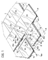
- the flooring according to the invention is preferably composed of a set of modules 10 each constituted, for example, by a sort of large tile (for example 1 metre x 1 metre, these dimensions being indicative and not to be interpreted in a limitative sense) which can be assembled, preferably but not essentially, in staggered courses, the courses being staggered by half a tile as shown in Figure 1. It should however be specified that the solution of the invention lends itself to being realised in the form of an essentially continuous flooring, of indefinite dimensions and/or of being constituted by modules other than tiles, for example as strip, plank or like modular elements.
- the modular structure facilitates the laying of the flooring 1 on a subfloor B such as, for example, a concrete screed or, possibly, a pre-existing floor of a different type (vinyl, linoleum flooring etc) to which the flooring of the invention may even be fixed.
- a subfloor B such as, for example, a concrete screed or, possibly, a pre-existing floor of a different type (vinyl, linoleum flooring etc) to which the flooring of the invention may even be fixed.
- An interesting characteristic of the invention lies in the fact that it provides the possibility of its being laid quickly on a particular site and then being removed with equal rapidity whenever the site is to be used for other purposes.
- the flooring modules 10 are generally configured so as to form a male-female-type coupling.
- each module 10 here shown as a generally square tile, has a projecting male formation 11 along two of its sides, and intended to engage in a corresponding female formation, constituted by a recess 12, formed on the opposing side of an adjacent module 10.
- the coupling of adjacent modules 10 may be made firmer by the interposition of a profiled rod 120, typically a circular-section metal rod, as a fixing element. Both the choice of material and the section of the rod 120, are not, however, fixed for the purposes of carrying out the invention.
- both the male formation 11 and the corresponding recess 12 are provided with respective grooves 11a, 12a extending along their lengths.
- the grooves 11a, 12a of the coupled elements 11, 12 are aligned with each other so as to form a cavity (of circular section in the example illustrated) in which the fixing rod 120 is inserted by longitudinal sliding.
- the presence of the rod 120 thus locks the male formation 11 within the complementary recess 12, fixing the adjacent modules 10 together.
- the male formation 11 may be disengaged from the respective recess 12, allowing the two modules 10 to be separated.
- the coupling of adjacent modules 10 may be consolidated by the provision of pin elements 200 on the lower face of the modules 10 themselves, which, when the flooring is laid, project towards the subfloor B.
- the elements 200 each usually constituted by the proximal portion of the shank of a screw screwed into the module 10, are located at the corners or sides of the modules 10 (for example at the corners or in the middle of the sides as shown schematically in Figure 1).
- the modules 10 in adjacent positions have thus elements 200 located facing each other.
- Coupling elements 202 usually of resilient type, may be engaged with these to hold adjacent modules 10 together.
- the coupling elements 202 in question have the structure shown in Figure 3, that is, a generally arcuate form with a central part 204 having the arcuate structure, or preferably a helical structure, from which branch, in approximately diametrally opposite positions, two arms 206 having respective hooked ends 208.
- the distance between the loops defined by the arms 206 with the respective hooks 208 corresponds approximately - but is rather smaller when the element 202 is in a rest condition - to the distance between two pin elements 200 intended to be connected together.
- the coupling element 202 may thus be snap-engaged so as to connect these pin elements 200, the central part 204 flexing slightly.
- the male-female connection between adjacent modules 10 has proved to be particularly advantageous in the specific field of application, being preferable to coupling solutions with more or less partial superposition used in modular floorings known in the art.
- the coupling solution illustrated in which the male formation 11 fits into the recess 12, has been shown to be very advantageous in that it enables adjacent modules 10 to be fixed very firmly together. This is true as much for the horizontal direction (that is the direction of movement apart of the adjacent modules 10, which is effectively opposed) as for the vertical direction at the edges of the adjacent modules 10. Consequently these modules behave as a single structure particularly with regard to vertical stresses, the continuity of the characteristics being made even more evident by the distribution of the support feet of which more will be said below.
- the flooring 1 of the invention can be seen essentially as a laminated flooring with two components, that is to say:
- the tread layer 13 in turn has a laminar structure, being constituted mainly by a core 14 which carries respective coating layers on one or both of its opposite faces, that is, the upper and lower faces in the normal position of use of the flooring 1, these coatings being applied preferably by the usual techniques of hot glueing under pressure.
- These coatings are indicated 15 and 16 in the embodiment of Figure 2.
- the core portion 14 is made from a material of the type currently termed HDF (High Density Fibre) or MDF (Medium Density Fibre). These are materials in current use, particularly in the furniture industry, constituted essentially by fibres of wood origin aggregated with a binder matrix, typically with a ureic binder.
- HDF High Density Fibre
- MDF Medium Density Fibre
- the tread layer 13 can be considered as an entirely rigid unit, which does not deform, or at least does not deform appreciably, under normal stresses of use.
- normal conditions of use are understood, naturally, those typical for sports flooring or or social use.
- the conditions in question are those corresponding to the stresses applied by athletes using the flooring and by equipment (for example balls) used by them.
- the compliance and resilience characteristics of the flooring 1 as a whole are, however, defined and determined primarily by the compliance characteristics of the support formations represented here by the feet 17.
- the MDF material forming the core 14 of the tread layer 13 may be constituted by a single layer or by several layers 14a of MDF joined by adhesive layers 14b, for example of ureic type.
- the schematic drawing of Figure 2 relates to an embodiment in which there are four layers 14a, each having a thickness of about 5mm, separated by three layers 14b. In any case this solution should not be considered in itself as binding for the purposes of carrying out the invention since, at least for some applications, it would seem to be preferential to form the core 14 as a single layer of material.
- the final three data (internal bond, bending strength and elastic modulus) given above relate to each of the layers 14a and thus relate to a thickness of 5mm.
- the data relating to the core 14 as a whole, having a thickness of about 2cm are correspondingly scaled, particularly when the core 14 has a uniform structure.
- the layer 15, intended to form the upper face of the flooring which is exposed to wear is preferably made from a laminate of the type currently called HPL (High Pressure Laminate), for example with a melamine base, preferably with the following characteristics, determined according to the EN 438 standard:
- HPL High Pressure Laminate
- This choice has the further advantage of associating with the high mechanical strength (including resistance to nicking, scratching, etc) of such laminates, the possibility of giving the layer 15 itself (in accordance with widely known technology which does not need to be explained here) the external appearance of a flooring, for example of wood, with very faithful reproduction of the appearance of such flooring.
- Valid alternatives may, for example, be provided by layers of wood, vinylic material or rubber, of the type currently used for the manufacture of floorings, particularly sports floorings.
- the lower layer 16 is also constituted by a laminate, for example an HPL melamine laminate, the function of which is essentially to provide, together with the core 14, a tread layer 13 having a "balanced" structure, which is highly insensitive to warping (so-called bulging).
- a laminate for example an HPL melamine laminate, the function of which is essentially to provide, together with the core 14, a tread layer 13 having a "balanced" structure, which is highly insensitive to warping (so-called bulging).
- the layer 15 When the layer 15 is present it is preferable for the layer 16 to have mechanical characteristics as close as possible to those of the upper layer 15. This choice has been shown to be preferential due to the fact that it gives the tread layer 13 as a whole completely symmetrical characteristics with regard to contractile stresses and surface extension or the layers 15 and 16.
- the tread layer 13 made in the manner described has the further advantage of being repellent to humidity and even to liquids such as water, exactly because of its very dense structure and the nature of its constituent materials.
- the flooring 1 of the invention is suitable even for use as flooring in the open.
- support formations 17 in the form of feet 14, in the manner which will be described more fully below, is one of various possible choices (all of which fall within the scope of the invention however) including strips, various profiled formations, etc.
- a solution which has been shown to be particularly advantageous is the realisation of support formations in the form of feet comprising a body, preferably in the form of a frusto-conical, hollow body, preferably with an upwardly divergent form and, still more preferably, with a peripheral flange 17b around the upper edge which gives the foot 17 a generally T-shape or mushroom-shape such that it has an enlarged head portion 18 intended to support the tread layer 13 by contact with the lower layer 16.
- each foot 17 is preferably made in the form of an at least partially hollow, closed body, and, hence, with its frusto-conical body having an inner cavity 17a which is closed and sealed by the head 18.
- This latter may be provided with holes 19 around its periphery which enable the foot 17 to be fixed to the lower face of the tread layer 13 by fixing elements such as bolts or screws 20.
- fixing elements such as bolts or screws 20.
- connection such as glueing or the use of clamps.
- Feet 17 having the characteristics described above may be made, for example, by the technique currently termed rotational moulding, usually used for the manufacture of hollow plastics articles, for example balls, etc.
- the availability of support formations such as the feet 17 also allows the spatial distribution of the feet 17 beneath the tread layer 13 to be selected, providing for example, for a very closely - spaced arrangement at the edges of the modules 10.
- a spatial distribution which has been found to be particularly advantageous, under each module 10 in a form of a square plate with dimensions of the order of 100 x 100cm or 120 x 120cm, comprises a regular array of feet 17 arranged in a square grid including an equal number of equispaced rows and columns, with the outer rows and columns, that is the closest rows and columns of the module 10, each situated at a distance from the respective lower edge equal to half the distance separating the said rows and said columns.
- laminate layer could be provided on only the upper face of the core 14.
- the thickness of the core 14 of the tread layer may vary within wide limits: the value currently preferred is in the range of about 15mm to about 35mm, preferably about 27mm.
- each foot 17 may also be mounted the opposite way up from the condition illustrated in the drawings, that is with the minor base in contact with the tread layer 13 and the major base resting on the subfloor B.
Abstract
Description
- plate-like elements forming the bodies of the
modules 10, made in the form of tiles, strips, etc... or even as a continuous layer, intended to form the tread layer proper of the flooring, indicated 13, and - support elements preferably made in the form of
resilient feet 17 intended to support thetread layer 13 on the subfloor B.
- -density:
- 600-1000kg/m3, preferably about 800-850kg/m3
- -formaldehyde content:
- less than 9mg per 100g of material
- -moisture content:
- 3-10%, preferably about 4%
- -internal bond:
- 0.65N/mm2
- -bending strength:
- 36N/mm2
- -elastic modulus:
- 2400N/mm2
- -abrasion resistance
- EN 438/6 -greater than 8000 revs
- -impact strength
- EN 438/12 -from a height of more than 50cm diameter less than 7mm
- -stain resistance
- EN 438/15 -higher than class 4
- -light fastness
- EN 438/16 -higher than grade 6 blue scale
- -resistance to cigarette burns
- EN 438/18-higher than class 3-4
- -resistance to vapour
- EN 438/24 -higher than class 4
- -height:
- from about 15 to about 45mm, preferably about 30mm;
- -diameter of the minor base:
- from about 20mm to about 60mm, preferably about 40mm;
- -diameter of the major base:
- from about 45mm to about
85mm, preferably 65mm; of
these dimensions about 10mm
are attributable to the
flange 17b; - -constituent material:
- all materials, such as polyolefins, which can be moulded by the rotational technique, preferably PVC and even more preferably, plasticised PVC.
Claims (39)
- Laminated flooring, characterised in that it comprises:a tread layer (13) comprising a core (14) of a material selected from the group constituted by HDF and MDF materials and having a layer (15, 16) of laminate applied to at least one of its faces, andsupport formations (17) which support the tread layer (13) in use; the tread layer (13) being arranged as a substantially rigid structure in use whereby the resilient characteristics of compliance of the flooring (1) are determined essentially by the compliance characteristics of the support formations (17).
- Flooring according to Claim 1, characterised in that, in the tread layer (13), the at least one laminate layer (15, 16) is applied to the core (14) so as to adhere firmly thereto so as the form an overall structure which is essentially insensitive to warping deformations.
- Flooring according to Claim 1 or Claim 2, characterised in that layers of laminate (15, 16) are present on both faces of the core (14) and have mechanical characteristics substantially identical to each other whereby the tread layer (13) as a whole is a balanced structure which is essentially insensitive to warping deformations.
- Flooring according to any one of the preceding Claims, characterised in that the at least one laminate layer (15, 16) is a melamine laminate.
- Flooring according to any one of the preceding Claims, characterised in that a laminate layer (15) is applied to that face of the core (14) which is uppermost in use, which laminate layer has a surface appearance imitating wood.
- Flooring according to Claim 1 or Claim 2, characterised in that the laminate layer (16) is present on only that face of the core (14) which is lowermost in use.
- Flooring according to any one of the preceding Claims, characterised in that the said core portion (14) in the said tread layer (13) also has a laminated structure (14a, 14b).
- Flooring according to any one of the preceding Claims, characterised in that the said core portion (14) is constituted by material including ureic binders.
- Flooring according to any one of the preceding Claims, characterised in that the said core portion (14) has a thickness of between about 15mm and about 35mm, preferably about 27mm.
- Flooring according to any one of the preceding Claims, characterised in that the said core portion (14) has a density of about 600 to about 1000kg/m3, preferably from about 800 to about 850kg/m3.
- Flooring according to any one of the preceding Claims, characterised in that the tread layer (13) is made in the form of modules (10).
- Flooring according to Claim 11, characterised in that the modules (10) are made in the form of tiles, strips, or planks.
- Flooring according to Claim 11 or Claim 12, characterised in that the modules (10) are connected together by male - female coupling (11, 12).
- Flooring according to any one of the preceding Claims, characterised in that the support formations (17) are in the form of feet.
- Flooring according to Claim 1 or Claim 14, characterised in that the support formations (17) are distributed non-uniformly beneath the tread layer (13).
- Flooring according to Claim 11 and Claim 15, characterised in the support formations (15) are provided in greater density beneath the edge portions of the modules (10) than beneath the remaining regions of the flooring.
- A support formation (17) for laminated flooring including an upper tread layer (13) arranged as a substantially rigid structure in use, whereby the compliance characteristics of the flooring (1) is determined substantially by the compliance characteristics of the support formations (17), in which the support formation (17) is at least partially hollow (17a).
- A support formation according to Claims 17, characterised in that it includes at least one cavity (17a) closed to the exterior.
- A support formation according to Claim 17 or Claim 18, characterised in that it has a frusto-conical shape.
- A support formation according to Claim 17 or Claim 18, characterised in that it has an upwardly-diverging shape in use.
- A support formation according to any one of Claims 17 to 20, characterised in that it has a T-shape or a mushroom-shape with a head portion (18) surrounded by a peripheral flange (17b).
- A support formation according to any one of Claims 17 to 21, characterised in that it is made from a material which can be rotationally moulded.
- A support formation according to any one of Claims 17 to 21, characterised in that it is made from a material selected from the group constituted by: polyolefins, polyvinyl chloride and plasticised polyvinyl chloride.
- A support formation according to any one of Claims 17 to 23, characterised in that it has a height of between about 15mm and about 45mm.
- A support formation according to any one of Claims 17 to 24, characterised in that it has a height of about 30mm.
- A support formation according to any one of Claims 17 to 25 characterised in that it has a minor base with a diameter of between about 20mm and about 60mm.
- A support formation according to any one of Claims 17 to 26, characterised in that it has a minor base with a diameter of about 40mm.
- A support formation according to any one of Claims 17 to 27, characterised in that it has a major base with a diameter of between about 45mm and about 85mm.
- A support formation according to any one of Claims 17 to 28, characterised in that it has a major base with a diameter of about 65mm.
- A support formation according to any one of Claims 17 to 29, characterised in that it has a major base surrounded by a peripheral flange (17b) with a diametral dimension of about 10mm.
- An anchoring system for laminated flooring including a tread layer (13) and support formations (17) which support the tread layer (13) in use, in which the tread layer (13) is made in the form of modules (10) connected together by generally male-female coupling configurations, the system comprising;pin elements (200) which can project downwardly from the tread layer, andcoupling elements (202) which can extend so as to interconnect pairs of pin elements (200) on adjacent modules of the flooring.
- A system according to Claim 31, characterised in that the pin elements (200) are defined by respective parts of fixing members inserted in the tread layer (13) of the respective flooring module (10).
- A system according to Claim 31 or Claim 32, characterised in that the pin elements (200) are located in peripheral positions in the respective flooring module (10).
- A system according to Claim 33, characterised in that each of the pin elements (200) is located in a position selected from a corner position and an intermediate edge position of the respective flooring module (10).
- A system according to any one of Claims 31 to 34, characterised in that the coupling elements (202) have a central part (204) and two arms (206) terminating with respective hook parts (208).
- A system according to Claim 35, characterised in that the central part (204) is generally springy.
- A system according to Claim 36, characterised in that the central part (204) is constituted by a filiform element wound into a helix.
- A system according to any one of Claims 31 to 37, characterised in that the coupling elements (202) have a generally arcuate shape.
- A system according to any one of Claims 31 to 38, characterised in that the male-female configuration comprises:a male formation (11) projecting along at least one edge of a respective module (10) and having a longitudinal groove (11a), anda receiving recess (12) for housing the male element (11) of an adjacent module (10) extending along a respective edge of a respective module (10) and having a further longitudinal groove (12a) which, when two modules (10) are brought into adjacent positions, is aligned with the longitudinal groove (11a) in the respective male element (11) so as to define a cavity coextensive with the edges of the two adjacent modules (10), anda fixing element (12) which can be inserted in the coextensive cavity (11a,12a) to hold the two adjacent modules (10) together in contact with each other.
Priority Applications (7)
| Application Number | Priority Date | Filing Date | Title |
|---|---|---|---|
| EP97106602A EP0874105B1 (en) | 1997-04-22 | 1997-04-22 | A layered flooring, in particular for athletic facilities |
| DE69730117T DE69730117T2 (en) | 1997-04-22 | 1997-04-22 | Multi-layer flooring, especially for athletic equipment |
| AT97106602T ATE272770T1 (en) | 1997-04-22 | 1997-04-22 | MULTI-LAYER FLOORING, ESPECIALLY FOR ATHLETIC FACILITIES |
| ES97106602T ES2225911T3 (en) | 1997-04-22 | 1997-04-22 | FLOORS AVAILABLE IN LAYERS, IN PARTICULAR FOR ATHLETIC FACILITIES. |
| US08/840,605 US5899038A (en) | 1997-04-22 | 1997-04-22 | Laminated flooring, for example for sports facilities, a support formation and anchoring systems therefor |
| DK97106602T DK0874105T3 (en) | 1997-04-22 | 1997-04-22 | Laminated flooring, especially for athletics facilities |
| CA002203495A CA2203495C (en) | 1997-04-22 | 1997-04-23 | Laminated flooring, for example for sports facilities, a support formation and anchoring systems therefor |
Applications Claiming Priority (3)
| Application Number | Priority Date | Filing Date | Title |
|---|---|---|---|
| EP97106602A EP0874105B1 (en) | 1997-04-22 | 1997-04-22 | A layered flooring, in particular for athletic facilities |
| US08/840,605 US5899038A (en) | 1997-04-22 | 1997-04-22 | Laminated flooring, for example for sports facilities, a support formation and anchoring systems therefor |
| CA002203495A CA2203495C (en) | 1997-04-22 | 1997-04-23 | Laminated flooring, for example for sports facilities, a support formation and anchoring systems therefor |
Publications (2)
| Publication Number | Publication Date |
|---|---|
| EP0874105A1 true EP0874105A1 (en) | 1998-10-28 |
| EP0874105B1 EP0874105B1 (en) | 2004-08-04 |
Family
ID=27170347
Family Applications (1)
| Application Number | Title | Priority Date | Filing Date |
|---|---|---|---|
| EP97106602A Expired - Lifetime EP0874105B1 (en) | 1997-04-22 | 1997-04-22 | A layered flooring, in particular for athletic facilities |
Country Status (7)
| Country | Link |
|---|---|
| US (1) | US5899038A (en) |
| EP (1) | EP0874105B1 (en) |
| AT (1) | ATE272770T1 (en) |
| CA (1) | CA2203495C (en) |
| DE (1) | DE69730117T2 (en) |
| DK (1) | DK0874105T3 (en) |
| ES (1) | ES2225911T3 (en) |
Cited By (4)
| Publication number | Priority date | Publication date | Assignee | Title |
|---|---|---|---|---|
| FR2793508A1 (en) * | 1999-05-12 | 2000-11-17 | Loic Durand | Floor for dance or sporting events has panels with cellular or foam cores sandwiched between fibre, plywood or aluminium skins |
| FR2812894A1 (en) * | 2000-08-11 | 2002-02-15 | Playbois | Shock-absorbing floor, used for sports, is made from panels with at least three dampers and flexion limiters |
| ES2176103A1 (en) * | 2000-10-30 | 2002-11-16 | Liga Nac De Furbol Sala | Demountable e.g. sports event modular track consists of a temporary set of wood faced panels bonded to a felted support and with expanded polystyrene packing |
| US7682684B2 (en) | 2004-11-18 | 2010-03-23 | Mondo S.p.A | Covering material, for instance for floorings |
Families Citing this family (89)
| Publication number | Priority date | Publication date | Assignee | Title |
|---|---|---|---|---|
| SE0001325L (en) * | 2000-04-10 | 2001-06-25 | Valinge Aluminium Ab | Locking systems for joining floorboards and floorboards provided with such locking systems and floors formed from such floorboards |
| US7086205B2 (en) | 1993-05-10 | 2006-08-08 | Valinge Aluminium Ab | System for joining building panels |
| SE512313C2 (en) * | 1998-06-03 | 2000-02-28 | Valinge Aluminium Ab | Locking system and floorboard |
| US7386963B2 (en) * | 1998-06-03 | 2008-06-17 | Valinge Innovation Ab | Locking system and flooring board |
| SE517478C2 (en) * | 1999-04-30 | 2002-06-11 | Valinge Aluminium Ab | Locking system for mechanical hoisting of floorboards, floorboard provided with the locking system and method for producing mechanically foldable floorboards |
| SE517183C2 (en) | 2000-01-24 | 2002-04-23 | Valinge Aluminium Ab | Locking system for mechanical joining of floorboards, floorboard provided with the locking system and method for making such floorboards |
| US6851241B2 (en) * | 2001-01-12 | 2005-02-08 | Valinge Aluminium Ab | Floorboards and methods for production and installation thereof |
| US8028486B2 (en) * | 2001-07-27 | 2011-10-04 | Valinge Innovation Ab | Floor panel with sealing means |
| DE20122778U1 (en) * | 2001-08-10 | 2007-10-25 | Akzenta Paneele + Profile Gmbh | Panel and fastening system for panels |
| US6684592B2 (en) * | 2001-08-13 | 2004-02-03 | Ron Martin | Interlocking floor panels |
| SE525558C2 (en) * | 2001-09-20 | 2005-03-08 | Vaelinge Innovation Ab | System for forming a floor covering, set of floorboards and method for manufacturing two different types of floorboards |
| US8250825B2 (en) * | 2001-09-20 | 2012-08-28 | Välinge Innovation AB | Flooring and method for laying and manufacturing the same |
| SE525661C2 (en) | 2002-03-20 | 2005-03-29 | Vaelinge Innovation Ab | Floor boards decorative joint portion making system, has surface layer with underlying layer such that adjoining edge with surface has underlying layer parallel to horizontal plane |
| EP2281978B1 (en) | 2002-04-03 | 2016-10-12 | Välinge Innovation AB | Method of attaching a strip to a floorboard |
| SE525657C2 (en) | 2002-04-08 | 2005-03-29 | Vaelinge Innovation Ab | Flooring boards for floating floors made of at least two different layers of material and semi-finished products for the manufacture of floorboards |
| US7051486B2 (en) * | 2002-04-15 | 2006-05-30 | Valinge Aluminium Ab | Mechanical locking system for floating floor |
| US8850769B2 (en) * | 2002-04-15 | 2014-10-07 | Valinge Innovation Ab | Floorboards for floating floors |
| US7739849B2 (en) | 2002-04-22 | 2010-06-22 | Valinge Innovation Ab | Floorboards, flooring systems and methods for manufacturing and installation thereof |
| AT413228B (en) * | 2002-08-19 | 2005-12-15 | Kaindl M | COVER PLATE |
| US7677001B2 (en) | 2003-03-06 | 2010-03-16 | Valinge Innovation Ab | Flooring systems and methods for installation |
| US7845140B2 (en) | 2003-03-06 | 2010-12-07 | Valinge Innovation Ab | Flooring and method for installation and manufacturing thereof |
| AT501440A1 (en) * | 2003-03-07 | 2006-09-15 | Kaindl Flooring Gmbh | COVER PLATE |
| US7886497B2 (en) | 2003-12-02 | 2011-02-15 | Valinge Innovation Ab | Floorboard, system and method for forming a flooring, and a flooring formed thereof |
| US20050166516A1 (en) | 2004-01-13 | 2005-08-04 | Valinge Aluminium Ab | Floor covering and locking systems |
| US7748177B2 (en) | 2004-02-25 | 2010-07-06 | Connor Sport Court International, Inc. | Modular tile with controlled deflection |
| SE527570C2 (en) | 2004-10-05 | 2006-04-11 | Vaelinge Innovation Ab | Device and method for surface treatment of sheet-shaped material and floor board |
| US8397466B2 (en) * | 2004-10-06 | 2013-03-19 | Connor Sport Court International, Llc | Tile with multiple-level surface |
| US8407951B2 (en) * | 2004-10-06 | 2013-04-02 | Connor Sport Court International, Llc | Modular synthetic floor tile configured for enhanced performance |
| US7841144B2 (en) * | 2005-03-30 | 2010-11-30 | Valinge Innovation Ab | Mechanical locking system for panels and method of installing same |
| US7454875B2 (en) | 2004-10-22 | 2008-11-25 | Valinge Aluminium Ab | Mechanical locking system for floor panels |
| DK1936068T3 (en) * | 2004-10-22 | 2012-03-19 | Vaelinge Innovation Ab | Method of providing floor panels with a mechanical locking system |
| ITTO20040812A1 (en) | 2004-11-18 | 2005-02-18 | Mondo Spa | MULTIPURPOSE SPORTS INSTALLATION |
| US8215078B2 (en) | 2005-02-15 | 2012-07-10 | Välinge Innovation Belgium BVBA | Building panel with compressed edges and method of making same |
| US20130139478A1 (en) | 2005-03-31 | 2013-06-06 | Flooring Industries Limited, Sarl | Methods for packaging floor panels, as well as packed set of floor panels |
| BE1016938A6 (en) | 2005-03-31 | 2007-10-02 | Flooring Ind Ltd | Floor panel manufacturing method, involves providing panels at lower side with guiding groove and providing two opposite sides with profiled edge regions that comprise coupling parts |
| US8061104B2 (en) | 2005-05-20 | 2011-11-22 | Valinge Innovation Ab | Mechanical locking system for floor panels |
| US20070037461A1 (en) * | 2005-08-09 | 2007-02-15 | Mondo S.P.A. | Laminar covering material |
| US20070068110A1 (en) * | 2005-09-28 | 2007-03-29 | Bing-Hong Liu | Floor panel with coupling means and methods of making the same |
| SE530653C2 (en) | 2006-01-12 | 2008-07-29 | Vaelinge Innovation Ab | Moisture-proof floor board and floor with an elastic surface layer including a decorative groove |
| DE102006006124A1 (en) * | 2006-02-10 | 2007-08-23 | Flooring Technologies Ltd. | Device for locking two building panels |
| BE1017157A3 (en) | 2006-06-02 | 2008-03-04 | Flooring Ind Ltd | FLOOR COVERING, FLOOR ELEMENT AND METHOD FOR MANUFACTURING FLOOR ELEMENTS. |
| SE533410C2 (en) | 2006-07-11 | 2010-09-14 | Vaelinge Innovation Ab | Floor panels with mechanical locking systems with a flexible and slidable tongue as well as heavy therefore |
| US7861482B2 (en) * | 2006-07-14 | 2011-01-04 | Valinge Innovation Ab | Locking system comprising a combination lock for panels |
| US11725394B2 (en) | 2006-11-15 | 2023-08-15 | Välinge Innovation AB | Mechanical locking of floor panels with vertical folding |
| US8689512B2 (en) | 2006-11-15 | 2014-04-08 | Valinge Innovation Ab | Mechanical locking of floor panels with vertical folding |
| SE531111C2 (en) | 2006-12-08 | 2008-12-23 | Vaelinge Innovation Ab | Mechanical locking of floor panels |
| US20080295437A1 (en) * | 2007-05-30 | 2008-12-04 | Dagger Robert K | Attachment system for a modular flooring assembly |
| US8353140B2 (en) | 2007-11-07 | 2013-01-15 | Valinge Innovation Ab | Mechanical locking of floor panels with vertical snap folding |
| EP2235286B1 (en) | 2007-11-07 | 2019-01-02 | Välinge Innovation AB | Mechanical locking of floor panels with vertical snap folding and an installation method to connect such panels |
| RU2485265C2 (en) | 2008-01-31 | 2013-06-20 | Велинге Инновейшн Белджиум Бвба | Mechanical fixator of floor panels, methods for installation and disassembly of panels, method and equipment for creation of locking device, method to connect shifted dowel with panel and dowel blank |
| US8505257B2 (en) * | 2008-01-31 | 2013-08-13 | Valinge Innovation Ab | Mechanical locking of floor panels |
| US8112967B2 (en) * | 2008-05-15 | 2012-02-14 | Valinge Innovation Ab | Mechanical locking of floor panels |
| AU2009338857B2 (en) | 2009-01-30 | 2016-03-10 | Valinge Innovation Ab | Mechanical lockings of floor panels and a tongue blank |
| SI2339092T1 (en) * | 2009-12-22 | 2019-08-30 | Flooring Industries Limited, Sarl | Method for producing covering panels |
| EP2524093B1 (en) | 2010-01-12 | 2020-02-05 | Välinge Innovation AB | Mechanical locking system for floor panels |
| CN102231998B (en) * | 2010-01-22 | 2015-09-09 | 康纳尔运动场国际有限责任公司 | Modular sub-flooring system |
| US8505256B2 (en) * | 2010-01-29 | 2013-08-13 | Connor Sport Court International, Llc | Synthetic floor tile having partially-compliant support structure |
| BR112012018285B1 (en) | 2010-02-04 | 2020-02-18 | Välinge Innovation AB | SET OF FLOOR PANELS |
| US8234830B2 (en) * | 2010-02-04 | 2012-08-07 | Välinge Innovations AB | Mechanical locking system for floor panels |
| RU2525556C2 (en) | 2010-04-15 | 2014-08-20 | Спанолюкс Н.В.-Див. Бальтерио | Block of floor panels |
| US8925275B2 (en) | 2010-05-10 | 2015-01-06 | Flooring Industries Limited, Sarl | Floor panel |
| BE1019501A5 (en) | 2010-05-10 | 2012-08-07 | Flooring Ind Ltd Sarl | FLOOR PANEL AND METHOD FOR MANUFACTURING FLOOR PANELS. |
| BE1019331A5 (en) | 2010-05-10 | 2012-06-05 | Flooring Ind Ltd Sarl | FLOOR PANEL AND METHODS FOR MANUFACTURING FLOOR PANELS. |
| UA109938C2 (en) | 2011-05-06 | 2015-10-26 | MECHANICAL LOCKING SYSTEM FOR CONSTRUCTION PANELS | |
| UA114715C2 (en) | 2011-07-05 | 2017-07-25 | Сералок Інновейшн Аб | Mechanical locking of floor panels with a glued tongue |
| US9725912B2 (en) | 2011-07-11 | 2017-08-08 | Ceraloc Innovation Ab | Mechanical locking system for floor panels |
| US8650826B2 (en) | 2011-07-19 | 2014-02-18 | Valinge Flooring Technology Ab | Mechanical locking system for floor panels |
| DE102012102339A1 (en) * | 2011-07-29 | 2013-01-31 | Hamberger Industriewerke Gmbh | Connection for elastic or plate-shaped components, profile slides and floor coverings |
| US8769905B2 (en) | 2011-08-15 | 2014-07-08 | Valinge Flooring Technology Ab | Mechanical locking system for floor panels |
| US8763340B2 (en) | 2011-08-15 | 2014-07-01 | Valinge Flooring Technology Ab | Mechanical locking system for floor panels |
| US8857126B2 (en) | 2011-08-15 | 2014-10-14 | Valinge Flooring Technology Ab | Mechanical locking system for floor panels |
| US8650824B2 (en) | 2011-12-06 | 2014-02-18 | Johnsonite Inc. | Interlocking floor tile |
| US8726602B2 (en) | 2011-12-06 | 2014-05-20 | Johnsonite Inc. | Interlocking floor tile |
| US8935899B2 (en) | 2012-02-02 | 2015-01-20 | Valinge Innovation Ab | Lamella core and a method for producing it |
| US9216541B2 (en) | 2012-04-04 | 2015-12-22 | Valinge Innovation Ab | Method for producing a mechanical locking system for building panels |
| US8596013B2 (en) | 2012-04-04 | 2013-12-03 | Valinge Innovation Ab | Building panel with a mechanical locking system |
| US8875464B2 (en) | 2012-04-26 | 2014-11-04 | Valinge Innovation Ab | Building panels of solid wood |
| US9140010B2 (en) | 2012-07-02 | 2015-09-22 | Valinge Flooring Technology Ab | Panel forming |
| EP3613920B1 (en) | 2012-11-22 | 2024-01-31 | Ceraloc Innovation AB | Mechanical locking system for floor panels |
| LT3014034T (en) | 2013-06-27 | 2019-11-11 | Vaelinge Innovation Ab | Building panel with a mechanical locking system |
| EA033676B1 (en) | 2013-08-27 | 2019-11-15 | Vaelinge Innovation Ab | Method of producing a semi-product for a building panel |
| US9260870B2 (en) | 2014-03-24 | 2016-02-16 | Ivc N.V. | Set of mutually lockable panels |
| KR102398462B1 (en) | 2014-03-24 | 2022-05-13 | 플로어링 인더스트리즈 리미티드 에스에이알엘 | A set of mutually lockable panels |
| US10246883B2 (en) | 2014-05-14 | 2019-04-02 | Valinge Innovation Ab | Building panel with a mechanical locking system |
| US9458634B2 (en) | 2014-05-14 | 2016-10-04 | Valinge Innovation Ab | Building panel with a mechanical locking system |
| US10138636B2 (en) | 2014-11-27 | 2018-11-27 | Valinge Innovation Ab | Mechanical locking system for floor panels |
| US11203677B2 (en) | 2017-11-03 | 2021-12-21 | American Biltrite (Canada) Ltd. | Resilient surface coverings and methods of making and using thereof |
| US11060302B2 (en) | 2019-01-10 | 2021-07-13 | Valinge Innovation Ab | Unlocking system for panels |
| GB2599732B (en) * | 2020-10-12 | 2023-05-17 | Cap Trac Ltd | Flooring element |
Citations (8)
| Publication number | Priority date | Publication date | Assignee | Title |
|---|---|---|---|---|
| FR1537768A (en) * | 1967-06-30 | 1968-08-30 | Fixed or removable elastic floor | |
| FR1597611A (en) * | 1968-11-14 | 1970-06-29 | ||
| DE2206858A1 (en) * | 1972-02-14 | 1973-08-23 | Karl Kuhn | FLOOR FLOOR, IN PARTICULAR FOR SPORTS HALLS OR THE SAME |
| AU503890B2 (en) * | 1976-06-16 | 1979-09-27 | George Hudson Parquetry Flooring Sales Pty. Ltd. | Floor construction |
| US4274626A (en) * | 1979-04-30 | 1981-06-23 | Amf Incorporated | Exercise floor |
| US5277010A (en) * | 1991-05-31 | 1994-01-11 | Airthrust International, Inc. | Flooring support |
| DE29508540U1 (en) * | 1995-05-23 | 1996-08-29 | Scheying Heinz Friedrich | Cantilever sports floor |
| WO1996027721A1 (en) * | 1995-03-07 | 1996-09-12 | Perstorp Flooring Ab | Flooring panel or wall panel and use thereof |
Family Cites Families (22)
| Publication number | Priority date | Publication date | Assignee | Title |
|---|---|---|---|---|
| US2732706A (en) * | 1956-01-31 | Friedman | ||
| US1425324A (en) * | 1918-11-15 | 1922-08-08 | Hollar Company | Safe or vault wall |
| GB178591A (en) * | 1921-01-29 | 1922-04-27 | Richard Llewelyn Benson Rathbo | Improvements in and relating to the assembling of the units of built-up designs, models and the like |
| FR889320A (en) * | 1942-03-02 | 1944-01-06 | Preussische Bergwerks Und Hu T | Process for establishing reinforced concrete structures |
| DE2534333A1 (en) * | 1975-08-01 | 1977-02-17 | Kraiburg Elastik | Surface and punctiform elastic sports floor panel - comprising rubber elastic covering layer with spaced protuberances underneath |
| US4390580A (en) * | 1981-08-26 | 1983-06-28 | Donovan William J | High pressure laminate for access floor panels |
| US4796392A (en) * | 1986-03-19 | 1989-01-10 | Graham Jr Andrew S | System for interconnecting panels of containers |
| US4694627A (en) * | 1985-05-28 | 1987-09-22 | Omholt Ray | Resiliently-cushioned adhesively-applied floor system and method of making the same |
| US4879857A (en) * | 1985-06-13 | 1989-11-14 | Sport Floor Design, Inc. | Resilient leveler and shock absorber for sport floor |
| US4860516A (en) * | 1988-01-15 | 1989-08-29 | Koller Gregory V | Portable cushioned floor system |
| US5433052A (en) * | 1989-02-08 | 1995-07-18 | Robbins, Inc. | Kerfed hardwood floor system |
| US5303526A (en) * | 1989-02-08 | 1994-04-19 | Robbins, Inc. | Resilient portable floor system |
| JPH0449368A (en) * | 1990-06-15 | 1992-02-18 | Daiken Trade & Ind Co Ltd | Double floor construction |
| FR2667639B1 (en) * | 1991-11-06 | 1993-08-27 | Geraud Pierre | REMOVABLE PARQUET ELEMENT. |
| JPH0657858A (en) * | 1992-08-05 | 1994-03-01 | Mitsubishi Materials Corp | Vertically construction of extruded cement plate |
| US5299401A (en) * | 1993-02-03 | 1994-04-05 | Floyd Shelton | Athletic flooring system |
| US5540025A (en) * | 1993-05-29 | 1996-07-30 | Daiken Trade & Industry Co., Ltd. | Flooring material for building |
| DE9413838U1 (en) * | 1994-08-26 | 1996-01-11 | Hamberger Industriewerke Gmbh | Device for releasable connection of abutting floor panels of a removable sports or multi-purpose hall floor |
| US5618602A (en) * | 1995-03-22 | 1997-04-08 | Wilsonart Int Inc | Articles with tongue and groove joint and method of making such a joint |
| US5713175A (en) * | 1995-06-30 | 1998-02-03 | Mitchell; Steven Glenn | Protective flooring |
| US5682724A (en) * | 1995-09-21 | 1997-11-04 | Connor/Aga Sports Flooring Corporation | Resilient subfloor pad and flooring system employing such a pad |
| US5595427A (en) * | 1996-02-13 | 1997-01-21 | Transfer Flow International, Inc. | Modular countertop |
-
1997
- 1997-04-22 ES ES97106602T patent/ES2225911T3/en not_active Expired - Lifetime
- 1997-04-22 EP EP97106602A patent/EP0874105B1/en not_active Expired - Lifetime
- 1997-04-22 US US08/840,605 patent/US5899038A/en not_active Expired - Lifetime
- 1997-04-22 DE DE69730117T patent/DE69730117T2/en not_active Expired - Fee Related
- 1997-04-22 AT AT97106602T patent/ATE272770T1/en not_active IP Right Cessation
- 1997-04-22 DK DK97106602T patent/DK0874105T3/en active
- 1997-04-23 CA CA002203495A patent/CA2203495C/en not_active Expired - Fee Related
Patent Citations (8)
| Publication number | Priority date | Publication date | Assignee | Title |
|---|---|---|---|---|
| FR1537768A (en) * | 1967-06-30 | 1968-08-30 | Fixed or removable elastic floor | |
| FR1597611A (en) * | 1968-11-14 | 1970-06-29 | ||
| DE2206858A1 (en) * | 1972-02-14 | 1973-08-23 | Karl Kuhn | FLOOR FLOOR, IN PARTICULAR FOR SPORTS HALLS OR THE SAME |
| AU503890B2 (en) * | 1976-06-16 | 1979-09-27 | George Hudson Parquetry Flooring Sales Pty. Ltd. | Floor construction |
| US4274626A (en) * | 1979-04-30 | 1981-06-23 | Amf Incorporated | Exercise floor |
| US5277010A (en) * | 1991-05-31 | 1994-01-11 | Airthrust International, Inc. | Flooring support |
| WO1996027721A1 (en) * | 1995-03-07 | 1996-09-12 | Perstorp Flooring Ab | Flooring panel or wall panel and use thereof |
| DE29508540U1 (en) * | 1995-05-23 | 1996-08-29 | Scheying Heinz Friedrich | Cantilever sports floor |
Cited By (4)
| Publication number | Priority date | Publication date | Assignee | Title |
|---|---|---|---|---|
| FR2793508A1 (en) * | 1999-05-12 | 2000-11-17 | Loic Durand | Floor for dance or sporting events has panels with cellular or foam cores sandwiched between fibre, plywood or aluminium skins |
| FR2812894A1 (en) * | 2000-08-11 | 2002-02-15 | Playbois | Shock-absorbing floor, used for sports, is made from panels with at least three dampers and flexion limiters |
| ES2176103A1 (en) * | 2000-10-30 | 2002-11-16 | Liga Nac De Furbol Sala | Demountable e.g. sports event modular track consists of a temporary set of wood faced panels bonded to a felted support and with expanded polystyrene packing |
| US7682684B2 (en) | 2004-11-18 | 2010-03-23 | Mondo S.p.A | Covering material, for instance for floorings |
Also Published As
| Publication number | Publication date |
|---|---|
| ATE272770T1 (en) | 2004-08-15 |
| DE69730117T2 (en) | 2005-09-01 |
| EP0874105B1 (en) | 2004-08-04 |
| CA2203495C (en) | 2005-08-02 |
| US5899038A (en) | 1999-05-04 |
| DK0874105T3 (en) | 2004-12-13 |
| CA2203495A1 (en) | 1998-10-23 |
| DE69730117D1 (en) | 2004-09-09 |
| ES2225911T3 (en) | 2005-03-16 |
Similar Documents
| Publication | Publication Date | Title |
|---|---|---|
| EP0874105B1 (en) | A layered flooring, in particular for athletic facilities | |
| US6769217B2 (en) | Interconnecting disengageable flooring system | |
| US10066401B2 (en) | Panel for forming a floor covering and method for manufacturing such panels | |
| EP1951971B1 (en) | Decking plank | |
| US5205091A (en) | Modular-accessible-units and method of making same | |
| EP2960397B1 (en) | Multilayer lining plate for horizontal support surfaces and method of manufacturing same | |
| AU761966B2 (en) | Multipanel floor system panel connector with seal | |
| US5111627A (en) | Modular-accessible-units | |
| US11020940B2 (en) | Plate for covering horizontal and vertical surfaces | |
| EP2839094A1 (en) | Prefabricated element for floors or floor baseboards | |
| US11761199B2 (en) | Composite fireproof board and method of processing and preparing the same | |
| AU763968B2 (en) | Multidirectional panels | |
| CN206467960U (en) | Multilayer liner plate for horizontal support face | |
| MXPA01011868A (en) | Decorative laminate panel with water resistant edge. | |
| CA2671446A1 (en) | Floairs | |
| JP3488214B2 (en) | Disconnectable flooring device interconnected | |
| AU760628B2 (en) | Interconnecting disengageable flooring system | |
| ITTO950861A1 (en) | STRATIFIED FLOORING, FOR EXAMPLE FOR SPORTS FACILITIES. | |
| CN112796479A (en) | Solid wood veneer cork composite board structure and mounting method thereof | |
| CA2474132A1 (en) | Interconnecting disengageable flooring system | |
| NZ511336A (en) | Interconnecting disengageable flooring system |
Legal Events
| Date | Code | Title | Description |
|---|---|---|---|
| PUAI | Public reference made under article 153(3) epc to a published international application that has entered the european phase |
Free format text: ORIGINAL CODE: 0009012 |
|
| AK | Designated contracting states |
Kind code of ref document: A1 Designated state(s): AT BE CH DE DK ES FR GB GR IT LI LU NL SE |
|
| AX | Request for extension of the european patent |
Free format text: AL;LT;LV;RO;SI |
|
| 17P | Request for examination filed |
Effective date: 19990412 |
|
| AKX | Designation fees paid |
Free format text: AT BE CH DE DK ES FI FR GB GR IE IT LI LU |
|
| RBV | Designated contracting states (corrected) |
Designated state(s): AT BE CH DE DK ES FR GB GR IT LI LU NL SE |
|
| 17Q | First examination report despatched |
Effective date: 20021105 |
|
| GRAP | Despatch of communication of intention to grant a patent |
Free format text: ORIGINAL CODE: EPIDOSNIGR1 |
|
| RTI1 | Title (correction) |
Free format text: A LAYERED FLOORING, IN PARTICULAR FOR ATHLETIC FACILITIES |
|
| RTI1 | Title (correction) |
Free format text: A LAYERED FLOORING, IN PARTICULAR FOR ATHLETIC FACILITIES |
|
| GRAS | Grant fee paid |
Free format text: ORIGINAL CODE: EPIDOSNIGR3 |
|
| GRAA | (expected) grant |
Free format text: ORIGINAL CODE: 0009210 |
|
| RIN1 | Information on inventor provided before grant (corrected) |
Inventor name: STROPPIANA, FERNANDO |
|
| AK | Designated contracting states |
Kind code of ref document: B1 Designated state(s): AT BE CH DE DK ES FR GB GR IT LI LU NL SE |
|
| REG | Reference to a national code |
Ref country code: GB Ref legal event code: FG4D |
|
| REG | Reference to a national code |
Ref country code: CH Ref legal event code: EP |
|
| REF | Corresponds to: |
Ref document number: 69730117 Country of ref document: DE Date of ref document: 20040909 Kind code of ref document: P |
|
| REG | Reference to a national code |
Ref country code: SE Ref legal event code: TRGR |
|
| REG | Reference to a national code |
Ref country code: CH Ref legal event code: NV Representative=s name: ISLER & PEDRAZZINI AG |
|
| PG25 | Lapsed in a contracting state [announced via postgrant information from national office to epo] |
Ref country code: GR Free format text: LAPSE BECAUSE OF FAILURE TO SUBMIT A TRANSLATION OF THE DESCRIPTION OR TO PAY THE FEE WITHIN THE PRESCRIBED TIME-LIMIT Effective date: 20041104 |
|
| REG | Reference to a national code |
Ref country code: DK Ref legal event code: T3 |
|
| REG | Reference to a national code |
Ref country code: ES Ref legal event code: FG2A Ref document number: 2225911 Country of ref document: ES Kind code of ref document: T3 |
|
| PLBE | No opposition filed within time limit |
Free format text: ORIGINAL CODE: 0009261 |
|
| STAA | Information on the status of an ep patent application or granted ep patent |
Free format text: STATUS: NO OPPOSITION FILED WITHIN TIME LIMIT |
|
| ET | Fr: translation filed | ||
| 26N | No opposition filed |
Effective date: 20050506 |
|
| REG | Reference to a national code |
Ref country code: CH Ref legal event code: PCAR Free format text: ISLER & PEDRAZZINI AG;POSTFACH 1772;8027 ZUERICH (CH) |
|
| PGFP | Annual fee paid to national office [announced via postgrant information from national office to epo] |
Ref country code: ES Payment date: 20090508 Year of fee payment: 13 Ref country code: DK Payment date: 20090415 Year of fee payment: 13 |
|
| PGFP | Annual fee paid to national office [announced via postgrant information from national office to epo] |
Ref country code: SE Payment date: 20090407 Year of fee payment: 13 Ref country code: NL Payment date: 20090405 Year of fee payment: 13 Ref country code: LU Payment date: 20090522 Year of fee payment: 13 Ref country code: FR Payment date: 20090417 Year of fee payment: 13 Ref country code: DE Payment date: 20090429 Year of fee payment: 13 Ref country code: AT Payment date: 20090415 Year of fee payment: 13 |
|
| PGFP | Annual fee paid to national office [announced via postgrant information from national office to epo] |
Ref country code: BE Payment date: 20090428 Year of fee payment: 13 |
|
| PGFP | Annual fee paid to national office [announced via postgrant information from national office to epo] |
Ref country code: CH Payment date: 20090416 Year of fee payment: 13 |
|
| PGFP | Annual fee paid to national office [announced via postgrant information from national office to epo] |
Ref country code: GB Payment date: 20090422 Year of fee payment: 13 |
|
| BERE | Be: lapsed |
Owner name: *MONDO S.P.A. Effective date: 20100430 |
|
| REG | Reference to a national code |
Ref country code: NL Ref legal event code: V1 Effective date: 20101101 |
|
| EUG | Se: european patent has lapsed | ||
| REG | Reference to a national code |
Ref country code: CH Ref legal event code: PL |
|
| REG | Reference to a national code |
Ref country code: DK Ref legal event code: EBP |
|
| GBPC | Gb: european patent ceased through non-payment of renewal fee |
Effective date: 20100422 |
|
| REG | Reference to a national code |
Ref country code: FR Ref legal event code: ST Effective date: 20101230 |
|
| PG25 | Lapsed in a contracting state [announced via postgrant information from national office to epo] |
Ref country code: NL Free format text: LAPSE BECAUSE OF NON-PAYMENT OF DUE FEES Effective date: 20101101 Ref country code: AT Free format text: LAPSE BECAUSE OF NON-PAYMENT OF DUE FEES Effective date: 20100422 |
|
| PG25 | Lapsed in a contracting state [announced via postgrant information from national office to epo] |
Ref country code: LI Free format text: LAPSE BECAUSE OF NON-PAYMENT OF DUE FEES Effective date: 20100430 Ref country code: DE Free format text: LAPSE BECAUSE OF NON-PAYMENT OF DUE FEES Effective date: 20101103 Ref country code: CH Free format text: LAPSE BECAUSE OF NON-PAYMENT OF DUE FEES Effective date: 20100430 |
|
| PG25 | Lapsed in a contracting state [announced via postgrant information from national office to epo] |
Ref country code: GB Free format text: LAPSE BECAUSE OF NON-PAYMENT OF DUE FEES Effective date: 20100422 Ref country code: IT Free format text: LAPSE BECAUSE OF NON-PAYMENT OF DUE FEES Effective date: 20090422 Ref country code: BE Free format text: LAPSE BECAUSE OF NON-PAYMENT OF DUE FEES Effective date: 20100430 |
|
| PG25 | Lapsed in a contracting state [announced via postgrant information from national office to epo] |
Ref country code: DK Free format text: LAPSE BECAUSE OF NON-PAYMENT OF DUE FEES Effective date: 20100503 |
|
| REG | Reference to a national code |
Ref country code: ES Ref legal event code: FD2A Effective date: 20110715 |
|
| PG25 | Lapsed in a contracting state [announced via postgrant information from national office to epo] |
Ref country code: ES Free format text: LAPSE BECAUSE OF NON-PAYMENT OF DUE FEES Effective date: 20110705 |
|
| PGRI | Patent reinstated in contracting state [announced from national office to epo] |
Ref country code: IT Effective date: 20110616 |
|
| PG25 | Lapsed in a contracting state [announced via postgrant information from national office to epo] |
Ref country code: ES Free format text: LAPSE BECAUSE OF NON-PAYMENT OF DUE FEES Effective date: 20100423 |
|
| PG25 | Lapsed in a contracting state [announced via postgrant information from national office to epo] |
Ref country code: FR Free format text: LAPSE BECAUSE OF NON-PAYMENT OF DUE FEES Effective date: 20100430 |
|
| PG25 | Lapsed in a contracting state [announced via postgrant information from national office to epo] |
Ref country code: LU Free format text: LAPSE BECAUSE OF NON-PAYMENT OF DUE FEES Effective date: 20100422 Ref country code: SE Free format text: LAPSE BECAUSE OF NON-PAYMENT OF DUE FEES Effective date: 20100423 |
|
| PGFP | Annual fee paid to national office [announced via postgrant information from national office to epo] |
Ref country code: IT Payment date: 20120403 Year of fee payment: 16 |
|
| PG25 | Lapsed in a contracting state [announced via postgrant information from national office to epo] |
Ref country code: IT Free format text: LAPSE BECAUSE OF NON-PAYMENT OF DUE FEES Effective date: 20130422 |