EP0875200A1 - Blood pressure monitoring apparatus - Google Patents
Blood pressure monitoring apparatus Download PDFInfo
- Publication number
- EP0875200A1 EP0875200A1 EP97107225A EP97107225A EP0875200A1 EP 0875200 A1 EP0875200 A1 EP 0875200A1 EP 97107225 A EP97107225 A EP 97107225A EP 97107225 A EP97107225 A EP 97107225A EP 0875200 A1 EP0875200 A1 EP 0875200A1
- Authority
- EP
- European Patent Office
- Prior art keywords
- pulse wave
- change
- blood pressure
- wave propagation
- propagation time
- Prior art date
- Legal status (The legal status is an assumption and is not a legal conclusion. Google has not performed a legal analysis and makes no representation as to the accuracy of the status listed.)
- Withdrawn
Links
Images


Classifications
-
- A—HUMAN NECESSITIES
- A61—MEDICAL OR VETERINARY SCIENCE; HYGIENE
- A61B—DIAGNOSIS; SURGERY; IDENTIFICATION
- A61B5/00—Measuring for diagnostic purposes; Identification of persons
- A61B5/02—Detecting, measuring or recording pulse, heart rate, blood pressure or blood flow; Combined pulse/heart-rate/blood pressure determination; Evaluating a cardiovascular condition not otherwise provided for, e.g. using combinations of techniques provided for in this group with electrocardiography or electroauscultation; Heart catheters for measuring blood pressure
- A61B5/021—Measuring pressure in heart or blood vessels
- A61B5/02108—Measuring pressure in heart or blood vessels from analysis of pulse wave characteristics
- A61B5/02125—Measuring pressure in heart or blood vessels from analysis of pulse wave characteristics of pulse wave propagation time
-
- A—HUMAN NECESSITIES
- A61—MEDICAL OR VETERINARY SCIENCE; HYGIENE
- A61B—DIAGNOSIS; SURGERY; IDENTIFICATION
- A61B5/00—Measuring for diagnostic purposes; Identification of persons
- A61B5/02—Detecting, measuring or recording pulse, heart rate, blood pressure or blood flow; Combined pulse/heart-rate/blood pressure determination; Evaluating a cardiovascular condition not otherwise provided for, e.g. using combinations of techniques provided for in this group with electrocardiography or electroauscultation; Heart catheters for measuring blood pressure
- A61B5/021—Measuring pressure in heart or blood vessels
- A61B5/022—Measuring pressure in heart or blood vessels by applying pressure to close blood vessels, e.g. against the skin; Ophthalmodynamometers
- A61B5/0225—Measuring pressure in heart or blood vessels by applying pressure to close blood vessels, e.g. against the skin; Ophthalmodynamometers the pressure being controlled by electric signals, e.g. derived from Korotkoff sounds
-
- A—HUMAN NECESSITIES
- A61—MEDICAL OR VETERINARY SCIENCE; HYGIENE
- A61B—DIAGNOSIS; SURGERY; IDENTIFICATION
- A61B5/00—Measuring for diagnostic purposes; Identification of persons
- A61B5/02—Detecting, measuring or recording pulse, heart rate, blood pressure or blood flow; Combined pulse/heart-rate/blood pressure determination; Evaluating a cardiovascular condition not otherwise provided for, e.g. using combinations of techniques provided for in this group with electrocardiography or electroauscultation; Heart catheters for measuring blood pressure
- A61B5/026—Measuring blood flow
- A61B5/0285—Measuring or recording phase velocity of blood waves
Definitions
- the present invention relates to blood pressure monitoring apparatuses to be applied to such fields as requiring continuous blood pressure monitoring for subjects to be treated in operating rooms, intensive care units, a first-aid rooms, an extracorporeal dialysis rooms, and the like. More particularly, the present invention is directed to a blood pressure monitoring apparatus that monitors blood pressure by means of pulse wave propagation time.
- a blood pressure monitoring apparatus that monitors blood pressure by continuously measuring the blood pressure of a subject are a noninvasive blood pressure measurement type based on an oscillometric method by wrapping a cuff around the brachium of a subject and an invasive blood pressure measurement type that involves insertion of a needle into an artery of a subject. Further, blood pressure measurement based on pulse wave propagation velocity is also available as the noninvasive blood pressure measurement type.
- the object of the present invention is to provide a blood pressure monitoring apparatus that can monitor blood pressure continuously, safely, and highly accurately without giving burdens to a subject.
- a blood pressure monitoring apparatus that includes: blood pressure measuring means for measuring blood pressure using a cuff; blood pressure value storage means for storing a blood pressure value measured by the blood pressure measuring means; threshold storage means for storing a pulse wave propagation time change threshold and a blood pressure change threshold that are inputted from an external source; time interval detection reference point detecting means for detecting a time interval detection reference point on a pulse wave at an aorta of a body; pulse wave detecting means for detecting a pulse wave at a peripheral blood vessel appearing with a time delay with respect to the pulse wave at the aorta; pulse wave propagation time counting means for counting a pulse wave propagation time based on detected outputs from the time interval detection reference point detecting means and the pulse wave detecting means; pulse wave propagation time storage means for storing a pulse wave propagation time counted by the pulse wave propagation time counting means when the blood pressure has been measured by the blood pressure measuring means; first logic operation means for calculating a pulse wave
- the second logic operation means calculates the coefficients specific to the subject by a least-squares method using at least two blood pressure values stored in the blood pressure value storage means and the pulse wave propagation times stored in the pulse wave propagation time storage means corresponding to the each blood pressure values, the coefficients being equivalent to a single regression coefficient and a coefficient term when the relationship between blood pressure and pulse wave propagation time is expressed in the form of a single regression line.
- a blood pressure monitoring apparatus including a blood pressure measuring means for measuring blood pressure using a cuff; a storage means for storing a pulse wave propagation time change threshold and a cardiovascular dynamic change threshold, both thresholds being inputted from an external means; a time interval detection reference point detecting means for detecting a time interval detection reference point on a pulse wave at an aorta of a body; a pulse wave detecting means for detecting a pulse wave at a peripheral blood vessel appearing with a time delay with respect to the pulse wave at the aorta; a pulse wave propagation time counting means for counting a pulse wave propagation time based on detected outputs from the time interval detection reference point detecting means and the pulse wave detecting means; a pulse wave propagation time change calculating means for calculating a pulse wave propagation time change from the two pulse wave propagation times counted by the pulse wave propagation time counting means; a cardiovascular dynamic change calculating means for calculating a cardiovascular dynamic change from the time interval detection reference
- the present invention is provided as using a value equivalent to a heart rate change as a cardiovascular dynamic change threshold, causing the cardiovascular dynamic change calculating means to calculate a heart rate change based on the time interval detection reference point, and by causing the second judging means to judge whether or not the heart rate change exceeds the cardiovascular dynamic change threshold equivalent to the heart rate change.
- the present invention is provided as using a value equivalent a rate of change of an amplitude of a pulse wave of a peripheral blood vessel as a cardiovascular dynamic change threshold, and causing the cardiovascular dynamic change calculating means to calculate the rate of change of the amplitude of the pulse wave of the peripheral blood vessel based on the pulse wave at the peripheral blood vessel, and causing the second judging means to judge whether or not the rate of change of the amplitude of the pulse wave exceeds the cardiovascular dynamic change threshold equivalent to the rate of change of the amplitude of the pulse wave of the peripheral blood vessel.
- the present invention is provided as using a value equivalent to a rate of change of a dc component of a pulse wave of a peripheral blood vessel as a cardiovascular dynamic change threshold, causing the cardiovascular dynamic change calculating means to calculate the rate of change of the dc component of the pulse wave based on the pulse wave at the peripheral blood vessel, and causing the second judging means to judge whether or not the rate of change of the dc component of the pulse wave exceeds the cardiovascular dynamic change threshold equivalent to the rate of change of the dc component of the pulse wave of the peripheral blood vessel.
- the present invention is provided as using a heart rate change, a rate of change of an amplitude of a pulse wave of a peripheral blood vessel, and a rate of change of a dc component of a pulse wave of a peripheral blood vessel as cardiovascular dynamic change thresholds; causing the cardiovascular dynamic change calculating means to calculate not only the heart rate change based on the time interval detection reference point, but also the rate of change of the amplitude of the pulse wave and the rate of change of the dc component of the pulse wave based on the pulse wave at the peripheral blood vessel; causing the second judging means to judge whether or not the heart rate change exceeds the cardiovascular dynamic change threshold equivalent to the heart rate change, whether or not the rate of change of the amplitude of the pulse wave exceeds the cardiovascular dynamic change threshold equivalent to the rate of change of the amplitude of the pulse wave of the peripheral blood vessel, and whether or not the rate of change of the dc component of the pulse wave exceeds the cardiovascular dynamic change threshold equivalent to the rate of change of the dc component of the peripheral blood vessel; and
- the blood pressure monitoring apparatuses of the present invention are provided as not only judging whether or not the pulse wave propagation time change exceeds the preset pulse wave propagation time change threshold, but also judging whether or not the cardiovascular dynamic change, i.e., the heart rate change, the rate of change of the amplitude of the pulse wave at the peripheral blood vessel, or the rate of change of the dc component of the pulse wave at the peripheral blood vessel, exceed the preset cardiovascular dynamic change thresholds thereof and starting a blood pressure measurement for the subject if any one of the changes is judged to exceed the threshold thereof. Therefore, the burden given to the subject in the past can be reduced.
- the cardiovascular dynamic change i.e., the heart rate change, the rate of change of the amplitude of the pulse wave at the peripheral blood vessel, or the rate of change of the dc component of the pulse wave at the peripheral blood vessel
- the blood pressure monitoring apparatuses of the present invention are also characterized as allowing a feeble blood pressure fluctuation that cannot be detected by the pulse wave propagation time change to be detected by the cardiovascular dynamic change. Therefore, a sudden turn for the worse in the blood pressure fluctuation of the subject can be monitored more reliably.
- the principle of a blood pressure measuring method based on pulse wave propagation velocity is as follows.
- the specific point of a pulse wave on the side of a peripheral blood vessel such as a finger or a ear appears with a delay with respect to the specific point of an aortic pulse wave.
- This delay time is the pulse wave propagation time.
- a pulse wave propagation velocity corresponding to a pulse wave propagation time at a predetermined distance appears as a function of the volume elasticity of a blood vessel.
- the volume elasticity of a blood vessel increases with increasing blood pressure, and the blood vessel wall becomes hard, which in turn increases propagation velocity. Therefore, a blood pressure change can be detected from the pulse wave propagation velocity.
- a sphygmomanometer using this pulse wave propagation time must be calibrated by measuring blood pressure through other means, e.g., using a cuff, and referring to the measured results.
- Such calibration requires measurements of both blood pressure values and pulse wave propagation times when a subject is, e.g., at rest and in exercise.
- the blood pressure values P1, P2 are given as follows.
- Blood pressure fluctuations of a subject can be monitored by consecutively measuring the pulse wave propagation time.
- a pulse wave propagation time change threshold ⁇ Ts it is judged that a sudden change has occurred in the blood pressure fluctuation of a subject, and a blood pressure measurement is made using the cuff at this moment. Further, in this case, noise may be picked up in the measured values that are to be used for calculating ⁇ , ⁇ or ⁇ , ⁇ may thereafter fluctuate. Therefore, ⁇ , ⁇ are calculated again when the pulse wave propagation time change ⁇ T exceeds the pulse wave propagation time change threshold ⁇ Ts. Further, the pulse wave propagation time change threshold ⁇ Ts is calculated based on the calculated value ⁇ to update the current pulse wave propagation time change threshold ⁇ Ts.
- the above operation prevents the subject from being burdened as in the case where blood pressure measurements are continuously made using the cuff at a predetermined cycle, which in turn contributes to significantly reducing burdens given to the subject and allowing blood pressure fluctuations to be monitored with high accuracy.
- a blood pressure monitoring apparatus which is a first embodiment of the present invention will now be described with reference to the drawings.
- Fig. 1 is a block diagram showing an exemplary configuration of the blood pressure monitoring apparatus, which is the embodiment of the present invention.
- a cuff 2 is designed to be attached to a brachium or finger of a subject, and the inside thereof is opened or closed with respect to the atmosphere by a exhaust valve 3. Air is supplied to the cuff 2 by a pressuring pump 4.
- a pressure sensor 5 is arranged in the detecting porion (not shown) of the blood pressure monitoring apparatus to which the static air pressure inside a cuff is transmitted through the tube, and the output of the sensor is detected by a cuff pressure detecting section 6.
- the output of the cuff pressure detecting section 6 is converted into a digital signal by an A/D converter 7 and is received by a CPU (central processing unit) 1.
- a time interval detection reference point detecting section 8 is provided to detect a timing at which the aortic blood pressure reaches a bottom value thereof substantially simultaneously with generation of an ECG R wave.
- the output of this detecting section 8 is received by the CPU 1 while converted into a digital signal by an A/D converter 9.
- the time interval detection reference point detecting section 8 can be constructed of electrodes that are attached to the chest of a subject and an ECG R wave detecting section to which the electrodes are connected. It may be noted that the time interval detection reference point detecting section 8 can be constructed also of a photoelectric pulse wave sensor or pressure pulse wave sensor for detecting an aortic pulse wave, and a pulse wave detecting section to which such sensor is connected.
- a photoelectric pulse wave sensor 10 is attached to, e.g., a finger of a subject to measure pulse waves at a peripheral blood vessel.
- the output of the photoelectric pulse wave sensor 10 is sent to a pulse wave detecting section 11, the pulse wave at the part of the subject to which the sensor is attached can be detected.
- the output of the pulse wave detecting section 11 is received by the CPU 1 while converted into a digital signal by an A/D converter 12.
- Input means 13 inputs an initial pulse wave propagation time change threshold ⁇ Ts, a blood pressure change threshold ⁇ BPs, a maximum calibration point count m, and the like.
- a key 14 is pressed when blood pressure measurement is to be made manually using the cuff 2 and when the pulse wave propagation time change threshold ⁇ Ts is to be updated.
- the CPU 1 executes a processing program based on signals sent from the A/D converters 7, 9, 12 and the key 14, outputs necessary control signals to the exhaust valve 3, the pressuring pump 4, and the like, and supplies the processed results to a display 15.
- a ROM 16 that is connected to the CPU 1 has the processing program stored therein.
- a RAM 17 are not only data areas arranged for storing blood pressure measurement data but also a counter, a flag, buffers, and registers arranged. Here, the following counter, flag, buffers, and registers are provided.
- the cuff 2, the exhaust valve 3, the pressuring pump 4, the pressure sensor 5, the cuff pressure detecting section 6, and the A/D converter 7 constitute the blood pressure measuring means.
- the RAM 16 corresponds to the blood pressure value storage means, the threshold storage means, and the pulse wave propagation time storage means.
- the time interval detection reference point detecting section 8 and the A/D converter 9 constitute the time interval detection reference point detecting means.
- the photoelectric pulse wave sensor 10, the pulse wave detecting section 11, and the A/D converter 12 constitute the pulse wave detecting means.
- the CPU 1 corresponds to the pulse wave propagation time counting means, the first logic operation means, the second logic operation means, the third logic operation means, the control means, and the judging means.
- Fig. 2 is a general flowchart showing an operation of the blood pressure monitoring apparatus.
- Step S2 Upon feeding power to the apparatus, an initial pulse wave propagation time change threshold ⁇ Ts, a blood pressure change threshold ⁇ BPs, and a maximum calibration point count m are inputted from the input means 13, and these inputted values are stored in the registers R ⁇ Ts, R ⁇ BPs, Rm in Step S1. Then, in Step S2, the ring buffer address counter i is set to "1", and the maximum calibration point count flag k is reset to "0". Then, in Step S3, it is judged whether or not there is an input through the key 14. If it is judged negatively, then it is judged whether or not the values ⁇ , ⁇ are present in Step S4. Since the values ⁇ , ⁇ are not present at this point of time, Step S3 will be executed again. If there is no input through the key for an initial blood pressure measurement, Steps S3 and S4 will be executed repetitively.
- Step S5 a blood pressure measurement is made using the cuff 2 in Step S5, and the measured value BPt is written to the ring buffer BP(i) that is specified by the ring buffer address counter i being equal to "1".
- Step S6 the pulse wave propagation time Tt 1 is counted based on the data from the A/D converters 9, 12, and the measured value is written to the ring buffer T(i) that is specified by the ring buffer address counter i being equal to "1".
- Step S7 the blood pressure value BPt already measured and written to the ring buffer BP(1) is displayed on the display 15.
- Step S3 the pulse wave propagation time Tt 1 is written to the register RTc in Step S12. After this processing in Step S11. Then in step 12, the ring buffer address counter i is incremented by "1" after this processing in step 12 has been executed, Step S3 will be executed again to judge whether or not there is an input through the key.
- Step S8 if it is judged in Step S8 that the ring buffer address counter i has reached the maximum calibration point count m, the maximum calibration point count flag k is set to "1" in Step S9, and the processing for calculating the values ⁇ , ⁇ is executed in Step S13. This processing is executed based on the blood pressure values and pulse wave propagation times corresponding to the maximum calibration point count. As described above, the values ⁇ , ⁇ are the coefficients specific to an individual subject.
- Step S10 when the maximum calibration point count flag k is set to "0" and the ring buffer address counter i has a count of 2 or more in Step S10, the processing for calculating ⁇ , ⁇ is executed based on at least two blood pressure values BPt and pulse wave propagation times Tt 1 in Step S13.
- the processing for calculating the pulse wave propagation time change threshold ⁇ Ts is executed in Step S14.
- the pulse wave propagation time change threshold ⁇ Ts can be obtained by dividing the blood pressure change threshold ⁇ BPs by the calculated value ⁇ .
- the pulse wave propagation time change threshold ⁇ Ts is written to the register R ⁇ Ts in Step S15. That is, the pulse wave propagation time change threshold ⁇ Ts is updated.
- Step S3 the pulse wave propagation time Tt 1 is written to the register RTc in Step S11, and in step 12, the ring buffer address counter i is incremented by "1", then Step S3 will thereafter be executed to judge whether or not there is an input through the key.
- the blood pressure value BPt is measured, and the pulse wave propagation time Tt 1 is also counted. As a result, the counted pulse wave propagation time Tt 1 is written to the register RTc, and the ring buffer address counter i has a count of "2".
- Step S20 The pulse wave propagation time change ⁇ T is calculated from
- Step S5 will be executed to take care of such a sudden change in the blood pressure fluctuation of the subject; i.e., a blood pressure measurement is made using the cuff 2, and the measured blood pressure value BPt is written to the register RBPt. Further, the pulse wave propagation time Tt 1 is counted in Step S6, and the counted value is written to the register RTt 1 .
- the measured blood pressure value BPt is displayed on the display 15 in Step S7.
- Step S8 it is judged whether or not the ring buffer address counter i has reached the maximum calibration point count m.
- the maximum calibration point count flag k is set to "0" and that the ring buffer address counter i has a count of "2" or more. Therefore, the processing for calculating ⁇ , ⁇ is executed in Step S13.
- Step S14 the processing for calculating the pulse wave propagation time change threshold ⁇ Ts is executed in Step S14.
- Step S15 the processing for updating the pulse wave propagation time change threshold ⁇ Ts is executed.
- the pulse wave propagation time Tt 1 that has been written in the register RTt 1 is written to the register RTc.
- step 12 the ring buffer address counter i is incremented by "1".
- the blood pressure value is calculated from the measured pulse wave propagation time Tt and the values ⁇ , ⁇ in the processing from Steps S16 to S19.
- Such processing from Steps S16 to S19 is executed based on the same ⁇ , ⁇ unless the pulse wave propagation time change ⁇ T exceeds the pulse wave propagation time change threshold ⁇ Ts. If the pulse wave propagation time change ⁇ T exceeds the pulse wave propagation time change threshold ⁇ Ts, a blood pressure measurement is made using the cuff 2, so that new ⁇ , ⁇ are calculated, and the pulse wave propagation time change threshold ⁇ Ts is updated.
- the values ⁇ , ⁇ are calculated based on the blood pressure values and pulse wave propagation times accumulated in the ring buffers up to that point of time.
- the values ⁇ , ⁇ are calculated based on the blood pressure value and pulse wave propagation time corresponding to such maximum calibration point count.
- Fig. 4 is a trend graph showing the measured blood pressure values BPt in function of time and the counted pulse wave propagation times Tt in function of time.
- the pulse wave propagation time change ⁇ T exceeds the pulse wave propagation time change threshold ⁇ Ts after an initial blood pressure measurement has been made using the cuff 2
- the pulse wave propagation time Tt is continuously counted. If ⁇ T > ⁇ Ts at some point of time, then a blood pressure measurement is made using the cuff 2.
- the ring buffer address counter i has a count of "2", and ⁇ , ⁇ are calculated at this point of time.
- the pulse wave propagation time change threshold ⁇ Ts is calculated from the calculated value a and updated. After the updating operation has been performed, the pulse wave propagation time Tt is consecutively counted. The pulse wave propagation time change threshold ⁇ Ts is thereafter updated every time ⁇ T > ⁇ Ts.
- Fig. 3 is a flowchart showing the processing for calculating ⁇ , ⁇ in the blood pressure monitoring apparatus according to this embodiment.
- Step S31 It is judged in Step S31 whether or not the maximum calibration point count flag k is set to "1". If it is judged negatively, i.e., if the number of data pieces of the blood pressure values BPt and pulse wave propagation times Tt 1 written to the ring buffers BP(i) and T(i) has not reached the maximum calibration point count m, then ⁇ , ⁇ are calculated based on the currently available number of data pieces in Step S32. In this case, ⁇ , ⁇ are calculated by the least-squares method.
- ⁇ is obtained by dividing the sum of products of deviatoric of the blood pressure value BPt and deviatoric of the pulse wave propagation time Tt 1 by the sum of deviatoric squares of the pulse wave propagation time Tt 1 , and ⁇ is obtained by subtracting the product of the average of the pulse wave propagation times Tt 1 and ⁇ from the average of the blood pressure values BPt.
- Step S32 ⁇ , ⁇ are calculated from the blood pressure values BPt and pulse wave propagation times Tt 1 corresponding to a value smaller than the maximum calibration point count m, i.e., a count specified by the ring buffer address counter.
- the value ⁇ to be calculated is given as indicated in Eq. 1.
- the BPav is an average of the values in the ring buffers BP(1) to BP(i)
- the Tav is an average of the values in the ring buffers T(1) to T(i).
- ⁇ BP(i) - ⁇ ⁇ T(i)
- Step S31 if it is judged in Step S31 that the maximum calibration point count flag k is set to "1", i.e., the number of data pieces of the blood pressure values BPt and pulse wave propagation times Tt 1 written in the ring buffers BP(i) and T(i) has reached the maximum calibration point count m, ⁇ , ⁇ are calculated based on the data corresponding to the maximum calibration point count m in Step S33. In this case also, ⁇ , ⁇ are calculated by the least-squares method.
- Step S33 ⁇ , ⁇ are calculated from the blood pressure values BPt and pulse wave propagation times Tt 1 corresponding to the maximum calibration point count m that is a count specified by the ring buffer address counter i.
- the value ⁇ is calculated by an equation indicated in Eq. 2.
- the BPav is an average of the values in the ring buffers BP(1) to BP(m)
- the Tav is an average of the values in the ring buffers T(1) to T(m).
- ⁇ BP(m) - ⁇ ⁇ T(m)
- each set of data consisting of a blood pressure value BPt and a pulse wave propagation time Tt 1 , temporarily stored in the ring buffer BP(i), ⁇ , ⁇ are calculated by the least-squares method based on such two sets of data.
- Step S34 it is judged in Step S34 whether or not the ring buffer address counter i indicates a count that is equal to the maximum calibration point count m or more. If it is judged affirmatively, the ring buffer address counter i is set to "1", and the ⁇ , ⁇ calculating subroutine is terminated. From then on, the values ⁇ , ⁇ are calculated by the least-squares method for all the data stored in the ring buffers (for m pieces of data). If, on the other hand, the ring buffer address counter i has a count smaller than the maximum calibration point count m, the subroutine is terminated directly.
- the blood pressure value BPt is measured with the cuff 2, and the measured blood pressure value BPt is displayed.
- the pulse wave propagation time Tt 1 is counted.
- a measurement of the pulse wave propagation time Tt is started.
- the pulse wave propagation time Tt is consecutively counted, and the pulse wave propagation time change ⁇ T is calculated every time the pulse wave propagation time Tt is counted, and the calculated pulse wave propagation time change ⁇ T is compared with the pulse wave propagation time change threshold ⁇ Ts.
- the pulse wave propagation time change ⁇ T exceeds the pulse wave propagation time change threshold ⁇ Ts, not only the blood pressure value BPt is measured again with the cuff 2, but also the pulse wave propagation time Tt 1 is counted again. Further, the values ⁇ , ⁇ specific to a subject are calculated. Then, the pulse wave propagation time change threshold ⁇ Ts is calculated from the calculated coefficient ⁇ , and the current pulse wave propagation time change threshold ⁇ Ts is updated.
- the coefficients ⁇ , ⁇ are calculated based on the least-squares method from at least two sets of data, each set of data consisting of a blood pressure value BPt and a pulse wave propagation time Tt 1 , which are stored in the past including the blood pressure value BPt and pulse wave propagation time Tt 1 currently obtained.
- the pulse wave propagation time change ⁇ T exceeds the pulse wave propagation time change threshold ⁇ Ts while consecutively counting the pulse wave propagation time Tt, not only sudden changes in the blood pressure fluctuation of a subject are monitored, but also a blood pressure measurement is made using the cuff 2 correctly at the time of a sudden change in blood pressure fluctuation, and the pulse wave propagation time change threshold ⁇ Ts is updated. Therefore, not only burdens given to the subject in the conventional example can be reduced significantly, but also blood pressure fluctuations can be monitored with high accuracy.
- pulse wave propagation time counting processing may be made every heart beat or may be made in such a manner that the counting processing is executed at a predetermined time interval or for predetermined heart rates and an average of the counts is then calculated. By calculating the average, accurate pulse wave propagation time counting free from irregularly occurring noise can be implemented.
- a blood pressure monitoring apparatus of the noninvasive measurement type utilizes pulse wave propagation velocity (pulse wave propagation time at a predetermined distance).
- the principle of a blood pressure measuring method based on pulse wave propagation velocity is as follows.
- the specific point of a pulse wave on the peripheral blood vessel side appears with a delay with respect to the specific point of an aortic pulse wave.
- This delay time is the pulse wave propagation time.
- a pulse wave propagation velocity corresponding to a pulse wave propagation time at a predetermined distance appears as a function of the volume elasticity of a blood vessel.
- the volume elasticity of a blood vessel increases with increasing blood pressure, and the blood vessel wall becomes hard, which in turn increases propagation velocity.
- blood pressure fluctuations can be calculated from pulse wave propagation velocity.
- the blood pressure fluctuations of a subject can be monitored.
- a pulse wave propagation time change ⁇ T exceeds a preset pulse wave propagation time change threshold ⁇ Ts
- a heart rate change ⁇ HR exceeds a cardiovascular dynamic change threshold ⁇ HRs equivalent to a preset heart rate change
- a rate of change of the amplitude of a pulse wave of a peripheral blood vessel r 1 exceeds a cardiovascular dynamic change threshold r 1 s equivalent to a preset rate of change of the amplitude of a pulse wave of a peripheral blood vessel
- a rate of change of the dc component of a pulse wave of a peripheral blood vessel r 2 exceeds a cardiovascular dynamic change threshold r 2 s equivalent to a preset rate of change of the dc component of a pulse wave of a peripheral blood vessel
- the heart rate change ⁇ HR, the rate of change of the amplitude of the pulse wave of the peripheral blood vessel r 1 , and the rate of change of the dc component of the pulse wave of the peripheral blood vessel r 2 are cardiovascular dynamic changes, and these changes are more critical than the pulse wave propagation time change ⁇ T. Therefore, these changes can detect even a feeble change in blood pressure which cannot be detected by the pulse wave propagation time. As a result, a sudden turn for the worse in blood pressure fluctuation can be monitored with extremely high accuracy.
- a blood pressure monitoring apparatus which is an embodiment of the invention, will now be described with reference to the drawings.
- Fig. 6 is a block diagram showing an exemplary configuration of the blood pressure monitoring apparatus of the invention.
- a cuff 102 is designed to be attached to a brachium or finger of a subject and the inside thereof is opened or closed with respect to the atmosphere by an exhaust valve 103. Air is supplied to the cuff 102 by a pressuring pump 104.
- a pressure sensor 105 is arranged on the cuff main body, and the output of the sensor is detected by a cuff pressure detecting section 106.
- the output of the cuff pressure detecting section 106 is converted into a digital signal by an A/D converter 107 and is received by a CPU (central processing unit) 101.
- a time interval detection reference point detecting section 108 is provided to detect a timing at which the aortic blood pressure reaches a bottom value thereof substantially simultaneously with generation of an ECG R wave.
- the output of this detecting section 8 is received by the CPU 101 while converted into a digital signal by an A/D converter 109.
- the time interval detection reference point detecting section 108 can be constructed of electrodes that are attached to the chest of a subject and an ECG R wave detecting section to which the electrodes are connected. It may be noted that the time interval detection reference point detecting section 108 can be constructed also of a photoelectric pulse wave sensor or pressure pulse wave sensor for detecting an aortic pulse wave, and a pulse wave detecting section to which such sensor is connected.
- a photoelectric pulse wave sensor 110 is attached to, e.g., a finger of a subject to measure pulse waves at peripheral blood vessels.
- the pulse wave at a position of the subject to which the sensor is attached can be detected.
- the pulse wave detecting section 111 outputs signals by separating the pulse wave into an ac component and a dc component.
- the ac component of the pulse wave is received by the CPU 101 while converted into a digital signal by an A/D converter 112. Further, the dc component of the pulse wave is received by the CPU 101 while converted into a digital signal by an A/D converter 113.
- An input means 114 inputs an initial pulse wave propagation time change threshold ⁇ Ts, and initial cardiovascular dynamic change thresholds ⁇ HRs, r 1 s, and r 2 s.
- ⁇ HRs is a value equivalent to a change in heart rate
- r 1 s is a value equivalent to the rate of change in the amplitude of a pulse wave of a peripheral blood vessel
- r 2 s is a value equivalent to the rate of change in the dc component of a pulse wave of a peripheral blood vessel.
- a key 115 is pressed when blood pressure is measured manually using the cuff 102.
- the CPU 101 executes a processing program based on signals given from the A/D converters 107, 109, 112, 113 and the key 115, outputs necessary control signals to the discharge valve 103, the pressure pump 104, and the like, and supplies the processing result to a display 116.
- a ROM 117 that is connected to the CPU 101 has the processing program stored therein.
- a RAM 118 are various registers and data areas arranged for storing blood pressure measurement data.
- the cuff 102, the exhaust valve 103, the pressuring pump 104, the pressure sensor 105, the cuff pressure detecting section 106, and the A/D converter 107 constitute a blood pressure measuring means.
- the RAM 118 corresponds to a storage means.
- the time interval detection reference point detecting section 108 and the A/D converter 109 constitute a time interval detection reference point detecting means.
- the photoelectric pulse wave sensor 110, the pulse wave detecting section 111, and the A/D converters 112, 113 constitute a pulse wave detecting means.
- the CPU 101 corresponds to a pulse wave propagation time counting means, a pulse wave propagation time change calculating means, a cardiovascular dynamic change calculating means, a first judging means, a second judging means, and a control means.
- Fig. 7 is a flowchart showing an operation of the blood pressure monitoring apparatus.
- Step S1 the pulse wave propagation time change threshold ⁇ Ts, the cardiovascular dynamic change thresholds ⁇ HRs, r 1 s, and r 2 s are inputted from the input means 114 and written to the RAM 118. It may be noted that these thresholds ⁇ Ts, ⁇ HRs, r 1 s, and r 2 s are preset by considering the weight, height, etc. of a subject.
- Step S2 After the respective thresholds have been written to the RAM 118, it is judged in Step S2 whether or not an input is given through the key 115. If it is judged affirmatively, the exhasut valve 103 and the pressuring pump 104 are controlled by the CPU 1 in Step S3, and a blood pressure measurement is made on a subject using the cuff 102. Data received from the A/D converter 107 is processed internally by the CPU 101, and a blood pressure value BP measured by an oscillometric method is written to the RAM 118.
- Step S4 is executed. That is, in Step S4, the pulse wave propagation time T 2 stored in the register RT 2 is moved to the register RT 1 ; the heart rate HR 2 stored in the register RHR 2 is moved to the register RHR 1 ; the amplitude AC 2 of the pulse wave stored in the register RAC 2 is moved to the register RAC 1 ; and the dc component DC 2 of the pulse wave stored in the register RDC 2 is moved to the register RDC 1 .
- the pulse wave propagation time T 2 is not counted, the operation of moving the data to the registers RT 1 , RHR 1 , RAC 1 , and RDC 1 is not actually performed.
- the previously measured blood pressure value BP is displayed on the display 16 in Step S5. Then, Step S2 will be executed.
- Step S2 whether or not an input has been made through the key is judged again. If it is judged negatively, the pulse wave propagation time T 2 equivalent to a time interval from a timing at which an aortic pulse wave reaches the bottom value thereof substantially simultaneously with generation of an ECG R wave to a timing at which the pulse wave at a peripheral blood vessel reaches the bottom value thereof based on data from the A/D converters 109, 112, and the measured value is stored in the register RT 2 of the RAM 118 in Step S6. Further, the heart rate and the amplitude and dc component of the pulse wave at the peripheral blood vessel are measured, and the measured values are stored in the registers RHR 2 , RAC 2 , and RDC 2 of the RAM 118.
- ⁇ HR
- r 1
- r 2
- ⁇ HR
- r 1
- r 2
- Step S9 After the pulse wave propagation time change ⁇ T, the heart rate change ⁇ HR, the pulse wave amplitude change rate r 1 , and the pulse wave dc component change rate r 2 have been calculated, Step S9 will be executed. That is, in Step S9, it is judged whether or not the pulse wave propagation time change ⁇ T calculated in Step S8 exceeds the preset pulse wave propagation time change threshold ⁇ Ts; it is judged whether or not the heart rate change ⁇ HR calculated in Step S8 exceeds the value ⁇ HRS equivalent to the preset heart rate change; it is judged whether or not the pulse wave amplitude change rate r 1 calculated in Step S8 exceeds the value r 1 s equivalent to the preset rate of change of the amplitude of the pulse wave at the peripheral blood vessel; and it is judged whether or not the pulse wave dc component change rate r 2 calculated in Step S8 exceeds the value r 2 s equivalent to the preset rate of change of the dc component of the pulse wave at the peripheral blood
- Step S2 it is judged whether or not ⁇ T > ⁇ Ts, ⁇ HR > ⁇ HRs, r 1 > r 1 s, and r 2 > r 2 s are satisfied. If none of the above inequalities is satisfied, then, a series of operation is repeated starting at Step S2.
- Step S3 in order to take care of the sudden turn for the worse in the blood pressure fluctuation of the subject, a blood pressure measurement is made using the cuff 102, and the measured value BP is written to a data area in the RAM 118.
- Step S4 the pulse wave propagation time T 2 stored in the register RT 2 is moved to the register RT 1 ; the heart rate HR 2 stored in the register RHR 2 is moved to the register RHR 1 ; the amplitude AC 2 of the pulse wave stored in the register RAC 2 is moved to the register RAC 1 ; and the dc component DC 2 of the pulse wave stored in the register RDC 2 is moved to the register RDC 1 .
- Step S5 the blood pressure value BP measured in Step S3 is displayed on the display 116. Step S2 will thereafter be executed.
- this embodiment is characterized as constantly measuring the pulse wave propagation time and not only judging whether or not the pulse wave propagation time change ⁇ T exceeds the pulse wave propagation time change threshold ⁇ Ts but also judging whether or not the cardiovascular dynamic changes ⁇ HR, r 1 , r 2 exceed the thresholds thereof ⁇ HRs, r 1 s, r 2 s, so that a sudden turn for the worse in the blood pressure fluctuation of a subject can be monitored and a blood pressure measurement using the cuff 2 is made reliably if any one of the values exceeds the threshold thereof. Therefore, the burden given to the subject in the past can be reduced.
- this embodiment is also characterized as allowing a feeble blood pressure fluctuation that cannot be detected by the pulse wave propagation time change to be detected by the cardiovascular dynamic change. Therefore, a sudden turn for the worse in the blood pressure fluctuation of the subject can be monitored more reliably.
- pulse wave propagation time counting processing may be made every heart beat or may be made in such a manner that the processing is executed at a predetermined time interval or for predetermined heart rates and an average of the counts can then be calculated. This technique of calculating the average allows accurate pulse wave propagation time counting free from irregularly occurring noise to be made.
- a pulse wave propagation time change is calculated every time a pulse wave propagation time is counted consecutively, and the calculated pulse wave propagation time change is compared with a pulse wave propagation time change threshold; if the pulse wave propagation time change exceeds the pulse wave propagation time change threshold, a blood pressure measurement is made using a cuff and a pulse wave propagation time is counted; in this case, if there are at least two sets of data, each set of data consisting of a blood pressure value and a pulse wave propagation time obtained in a blood pressure measurement, including those data stored in the past, coefficients specific to a subject are calculated based on the least-squares method from the respective two sets of data; further, the pulse wave propagation time change threshold is calculated from a calculated coefficient specific to the subject; and the current pulse wave propagation time change threshold is updated.
- the blood pressure monitoring apparatuses of the present invention are not only judging whether or not the pulse wave propagation time change exceeds the preset pulse wave propagation time change threshold, but also judging whether or not the cardiovascular dynamic change, i.e., the heart rate change, the rate of change of the amplitude of the pulse wave at the peripheral blood vessel, or the rate of change of the dc component of the pulse wave at the peripheral blood vessel, exceed the preset cardiovascular dynamic change thresholds thereof and starting a blood pressure measurement for the subject if any one of the changes is judged to exceed the threshold thereof. Therefore, the burden given to the subject in the past can be reduced.
- the cardiovascular dynamic change i.e., the heart rate change, the rate of change of the amplitude of the pulse wave at the peripheral blood vessel, or the rate of change of the dc component of the pulse wave at the peripheral blood vessel
- the blood pressure monitoring apparatuses of the present invention are also characterized as allowing a feeble blood pressure fluctuation that cannot be detected by the pulse wave propagation time change to be detected by the cardiovascular dynamic change. Therefore, a sudden turn for the worse in the blood pressure fluctuation of the subject can be monitored more reliably.
Abstract
A blood pressure monitoring apparatus includes blood pressure
measuring device for measuring blood pressure using a cuff (2), storage
device for storing a pulse wave propagation time change threshold and a
cardiovascular dynamic change threshold, both thresholds being inputted
from an external device (13), time interval detection reference point
detecting device (8) for detecting a time interval detection reference
point on a pulse wave at an aorta of a body, pulse wave detecting device
(11) for detecting a pulse wave at a peripheral blood vessel appearing
with a time delay with respect to the pulse wave at the aorta, pulse
wave propagation time counting device for counting a pulse wave
propagation time based on detected outputs from the time interval
detection reference point detecting device and the pulse wave detecting
device, pulse wave propagation time change calculating device for
calculating a pulse wave propagation time change from the two pulse wave
propagation times counted by the pulse wave propagation time counting
device, main judgement device for judging whether or not a condition of
an object is changed on the basis of a result of the pulse wave
propagation time change calculating device, and main control device for
controlling the blood pressure measuring device and for measuring blood
pressure of a subject using the cuff in accordance with a result of the
judging device.
Description
The present invention relates to blood pressure
monitoring apparatuses to be applied to such fields as
requiring continuous blood pressure monitoring for subjects to
be treated in operating rooms, intensive care units, a first-aid
rooms, an extracorporeal dialysis rooms, and the like.
More particularly, the present invention is directed to a blood
pressure monitoring apparatus that monitors blood pressure by
means of pulse wave propagation time.
Available as a blood pressure monitoring apparatus that
monitors blood pressure by continuously measuring the blood
pressure of a subject are a noninvasive blood pressure
measurement type based on an oscillometric method by wrapping
a cuff around the brachium of a subject and an invasive blood
pressure measurement type that involves insertion of a needle
into an artery of a subject. Further, blood pressure
measurement based on pulse wave propagation velocity is also
available as the noninvasive blood pressure measurement type.
By the way, conventional blood pressure monitoring
apparatuses have addressed the following problems.
Therefore, the object of the present invention is to
provide a blood pressure monitoring apparatus that can monitor
blood pressure continuously, safely, and highly accurately
without giving burdens to a subject.
According to an aspect of the present invention, there
is provided a blood pressure monitoring apparatus that
includes: blood pressure measuring means for measuring blood
pressure using a cuff; blood pressure value storage means for
storing a blood pressure value measured by the blood pressure
measuring means; threshold storage means for storing a pulse
wave propagation time change threshold and a blood pressure
change threshold that are inputted from an external source;
time interval detection reference point detecting means for
detecting a time interval detection reference point on a pulse
wave at an aorta of a body; pulse wave detecting means for
detecting a pulse wave at a peripheral blood vessel appearing
with a time delay with respect to the pulse wave at the aorta;
pulse wave propagation time counting means for counting a pulse
wave propagation time based on detected outputs from the time
interval detection reference point detecting means and the
pulse wave detecting means; pulse wave propagation time storage
means for storing a pulse wave propagation time counted by the
pulse wave propagation time counting means when the blood
pressure has been measured by the blood pressure measuring
means; first logic operation means for calculating a pulse wave
propagation time change from two pulse wave propagation times
counted by the pulse wave propagation time counting means;
second logic operation means for calculating coefficients
specific to a subject from at least two blood pressure values
stored in the blood pressure value storage means and from the
pulse wave propagation times stored in the pulse wave
propagation time storage means corresponding to the each blood
pressure values, the coefficients allowing equations expressing
a relationship between blood pressure and pulse wave
propagation time to be established; third logic operation means
for updating a pulse wave propagation time change threshold
stored in the threshold storage means by dividing a blood
pressure change threshold read from the threshold storage means
by a calculated coefficient specific to the subject; judgement
means for judging whether or not the calculated pulse wave
propagation time change exceeds the pulse wave propagation time
change threshold read from the threshold storage means; and
control means for measuring blood pressure of the subject using
the cuff by controlling the blood pressure measuring means and
controlling the pulse wave propagation time change threshold
updating operation when it is judged that the pulse wave
propagation time change exceeds the pulse wave propagation time
change threshold.
Further, according to another aspect of the present
invetion, the second logic operation means calculates the
coefficients specific to the subject by a least-squares method
using at least two blood pressure values stored in the blood
pressure value storage means and the pulse wave propagation
times stored in the pulse wave propagation time storage means
corresponding to the each blood pressure values, the
coefficients being equivalent to a single regression
coefficient and a coefficient term when the relationship
between blood pressure and pulse wave propagation time is
expressed in the form of a single regression line.
According to another aspect of the present invention,
there is provided a blood pressure monitoring apparatus
including a blood pressure measuring means for measuring blood
pressure using a cuff; a storage means for storing a pulse wave
propagation time change threshold and a cardiovascular dynamic
change threshold, both thresholds being inputted from an
external means; a time interval detection reference point
detecting means for detecting a time interval detection
reference point on a pulse wave at an aorta of a body; a pulse
wave detecting means for detecting a pulse wave at a peripheral
blood vessel appearing with a time delay with respect to the
pulse wave at the aorta; a pulse wave propagation time counting
means for counting a pulse wave propagation time based on
detected outputs from the time interval detection reference
point detecting means and the pulse wave detecting means; a
pulse wave propagation time change calculating means for
calculating a pulse wave propagation time change from the two
pulse wave propagation times counted by the pulse wave
propagation time counting means; a cardiovascular dynamic
change calculating means for calculating a cardiovascular
dynamic change from the time interval detection reference point
or the pulse wave at the peripheral blood pressure; a first
judging means for judging whether or not the pulse wave
propagation time change calculated by the pulse wave
propagation time change calculating means exceeds the pulse
wave propagation time change threshold stored in the storage
means; a second judging means for judging whether or not the
cardiovascular dynamic change calculated by the cardiovascular
dynamic change calculating means exceeds the cardiovascular
dynamic change threshold stored in the storage means; and a
control means for controlling the blood pressure measuring
means and for measuring blood pressure of a subject using the
cuff if it is judged that the pulse wave propagation time
change exceeds the pulse wave propagation time change threshold
or if it is judged that the cardiovascular dynamic change
exceeds the cardiovascular dynamic change threshold.
The present invention is provided as using a value
equivalent to a heart rate change as a cardiovascular dynamic
change threshold, causing the cardiovascular dynamic change
calculating means to calculate a heart rate change based on the
time interval detection reference point, and by causing the
second judging means to judge whether or not the heart rate
change exceeds the cardiovascular dynamic change threshold
equivalent to the heart rate change.
The present invention is provided as using a value
equivalent a rate of change of an amplitude of a pulse wave of
a peripheral blood vessel as a cardiovascular dynamic change
threshold, and causing the cardiovascular dynamic change
calculating means to calculate the rate of change of the
amplitude of the pulse wave of the peripheral blood vessel
based on the pulse wave at the peripheral blood vessel, and
causing the second judging means to judge whether or not the
rate of change of the amplitude of the pulse wave exceeds the
cardiovascular dynamic change threshold equivalent to the rate
of change of the amplitude of the pulse wave of the peripheral
blood vessel.
The present invention is provided as using a value
equivalent to a rate of change of a dc component of a pulse
wave of a peripheral blood vessel as a cardiovascular dynamic
change threshold, causing the cardiovascular dynamic change
calculating means to calculate the rate of change of the dc
component of the pulse wave based on the pulse wave at the
peripheral blood vessel, and causing the second judging means
to judge whether or not the rate of change of the dc component
of the pulse wave exceeds the cardiovascular dynamic change
threshold equivalent to the rate of change of the dc component
of the pulse wave of the peripheral blood vessel.
The present invention is provided as using a heart rate
change, a rate of change of an amplitude of a pulse wave of a
peripheral blood vessel, and a rate of change of a dc component
of a pulse wave of a peripheral blood vessel as cardiovascular
dynamic change thresholds; causing the cardiovascular dynamic
change calculating means to calculate not only the heart rate
change based on the time interval detection reference point,
but also the rate of change of the amplitude of the pulse wave
and the rate of change of the dc component of the pulse wave
based on the pulse wave at the peripheral blood vessel; causing
the second judging means to judge whether or not the heart rate
change exceeds the cardiovascular dynamic change threshold
equivalent to the heart rate change, whether or not the rate of
change of the amplitude of the pulse wave exceeds the
cardiovascular dynamic change threshold equivalent to the rate
of change of the amplitude of the pulse wave of the peripheral
blood vessel, and whether or not the rate of change of the dc
component of the pulse wave exceeds the cardiovascular dynamic
change threshold equivalent to the rate of change of the dc
component of the peripheral blood vessel; and causing the
control means to control the blood pressure measuring means and
to measure blood pressure of a subject using the cuff if it is
judged that the heart rate change exceeds the cardiovascular
dynamic change threshold equivalent to the heart rate change,
if it is judged that the rate of change of the amplitude of the
pulse wave exceeds the cardiovascular dynamic change threshold
equivalent to the rate of change of the amplitude of the pulse
wave of the peripheral blood vessel, or if it is judged that
the rate of change of the dc component of the pulse wave
exceeds the cardiovascular dynamic change threshold equivalent
to the rate of change of the dc component of the pulse wave of
the peripheral blood vessel.
As described in the foregoing, the blood pressure
monitoring apparatuses of the present invention are provided as
not only judging whether or not the pulse wave propagation time
change exceeds the preset pulse wave propagation time change
threshold, but also judging whether or not the cardiovascular
dynamic change, i.e., the heart rate change, the rate of change
of the amplitude of the pulse wave at the peripheral blood
vessel, or the rate of change of the dc component of the pulse
wave at the peripheral blood vessel, exceed the preset
cardiovascular dynamic change thresholds thereof and starting
a blood pressure measurement for the subject if any one of the
changes is judged to exceed the threshold thereof. Therefore,
the burden given to the subject in the past can be reduced. In
addition, the blood pressure monitoring apparatuses of the
present invention are also characterized as allowing a feeble
blood pressure fluctuation that cannot be detected by the pulse
wave propagation time change to be detected by the
cardiovascular dynamic change. Therefore, a sudden turn for
the worse in the blood pressure fluctuation of the subject can
be monitored more reliably.
The first basic concept of the present invention will
hereunder be described.
The principle of a blood pressure measuring method
based on pulse wave propagation velocity is as follows.
As shown in Fig. 5, the specific point of a pulse wave
on the side of a peripheral blood vessel such as a finger or a
ear appears with a delay with respect to the specific point of
an aortic pulse wave. This delay time is the pulse wave
propagation time.
A pulse wave propagation velocity corresponding to a
pulse wave propagation time at a predetermined distance appears
as a function of the volume elasticity of a blood vessel. The
volume elasticity of a blood vessel increases with increasing
blood pressure, and the blood vessel wall becomes hard, which
in turn increases propagation velocity. Therefore, a blood
pressure change can be detected from the pulse wave propagation
velocity.
A sphygmomanometer using this pulse wave propagation
time must be calibrated by measuring blood pressure through
other means, e.g., using a cuff, and referring to the measured
results.
Such calibration requires measurements of both blood
pressure values and pulse wave propagation times when a subject
is, e.g., at rest and in exercise.
Here, assuming that the blood pressure value and the
pulse wave propagation time at the time the subject is at rest
are P1, T1 and that those at the time the subject is in
exercise are P2, T2, and further assuming that coefficients
specific to the subject are α, β, then the blood pressure
values P1, P2 are given as follows.
P1 = αT1 + β P2 = αT2 + β
Therefore, by measuring P1, T1, P2, T2, α, β can be calculated
from the above two equations. Once α, β have been calculated,
the blood pressure values of the subject can thereafter be
measured only by measuring the pulse wave propagation time. It
may be noted that in measuring two different blood pressure
values, the measuring timings are not limited to such timings
at which the subject is at rest and in exercise as long as
measuring timings are such as to allow two different blood
pressure values to be picked up when different blood pressures
appear.
Blood pressure fluctuations of a subject can be
monitored by consecutively measuring the pulse wave propagation
time. In this case, when the pulse wave propagation time
change ΔT exceeds a preset pulse wave propagation time change
threshold ΔTs, it is judged that a sudden change has occurred
in the blood pressure fluctuation of a subject, and a blood
pressure measurement is made using the cuff at this moment.
Further, in this case, noise may be picked up in the measured
values that are to be used for calculating α, β or α, β may
thereafter fluctuate. Therefore, α, β are calculated again
when the pulse wave propagation time change ΔT exceeds the
pulse wave propagation time change threshold ΔTs. Further, the
pulse wave propagation time change threshold ΔTs is calculated
based on the calculated value α to update the current pulse
wave propagation time change threshold ΔTs.
The above operation prevents the subject from being
burdened as in the case where blood pressure measurements are
continuously made using the cuff at a predetermined cycle,
which in turn contributes to significantly reducing burdens
given to the subject and allowing blood pressure fluctuations
to be monitored with high accuracy.
A blood pressure monitoring apparatus, which is a first
embodiment of the present invention will now be described with
reference to the drawings.
Fig. 1 is a block diagram showing an exemplary
configuration of the blood pressure monitoring apparatus, which
is the embodiment of the present invention. In Fig. 1, a cuff
2 is designed to be attached to a brachium or finger of a
subject, and the inside thereof is opened or closed with
respect to the atmosphere by a exhaust valve 3. Air is
supplied to the cuff 2 by a pressuring pump 4. A pressure
sensor 5 is arranged in the detecting porion (not shown) of the
blood pressure monitoring apparatus to which the static air
pressure inside a cuff is transmitted through the tube, and
the output of the sensor is detected by a cuff pressure
detecting section 6. The output of the cuff pressure detecting
section 6 is converted into a digital signal by an A/D
converter 7 and is received by a CPU (central processing unit)
1.
A time interval detection reference point detecting
section 8 is provided to detect a timing at which the aortic
blood pressure reaches a bottom value thereof substantially
simultaneously with generation of an ECG R wave. The output of
this detecting section 8 is received by the CPU 1 while
converted into a digital signal by an A/D converter 9. The
time interval detection reference point detecting section 8 can
be constructed of electrodes that are attached to the chest of
a subject and an ECG R wave detecting section to which the
electrodes are connected. It may be noted that the time
interval detection reference point detecting section 8 can be
constructed also of a photoelectric pulse wave sensor or
pressure pulse wave sensor for detecting an aortic pulse wave,
and a pulse wave detecting section to which such sensor is
connected.
A photoelectric pulse wave sensor 10 is attached to,
e.g., a finger of a subject to measure pulse waves at a
peripheral blood vessel. When the output of the photoelectric
pulse wave sensor 10 is sent to a pulse wave detecting section
11, the pulse wave at the part of the subject to which the
sensor is attached can be detected. The output of the pulse
wave detecting section 11 is received by the CPU 1 while
converted into a digital signal by an A/D converter 12.
Input means 13 inputs an initial pulse wave propagation
time change threshold ΔTs, a blood pressure change threshold
ΔBPs, a maximum calibration point count m, and the like. A key
14 is pressed when blood pressure measurement is to be made
manually using the cuff 2 and when the pulse wave propagation
time change threshold ΔTs is to be updated.
The CPU 1 executes a processing program based on
signals sent from the A/D converters 7, 9, 12 and the key 14,
outputs necessary control signals to the exhaust valve 3, the
pressuring pump 4, and the like, and supplies the processed
results to a display 15. A ROM 16 that is connected to the CPU
1 has the processing program stored therein. Further, in a RAM
17 are not only data areas arranged for storing blood pressure
measurement data but also a counter, a flag, buffers, and
registers arranged. Here, the following counter, flag,
buffers, and registers are provided.
- RΔTs:
- Register for storing a pulse wave propagation time change threshold ΔTs
- RΔBPs:
- Register for storing a blood pressure change threshold ΔBPs
- Rm:
- Register for storing a maximum calibration point count m
- Rα:
- Register for storing α
- Rβ:
- Register for storing β
- RTt:
- Register for storing a pulse wave propagation time Tt at the current measurement (actually measured value)
- RTt1:
- Register for storing a pulse wave propagation time Tt1 at the current calibration
- RΔT:
- Register for storing a pulse wave propagation time change ΔT
- RTc:
- Register for storing a pulse wave propagation time at the last calibration (actually measured value)
- RBPt:
- Register for storing an actually measured blood pressure value at the current calibration
- i:
- Ring buffer address counter
- k:
- Flag indicating that the maximum calibration point count has been reached. The flag is set to "1" when the maximum calibration point count has been reached, and "0" in conditions other than this.
- BP(i):
- Ring buffer for storing a measured blood pressure value
- T(i)
- Ring buffer for storing a counted pulse wave propagation time
The cuff 2, the exhaust valve 3, the pressuring pump 4,
the pressure sensor 5, the cuff pressure detecting section 6,
and the A/D converter 7 constitute the blood pressure measuring
means. The RAM 16 corresponds to the blood pressure value
storage means, the threshold storage means, and the pulse wave
propagation time storage means. The time interval detection
reference point detecting section 8 and the A/D converter 9
constitute the time interval detection reference point
detecting means. The photoelectric pulse wave sensor 10, the
pulse wave detecting section 11, and the A/D converter 12
constitute the pulse wave detecting means. The CPU 1
corresponds to the pulse wave propagation time counting means,
the first logic operation means, the second logic operation
means, the third logic operation means, the control means, and
the judging means.
An operation of the thus constructed blood pressure
monitoring apparatus will be described next.
Fig. 2 is a general flowchart showing an operation of
the blood pressure monitoring apparatus.
Upon feeding power to the apparatus, an initial pulse
wave propagation time change threshold ΔTs, a blood pressure
change threshold ΔBPs, and a maximum calibration point count m
are inputted from the input means 13, and these inputted values
are stored in the registers RΔTs, RΔBPs, Rm in Step S1. Then,
in Step S2, the ring buffer address counter i is set to "1",
and the maximum calibration point count flag k is reset to "0".
Then, in Step S3, it is judged whether or not there is an input
through the key 14. If it is judged negatively, then it is
judged whether or not the values α, β are present in Step S4.
Since the values α, β are not present at this point of time,
Step S3 will be executed again. If there is no input through
the key for an initial blood pressure measurement, Steps S3 and
S4 will be executed repetitively.
Under this condition, if the key has been pressed for
an initial blood pressure measurement, a blood pressure
measurement is made using the cuff 2 in Step S5, and the
measured value BPt is written to the ring buffer BP(i) that is
specified by the ring buffer address counter i being equal to
"1". Then, in Step S6, the pulse wave propagation time Tt1 is
counted based on the data from the A/D converters 9, 12, and
the measured value is written to the ring buffer T(i) that is
specified by the ring buffer address counter i being equal to
"1". Then, in Step S7, the blood pressure value BPt already
measured and written to the ring buffer BP(1) is displayed on
the display 15.
In Step S8, it is judged whether or not the ring buffer
address counter i has reached the maximum calibration point
count m. If it is judged affirmatively, it means that the ring
buffers BP(i) and T(i) are full; i.e., data have been written
to all the ring buffers BP(1) to BP(m). Therefore, the maximum
calibration point count flag k is set to "1" in Step S9. Since
i = 1 at this point of time, The processing in Step S9 is not
executed, but Step S10 will be executed. In Step S10, it is
judged whether or not the maximum calibration point count flag
k is set to "0" and the ring buffer address counter i has a
count of "2" or more. In this case, since these conditions are
not satisfied at this point of time, the pulse wave propagation
time Tt1 is written to the register RTc in Step S12. After
this processing in Step S11. Then in step 12, the ring buffer
address counter i is incremented by "1" after this processing in
step 12 has been executed, Step
S3 will be executed again to judge whether or not there is an
input through the key.
On the other hand, if it is judged in Step S8 that the
ring buffer address counter i has reached the maximum
calibration point count m, the maximum calibration point count
flag k is set to "1" in Step S9, and the processing for
calculating the values α, β is executed in Step S13. This
processing is executed based on the blood pressure values and
pulse wave propagation times corresponding to the maximum
calibration point count. As described above, the values α, β
are the coefficients specific to an individual subject.
Also, when the maximum calibration point count flag k
is set to "0" and the ring buffer address counter i has a count
of 2 or more in Step S10, the processing for calculating α, β
is executed based on at least two blood pressure values BPt and
pulse wave propagation times Tt1 in Step S13.
After the processing for calculating α, β has been
executed, the processing for calculating the pulse wave
propagation time change threshold ΔTs is executed in Step S14.
In this processing, the pulse wave propagation time change
threshold ΔTs can be obtained by dividing the blood pressure
change threshold ΔBPs by the calculated value α. After the
pulse wave propagation time change threshold ΔTs has been
calculated, the pulse wave propagation time change threshold
ΔTs is written to the register RΔTs in Step S15. That is, the
pulse wave propagation time change threshold ΔTs is updated.
After this processing, the pulse wave propagation time Tt1 is
written to the register RTc in Step S11, and in step 12, the
ring buffer address counter i is incremented by "1", then Step
S3 will thereafter be executed to judge whether or not there is
an input through the key.
As described above, if there is an input through the
key for an initial blood pressure measurement, the blood
pressure value BPt is measured, and the pulse wave propagation
time Tt1 is also counted. As a result, the counted pulse wave
propagation time Tt1 is written to the register RTc, and the
ring buffer address counter i has a count of "2".
When the initial blood pressure measurement has been
made and the values α, β have therefore been calculated, the
pulse wave propagation time Tt is counted based on the data
from the A/D converters 9, 12 in Step S16. Then, in Step S17,
the processing for calculating the blood pressure value BP from
the pulse wave propagation time Tt and the values α, β is
executed. That is, the blood pressure value BP is calculated
from P = αTt + β . Then, the calculated blood pressure value BP
is displayed on the display 15 in Step S18. After the
processing for displaying the blood pressure value BP has been
executed, the processing for calculating the pulse wave
propagation time change ΔT is executed in Step S19. The pulse
wave propagation time change ΔT is calculated from | Tt - Tc |.
Then, in Step S20, it is judged whether or not the pulse wave
propagation time change ΔT calculated in Step S19 exceeds the
pulse wave propagation time change threshold ΔTs, i.e., whether
or not an inequality ΔT > ΔTs is satisfied. If the inequality
ΔT > ΔTs is not satisfied, Step S3 will be executed to repeat
a series of processing again. That is, if the pulse wave
propagation time change ΔT does not exceed the pulse wave
propagation time change threshold ΔTs, the processing for
counting the pulse wave propagation time Tt is executed
consecutively.
In contrast thereto, if it is judged that the
inequality ΔT > ΔTs is satisfied in Step S20, it is deemed that
there is a sudden change such as a shock in the blood pressure
fluctuation of the subject. Therefore, Step S5 will be
executed to take care of such a sudden change in the blood
pressure fluctuation of the subject; i.e., a blood pressure
measurement is made using the cuff 2, and the measured blood
pressure value BPt is written to the register RBPt. Further,
the pulse wave propagation time Tt1 is counted in Step S6, and
the counted value is written to the register RTt1. The
measured blood pressure value BPt is displayed on the display
15 in Step S7.
Successively, in Step S8, it is judged whether or not
the ring buffer address counter i has reached the maximum
calibration point count m. In this case, since the ring buffer
address counter i indicates "2", it is judged in Step S10 that
the maximum calibration point count flag k is set to "0" and
that the ring buffer address counter i has a count of "2" or
more. Therefore, the processing for calculating α, β is
executed in Step S13.
After the processing for calculating α, β has been
executed, the processing for calculating the pulse wave
propagation time change threshold ΔTs is executed in Step S14.
Then, in Step S15, the processing for updating the pulse wave
propagation time change threshold ΔTs is executed. Then, the
pulse wave propagation time Tt1 that has been written in the
register RTt1 is written to the register RTc. Then in step 12,
the ring buffer address counter i is incremented by "1".
As described above, not only the pulse wave propagation
time Tt is counted, but also the blood pressure value is
calculated from the measured pulse wave propagation time Tt and
the values α, β in the processing from Steps S16 to S19. Such
processing from Steps S16 to S19 is executed based on the same
α, β unless the pulse wave propagation time change ΔT exceeds
the pulse wave propagation time change threshold ΔTs. If the
pulse wave propagation time change ΔT exceeds the pulse wave
propagation time change threshold ΔTs, a blood pressure
measurement is made using the cuff 2, so that new α, β are
calculated, and the pulse wave propagation time change
threshold ΔTs is updated. In this case, if the ring buffer
address counter i has not reached the maximum calibration point
count m, the values α, β are calculated based on the blood
pressure values and pulse wave propagation times accumulated in
the ring buffers up to that point of time. On the other hand,
if the ring buffer address counter i has reached the maximum
calibration point count m, the values α, β are calculated based
on the blood pressure value and pulse wave propagation time
corresponding to such maximum calibration point count.
Here, Fig. 4 is a trend graph showing the measured
blood pressure values BPt in function of time and the counted
pulse wave propagation times Tt in function of time. As shown
in Fig. 4, unless the pulse wave propagation time change ΔT
exceeds the pulse wave propagation time change threshold ΔTs
after an initial blood pressure measurement has been made using
the cuff 2, the pulse wave propagation time Tt is continuously
counted. If ΔT > ΔTs at some point of time, then a blood
pressure measurement is made using the cuff 2. When the blood
pressure measurement has been made using the cuff 2, the ring
buffer address counter i has a count of "2", and α, β are
calculated at this point of time. Further, the pulse wave
propagation time change threshold ΔTs is calculated from the
calculated value a and updated. After the updating operation
has been performed, the pulse wave propagation time Tt is
consecutively counted. The pulse wave propagation time change
threshold ΔTs is thereafter updated every time ΔT > ΔTs.
Fig. 3 is a flowchart showing the processing for
calculating α, β in the blood pressure monitoring apparatus
according to this embodiment.
It is judged in Step S31 whether or not the maximum
calibration point count flag k is set to "1". If it is judged
negatively, i.e., if the number of data pieces of the blood
pressure values BPt and pulse wave propagation times Tt1
written to the ring buffers BP(i) and T(i) has not reached the
maximum calibration point count m, then α, β are calculated
based on the currently available number of data pieces in Step
S32. In this case, α, β are calculated by the least-squares
method. That is, α is obtained by dividing the sum of products
of deviatoric of the blood pressure value BPt and deviatoric of
the pulse wave propagation time Tt1 by the sum of deviatoric
squares of the pulse wave propagation time Tt1, and β is
obtained by subtracting the product of the average of the pulse
wave propagation times Tt1 and α from the average of the blood
pressure values BPt.
In Step S32, α, β are calculated from the blood
pressure values BPt and pulse wave propagation times Tt1
corresponding to a value smaller than the maximum calibration
point count m, i.e., a count specified by the ring buffer
address counter. The value α to be calculated is given as
indicated in Eq. 1.
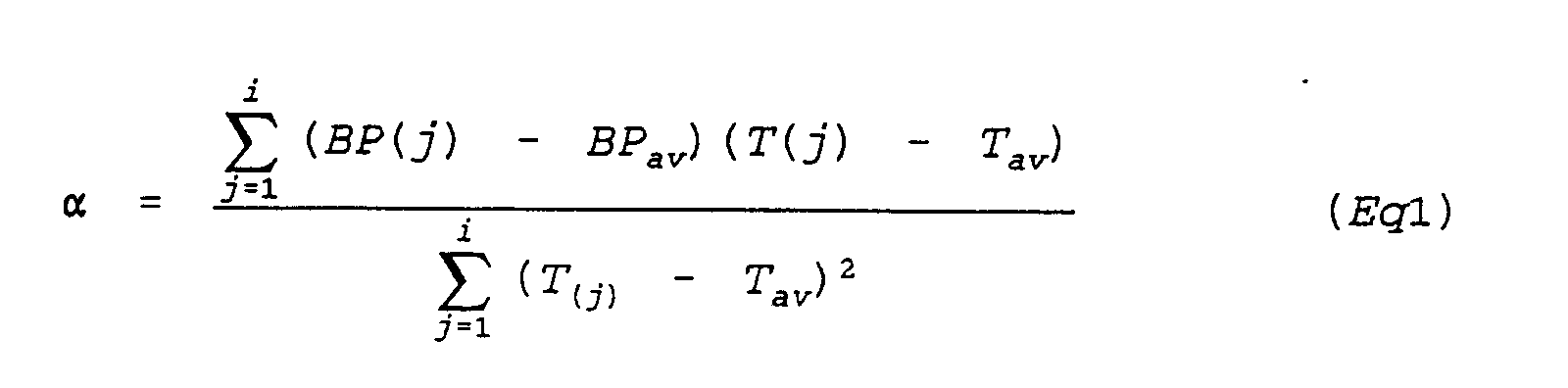
In this case, the BPav is an average of the values in
the ring buffers BP(1) to BP(i), and the Tav is an average of
the values in the ring buffers T(1) to T(i).
On the other hand, β is calculated from the following
equation.
β = BP(i) - α · T(i)
On the other hand, if it is judged in Step S31 that the
maximum calibration point count flag k is set to "1", i.e., the
number of data pieces of the blood pressure values BPt and
pulse wave propagation times Tt1 written in the ring buffers
BP(i) and T(i) has reached the maximum calibration point count
m, α, β are calculated based on the data corresponding to the
maximum calibration point count m in Step S33. In this case
also, α, β are calculated by the least-squares method.
In Step S33, α, β are calculated from the blood
pressure values BPt and pulse wave propagation times Tt1
corresponding to the maximum calibration point count m that is
a count specified by the ring buffer address counter i. The
value α is calculated by an equation indicated in Eq. 2.

In this case, the BPav is an average of the values in
the ring buffers BP(1) to BP(m), and the Tav is an average of
the values in the ring buffers T(1) to T(m).
On the other hand, β is calculated from the following
equation.
β = BP(m) - α · T(m)
As described above, if there are two or more sets of
data, each set of data consisting of a blood pressure value BPt
and a pulse wave propagation time Tt1, temporarily stored in
the ring buffer BP(i), α, β are calculated by the least-squares
method based on such two sets of data.
After the processing in Step S32 or 33 has been
completed, it is judged in Step S34 whether or not the ring
buffer address counter i indicates a count that is equal to the
maximum calibration point count m or more. If it is judged
affirmatively, the ring buffer address counter i is set to "1",
and the α, β calculating subroutine is terminated. From then
on, the values α, β are calculated by the least-squares method
for all the data stored in the ring buffers (for m pieces of
data). If, on the other hand, the ring buffer address counter
i has a count smaller than the maximum calibration point count
m, the subroutine is terminated directly.
As described above, in this embodiment, when a command
for making an initial blood pressure measurement has been
inputted through the key, the blood pressure value BPt is
measured with the cuff 2, and the measured blood pressure value
BPt is displayed. At the same time, the pulse wave propagation
time Tt1 is counted. Immediately thereafter, a measurement of
the pulse wave propagation time Tt is started. The pulse wave
propagation time Tt is consecutively counted, and the pulse
wave propagation time change ΔT is calculated every time the
pulse wave propagation time Tt is counted, and the calculated
pulse wave propagation time change ΔT is compared with the
pulse wave propagation time change threshold ΔTs. When the
pulse wave propagation time change ΔT exceeds the pulse wave
propagation time change threshold ΔTs, not only the blood
pressure value BPt is measured again with the cuff 2, but also
the pulse wave propagation time Tt1 is counted again. Further,
the values α, β specific to a subject are calculated. Then,
the pulse wave propagation time change threshold ΔTs is
calculated from the calculated coefficient α, and the current
pulse wave propagation time change threshold ΔTs is updated.
In this case, the coefficients α, β are calculated based on the
least-squares method from at least two sets of data, each set
of data consisting of a blood pressure value BPt and a pulse
wave propagation time Tt1, which are stored in the past
including the blood pressure value BPt and pulse wave
propagation time Tt1 currently obtained.
Therefore, by judging whether or not the pulse wave
propagation time change ΔT exceeds the pulse wave propagation
time change threshold ΔTs while consecutively counting the
pulse wave propagation time Tt, not only sudden changes in the
blood pressure fluctuation of a subject are monitored, but also
a blood pressure measurement is made using the cuff 2 correctly
at the time of a sudden change in blood pressure fluctuation,
and the pulse wave propagation time change threshold ΔTs is
updated. Therefore, not only burdens given to the subject in
the conventional example can be reduced significantly, but also
blood pressure fluctuations can be monitored with high
accuracy.
It may be noted that pulse wave propagation time
counting processing may be made every heart beat or may be made
in such a manner that the counting processing is executed at a
predetermined time interval or for predetermined heart rates
and an average of the counts is then calculated. By
calculating the average, accurate pulse wave propagation time
counting free from irregularly occurring noise can be
implemented.
The second basic concept of the invention will
hereunder be described.
In a blood pressure monitoring apparatus of the
noninvasive measurement type utilizes pulse wave propagation
velocity (pulse wave propagation time at a predetermined
distance).
The principle of a blood pressure measuring method
based on pulse wave propagation velocity is as follows.
As shown in Fig. 5, the specific point of a pulse wave
on the peripheral blood vessel side appears with a delay with
respect to the specific point of an aortic pulse wave. This
delay time is the pulse wave propagation time.
A pulse wave propagation velocity corresponding to a
pulse wave propagation time at a predetermined distance appears
as a function of the volume elasticity of a blood vessel. The
volume elasticity of a blood vessel increases with increasing
blood pressure, and the blood vessel wall becomes hard, which
in turn increases propagation velocity.
Therefore, blood pressure fluctuations can be
calculated from pulse wave propagation velocity. By
consecutively measuring the pulse wave propagation time, the
blood pressure fluctuations of a subject can be monitored. In
this case, when a pulse wave propagation time change ΔT exceeds
a preset pulse wave propagation time change threshold ΔTs, or
when a heart rate change ΔHR exceeds a cardiovascular dynamic
change threshold ΔHRs equivalent to a preset heart rate change,
or when a rate of change of the amplitude of a pulse wave of a
peripheral blood vessel r1 exceeds a cardiovascular dynamic
change threshold r1s equivalent to a preset rate of change of
the amplitude of a pulse wave of a peripheral blood vessel, or
when a rate of change of the dc component of a pulse wave of a
peripheral blood vessel r2 exceeds a cardiovascular dynamic
change threshold r2s equivalent to a preset rate of change of
the dc component of a pulse wave of a peripheral blood vessel,
then it is judged that a sudden turn for the worse in the blood
pressure fluctuation has occurred on a subject, and a
noninvasive blood pressure measurement using the cuff is made
at such timing.
In this case, the heart rate change ΔHR, the rate of
change of the amplitude of the pulse wave of the peripheral
blood vessel r1, and the rate of change of the dc component of
the pulse wave of the peripheral blood vessel r2 are
cardiovascular dynamic changes, and these changes are more
critical than the pulse wave propagation time change ΔT.
Therefore, these changes can detect even a feeble change in
blood pressure which cannot be detected by the pulse wave
propagation time. As a result, a sudden turn for the worse in
blood pressure fluctuation can be monitored with extremely high
accuracy.
A blood pressure monitoring apparatus, which is an
embodiment of the invention, will now be described with
reference to the drawings.
Fig. 6 is a block diagram showing an exemplary
configuration of the blood pressure monitoring apparatus of the
invention. In Fig. 6, a cuff 102 is designed to be attached to
a brachium or finger of a subject and the inside thereof is
opened or closed with respect to the atmosphere by an exhaust
valve 103. Air is supplied to the cuff 102 by a pressuring
pump 104. A pressure sensor 105 is arranged on the cuff main
body, and the output of the sensor is detected by a cuff
pressure detecting section 106. The output of the cuff
pressure detecting section 106 is converted into a digital
signal by an A/D converter 107 and is received by a CPU
(central processing unit) 101.
A time interval detection reference point detecting
section 108 is provided to detect a timing at which the aortic
blood pressure reaches a bottom value thereof substantially
simultaneously with generation of an ECG R wave. The output of
this detecting section 8 is received by the CPU 101 while
converted into a digital signal by an A/D converter 109. The
time interval detection reference point detecting section 108
can be constructed of electrodes that are attached to the chest
of a subject and an ECG R wave detecting section to which the
electrodes are connected. It may be noted that the time
interval detection reference point detecting section 108 can be
constructed also of a photoelectric pulse wave sensor or
pressure pulse wave sensor for detecting an aortic pulse wave,
and a pulse wave detecting section to which such sensor is
connected.
A photoelectric pulse wave sensor 110 is attached to,
e.g., a finger of a subject to measure pulse waves at
peripheral blood vessels. When the output of the photoelectric
pulse wave sensor 110 is sent to a pulse wave detecting section
111, the pulse wave at a position of the subject to which the
sensor is attached can be detected. The pulse wave detecting
section 111 outputs signals by separating the pulse wave into
an ac component and a dc component. The ac component of the
pulse wave is received by the CPU 101 while converted into a
digital signal by an A/D converter 112. Further, the dc
component of the pulse wave is received by the CPU 101 while
converted into a digital signal by an A/D converter 113.
An input means 114 inputs an initial pulse wave
propagation time change threshold ΔTs, and initial
cardiovascular dynamic change thresholds ΔHRs, r1s, and r2s.
In this case, ΔHRs is a value equivalent to a change in heart
rate; r1s is a value equivalent to the rate of change in the
amplitude of a pulse wave of a peripheral blood vessel; r2s is
a value equivalent to the rate of change in the dc component of
a pulse wave of a peripheral blood vessel. A key 115 is
pressed when blood pressure is measured manually using the cuff
102.
The CPU 101 executes a processing program based on
signals given from the A/D converters 107, 109, 112, 113 and
the key 115, outputs necessary control signals to the discharge
valve 103, the pressure pump 104, and the like, and supplies
the processing result to a display 116. A ROM 117 that is
connected to the CPU 101 has the processing program stored
therein. Further, in a RAM 118 are various registers and data
areas arranged for storing blood pressure measurement data.
The following registers are arranged.
- RT1:
- Register for storing a pulse wave propagation time T1
- RT2:
- Register for storing a pulse wave propagation time T2
- RHR1:
- Register for storing a heart rate HR1
- RHR2:
- Register for storing a heart rate HR2
- RAC1:
- Register for storing an amplitude AC1 of a pulse wave of a peripheral blood vessel
- RAC2:
- Register for storing an amplitude AC2 of a pulse wave of a peripheral blood vessel
- RDC1:
- Register for storing a dc component DC1 of a pulse wave of a peripheral blood vessel
- RDC2:
- Register for storing a dc component DC2 of a pulse wave of a peripheral blood vessel
The cuff 102, the exhaust valve 103, the pressuring
pump 104, the pressure sensor 105, the cuff pressure detecting
section 106, and the A/D converter 107 constitute a blood
pressure measuring means. The RAM 118 corresponds to a storage
means. The time interval detection reference point detecting
section 108 and the A/D converter 109 constitute a time
interval detection reference point detecting means. The
photoelectric pulse wave sensor 110, the pulse wave detecting
section 111, and the A/D converters 112, 113 constitute a pulse
wave detecting means. The CPU 101 corresponds to a pulse wave
propagation time counting means, a pulse wave propagation time
change calculating means, a cardiovascular dynamic change
calculating means, a first judging means, a second judging
means, and a control means.
Then, an operation of the thus constructed blood
pressure monitoring apparatus will be described.
Fig. 7 is a flowchart showing an operation of the blood
pressure monitoring apparatus.
First, in Step S1, the pulse wave propagation time
change threshold ΔTs, the cardiovascular dynamic change
thresholds ΔHRs, r1s, and r2s are inputted from the input means
114 and written to the RAM 118. It may be noted that these
thresholds ΔTs, ΔHRs, r1s, and r2s are preset by considering the
weight, height, etc. of a subject.
After the respective thresholds have been written to
the RAM 118, it is judged in Step S2 whether or not an input is
given through the key 115. If it is judged affirmatively, the
exhasut valve 103 and the pressuring pump 104 are controlled by
the CPU 1 in Step S3, and a blood pressure measurement is made
on a subject using the cuff 102. Data received from the A/D
converter 107 is processed internally by the CPU 101, and a
blood pressure value BP measured by an oscillometric method is
written to the RAM 118.
After the blood pressure value BP has been written,
Step S4 is executed. That is, in Step S4, the pulse wave
propagation time T2 stored in the register RT2 is moved to the
register RT1; the heart rate HR2 stored in the register RHR2 is
moved to the register RHR1; the amplitude AC2 of the pulse wave
stored in the register RAC2 is moved to the register RAC1; and
the dc component DC2 of the pulse wave stored in the register
RDC2 is moved to the register RDC1. In this case, if the pulse
wave propagation time T2 is not counted, the operation of
moving the data to the registers RT1, RHR1, RAC1, and RDC1 is not
actually performed. After the data have been moved from one
register to another, the previously measured blood pressure
value BP is displayed on the display 16 in Step S5. Then, Step
S2 will be executed.
In Step S2, whether or not an input has been made
through the key is judged again. If it is judged negatively,
the pulse wave propagation time T2 equivalent to a time
interval from a timing at which an aortic pulse wave reaches
the bottom value thereof substantially simultaneously with
generation of an ECG R wave to a timing at which the pulse wave
at a peripheral blood vessel reaches the bottom value thereof
based on data from the A/D converters 109, 112, and the
measured value is stored in the register RT2 of the RAM 118 in
Step S6. Further, the heart rate and the amplitude and dc
component of the pulse wave at the peripheral blood vessel are
measured, and the measured values are stored in the registers
RHR2, RAC2, and RDC2 of the RAM 118.
Then, in Step S7, it is judged whether or not the data
of the pulse wave propagation time T1 is present. If the data
is present, the pulse wave propagation time change ΔT, the
heart rate change ΔHR, the pulse wave amplitude change rate r1,
and the pulse wave dc component change rate r2 are calculated
in Step S8. That is, the pulse wave propagation time change ΔT
is calculated by the following equation.
ΔT = | T2 - T1 |
Further, the heart rate change ΔHR, the pulse wave
amplitude change rate r1, and the pulse wave dc component
change rate r2 are calculated by the following equations.
ΔHR = | HR2 - HR1 | r1 = | (AC2 - AC1 ) / AC1 | r2 = | (DC2 - DC1 ) / DC1 |
After the pulse wave propagation time change ΔT, the
heart rate change ΔHR, the pulse wave amplitude change rate r1,
and the pulse wave dc component change rate r2 have been
calculated, Step S9 will be executed. That is, in Step S9, it
is judged whether or not the pulse wave propagation time change
ΔT calculated in Step S8 exceeds the preset pulse wave
propagation time change threshold ΔTs; it is judged whether or
not the heart rate change ΔHR calculated in Step S8 exceeds the
value ΔHRS equivalent to the preset heart rate change; it is
judged whether or not the pulse wave amplitude change rate r1
calculated in Step S8 exceeds the value r1s equivalent to the
preset rate of change of the amplitude of the pulse wave at the
peripheral blood vessel; and it is judged whether or not the
pulse wave dc component change rate r2 calculated in Step S8
exceeds the value r2s equivalent to the preset rate of change
of the dc component of the pulse wave at the peripheral blood
vessel. That is, it is judged whether or not ΔT > ΔTs, ΔHR >
ΔHRs, r1 > r1s, and r2 > r2s are satisfied. If none of the above
inequalities is satisfied, then, a series of operation is
repeated starting at Step S2.
On the other hand, if any one of the inequalities ΔT >
ΔTs, ΔHR > ΔHRs, r1 > r1s, and r2 > r2s is satisfied, it is
assumed that a sudden turn for the worse such as a shock has
occurred in the blood pressure fluctuation of the subject, Step
S3 will be executed. In Step S3, in order to take care of the
sudden turn for the worse in the blood pressure fluctuation of
the subject, a blood pressure measurement is made using the
cuff 102, and the measured value BP is written to a data area
in the RAM 118. Then, in Step S4, the pulse wave propagation
time T2 stored in the register RT2 is moved to the register RT1;
the heart rate HR2 stored in the register RHR2 is moved to the
register RHR1; the amplitude AC2 of the pulse wave stored in the
register RAC2 is moved to the register RAC1; and the dc
component DC2 of the pulse wave stored in the register RDC2 is
moved to the register RDC1. Then, in Step S5, the blood
pressure value BP measured in Step S3 is displayed on the
display 116. Step S2 will thereafter be executed.
As described in the foregoing, this embodiment is
characterized as constantly measuring the pulse wave
propagation time and not only judging whether or not the pulse
wave propagation time change ΔT exceeds the pulse wave
propagation time change threshold ΔTs but also judging whether
or not the cardiovascular dynamic changes ΔHR, r1, r2 exceed the
thresholds thereof ΔHRs, r1s, r2s, so that a sudden turn for the
worse in the blood pressure fluctuation of a subject can be
monitored and a blood pressure measurement using the cuff 2 is
made reliably if any one of the values exceeds the threshold
thereof. Therefore, the burden given to the subject in the
past can be reduced. In addition, this embodiment is also
characterized as allowing a feeble blood pressure fluctuation
that cannot be detected by the pulse wave propagation time
change to be detected by the cardiovascular dynamic change.
Therefore, a sudden turn for the worse in the blood pressure
fluctuation of the subject can be monitored more reliably.
It should be noted that pulse wave propagation time
counting processing may be made every heart beat or may be made
in such a manner that the processing is executed at a
predetermined time interval or for predetermined heart rates
and an average of the counts can then be calculated. This
technique of calculating the average allows accurate pulse wave
propagation time counting free from irregularly occurring noise
to be made.
According to the blood pressure monitoring apparatus of
the present invention, a pulse wave propagation time change is
calculated every time a pulse wave propagation time is counted
consecutively, and the calculated pulse wave propagation time
change is compared with a pulse wave propagation time change
threshold; if the pulse wave propagation time change exceeds
the pulse wave propagation time change threshold, a blood
pressure measurement is made using a cuff and a pulse wave
propagation time is counted; in this case, if there are at
least two sets of data, each set of data consisting of a blood
pressure value and a pulse wave propagation time obtained in a
blood pressure measurement, including those data stored in the
past, coefficients specific to a subject are calculated based
on the least-squares method from the respective two sets of
data; further, the pulse wave propagation time change threshold
is calculated from a calculated coefficient specific to the
subject; and the current pulse wave propagation time change
threshold is updated. Therefore, it is no longer necessary to
measure blood pressure using a cuff at a short cycle as in the
conventional example, nor is it necessary to make invasive
blood pressure measurements. As a result, burdens given to a
subject can be reduced to a significant degree, which in turn
allows blood pressure fluctuations to be monitored with high
accuracy.
As described in the foregoing, the blood pressure
monitoring apparatuses of the present invention are not only
judging whether or not the pulse wave propagation time change
exceeds the preset pulse wave propagation time change
threshold, but also judging whether or not the cardiovascular
dynamic change, i.e., the heart rate change, the rate of change
of the amplitude of the pulse wave at the peripheral blood
vessel, or the rate of change of the dc component of the pulse
wave at the peripheral blood vessel, exceed the preset
cardiovascular dynamic change thresholds thereof and starting
a blood pressure measurement for the subject if any one of the
changes is judged to exceed the threshold thereof. Therefore,
the burden given to the subject in the past can be reduced. In
addition, the blood pressure monitoring apparatuses of the
present invention are also characterized as allowing a feeble
blood pressure fluctuation that cannot be detected by the pulse
wave propagation time change to be detected by the
cardiovascular dynamic change. Therefore, a sudden turn for
the worse in the blood pressure fluctuation of the subject can
be monitored more reliably.
Claims (10)
- A blood pressure monitoring apparatus comprising:blood pressure measuring means for measuring blood pressure using a cuff;storage means for storing a pulse wave propagation time change threshold and a cardiovascular dynamic change threshold, both thresholds being inputted from an external means;time interval detection reference point detecting means for detecting a time interval detection reference point on a pulse wave at an aorta of a body;pulse wave detecting means for detecting a pulse wave at a peripheral blood vessel appearing with a time delay with respect to said pulse wave at said aorta;pulse wave propagation time counting means for counting a pulse wave propagation time based on detected outputs from said time interval detection reference point detecting means and said pulse wave detecting means;pulse wave propagation time change calculating means for calculating a pulse wave propagation time change from said two pulse wave propagation times counted by said pulse wave propagation time counting means;main judgement means for judging whether or not a condition of an subject is changed on the basis of a result of said pulse wave propagation time change calculating means; andmain control means for controlling said blood pressure measuring means and for measuring blood pressure of a subject using said cuff in accordance with a result of said judging means.
- A blood pressure monitoring apparatus as claimed in claim 1, further comprising:first logic operation means for calculating coefficients specific to a subject from at least two blood pressure values stored in the blood pressure value storage means and from the pulse wave propagation times stored in the pulse wave propagation time storage means corresponding to the each blood pressure values, the coefficients allowing equations expressing a relationship between blood pressure and pulse wave propagation time to be established; andsecond logic operation means for updating a pulse wave propagation time change threshold stored in the threshold storage means by dividing a blood pressure change threshold read from the threshold storage means by a calculated coefficient specific to the subject,
wherein said judgement means judges whether or not the calculated pulse wave propagation time change exceeds the pulse wave propagation time change threshold read from the threshold storage means, and saic control means measures blood pressure of the subject using the cuff by controlling the blood pressure measuring means and controlling the pulse wave propagation time change threshold updating operation when it is judged that the pulse wave propagation time change exceeds the pulse wave propagation time change threshold. - A blood pressure monitoring apparatus according to claim 2, wherein the first logic operation means calculates the coefficients specific to the subject by a least-squares method using at least two blood pressure values stored in the blood pressure value storage means and the pulse wave propagation times stored in the pulse wave propagation time storage means corresponding to the each blood pressure values, the coefficients being equivalent to a single regression coefficient and a coefficient term when the relationship between blood pressure and pulse wave propagation time is expressed in the form of a single regression line.
- A blood pressure monitoring apparatus according to claim 1, further comprising:cardiovascular dynamic change calculating means for calculating a cardiovascular dynamic change from said time interval detection reference point or said pulse wave at said peripheral blood pressure; andauxiliary judging means for judging whether or not said cardiovascular dynamic change calculated by said cardiovascular dynamic change calculating means exceeds said cardiovascular dynamic change threshold stored in said storage means,
wherein said main judging means for judging whether or not said pulse wave propagation time change calculated by said pulse wave propagation time change calculating means exceeds said pulse wave propagation time change threshold stored in said storage means, and said main control means for controlling said blood pressure measuring means and for measuring blood pressure of a subject using said cuff if it is judged that said pulse wave propagation time change exceeds said pulse wave propagation time change threshold or if it is judged that said cardiovascular dynamic change exceeds said cardiovascular dynamic change threshold. - A blood pressure monitoring apparatus according to claim 4, wherein said storage means stores a cardiovascular dynamic change threshold equivalent to a heart rate change, said cardiovascular dynamic change calculating means calculates a heart rate change based on said time interval detection reference point detected by said time interval detection reference point detecting means, and said second judging means judges whether or not said heart rate change calculated by said cardiovascular dynamic change calculating means exceeds said cardiovascular dynamic change threshold equivalent to said heart rate change stored in said storage means.
- A blood pressure monitoring apparatus according to claim 4, wherein said storage means stores a cardiovascular dynamic change threshold equivalent to a rate of change of an amplitude of a pulse wave at a peripheral blood vessel; said cardiovascular dynamic change calculating means calculates said rate of change of said amplitude of said pulse wave, which is a chronological rate of change of said amplitude of said pulse wave based on said pulse wave at said peripheral blood vessel detected by said pulse wave detecting means; and said second judging means judges whether or not said rate of change of said amplitude of said pulse wave calculated by said cardiovascular dynamic change calculating means exceeds said cardiovascular dynamic change threshold equivalent to said rate of change of said amplitude of said pulse wave of said peripheral blood vessel stored in said storage means.
- A blood pressure monitoring apparatus according to claim 4, wherein said storage means stores a cardiovascular dynamic change threshold equivalent to a rate of change of a dc component of a pulse wave of a peripheral blood vessel; said cardiovascular dynamic change calculating means calculates said rate of change of said dc component of said pulse wave, which is a chronological rate of change of said dc component of said pulse wave based on said pulse wave at said peripheral blood vessel detected by said pulse wave detecting means; and said second judging means judges whether or not said rate of change of said dc component of said pulse wave calculated by said cardiovascular dynamic change calculating means exceeds said cardiovascular dynamic change threshold equivalent to said rate of change of said dc component of said pulse wave of said peripheral blood vessel stored in said storage means.
- A blood pressure monitoring apparatus according to claim 4, wherein said storage means stores cardiovascular dynamic change thresholds respectively equivalent to a heart rate change, a rate of change of an amplitude of a pulse wave of a peripheral blood vessel, and a rate of change of a dc component of a pulse wave of a peripheral blood vessel; said cardiovascular dynamic change calculating means calculates not only said heart rate change based on said time interval detection reference point detected by said time interval detection reference point detecting means, but also said rate of change of said amplitude of said pulse wave, which is a chronological rate of change of said amplitude of said pulse wave and said rate of change of said dc component of said pulse wave, which is a chronological rate of change of said dc component of said pulse wave, based on said pulse wave at said peripheral blood vessel detected by said pulse wave detecting means; said second judging means judges whether or not said heart rate change calculated by said cardiovascular dynamic change calculating means exceeds said cardiovascular dynamic change threshold equivalent to said heart rate change stored in said storage means, whether or not said rate of change of said amplitude of said pulse wave calculated by said cardiovascular dynamic change calculating means exceeds said cardiovascular dynamic change threshold equivalent to said rate of change of said amplitude of said pulse wave of said peripheral blood vessel stored in said storage means, and whether or not said rate of change of said dc component of said pulse wave calculated by said cardiovascular dynamic change calculating means exceeds said cardiovascular dynamic change threshold equivalent to said rate of change of said dc component of said peripheral blood vessel stored in said storage means; and said control means controls said blood pressure measuring means and measures blood pressure of a subject using said cuff if it is judged that said heart rate change exceeds said cardiovascular dynamic change threshold equivalent to said heart rate change, if it is judged that said rate of change of said amplitude of said pulse wave exceeds said cardiovascular dynamic change threshold equivalent to said rate of change of said amplitude of said pulse wave of said peripheral blood vessel, or if it is judged that said rate of change of said dc component of said pulse wave exceeds said cardiovascular dynamic change threshold equivalent to said rate of change of said dc component of said pulse wave of said peripheral blood vessel.
- A blood pressure monitoring method comprising said steps of:measuring blood pressure using cuff;storing a pulse wave propagation time change threshold and a cardiovascular dynamic change threshold, both thresholds being inputted from an external means;detecting a time interval detection reference point on a pulse wave at an aorta of a body;detecting a pulse wave at a peripheral blood vessel appearing with a time delay with respect to said pulse wave at said aorta;counting a pulse wave propagation time based on detected outputs from said time interval detection reference point and said pulse wave;calculating a pulse wave propagation time change from said two pulse wave propagation times counted;calculating a cardiovascular dynamic change from said time interval detection reference point or said pulse wave at said peripheral blood pressure;judging whether or not said pulse wave propagation time change calculated exceeds said pulse wave propagation time change threshold stored;judging whether or not said cardiovascular dynamic change exceeds said cardiovascular dynamic change threshold;
andmeasuring blood pressure of a subject using said cuff if it is judged that said pulse wave propagation time change exceeds said pulse wave propagation time change threshold or if it is judged that said cardiovascular dynamic change exceeds said cardiovascular dynamic change threshold. - A blood pressure monitoring method comprising said steps of:measuring blood pressure using a cuff;storing a blood pressure value;storing a pulse wave propagation time change threshold and a blood pressure change threshold that are inputted from external sources;detecting a time interval detection reference point on a pulse wave at an aorta of a body;detecting a pulse wave at a peripheral blood vessel appearing with a time delay with respect to the pulse wave at the aorta;counting a pulse wave propagation time based on detected outputs of the time interval detection reference point and the pulse wave;storing a pulse wave propagation time counted when the blood pressure has been measured;calculating a pulse wave propagation time change from two pulse wave propagation times counted;calculating coefficients specific to a subject from at least two blood pressure values stored and from the pulse wave propagation times stored corresponding to the each blood pressure values, the coefficients allowing equations expressing a relationship between blood pressure and pulse wave propagation time to be established;updating a pulse wave propagation time change threshold stored by dividing a blood pressure change threshold read by a calculated coefficient specific to the subject;judging whether or not the calculated pulse wave propagation time change exceeds the pulse wave propagation time change threshold read; andmeasuring blood pressure of the subject using the cuff by controlling the blood pressure measuring means and controlling the pulse wave propagation time change threshold updating operation when it is judged that the pulse wave propagation time change exceeds the pulse wave propagation time change threshold.
Priority Applications (1)
| Application Number | Priority Date | Filing Date | Title |
|---|---|---|---|
| EP97107225A EP0875200A1 (en) | 1997-04-30 | 1997-04-30 | Blood pressure monitoring apparatus |
Applications Claiming Priority (1)
| Application Number | Priority Date | Filing Date | Title |
|---|---|---|---|
| EP97107225A EP0875200A1 (en) | 1997-04-30 | 1997-04-30 | Blood pressure monitoring apparatus |
Publications (1)
| Publication Number | Publication Date |
|---|---|
| EP0875200A1 true EP0875200A1 (en) | 1998-11-04 |
Family
ID=8226757
Family Applications (1)
| Application Number | Title | Priority Date | Filing Date |
|---|---|---|---|
| EP97107225A Withdrawn EP0875200A1 (en) | 1997-04-30 | 1997-04-30 | Blood pressure monitoring apparatus |
Country Status (1)
| Country | Link |
|---|---|
| EP (1) | EP0875200A1 (en) |
Cited By (8)
| Publication number | Priority date | Publication date | Assignee | Title |
|---|---|---|---|---|
| US6599251B2 (en) | 2000-01-26 | 2003-07-29 | Vsm Medtech Ltd. | Continuous non-invasive blood pressure monitoring method and apparatus |
| US6893401B2 (en) | 2001-07-27 | 2005-05-17 | Vsm Medtech Ltd. | Continuous non-invasive blood pressure monitoring method and apparatus |
| EP1568314A1 (en) * | 2004-02-24 | 2005-08-31 | Omron Healthcare Co., Ltd. | Blood pressure measurement apparatus and method |
| WO2007101431A1 (en) | 2006-03-07 | 2007-09-13 | Fresenius Medical Care Deutschland Gmbh | Dialysis appliance with measuring means for recording blood pressure, and method for determining the blood pressure, and a storage medium for use in a dialysis appliance |
| EP2193745A1 (en) * | 2008-12-04 | 2010-06-09 | Müller & Sebastiani Elektronik GmbH | Long term blood pressure measuring device |
| US20110230729A1 (en) * | 2007-08-09 | 2011-09-22 | Omron Healthcare Co., Ltd. | Blood pressure measurement device for measuring at appropriate timing |
| US9408542B1 (en) | 2010-07-22 | 2016-08-09 | Masimo Corporation | Non-invasive blood pressure measurement system |
| WO2022179351A1 (en) * | 2021-02-26 | 2022-09-01 | 华为技术有限公司 | Blood pressure monitoring method and apparatus, and wearable device |
Citations (6)
| Publication number | Priority date | Publication date | Assignee | Title |
|---|---|---|---|---|
| US5033472A (en) * | 1989-02-23 | 1991-07-23 | Nihon Kohden Corp. | Method of and apparatus for analyzing propagation of arterial pulse waves through the circulatory system |
| EP0498281A1 (en) * | 1991-01-31 | 1992-08-12 | Sankyo Company Limited | Measurement of transmission velocity of pulse wave |
| US5199438A (en) * | 1989-09-27 | 1993-04-06 | Atp Advanced Technologies Limited | Measurement of cardiac performance |
| US5339822A (en) * | 1991-05-07 | 1994-08-23 | Protocol Systems, Inc. | Method of validating physiologic events resulting from a heartbeat |
| EP0698370A2 (en) * | 1994-08-23 | 1996-02-28 | Colin Corporation | Blood-pressure monitor apparatus |
| US5564427A (en) * | 1994-03-30 | 1996-10-15 | Nihon Kohden Corporation | Blood pressure monitoring system |
-
1997
- 1997-04-30 EP EP97107225A patent/EP0875200A1/en not_active Withdrawn
Patent Citations (6)
| Publication number | Priority date | Publication date | Assignee | Title |
|---|---|---|---|---|
| US5033472A (en) * | 1989-02-23 | 1991-07-23 | Nihon Kohden Corp. | Method of and apparatus for analyzing propagation of arterial pulse waves through the circulatory system |
| US5199438A (en) * | 1989-09-27 | 1993-04-06 | Atp Advanced Technologies Limited | Measurement of cardiac performance |
| EP0498281A1 (en) * | 1991-01-31 | 1992-08-12 | Sankyo Company Limited | Measurement of transmission velocity of pulse wave |
| US5339822A (en) * | 1991-05-07 | 1994-08-23 | Protocol Systems, Inc. | Method of validating physiologic events resulting from a heartbeat |
| US5564427A (en) * | 1994-03-30 | 1996-10-15 | Nihon Kohden Corporation | Blood pressure monitoring system |
| EP0698370A2 (en) * | 1994-08-23 | 1996-02-28 | Colin Corporation | Blood-pressure monitor apparatus |
Cited By (11)
| Publication number | Priority date | Publication date | Assignee | Title |
|---|---|---|---|---|
| US6599251B2 (en) | 2000-01-26 | 2003-07-29 | Vsm Medtech Ltd. | Continuous non-invasive blood pressure monitoring method and apparatus |
| US6893401B2 (en) | 2001-07-27 | 2005-05-17 | Vsm Medtech Ltd. | Continuous non-invasive blood pressure monitoring method and apparatus |
| EP1568314A1 (en) * | 2004-02-24 | 2005-08-31 | Omron Healthcare Co., Ltd. | Blood pressure measurement apparatus and method |
| CN100399982C (en) * | 2004-02-24 | 2008-07-09 | 苅尾七臣 | Blood pressure measurement apparatus and method |
| WO2007101431A1 (en) | 2006-03-07 | 2007-09-13 | Fresenius Medical Care Deutschland Gmbh | Dialysis appliance with measuring means for recording blood pressure, and method for determining the blood pressure, and a storage medium for use in a dialysis appliance |
| US8303807B2 (en) | 2006-03-07 | 2012-11-06 | Fresenius Medical Care Deutschland Gmbh | Dialyser with measuring devices for monitoring the blood pressure, method of determining the blood pressure and a storage medium for use in a dialyser |
| US20110230729A1 (en) * | 2007-08-09 | 2011-09-22 | Omron Healthcare Co., Ltd. | Blood pressure measurement device for measuring at appropriate timing |
| US9060694B2 (en) * | 2007-08-09 | 2015-06-23 | Omron Healthcare Co., Ltd. | Blood pressure measurement device for measuring at appropriate timing |
| EP2193745A1 (en) * | 2008-12-04 | 2010-06-09 | Müller & Sebastiani Elektronik GmbH | Long term blood pressure measuring device |
| US9408542B1 (en) | 2010-07-22 | 2016-08-09 | Masimo Corporation | Non-invasive blood pressure measurement system |
| WO2022179351A1 (en) * | 2021-02-26 | 2022-09-01 | 华为技术有限公司 | Blood pressure monitoring method and apparatus, and wearable device |
Similar Documents
| Publication | Publication Date | Title |
|---|---|---|
| US5755669A (en) | Blood pressure monitoring apparatus | |
| US6083171A (en) | Blood pressure monitoring apparatus | |
| US6652466B2 (en) | Blood flow volume measurement method and vital sign monitoring apparatus | |
| JP2764702B2 (en) | Blood pressure monitoring device | |
| US4860759A (en) | Vital signs monitor | |
| US6547740B2 (en) | Blood pressure monitoring apparatus | |
| US5743263A (en) | Pulse Oximeter using a virtual trigger for heart rate synchronization | |
| US5682898A (en) | Respiration rate measuring apparatus | |
| EP1387635B1 (en) | Non invasive measurement of blood pressure | |
| EP1641389B1 (en) | Apparatus and method for measuring hemodynamic parameters | |
| US4408614A (en) | Blood pressure measurement with Korotkov sound artifact information detection and rejection | |
| EP0852126A2 (en) | Blood pressure monitoring apparatus | |
| US20030220577A1 (en) | Methods and systems for distal recording of phonocardiographic signals | |
| US8282567B2 (en) | Method and system for determination of pulse rate | |
| JP2001504362A (en) | Non-destructive blood pressure measurement device without pressurized zone | |
| EP0698370B1 (en) | Blood-pressure monitor apparatus | |
| KR20090052442A (en) | Non-invasive blood pressure measuring method and device | |
| EP1203558A2 (en) | Superior-and-inferior-limb blood-pressure index measuring apparatus | |
| US4105020A (en) | Blood pressure and pulse rate measuring apparatus | |
| EP0875200A1 (en) | Blood pressure monitoring apparatus | |
| US6129677A (en) | Non-invasive heart monitoring apparatus and method | |
| JP3023505B2 (en) | Blood pressure monitoring device | |
| JPH0375169B2 (en) | ||
| JPH0866377A (en) | Multi-functional sphygmomanometer | |
| GB2456947A (en) | Non invasive determination of stroke volume based on incident wave suprasystolic blood pressure amplitude |
Legal Events
| Date | Code | Title | Description |
|---|---|---|---|
| PUAI | Public reference made under article 153(3) epc to a published international application that has entered the european phase |
Free format text: ORIGINAL CODE: 0009012 |
|
| 17P | Request for examination filed |
Effective date: 19980105 |
|
| AK | Designated contracting states |
Kind code of ref document: A1 Designated state(s): CH DE FR GB IT LI NL SE |
|
| AKX | Designation fees paid |
Free format text: CH DE FR GB IT LI NL SE |
|
| 17Q | First examination report despatched |
Effective date: 20020726 |
|
| GRAP | Despatch of communication of intention to grant a patent |
Free format text: ORIGINAL CODE: EPIDOSNIGR1 |
|
| STAA | Information on the status of an ep patent application or granted ep patent |
Free format text: STATUS: THE APPLICATION IS DEEMED TO BE WITHDRAWN |
|
| 18D | Application deemed to be withdrawn |
Effective date: 20041015 |