EP0876302B1 - Anlage zum beseitigen von fetten und ölen - Google Patents
Anlage zum beseitigen von fetten und ölen Download PDFInfo
- Publication number
- EP0876302B1 EP0876302B1 EP19960942222 EP96942222A EP0876302B1 EP 0876302 B1 EP0876302 B1 EP 0876302B1 EP 19960942222 EP19960942222 EP 19960942222 EP 96942222 A EP96942222 A EP 96942222A EP 0876302 B1 EP0876302 B1 EP 0876302B1
- Authority
- EP
- European Patent Office
- Prior art keywords
- container
- container chamber
- fat
- oil
- pipe
- Prior art date
- Legal status (The legal status is an assumption and is not a legal conclusion. Google has not performed a legal analysis and makes no representation as to the accuracy of the status listed.)
- Expired - Lifetime
Links
Images

Classifications
-
- C—CHEMISTRY; METALLURGY
- C02—TREATMENT OF WATER, WASTE WATER, SEWAGE, OR SLUDGE
- C02F—TREATMENT OF WATER, WASTE WATER, SEWAGE, OR SLUDGE
- C02F3/00—Biological treatment of water, waste water, or sewage
- C02F3/34—Biological treatment of water, waste water, or sewage characterised by the microorganisms used
- C02F3/343—Biological treatment of water, waste water, or sewage characterised by the microorganisms used for digestion of grease, fat, oil
-
- B—PERFORMING OPERATIONS; TRANSPORTING
- B01—PHYSICAL OR CHEMICAL PROCESSES OR APPARATUS IN GENERAL
- B01D—SEPARATION
- B01D17/00—Separation of liquids, not provided for elsewhere, e.g. by thermal diffusion
-
- B—PERFORMING OPERATIONS; TRANSPORTING
- B01—PHYSICAL OR CHEMICAL PROCESSES OR APPARATUS IN GENERAL
- B01D—SEPARATION
- B01D17/00—Separation of liquids, not provided for elsewhere, e.g. by thermal diffusion
- B01D17/02—Separation of non-miscible liquids
- B01D17/0208—Separation of non-miscible liquids by sedimentation
- B01D17/0211—Separation of non-miscible liquids by sedimentation with baffles
-
- B—PERFORMING OPERATIONS; TRANSPORTING
- B01—PHYSICAL OR CHEMICAL PROCESSES OR APPARATUS IN GENERAL
- B01D—SEPARATION
- B01D17/00—Separation of liquids, not provided for elsewhere, e.g. by thermal diffusion
- B01D17/02—Separation of non-miscible liquids
- B01D17/04—Breaking emulsions
- B01D17/041—Breaking emulsions with moving devices
-
- B—PERFORMING OPERATIONS; TRANSPORTING
- B01—PHYSICAL OR CHEMICAL PROCESSES OR APPARATUS IN GENERAL
- B01D—SEPARATION
- B01D17/00—Separation of liquids, not provided for elsewhere, e.g. by thermal diffusion
- B01D17/12—Auxiliary equipment particularly adapted for use with liquid-separating apparatus, e.g. control circuits
-
- B—PERFORMING OPERATIONS; TRANSPORTING
- B01—PHYSICAL OR CHEMICAL PROCESSES OR APPARATUS IN GENERAL
- B01D—SEPARATION
- B01D21/00—Separation of suspended solid particles from liquids by sedimentation
- B01D21/003—Sedimentation tanks provided with a plurality of compartments separated by a partition wall
-
- B—PERFORMING OPERATIONS; TRANSPORTING
- B01—PHYSICAL OR CHEMICAL PROCESSES OR APPARATUS IN GENERAL
- B01D—SEPARATION
- B01D2221/00—Applications of separation devices
- B01D2221/02—Small separation devices for domestic application, e.g. for canteens, industrial kitchen, washing machines
-
- C—CHEMISTRY; METALLURGY
- C02—TREATMENT OF WATER, WASTE WATER, SEWAGE, OR SLUDGE
- C02F—TREATMENT OF WATER, WASTE WATER, SEWAGE, OR SLUDGE
- C02F3/00—Biological treatment of water, waste water, or sewage
- C02F3/02—Aerobic processes
- C02F3/08—Aerobic processes using moving contact bodies
- C02F3/082—Rotating biological contactors
-
- Y—GENERAL TAGGING OF NEW TECHNOLOGICAL DEVELOPMENTS; GENERAL TAGGING OF CROSS-SECTIONAL TECHNOLOGIES SPANNING OVER SEVERAL SECTIONS OF THE IPC; TECHNICAL SUBJECTS COVERED BY FORMER USPC CROSS-REFERENCE ART COLLECTIONS [XRACs] AND DIGESTS
- Y02—TECHNOLOGIES OR APPLICATIONS FOR MITIGATION OR ADAPTATION AGAINST CLIMATE CHANGE
- Y02W—CLIMATE CHANGE MITIGATION TECHNOLOGIES RELATED TO WASTEWATER TREATMENT OR WASTE MANAGEMENT
- Y02W10/00—Technologies for wastewater treatment
- Y02W10/10—Biological treatment of water, waste water, or sewage
Definitions
- the present invention relates generally to a plant for the removal of fats and oils, using special fat and oil degrading microorganisms come.
- the system can be used for simultaneous separation and removal of fats and oils in waste water.
- Fats and oils can be of different types, for example mineral, synthetic or organic.
- the organic ones are of particular interest here Fats and oils, such as those found in hotels, restaurants and other commercial kitchens accumulate in waste water.
- the plant can also be used for waste water from food processors Companies of all kinds, such as for slaughterhouses and butchers be conceived.
- a conventional grease separator should be emptied approximately every two to four weeks cleaned, for which the operator of the system is responsible.
- Fat separators in butchers should be at least once a week or at the latest when the fat storage volume is filled getting cleaned.
- Grease traps in kitchen businesses should usually all Be emptied for 14 days. The amount of waste water and the quality of the waste water fluctuate however, even among kitchen businesses with the same number of meals. Studies have shown that because of the diversity of the dishes and their Preparation of the fat content in the wastewater of a hospital kitchen that produces 1,000 meals a day, on average, for example, is about 500 mg / l while in a troop kitchen is around 1,500 mg / l, i.e. three times as much.
- the system for the removal of fats and oils is optionally available as an additional system existing fat separator system is thought to continuously increase the fat separated in it eliminate, or as a separate system for the operation of a central disposal station for Waste fats and oils in which large amounts of fat separator contents are made regularly pumped out fat separators can be treated.
- the heart of the system is a container room with a liquid medium in it, in which a microbiological module is present is that includes a carrier material that contains fat and oil degrading microorganisms is populated, a metering device allowing this container space and thus supply the microorganisms in it with fat and oil.
- the microorganisms then degrade the fat and oil, which causes the pH in the liquid medium of the container space is lowered. It is important that the boundary conditions can be observed for a high activity of the microorganisms used. In addition to the metered supply of fat and oil, the microorganisms also need if necessary Air and nutrient solution supplied.
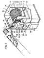
- Such a system for the removal of fats and oils consists, as here, as an example in Figure 1 shown from a square container 1.
- This can be made of chrome steel or be made of plastic, whereby polypropylene is particularly suitable because it is resistant is against fatty acids and even low pH values cannot harm it. So is also no corrosion problems to be expected in the long run.
- the container 1 has in his Inside a container space 9 separated from the partition 3, which contains the microbiological Contains module in the form of a drum 20, and in operation up to the drum axis is filled with a liquid medium.
- the bottom of this container space 9 forms one towards the bottom of the can 11.
- the container 9 in the back of the can 11 has one Drain 12.
- This lattice drum can be inside by additional plastic rods Compartments. It is used to operate the system with carrier materials for grease and oil-degrading microorganisms.
- the carrier materials with the populated on them Microorganisms are alternately contaminated with the drum 20 by the fat Water and medium, the level of which is up to about the middle of the drum shaft 29 enough, and then rotated again through the air above the level. They take oil and fat that is degraded by the microorganisms, as described below becomes.
- a fan 36 with check valve is installed, which Air can be blown into the interior of the container because of the microorganisms used are aerobic and require an air supply.
- the exhaust air is inside the container 1 through a hole present on the top of the overflow pipe 55 at its uppermost position blown, or through a special odor filter, not shown here, to the outside blown.
- the metering device for the fat and oil is as follows in the example shown realized: on the container 1 is an inlet pipe 56 made of acid-resistant plastic for the supplied and degradable oil and fat present, which is inclined into the interior of the container leads and opens there over the container space 9. From the container wall 6 that is Plastic tube 57 is flexible and is on the underside of a plastic tube 58 connected with a larger diameter, inside an Archimedes screw 59 is arranged, which has a shaft made of chrome steel and otherwise also made of acid-resistant Plastic is executed.
- This shaft is driven by a separate motor 60 driven, which is arranged for example at the upper end of the tube 58 as shown here can be.
- the lower end of the tube 58 can now be smell-tight into an existing one Grease separator system are guided, with its lower rim just a little there should be below the level in the grease separator system.
- the pipe 58 is attached depending on the situation by means of a bracket, not shown here. If necessary, the motor 60 can now be switched on, using the Archimedes screw 59 Oil and fat in the pipe 58 upwards, which then via the pipe 57.56 in reaches the container space 9 and is removed there by the microbiological module. The The resulting metabolic products are removed from the container 1 via the line 55 passed out and back into the grease trap.
- a heater in the container space can ensure the activity of the microorganisms 9 can be provided, for example in the form of a heating coil.
- a box 34 with a door attached in which a metering pump is housed. Further In this box there is a container for a nutrient that the microorganisms dosed is supplied.
- a hose or a pipeline 35 leads from this Box 34 from inside the container and there to the drum container 9, where the pipeline opens over the drum 20.
- a Control box attached, in which a programmable electrical control for the Motors 22,60, the fan 36 and the metering pump is housed.
- the facility will above through a cover, not shown here, which is supported on a rubber seal, tightly closed. Nowhere can bad smells come out, because if the Fan 36 is not running, the non-return valve closes the container 1, and if it runs, against the fan air there is no air with odor carriers from the inside out to pour.
- the cover of the system can be hinged, and then it is advantageously supported with gas springs and fixed at the free end by means of buckles can be locked. With such a design, the system can Maintenance purposes easily opened and closed again odor-tight.
- the metering device can Example can be realized by means of a pump and the air supply can be an alternative by using small air bubbles from below into the Container space 9 are blown in by the carrier material for the microorganisms swims. In this case, a rotating drum can be omitted. If necessary, can several plant units can be used in parallel to provide the necessary capacity for to achieve fat and oil degradation.
- the plant for the separation and subsequent removal of fats and oils in waste water additionally works as a grease separator by adding the one with the wastewater separable fats and oils float in the wastewater due to gravity and thus form a layer of fat and odor on the water surface.
- the separated fat and oil is metered into a microbiological module, and the fats and oils are degraded there microbiologically.
- the system still have facilities to accumulate difficult-to-separate particles to make it float, and further the wastewater treated so far can forced to flow through special material, to which the fat and oil particles have a special affinity and soak it up.
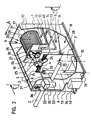
- the plant for separating and subsequent removal of the separated Bold as shown in Figure 2, are described. It consists of one square container 1. This can be made of chrome steel or plastic, whereby polypropylene is particularly suitable because it is resistant to fatty acids and to it even low pH values cannot harm it. This means that there are no corrosion problems in the long term to count.
- the system shown in the picture is one that is dimensioned for a kitchen with a capacity of about 400 meals a day. she is 1.30m long, 0.70m wide and 1.50m high and holds about 900 liters of wastewater.
- the whole Container space 7 of the container 1 between the side wall 6 and the partition 3 is in Operation filled with wastewater.
- the separable fatty substances float in this container part 7 and oil components and form a layer on the water surface.
- This oil and fat layer flows over the edge 4 through the comb 5 during operation, so that primarily the Grease and oil get into the room beyond partition 3.
- the comb 5 stops any floating solids back.
- the fats and oils also flow Waste water via the partition 3.
- the volume flowing over corresponds to that volume flowing through the inlet pipe 2.
- Container space 8 again separates those still floating in the waste water separable fats and oils.
- this container space 8 is installed from above a sealed from the container space 8, separate container space 9 with a Partition 10, which contains a microbiological module in the form of a drum 20.
- the underside of this container space 9 forms a can 11 falling towards the rear.
- the container 9 has a drain 12 in the back of this can 11, which leads into an overflow pipe 13 and via this back into the container 8, the mouth 14 of the overflow pipe 13 a few centimeters above the level of the lower edge of the drain pipe 15 of the Container 1 is arranged.
- the container space 8 has one rear inclined floor 16, which has recesses at the rear corners or is spaced over its entire width from the side wall 17 of the container 1.
- the space 18 below the inclined floor 16 is free here and the drain pipe 15 leads from it through the partition 3 into the container space 7, in this upwards and from there on one Level that is slightly below the level of the inlet pipe 2 to the outside.
- the Container space 7 acts as a sludge trap and sink space for any solids that with the Waste water get into the plant. This accumulated sludge and solids can are drained from time to time via the drain lines 19. If none to drain If there is a further gradient, a pump is connected to the drain line 19. Longitudinally through the container spaces 7 and 8 to the partition 10 of the container 9 there is a drive shaft 21 which is made of stainless steel. It is driven by one Electric motor 22 with angular gear 23.
- a stirring arm 24 is attached in the area of the container space 3 .
- One or more such agitator arms which are aligned with the axis 21 turn, thereby keeping the upper layer of fat, oil and water in the container space 7 constantly on the move. It has been shown that this measure prevents the floating of the Fats and oils on the one hand, and the decrease in solids and sludges on the other hand, is very beneficial.
- a plastic gear 27 is on a reinforcing plate 40 mounted on the partition 10. This engages in an equal size, gear 28 arranged below it.
- This gear wheel 28 has a shaft 29 connected from plastic, which forms the drum axis of a drum 20, which is in Container room 9 is located.
- This drum 20 has a drum disc on both sides 30.31, and these drum disks are along the circumference of the disks with plastic tubes 32 or plastic round rods connected so that a lattice drum 20 is formed is.
- This grid drum can be divided into compartments on the inside by further plastic rods.
- the drum 20 For the operation of the plant, it is filled with carrier materials for microorganisms, such as which will be described later, and the drum 20 then rotates these substrates with the microorganisms then populate alternately with the water contaminated with fat, whose level reaches about the middle of the drum shaft 29, and then through again the air above the level.
- the motor for rotating the drum points for this dimension a grease trap for a kitchen with a capacity of 400 meals a day Power of 370 watts.
- a fan 36 In the side wall 6 is a fan 36 with a check valve built-in, which allows air to be blown into the interior of the container because the microorganisms used are aerobic and require an air supply.
- the exhaust air is by an existing on the top of the drain pipe 15 at its highest point Hole 33 blown into the sewage system, or through a special one, not shown here Blown out odor filter. If the heat supplied with the fat and oil as well the ambient heat is insufficient to maintain a sufficient temperature for the activity of the Ensuring microorganisms can be a heating device for the container rooms 7, 8 and in particular 9 are provided, for example in the form of a heating coil. Below the Motors 22 is a box 34 with door attached, in which a metering pump is housed. This box also contains a container for a nutrient that Microorganisms are fed in doses.
- a hose or a pipeline leads to this 35 from this box into the interior of the container and there to the drum container 9, where the Pipeline 35 opens over the drum 20.
- a control box in which a programmable electrical Control for the motor 22, the fan 36 and the metering pump is housed.
- the facility is up here by one Lid not shown, which rests on a rubber seal, tightly closed. Nowhere can bad smells come out, because when the fan 36 is not running, the non-return flap closes the container, and when it is running it can hold the container Fan air no air to flow with odorants from the inside out.
- the lid the system can be designed to be hinged, it then advantageously using gas springs is supported and can be securely closed at the free end by means of buckles. With a Such execution, the system can easily be opened for maintenance purposes and again be sealed odor-tight.
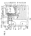
- FIG. 3 shows the system according to FIG. 2 in a sectional view from the long side seen.
- the individual parts are shown here schematically and the figure shows one Section through the system along the plane A-A in Figure 2.
- the system has a cover 46 on which rests on a rubber seal.
- An odor filter 47 is installed in this cover.
- the fan 36 which is built into the container wall 6, is indicated in the top left of the figure is. This blows the air through, for example, a pipe (not shown here) below in a lattice in which a piece of styrofoam fits into this lattice. Blows the Fan, the styrofoam piece is raised and the air can pass through the grille into the Get inside the container.
- the styrofoam piece is on the Vent pipe mouth and closes it.
- the inlet pipe 2 Under the fan 36 is the inlet pipe 2 shown.
- the grease and oil contaminated waste water runs through the inlet pipe 2 into the first one Container space 7, a baffle 61 being arranged in front of the mouth of the inlet pipe is. This prevents a surge of incoming sewage on the surface of the liquid forms a wave in the container space 7 with which excessive water is present the upper edge 4 of the partition 3 would run into the next container space 8.
- the baffle 61 should ensure that the freshly incoming waste water in the container space 7 first the solids and sludge sink and only the previously floated top layer, which in addition to water consists primarily of fat and oil, over the top edge 4 flows into the next container space 8.
- the drive shaft 21 carries in the area of Container space 7 two stirrer arms 24, which constantly in the upper layer of the liquid Keep moving. The level in this container space 7 is shown with a triangle 38 and is defined by the upper edge 4 of the partition 3. Over this edge 4 the floating fat and oil runs together with water into the next container room 8. The triangle 39 is the somewhat lower level in this container space 8 shown.
- the drive shaft 21 carries the scoop tube 26, which is attached eccentrically to the drive shaft 21.
- the drum shaft is on both sides 29 stored on a plastic bearing 53.54.
- the gear 27 can on the drive shaft 21st be shifted slightly against this, so that the drum 20 is easily removed from the Bearings 53,54 lifted out and can thus be removed from the drum container 9.
- the level in the drum container 9 is indicated by the triangle 41. As you can see, the level reaches approximately to the middle of the shaft 29 which carries the drum 20. This ensures that the bearings 53, 54 of the drum shaft 29 are exposed to the liquid be lubricated.
- the drum container 9 has a bottom at the bottom which is inclined Kännel 11 forms. From the outlet 12 in the can 11, an overflow pipe 13 leads under the Drum container 9 back and then up to the axis height of the drum shaft 29.
- This mouth 14 of the overflow pipe 13 defines the level 41 in the drum container 9.
- an inclined base 16 is installed in the container 1, which has recesses 43 in the form of holes or slots.
- Image are installed below the floor 16 slats 44 which run obliquely upwards, which have a surface affinity for fat and oil. They are close to each other in a multitude arranged and extend over the entire inner width of the container 1. From A drain pipe 15 passes through the area of these fins 44, which forms the container space 18 the partition 3 through and then up, where it goes through the container wall 6 leads outside. The bottom edge of the drain pipe 15 at the point where it passes through the container wall 6 is guided, defines the level 39 in the container space 8. At the bottom left of the container 1 you can still see a drain line 19 with a tap for the sludge and solids accumulate in container space 7.
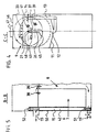
- the system is a schematic representation in a section along the plane C-C shown in Figure 2.
- This illustration helps to understand how the scoop tube 26 works.
- the scoop tube 26 sits eccentrically on the drive shaft 21.
- the inlet mouth 45 of the Scoop tube 26 describes the circle drawn.
- the one shown below Circle indicates the circumference of the drum 20.
- the pouring mouth 48 of the Scoop tube 26 is directed towards the rear in the direction of the drive axis 21. Below this Spout 48 of the scoop tube 26, the inlet channel 37 can be seen through the Opening 49 leads into the drum container 9.
- the drive shaft 21 can now turn on both sides.
- the scoop tube 26 dips with it Inlet mouth 45 into the oil separated and floated in the container space 8 and fat and skim a portion of it, this portion also containing water like.
- the level 39 in the container space 8 is indicated by the triangle 39.
- the scooped portion flows in the scoop tube 26 to its pouring mouth 48 and is finally poured onto the inlet channel 37, through which the fat, oil and water flows through the opening 49 into the drum container 9.
- the drive shaft 21 simultaneously drives the drum 20 and keeps it rotating. Because they driven by the two gears not shown here, it rotates in reverse Direction of rotation to the drive shaft 21.
- FIG. 5 shows a partial section along the plane B-B of FIG. 2. Is shown here the level 38 in the container space 7, which is slightly higher than the level 39 in adjoining container space 8, from which the fat and oil is skimmed off.
- the vertical Part of the drain pipe 15 is a precisely fitting pipe 50 with a bottom 51, that is permeable at the top and bottom by being perforated there as shown, for example.
- the tube 50 is equipped with a handle 52 at the top. His inside is filled with one special material 42, which has the ability to accumulate or absorb fat.
- the product MELT-BLOWN a textile composite, is suitable as a filling material made of polypropylene in granular form or as a tape, manufactured by the company ECOTEXTIL, 277 11 Hor ⁇ átky un Neratovic, Czech Republic.
- One gram of this The substance can accumulate about 12 to 18 grams of fat.
- the Tube 50 When flowing through the Tube 50 are thus the not yet separated or not separable fat and oil particles largely captured and retained by this material. If the Capacity of the material is exhausted, the tube 50 can be pulled out on the handle 52. The material is then emptied and replaced with new one. The oil and fat material is recycled by squeezing or centrifuging.
- solvents be used to extract the fat and oil substances. That through recycling accumulating fat and oil can be added to the container space 8 of the system.
- Figure 6 shows the system seen from above. All parts marked with numerals have been already described for the other figures.
- the drain pipe 15 designed as a square drain channel.
- the module consists of the actual grease separator functionally separated drum container 9 and the drum rotating in this container 20.
- This drum 20 is with carrier material for special fat and oil degrading Microorganisms filled. These aerobic microorganisms colonize this carrier material and when the drum 20 rotates, they are repeatedly immersed in the liquid in which drum 20 rotates, takes up oil and fat there and emerges again from this liquid open, then move through the air and are supplied with oxygen by it. They degrade the fats and oils.
- the result of the degradation Water has a low pH and is through the overflow line 13 in the Container space 8 of the fat separator, where it is with the large one located there
- the amount of water mixed so that its low pH has practically no effect on the Has pH in the container space 8 after mixing.
- By separating the drum container 9 of the remaining part of the system also becomes a buffer for temperature fluctuations educated. When a surge of hot water comes in from the dishwasher the system flows in, this has practically no influence on the temperature in the drum container 9.
- the amount of fat and oil supplied is not affected.
- the electrical control set or programmed so that, for example, the engine stops every hour and then it turns a few times in reverse. This draws on Scoop tube 26 a few servings in the drum container 9. How often this reversal of the Direction of rotation takes place and how many times the scoop tube 26 is to scoop is determined by Adapted case by case to the operating conditions of the respective kitchen and with the electrical Control programmed. The same is the case for the fan 36. This does not need to run constantly, but can, depending on the required activity of the microorganisms be switched on programmatically from time to time for a while. Further this also applies to the dosing pump for supplying additional nutrient solution for the Microorganisms in the drum 20.
- the specific microbiological aspects of this fat and oil degradation are disclosed below:
- lipases triazylglycerol of azylhydrolase, EC 3.1.1.3
- lipases in pure form are usually used for the hydrolysis of the triazylglycerols.
- the microorganisms that represent the major lipase producers include lipolytic yeasts, which are very often used biotechnologically. Your lipolytic enzymes are species-specific.
- Lipase synthesis in lipolytic yeasts is often positively influenced by the selected nitrogen source and the presence of citrate.
- Citric acid and in some cases also isocitric acid are the main metabolic products in the use of hydrocarbons, oils and fats as food sources for these microorganisms. The accumulation of these metabolic products in the cultivation medium causes their rapid acidification.
- the lipolytic yeast Yarrowia lipolytica is a particularly suitable microorganism for this plant for removing organic oils and fats, the Yarrowia lipolytica WI strain proving particularly suitable. The morphological and physiological properties of this yeast strain Yarrowia lipolytica WI are described and explained below.
- the yarrow strain Yarrowia lipolytica WI does not ferment maltose, sucrose, lactose, glucose, galactose and raffinose. It does not assimilate nitrates, but it assimilates L-lysine and erythritol. It grows at a temperature between 5 ° C and 35 ° C. It forms elliptical to oval cells in the liquid nutrient medium with oleic acid as the only carbon source. After 120 to 142 hours of cultivation, it forms pseudomycelium and real mycelium. There is no pigmentation. For growth in the synthetic medium, it does not require the presence of vitamins or any growth stimulators. This strain is sensitive to nystatin.
- von Arx is the amorphous form of Candida lipolytica (Harrison), Diddens et. Lodder. This microorganism was isolated from a soil contaminated with petroleum near an oil well in Hodonin, Czech Republic and deposited on April 16, 1996 at the Czech Microorganism Collection under the number CCM 4510 and under the same number a certificate of viability was issued. The address of this internationally recognized depository under the Budapest Treaty is: CCM - Czech Collection of Microorganisms, Masaryk University, Tvrdého 14, CR-602 00 Brno. A copy of the Receipt in the case of an Original Deposit and a copy of the Viability Statement are attached as Appendix 1 and Appendix 2 to the description.
- the high resistance of Yarrowia lipolytica WI to the effects of external factors, the low demands on the nutrient content in the environment, the strong viability and the high lipolytic activity make it possible to use this microorganism for biodegradation of fats and oils in closed containers and for continuous biodegradation of oils, greases and oil emulsions in the cleaning process of waste water contaminated in this way.
- the yeast strain is propagated and induced in the synthetic or organic medium in the presence of fatty acids or oils.
- the yeast is then used to colonize synthetic carriers for the microorganisms or these are used directly in the contaminated wastewater.
- the degradation of the oils and fats proceeds with the addition of air and with a sufficient concentration of nitrogen, whereby the ratio between the carbon contained in the oil or fat in this medium and the nitrogen must be maintained within the limits of the mass ratios 60 to 100: 1 .
- the optimal conditions for carrying out the process for the biodegradation of oils and fats using this yeast are at a pH of the medium of between 2.0 to 5.0 and at a temperature of 20 ° C. to 35 ° C.
- the organic or synthetic nutrient medium which forms a nitrogen and phosphorus source, mixed with other inorganic salts and trace elements as well as oleic acid or vegetable oil in a soluble form.
- the initial pH value of the cultivation medium can advantageously be adjusted to a value between 3.5 and 4.5 with citric acid, with intensive aeration with 0.3 to 1.0 liters of air per 1 liter of medium per hour at a temperature of 25 ° C up to 30 ° C the cultivation time is 24 to 72 hours.
- the end products of the biodegradation of oils and fats are carbon dioxide (CO 2 ), biomass and citric acid as the predominant metabolite.
- CO 2 carbon dioxide
- Other organic acids such as vinegar, apple, fumaric and oxoglutaric acids can also arise.
- these metabolites can also be converted into citric acid in the course of continuous fat biodegradation by the cells or used for biomass formation.
- the main advantage of this process for the biodegradation of fats and oils is that the resulting metabolites are primarily non-toxic and can easily be broken down by the usual microflora of biological wastewater treatment plants.
- Ribbons or fluffy cords made of synthetic fibers, preferably polyester, are suitable as the carrier material and can be populated with the cells induced by Yarrowia lipolytica WI .
- These ribbons or cords are wound in sections of approximately 1.50 m on approximately 10 cm long plastic tubes made of synthetic polymers, which have a diameter of, for example, 3 cm to 4 cm.
- the tubes are made of, for example, polyvinyl chloride, polyethylene or polypropylene.
- the drum 20 of the system which can be divided into several rooms, is filled with such wrapped pipe sections. Then this carrier material is populated with the cells induced by Yarrowia lipolytica WI , after which the system is ready for operation and the fat and oil can be added continuously or at intervals.
- the medium in the drum container 9 contained NH 4 + as a nitrogen source in a concentration of 100 mg / l to 400 mg / l.
- the pH in the medium was between 1.02 and 3.0 within 35 weeks.
- the temperature of the medium ranged between 25 ° C and 28 ° C.
- the water on leaving the system contained oil in a concentration of 38.25 mg / l to 48.12 mg / l (gravimetric determination after extraction into the organic solvent).
- Representatives of the species Yarrowia lipolytica in particular the strain Yarrowia lipolytica WI, have good lipolytic activity in the presence of oils and fats, similar to the presence of the emulsions of these substances in the water medium.
- the biodegradation rate of these contaminants of the water medium by the cells of the Yarrowia lipolytica Wl strain is within wide limits of the pH value between 0.8 and 7.0 and relatively high at temperatures of 5 ° C to 35 ° C.
- Conditions for achieving the optimal physiological activity of Yarrowia lipolytica WI are: Firstly, an adequate oxygen supply in limits between 0.3 and 1.0 liters of air per 1 liter of waste water and hour, secondly, a sufficient NH 4 + concentration of at least 60mg / l and third, a concentration of 0.1% to 3% (w / v) fat or oil in the medium.
- the wastewater discharged from the plant is only weakly acidified by the citric acid. It can be easily cleaned in the municipal sewage treatment plants.
Description
- Figur 1:
- Eine Anlage zum Beseitigen von Fetten und Oelen in einer perspektivischen Ansicht, teilweise aufgeschnitten;
- Figur 2
- Eine Anlage zum Abscheiden und nachfolgenden Beseitigen von Fetten und Oelen in Abwässern in einer perspektivischen Ansicht, teilweise aufgeschnitten;
- Figur 3:
- Die Anlage gemäss Figur 2 von der Seite her gesehen schematisch, in einem Schnitt längs der Ebene A-A in Figur 2;
- Figur 4:
- Die Anlage gemäss Figur 2 von links her gesehen schematisch, in einem Schnitt längs der Ebene C-C in Figur 2;
- Figur 5:
- Die Anlage gemäss Figur 2 von der Seite her gesehen schematisch, in einem Schnitt längs der Ebene B-B in Figur 2.
Claims (10)
- Anlage zum Beseitigen von Fett und Oel, mit einem Behälterraum (9) zur Aufnahme eines flüssigen Mediums, aus welchem Behälterraum (9) über einen unten liegenden Ablauf (12) ein aufsteigendes Ueberlaufrohr (55) führt, das ausserhalb des Behälterraumes (9) mündet, sodass dessen innere Unterkante beim Auslauf das Niveau des Mediums im Behälterraum (9) definiert, wobei im Behälterraum (9) mit fett- und öl-degradierenden Mikroorganismen besiedeltes Trägermaterial vorhanden ist, weiter dass die Anlage Mittel zur Versorgung dieser Mikroorganismen mit Luft sowie eine Zudosiereinrichtung (56-60;26,37) mit speicherprogrammierbarer Steuerung einschliesst, mittels welcher zuvor abgeschiedenes Fett und Oel aus einem zur Anlage gehörigen Behälterraum (7) oder aus einem gesonderten Fettabscheider dem Behälterraum (9) dosiert zuführbar ist.
- Anlage nach Anspruch 1 zum Abscheiden und nachfolgenden Beseitigen von Fetten und Oelen in Abwässern, bestehend aus einem Behälter (1) mit einem Zulauf- (2) und einem Ablaufrohr (15), dadurch gekennzeichnet, dass dessen Inneres wenigstens einen Behälterraum (7,8) zum Abscheiden der Fette und Oele aus dem zulaufenden Abwasser aufweist, und weiter einen davon getrennten Behälterraum (9), in dem mit fettund öl-degradierenden Mikroorganismen besiedeltes Trägermaterial vorhanden ist.
- Anlage nach Anspruch 2, dadurch gekennzeichnet, dass im Behälterraum (9) eine Trommel (20) drehbar gelagert ist, in welcher das besiedelte Trägermaterial untergebracht ist, wobei die Trommel (20) elektrisch antreibbar ist, und dass die Zudosiereinrichtung (26,37) durch ein um eine Achse (21) drehbares Schöpfrohr (26) mit Einleitkanal (37) gebildet ist.
- Anlage nach einem der vorhergehenden Ansprüche, dadurch gekennzeichnet, dass sie einen Ventilator (36) mit Rückschlagklappe aufweist, mit dem Luft in das Innere des des Behälterraumes (9) einblasbar ist, oder dass eine Sauerstoff- oder Luftzuführeinrichtung vorhanden ist, mittels derer Luft oder Sauerstoff in feinen Mikrobläschen unten in den Behälterraum (9) einpumpbar ist, und dass der Behälter (1) zur Entlüftung einen Geruchfilter (47) oder eine Oeffnung im durch den Behälter (1) verlaufenden Ablaufrohr (55;15) aufweist, und dass sie einen Behälter mit Dosierpumpe zur bedarfsweisen Zufuhr von Nährlösung in den Behälterraum (9) für die fett- und öldegradierenden Mikroorganismen aufweist, sowie dass sie eine speicherprogrammierbare elektrische Steuerung aufweist, mittels der die Zudosierung von Fett und Oel, die Zufuhr von Luft oder Sauerstoff und die Zudosierung von NH4 + in den Behälterraum (9) regelbar ist.
- Anlage nach einem der vorhergehenden Ansprüche, dadurch gekennzeichnet, dass das Trägermaterial im Behälterraum (9) aus einer Vielzahl von mit Polyesterschnüren bewickelten Kunststoff-Röhrchen besteht, die mit der Hefe Yarrowia lipolytica W1 der Hinterlegung CCM 4510 besiedelt sind, und dass ein Behälter mit Dosierpumpe zur bedarfsweisen Zufuhr von NH4 + als Stickstoffquelle in den Behälterraum (9) für die Fett- und Oel-degradierenden Mikroorganismen vorhanden ist.
- Anlage nach einem der Ansprüche 2 bis 5, dadurch gekennzeichnet, dass der Behälter (1) im Anschluss an das Einlaufrohr (2) zunächst einen Behälterraum (7) zur Abscheidung und als Sinkstoffraum für Schlämme und Feststoffe aufweist, daran anschliessend durch eine Trennwand (3) abgetrennt einen Behälterraum (8) mit niedrigerem Pegel (39) zur weiteren Abscheidung, aus welchem mit der Zudosiereinrichtung (25,37) abgeschiedenes Oel und Fett entnehmbar ist, dann den durch eine Trennwand (10) und einen Kännelboden (11) vom Behälterraum (8) abgetrennten Behälterraum (9), in dem mit fett- und öldegradierenden Mikroorganismen besiedeltes Trägermaterial vorhanden ist, und aus dessen Boden (11) ein Ueberlaufrohr (13) im Behälterraum (8) oberhalb des Pegels (39) im Behälterraum (8) mündet.
- Anlage nach einem der Ansprüche 2 bis 6, dadurch gekennzeichnet, dass unterhalb des Behälterraumes (8) und von diesem mit einem geneigten und durchlässigen Boden (16) abgetrennt in einem Behälterraum (18) eine Reihe von eng nebeneinander und schräg angeordneten Lamellen (44) mit ölanziehender Oberfläche angeordnet sind, durch welche das mittels Abscheidung gereinigte Abwasser zwangsweise strömen muss, bevor es in das Ablaufrohr (15) gelangt, und dass das Ablaufrohr (15) durch einen Behälter (50) führt, dessen Inneres mit einem Material (42) gefüllt ist, das die Fähigkeit hat, Fett zu akkumulieren beziehungsweise aufzusaugen, wonach das Ablaufrohr (15) aus dem Behälter (1) herausführt.
- Anlage nach Anspruch 7, dadurch gekennzeichnet, dass der Behälter (50) ein mit einem Boden (51) verschlossenes Rohr (50) ist, das an beiden Enden durchlässig ist und durch eine Oeffnung passgenau in den aufsteigenden Teil des Ablaufrohres (15) gestellt ist und mit Material (42) gefüllt ist, das die Fähigkeit hat, Fett zu akkumulieren beziehungsweise aufzusaugen.
- Anlage nach einem der Ansprüche 1, 4 oder 5, dadurch gekennzeichnet, dass die Zudosiereinrichtung aus einem Rohr (58) mit Archimedes-Schraube (59) besteht, die von einem Motor (60) antreibbar ist, und dass von diesem Rohr (58) ein Rohr (57,56) in den Behälterrraum (9) abzweigt und dort mündet, sowie dass aus dem Behälterraum (9) ein Ueberlaufrohr (55) hinausführt, dessen Steighöhe den Pegelstand im Behälterraum (9) definiert.
- Anlage nach einem der vorhergehenden Ansprüche, dadurch gekennzeichnet, dass sie oben mit einem Deckel (46), der auf einer Gummidichtung ruht, geruchsdicht verschlossen ist, wobei der Deckel (46) scharnierend aufschwenkbar und mittels Gasfedern gestützt ist.
Applications Claiming Priority (3)
| Application Number | Priority Date | Filing Date | Title |
|---|---|---|---|
| DE19547400 | 1995-12-19 | ||
| DE19547400 | 1995-12-19 | ||
| PCT/CH1996/000451 WO1997022560A1 (de) | 1995-12-19 | 1996-12-19 | Anlage zum beseitigen von fetten und ölen |
Publications (2)
| Publication Number | Publication Date |
|---|---|
| EP0876302A1 EP0876302A1 (de) | 1998-11-11 |
| EP0876302B1 true EP0876302B1 (de) | 2000-07-26 |
Family
ID=7780544
Family Applications (1)
| Application Number | Title | Priority Date | Filing Date |
|---|---|---|---|
| EP19960942222 Expired - Lifetime EP0876302B1 (de) | 1995-12-19 | 1996-12-19 | Anlage zum beseitigen von fetten und ölen |
Country Status (7)
| Country | Link |
|---|---|
| US (1) | US6059963A (de) |
| EP (1) | EP0876302B1 (de) |
| AT (1) | ATE194971T1 (de) |
| AU (1) | AU1136597A (de) |
| DE (1) | DE59605660D1 (de) |
| ES (1) | ES2150703T3 (de) |
| WO (1) | WO1997022560A1 (de) |
Families Citing this family (20)
| Publication number | Priority date | Publication date | Assignee | Title |
|---|---|---|---|---|
| US6245236B1 (en) * | 1999-05-26 | 2001-06-12 | Cercona Of America Inc. | Reciprocating biological filter |
| NL1015778C2 (nl) * | 2000-07-21 | 2002-01-24 | Kessel K A Techniek B V | Inrichting voor het afscheiden van koolwaterstoffen uit water. |
| US6491830B1 (en) * | 2001-05-16 | 2002-12-10 | Thermaco, Inc. | Kitchen grease removal system |
| US6800195B1 (en) | 2002-06-04 | 2004-10-05 | Thermaco, Inc. | Low cost grease removal system |
| SE525213C2 (sv) * | 2003-05-23 | 2004-12-28 | Hyosong M Lee | Förfarande och anordning för kontinuerlig filtrering av partiklar ur en vätska |
| US6849176B1 (en) | 2003-09-04 | 2005-02-01 | Thermaco, Inc. | Grease separator for kitchen sinks and other applications |
| US7001515B2 (en) * | 2003-10-14 | 2006-02-21 | Townsend Engineering Company | Dual filter system for filtering of injector fluids |
| US7134152B1 (en) | 2003-12-17 | 2006-11-14 | Clearline Systems, Inc. | Adaptable, low cost air gap and flow control |
| US7208080B2 (en) | 2004-09-16 | 2007-04-24 | Thermaco, Inc. | Low cost oil/grease separator |
| US7504024B1 (en) | 2005-04-19 | 2009-03-17 | Thermaco, Inc. | Apparatus for draining at least one sink |
| FR2887466B1 (fr) * | 2005-06-27 | 2007-10-05 | Fr Environnement Nautique Soc | Cuve de traitement d'effluents provenant d'aires techniques |
| JP4490904B2 (ja) * | 2005-11-22 | 2010-06-30 | シャープ株式会社 | 水処理装置 |
| US9771711B1 (en) | 2014-12-05 | 2017-09-26 | Thermaco, Inc. | Indoor grease trap with multiple plumber fitting possibilities |
| JP6674817B2 (ja) * | 2016-03-31 | 2020-04-01 | シーシーアイホールディングス株式会社 | 排水の処理方法、および排水処理用キット |
| CN106219672B (zh) * | 2016-09-29 | 2023-03-14 | 成都安信德环保设备有限公司 | 一种除油方法及除油装置 |
| JP6920089B2 (ja) * | 2017-03-31 | 2021-08-18 | シーシーアイホールディングス株式会社 | 生菌製剤の製造方法、ならびに生菌製剤およびこれを用いた排水処理方法 |
| EP3713879A4 (de) | 2017-11-21 | 2021-08-25 | Thermaco, Inc. | Feststofftransferpumpe mit modularen komponenten |
| TWI742810B (zh) * | 2020-08-19 | 2021-10-11 | 湯鈺婷 | 油氣淨化裝置 |
| US20220355225A1 (en) * | 2021-05-10 | 2022-11-10 | Lyco Manufacturing Inc. | Externally Fed Screen for Filtration |
| CO2022006070A1 (es) * | 2022-05-10 | 2022-05-20 | Zhanasolutions Green Eng Sas | Dispositivo compacto para el tratamiento primario de aguas residuales industriales provenientes de cocinas industriales |
Family Cites Families (12)
| Publication number | Priority date | Publication date | Assignee | Title |
|---|---|---|---|---|
| US3428555A (en) * | 1966-01-10 | 1969-02-18 | Hitachi Chemical Co Ltd | Method and an apparatus for purifying waste |
| US4755296A (en) * | 1985-03-21 | 1988-07-05 | Occidental Chemical Corporation | Integrated biological-adsorption process for treating waste water |
| JPH03278897A (ja) * | 1990-03-07 | 1991-12-10 | T D Ii:Kk | 有機性廃水の処理方法 |
| US5126050A (en) * | 1990-05-10 | 1992-06-30 | Sbr Technologies, Inc. | Granular activated carbon-sequencing batch biofilm reactor (GAC-SBBR) |
| US5240600A (en) * | 1990-07-03 | 1993-08-31 | International Environmental Systems, Inc., Usa | Water and wastewater treatment system |
| US5354458A (en) * | 1990-07-11 | 1994-10-11 | International Environmental Systems, Inc., Usa | Sequencing batch liquid treatment |
| JPH06102196B2 (ja) * | 1991-01-30 | 1994-12-14 | 岩雄 植田 | 雑排水の処理装置 |
| FR2684664B1 (fr) * | 1991-12-10 | 1994-09-30 | Saint Dizier Ste Cale | Procede et dispositif de multiplication de souches selectionnees, appliques au traitement des graisses et des fecules. |
| JP3385074B2 (ja) * | 1993-09-08 | 2003-03-10 | 株式会社フジタ | 油脂を含有する廃水の微生物処理法 |
| JP2816087B2 (ja) * | 1993-10-01 | 1998-10-27 | 株式会社西原環境衛生研究所 | 脂質含有廃水の生物学的処理装置 |
| JPH08182995A (ja) * | 1994-12-28 | 1996-07-16 | Corona Giken Kogyo Kk | 活性化バクテリヤ供給装置 |
| CZ137895A3 (en) * | 1995-05-29 | 1996-12-11 | Horakova Dana Csc | The use of yarrowia lipolytica for biological degradation of oils and fats in the waste water or sewage treatment process and the way of use thereof |
-
1996
- 1996-12-19 ES ES96942222T patent/ES2150703T3/es not_active Expired - Lifetime
- 1996-12-19 US US09/077,981 patent/US6059963A/en not_active Expired - Fee Related
- 1996-12-19 AU AU11365/97A patent/AU1136597A/en not_active Abandoned
- 1996-12-19 WO PCT/CH1996/000451 patent/WO1997022560A1/de active IP Right Grant
- 1996-12-19 AT AT96942222T patent/ATE194971T1/de not_active IP Right Cessation
- 1996-12-19 DE DE59605660T patent/DE59605660D1/de not_active Expired - Fee Related
- 1996-12-19 EP EP19960942222 patent/EP0876302B1/de not_active Expired - Lifetime
Also Published As
| Publication number | Publication date |
|---|---|
| DE59605660D1 (de) | 2000-08-31 |
| EP0876302A1 (de) | 1998-11-11 |
| US6059963A (en) | 2000-05-09 |
| ATE194971T1 (de) | 2000-08-15 |
| ES2150703T3 (es) | 2000-12-01 |
| WO1997022560A1 (de) | 1997-06-26 |
| AU1136597A (en) | 1997-07-14 |
Similar Documents
| Publication | Publication Date | Title |
|---|---|---|
| EP0876302B1 (de) | Anlage zum beseitigen von fetten und ölen | |
| AT410665B (de) | Verfahren zur filterung von abwasser und behandlung von organischem abfall sowie vorrichtung zur durchführung des verfahrens | |
| DE3929510C2 (de) | ||
| DE2713088A1 (de) | Anlage fuer die abwasserklaerung durch flotation aufgrund von entspannung geloester luft | |
| DE4114160C2 (de) | Vorrichtung zur mechanischen und biologischen Zerlegung von organischen Haushaltsabfällen | |
| DE2032890A1 (de) | Verfahren und Vorrichtung zur Be handlung von Abwasser | |
| DE2726167A1 (de) | Verfahren zur behandlung von abwasser | |
| DE1484823A1 (de) | Biochemisches Verfahren und Anlage zur Abwasserreinigung | |
| DE3123181C2 (de) | Vorrichtung zum Rühren und Belüften von Gülle | |
| DE69928153T2 (de) | Automatischer Biogenerator | |
| DE2544177A1 (de) | Vorrichtung zur umsetzung von in waessern, insbesondere abwaessern, enthaltenen fremdstoffen, insbesondere schadstoffen, in unschaedliche stoffe | |
| WO1992012785A1 (en) | Effluent treatment | |
| CH626864A5 (en) | Process and arrangement for treating liquids, in particular waste water. | |
| Lohmeyer | Trickling filters and operation tips | |
| Trebler et al. | Dairy Waste Elimination and Sewage Disposal [with Discussion] | |
| DE1913703A1 (de) | Fischaufzucht-Ring-Fliesskanal | |
| DE3826968A1 (de) | Abscheider fuer insbesondere in abwaessern befindliche oele und fette | |
| EP2100856A1 (de) | Verfahren zur mikrobiologischen Behandlung von Wasser aus fliessenden und/oder stehenden Gewässern | |
| DE2020158C3 (de) | Verfahren zur biologischen Behandlung von fette und nicht fette Abfälle enthaltenden Abwässern | |
| AT394544B (de) | Vorrichtung zur entsorgung, insbesondere hygienisierung, des in einer klaeranlage anfallenden schlammes | |
| DE2445636C3 (de) | ||
| CH634803A5 (en) | Plant for the anaerobic purification of waste water | |
| DE2904449A1 (de) | Anlage zum anaeroben reinigen von abwasser | |
| EP1669326A1 (de) | Verfahren und Vorrichtung zum Reinigen von organische Substanzen enthaltenden Abwässern | |
| DE1592665A1 (de) | Vorrichtung zum Kompostieren von Abfallstoffen |
Legal Events
| Date | Code | Title | Description |
|---|---|---|---|
| PUAI | Public reference made under article 153(3) epc to a published international application that has entered the european phase |
Free format text: ORIGINAL CODE: 0009012 |
|
| 17P | Request for examination filed |
Effective date: 19980710 |
|
| AK | Designated contracting states |
Kind code of ref document: A1 Designated state(s): AT BE CH DE DK ES FR GB IT LI NL SE |
|
| GRAG | Despatch of communication of intention to grant |
Free format text: ORIGINAL CODE: EPIDOS AGRA |
|
| 17Q | First examination report despatched |
Effective date: 19990121 |
|
| GRAG | Despatch of communication of intention to grant |
Free format text: ORIGINAL CODE: EPIDOS AGRA |
|
| GRAH | Despatch of communication of intention to grant a patent |
Free format text: ORIGINAL CODE: EPIDOS IGRA |
|
| GRAH | Despatch of communication of intention to grant a patent |
Free format text: ORIGINAL CODE: EPIDOS IGRA |
|
| GRAA | (expected) grant |
Free format text: ORIGINAL CODE: 0009210 |
|
| AK | Designated contracting states |
Kind code of ref document: B1 Designated state(s): AT BE CH DE DK ES FR GB IT LI NL SE |
|
| PG25 | Lapsed in a contracting state [announced via postgrant information from national office to epo] |
Ref country code: NL Free format text: LAPSE BECAUSE OF FAILURE TO SUBMIT A TRANSLATION OF THE DESCRIPTION OR TO PAY THE FEE WITHIN THE PRESCRIBED TIME-LIMIT Effective date: 20000726 |
|
| REF | Corresponds to: |
Ref document number: 194971 Country of ref document: AT Date of ref document: 20000815 Kind code of ref document: T |
|
| REG | Reference to a national code |
Ref country code: CH Ref legal event code: EP |
|
| REF | Corresponds to: |
Ref document number: 59605660 Country of ref document: DE Date of ref document: 20000831 |
|
| REG | Reference to a national code |
Ref country code: CH Ref legal event code: NV Representative=s name: FELBER & PARTNER AG PATENTANWAELTE |
|
| ITF | It: translation for a ep patent filed |
Owner name: ORGANIZZAZIONE D'AGOSTINI |
|
| PG25 | Lapsed in a contracting state [announced via postgrant information from national office to epo] |
Ref country code: SE Free format text: LAPSE BECAUSE OF FAILURE TO SUBMIT A TRANSLATION OF THE DESCRIPTION OR TO PAY THE FEE WITHIN THE PRESCRIBED TIME-LIMIT Effective date: 20001026 Ref country code: DK Free format text: LAPSE BECAUSE OF FAILURE TO SUBMIT A TRANSLATION OF THE DESCRIPTION OR TO PAY THE FEE WITHIN THE PRESCRIBED TIME-LIMIT Effective date: 20001026 |
|
| ET | Fr: translation filed | ||
| GBT | Gb: translation of ep patent filed (gb section 77(6)(a)/1977) |
Effective date: 20001020 |
|
| REG | Reference to a national code |
Ref country code: ES Ref legal event code: FG2A Ref document number: 2150703 Country of ref document: ES Kind code of ref document: T3 |
|
| PG25 | Lapsed in a contracting state [announced via postgrant information from national office to epo] |
Ref country code: BE Free format text: LAPSE BECAUSE OF NON-PAYMENT OF DUE FEES Effective date: 20001231 |
|
| NLV1 | Nl: lapsed or annulled due to failure to fulfill the requirements of art. 29p and 29m of the patents act | ||
| PLBE | No opposition filed within time limit |
Free format text: ORIGINAL CODE: 0009261 |
|
| STAA | Information on the status of an ep patent application or granted ep patent |
Free format text: STATUS: NO OPPOSITION FILED WITHIN TIME LIMIT |
|
| BERE | Be: lapsed |
Owner name: BIOREM A.G. Effective date: 20001231 |
|
| 26N | No opposition filed | ||
| PGFP | Annual fee paid to national office [announced via postgrant information from national office to epo] |
Ref country code: ES Payment date: 20011227 Year of fee payment: 6 |
|
| PGFP | Annual fee paid to national office [announced via postgrant information from national office to epo] |
Ref country code: FR Payment date: 20011228 Year of fee payment: 6 |
|
| REG | Reference to a national code |
Ref country code: GB Ref legal event code: IF02 |
|
| PG25 | Lapsed in a contracting state [announced via postgrant information from national office to epo] |
Ref country code: ES Free format text: LAPSE BECAUSE OF NON-PAYMENT OF DUE FEES Effective date: 20021220 |
|
| PGFP | Annual fee paid to national office [announced via postgrant information from national office to epo] |
Ref country code: GB Payment date: 20030617 Year of fee payment: 7 Ref country code: DE Payment date: 20030617 Year of fee payment: 7 Ref country code: CH Payment date: 20030617 Year of fee payment: 7 Ref country code: AT Payment date: 20030617 Year of fee payment: 7 |
|
| PG25 | Lapsed in a contracting state [announced via postgrant information from national office to epo] |
Ref country code: FR Free format text: LAPSE BECAUSE OF NON-PAYMENT OF DUE FEES Effective date: 20030901 |
|
| REG | Reference to a national code |
Ref country code: FR Ref legal event code: ST |
|
| PG25 | Lapsed in a contracting state [announced via postgrant information from national office to epo] |
Ref country code: GB Free format text: LAPSE BECAUSE OF NON-PAYMENT OF DUE FEES Effective date: 20031219 Ref country code: AT Free format text: LAPSE BECAUSE OF NON-PAYMENT OF DUE FEES Effective date: 20031219 |
|
| PG25 | Lapsed in a contracting state [announced via postgrant information from national office to epo] |
Ref country code: LI Free format text: LAPSE BECAUSE OF NON-PAYMENT OF DUE FEES Effective date: 20031231 Ref country code: CH Free format text: LAPSE BECAUSE OF NON-PAYMENT OF DUE FEES Effective date: 20031231 |
|
| PG25 | Lapsed in a contracting state [announced via postgrant information from national office to epo] |
Ref country code: DE Free format text: LAPSE BECAUSE OF NON-PAYMENT OF DUE FEES Effective date: 20040701 |
|
| REG | Reference to a national code |
Ref country code: FR Ref legal event code: RN |
|
| GBPC | Gb: european patent ceased through non-payment of renewal fee |
Effective date: 20031219 |
|
| REG | Reference to a national code |
Ref country code: CH Ref legal event code: PL |
|
| REG | Reference to a national code |
Ref country code: ES Ref legal event code: FD2A Effective date: 20021220 |
|
| REG | Reference to a national code |
Ref country code: FR Ref legal event code: D5 |
|
| PG25 | Lapsed in a contracting state [announced via postgrant information from national office to epo] |
Ref country code: IT Free format text: LAPSE BECAUSE OF NON-PAYMENT OF DUE FEES;WARNING: LAPSES OF ITALIAN PATENTS WITH EFFECTIVE DATE BEFORE 2007 MAY HAVE OCCURRED AT ANY TIME BEFORE 2007. THE CORRECT EFFECTIVE DATE MAY BE DIFFERENT FROM THE ONE RECORDED. Effective date: 20051219 |