EP0877226A2 - Monolithic vibrating beam angular velocity sensor - Google Patents
Monolithic vibrating beam angular velocity sensor Download PDFInfo
- Publication number
- EP0877226A2 EP0877226A2 EP97310093A EP97310093A EP0877226A2 EP 0877226 A2 EP0877226 A2 EP 0877226A2 EP 97310093 A EP97310093 A EP 97310093A EP 97310093 A EP97310093 A EP 97310093A EP 0877226 A2 EP0877226 A2 EP 0877226A2
- Authority
- EP
- European Patent Office
- Prior art keywords
- beams
- angular velocity
- velocity sensor
- sensor
- suspending
- Prior art date
- Legal status (The legal status is an assumption and is not a legal conclusion. Google has not performed a legal analysis and makes no representation as to the accuracy of the status listed.)
- Granted
Links
Images


Classifications
-
- G—PHYSICS
- G01—MEASURING; TESTING
- G01C—MEASURING DISTANCES, LEVELS OR BEARINGS; SURVEYING; NAVIGATION; GYROSCOPIC INSTRUMENTS; PHOTOGRAMMETRY OR VIDEOGRAMMETRY
- G01C19/00—Gyroscopes; Turn-sensitive devices using vibrating masses; Turn-sensitive devices without moving masses; Measuring angular rate using gyroscopic effects
- G01C19/56—Turn-sensitive devices using vibrating masses, e.g. vibratory angular rate sensors based on Coriolis forces
- G01C19/5642—Turn-sensitive devices using vibrating masses, e.g. vibratory angular rate sensors based on Coriolis forces using vibrating bars or beams
- G01C19/5656—Turn-sensitive devices using vibrating masses, e.g. vibratory angular rate sensors based on Coriolis forces using vibrating bars or beams the devices involving a micromechanical structure
Definitions
- the present invention relates to angular velocity sensors. More particularly, this invention pertains to a batch processed silicon beam array angular velocity sensor based upon the Coriolis sensing method.
- Gyroscopes include, for example, complex and difficult-to-manufacture gimballed spinning rotors, strapdown sensors such the ring laser and fiber optic gyroscopes. All of the above-named rate sensing devices are characterized by high cost, large size and power consumption, complexity of manufacture, expense of maintenance.
- the reference motion of the tines of the tuning fork changes the moment of inertia cyclically.
- the rotation rate must change cyclically in a complementary fashion to conserve the angular momentum.
- the physical operation of the tuning fork type sensor is similar to that of a spinning ice skater who spins faster by pulling his arms in and slows down by extending them. Consequently, in a tuning fork sensor the outward-and inward radial vibration of the tines is converted into a rotational vibration whose amplitude is proportional to the input rate.
- a closed loop vibrating rotation rate sensor is disclosed in United States patent 5,056,366 of Samuel N. Fersht et al. entitled "Piezoelectric Vibratory Rate Sensor.”
- a type of angular velocity sensing device of lesser complexity whose operation also is based upon the measurement of Coriolis forces is disclosed in United States patent 3,520,195 of Stephen W. Tehon titled “Solid State Angular Velocity Sensing Device” and discussed by William D. Gates in an article titled “Vibrating Angular Rate Sensor May Threaten the Gyroscope", Electronics , pp. 130-134 (June 10, 1968).
- This device comprises a square metallic rod that is suspended at its nodal supports from a metal frame. The rod is driven at its fundamental frequency by a piezoelectric drive electrode fixed to one surface while a piezoelectric transducer that serves as a output signal pickoff is fixed to an orthogonal surface.
- the piezoelectric elements that serve, inter alia , as drive and pickoff electrodes are bonded to the metallic surfaces of the vibrating rod by organic adhesive.
- Such adhesive materials absorb energy, causing a reduction in the Q of the vibrating rod. As a consequence, more energy must be input into the rod for the purpose of overcoming damping forces that work against vibration driving forces.
- VYRO A variation of the VYRO is disclosed in an article by Brian Dance, "Piezoelectric Ceramic Elements for Compact Gyroscope", Design News , pgs. 113, 114 (9/20/93).
- the device described comprises an angular velocity sensor of Murata Ltd. of the United Kingdom whose sensing element is formed of "ELINVAR", a nickel-chromium steel alloy.
- the bar may be of either circular or equilateral triangle cross section.
- a number of piezoelectric elements are fixed to the sensing element. Again, this device is not suitable for batch processing and is subject to performance degradation due to the presence of organic material for bonding the piezoelectric transducer elements to the vibrating sensor.
- an angular velocity sensor Such sensor includes an elongated beam.
- a frame has an internal aperture for accommodating the beam.
- Means are provided for suspending the beam within the aperture.
- Means, fixed to the beam, is provided for flexibly driving the beam as well as for detecting the presence and amplitude of magnitude of Coriolis force exerted thereupon.
- the beam, the means for suspending and the frame are an integral structure comprising silicon.
- the present invention comprises a monolithic angular velocity sensor.
- a monolithic angular velocity sensor including a plurality of sensor elements formed within a substantially planar silicon substrate.
- Each sensor element includes an elongated beam.
- the major axes of the elongated beam of the sensor elements are aligned parallel to one another.
- the present invention provides a monolithic angular velocity sensor for sensing rotation rates about two orthogonal axes.
- the sensor includes a first sensor element and a second sensor element formed within a silicon substrate.
- Each of such sensor elements includes an elongated beam.
- the major axes of the elongated beams of said sensor elements are aligned orthogonal to one another.
- the present invention provides a monolithic angular velocity sensor array for sensing rotation about two orthogonal axes.
- a first array of sensor elements includes a first plurality of elongated bears aligned parallel to one another.
- a second array comprises a second plurality of elongated beams aligned parallel to one another. The axes of the beams of the first array are aligned orthogonal to those of the second array.
- Each array is integral with a silicon substrate.
- the invention comprises a silicon-based device of the microelectro-mechanical system (MEMS) type. As such, it is inherently suitable for integration with on-chip electronics.
- MEMS microelectro-mechanical system
- devices in accordance with the invention may be formed by means of known bulk and surface micromachining process technology.
- an angular velocity sensor 10 in accordance with the invention comprises a monolithic structure micromachined from a wafer of silicon. Such wafers are conventionally prepared with disk-like surfaces of about six to eight inches or more in diameter. By employing known micromachining techniques, more than 100 angular velocity sensors in accordance with the invention can be formed from a single such wafer. This contrasts significantly with the sizes and yields of angular velocity sensors and manufacturing processes therefor in accordance with the prior art that do not take advantage of the manufacturing efficiencies offered by silicon fabrication technology.
- the sensor 10 comprises an elongated beam 12 that is suspended within an internal aperture 14 of a frame 16.
- Transverse members, aligned in pairs, 18, 18', 20, 20' fixed to the sides of the aperture 14 and the bar 12 support the beam 12 therein.
- Elongated electrodes are fixed to the upper and lower surfaces of the beam 12. Identical arrangements of electrodes are fixed to the top and bottom surfaces of the elongated beam 12, each comprising a central electrode 22, 22' and, spaced therefrom, symmetrically arranged edge electrodes 24, 24' and 26, 26'.
- the central electrodes 22, 22' are provided for receiving electrical signals which act, in conjunction with underlying piezoelectric elements (discussed below), to drive or vibrate the elongated beam 12 at its natural frequency while the edge electrodes 24, 24' and 26, 26' serve as pickoffs for receiving electrical charge generated within underlying piezoelectric elements that results from Coriolis-force induced bending or vibration in the transverse plane.
- Such Coriolis force is occasioned by, and proportional to the existence of an angular rate ⁇ about the sensitive or input axis 28 of the sensor 10.
- the input axis of the angular velocity sensor 10 is aligned with the major or longitudal axis of the beam 12.
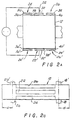
- Figures 2(a) and 2(b) are a cross-sectional view taken at line 2(a)-2(a) and a top planar view of the beam 12 of Figure 1, respectively.
- the electrodes comprise patterned arrangements of metallizations 30, 30', 32, 32' and 34, 34' deposited atop a patterned thin film layer of active pzt electroceramic material comprising underlying segments 36, 36', 38, 38' and 40, 40'.
- the segments of electroceramic material may be deposited upon the silicon beam 12 by a number of processes including, but not limited to, sol-gel deposition and planar magnetron sputtering.
- the electrodes 24 through 26' are fabricated at the top and bottom surfaces of the elongated beam 12. As such, their location facilitates the use of batch processing methods for forming large pluralities of angular velocity sensors.
- Silicon semiconductor processing techniques are essentially "vertical" in nature. That is, various silicon manufacturing processes including, for example, ion etching and photolithography, rely in large measure upon the patterning of horizontal planar surfaces for subsequent processing steps.
- bulk micromachining processing e.g. inductively-coupled plasma reactive ion etching
- silicon-based devices further allows the formation of devices such as the present invention which feature structures having vertically squared-off shapes.
- a top planar view of the elongated beam 12 one may observe that the transverse members or ears 18, 18', 20 and 20' that suspend the elongated bar 12 flexibly within the frame 16 are aligned in pairs 18, 18' and 20, 20' a distance "d" from the opposed ends of the beam 12.
- the distance d is such that the transverse pairs of ears suspend the elongated beam 12 at its nodal points. That is, for a beam 12 of known geometry and material composition, the pairs of aligned ears support the beam 12 at the null or nodal points of beam vibration. By so locating the points of support, maximum Q value is obtained.
- a monolithic device of silicon a high-Q material
- the beam 12 is supported by means of transverse silicon ears 18 through 20' formed integral therewith rather than by means of an organic adhesive, vibrational losses and consequent degradation of Q value is avoided.
- Figures 3(a) and 3(b) are side elevation and top planar views, respectively, of the sensor of Figure 1 for illustrating the vibratory response of the elongated beam 12 to an applied driving signal and the Coriolis force-induced beam vibration experienced by a sensor in accordance with the invention.
- the beam 12 is driven to vibrate at its natural frequency by signals applied to the electrodes 22 and 22' that affect simultaneous contractions and expansions of the segments of electroceramic pzt material 38 and 38' which alternate or oscillate over time.
- the application of the identical waveform to the overlying electrodemetallizations at the top and bottom of the beam 12 will produce the desired tandem of alternating compressions and expansions of the contacting pzt segments to produce bending of the beam 12 within a vertical plane.
- the transverse ears 18 and 20, located at the nodal points of the beam 12 are only minimally stressed by such bending.
- FIG. 3(b) a top planar view of the sensor 10, one can see that the angular velocity-induced deflection of the beam 12 due to Coriolis forces occurs in the horizontal plane, transverse to the plane in which the beam 12 is driven.
- the metallizations 30 and 34 that overlie such electroceramic sections are electrically connected through measuring circuitry (not shown) for measuring the changes in the internal dipole moments of electroceramic segments 36 and 40.
- a similar arrangement measures the stress-induced bending of the electroceramic segments of the pickoff electrodes 24' and 26' located at the bottom of beam 12. Redundant measurement of the angular velocity-induced Coriolis force exerted upon the elongated beam is thereby obtained.
- Figure 4 is a top planar view of a monolithic angular velocity sensor for sensing angular rotation about orthogonal axes 42 and 44.
- the two-axis angular velocity sensor is formed on a silicon substrate 46.
- Orthogonally-directed elongated beams 48 and 50 are suspended within apertures 52 and 54 respectively.
- Each of the elongated beams 48 and 50 includes an arrangement of electrodes of the type described with reference to the single-beam example disclosed above.
- a region 56 indicated by shadow outline, may be provided within the silicon substrate for on-chip integration of both driving and pickoff electronics.
- Figure 5 is a top planar view of a monolithic angular velocity sensor comprising orthogonal arrays of vibrating beam sensors for sensing rotation about orthogonal axes 58 and 60.
- the device is of monolithic design, integral with a silicon substrate 62.
- the array of beams within the aperture 64 is arranged for sensing angular rotation about the axis 58, while those of a second array formed within a second aperture 66 of the substrate 62 are aligned for sensing angular velocity about the axis 60.
- the present invention provides angular velocity sensors based upon MEMS technology that are readily suitable for batch fabrication. As such, they offer much lower production costs than existing devices, making such devices available for applications that have been economically unjustifiable in the past.
- existing silicon device fabrication techniques one may produce angular velocity sensors of substantially-reduced size and cost and high Q with greater sensitivity than the vibrating beam-type angular rotation sensors of the prior art.
- the device is suitable for integration with on-chip electronics, offering the possibility of a self-contained system on a chip.
Abstract
Description
Claims (13)
- An angular velocity sensor characterized by the combination of:a) an elongated beam;b) a frame having an internal aperture for accommodating said beam;c) means for suspending said beam within said aperture;d) means fixed to said beam for flexibly driving said beam;e) means fixed to said beam for detecting the presence and magnitude of Coriolis force exerted upon said beam ; andf) said beam, said means for suspending and said frame being an integral structure comprising silicon.
- A monolithic angular velocity sensor characterized by the combination of:a) a plurality of sensor elements formed within a substantially-planar silicon substrate;b) each of said sensor elements including an elongated beam; andc) the major axes of said sensor elements being aligned parallel to one another.
- A monolithic angular velocity sensor according to Claim 2, characterized by:a) a frame having an internal aperture for accommodating said sensor elements;b) means for suspending said beams within said aperture whereby some of said beams are adjacent an inner edge of said aperture and others are solely adjacent other beams;c) means fixed to each of said beams for suspending said beams with said aperture;d) means fixed to each of said beams for flexibly driving said beams;e) means fixed to each of said beams for detecting Coriolis force; andf) said beams, said frame and said means for suspending comprising an integral structure.
- A monolithic angular velocity sensor for sensing rotation rates about two orthogonal axes, characterized by the combination of:a) a first sensor element;b) a second sensor element;c) said first and second sensor elements being formed within a silicon substrate;d) each of said sensor elements including an elongated beam; ande) the major axes of said sensor elements being aligned orthogonal to one another.
- A monolithic angular velocity sensor according to Claim 4, characterized by:a) a frame formed within said silicon substrate;b) said frame having internal apertures for independently accommodating each of said elongated beams;c) means for suspending each of said beams within an associated aperture;d) means fixed to each of said beams for flexibly driving said beams; ande) means fixed to each of said beams for detecting the presence and magnitude of Coriolis force.
- A monolithic angular velocity sensor according to Claim 1 or to Claim 5, characterized in that said means for suspending further comprises:a) two pairs of aligned transverse members;b) each of said aligned transverse members being fixed at its opposed ends to an inner edge of said frame and to a major side of said beam; andc) each of said transverse members being fixed to a nodal point of said beam.
- A monolithic angular velocity sensor for sensing rotation about two orthogonal axes, characterized by the combination of:a) a first array of sensor elements;b) said first array including a first plurality of elongated beams aligned parallel to one another;c) a second array of sensor elements including a second plurality of elongated beams aligned parallel to one another;d) the axes of the beams of the first array being aligned orthogonal to those of said second array; ande) each of said arrays being integral with a silicon substrate.
- A monolithic angular velocity sensor array according to Claim 7, characterized by:a) a frame having two internal apertures for accommodating said sensor elements;b) means fixed to each of said beams for suspending said beams of said first array within one of said apertures and said beams of said second array within the other of said apertures whereby some of said beams are adjacent an inner edge of an aperture and others are solely adjacent other beams;c) means fixed to each of said beams for flexibly driving said beams;d) means fixed to each of said beams for detecting Coriolis force; ande) said beams, said frame and said means for suspending comprising an integral structure.
- A monolithic angular velocity sensor as according to Claim 3 or to Claim 8, characterized in that said means for suspending comprises:a) two pairs of aligned transverse members;b) one end of each of said aligned transverse members being fixed to a major side of a beam at a nodal point; andc) the opposed ends of transverse members of beams located adjacent an inner edge of an aperture being fixed thereto.
- A monolithic angular velocity sensor as according to any one of Claims 1, 3, 5 and 9, characterized in that:a) said means for flexibly driving comprises a layer of electroceramic material;b) said means for detecting comprises a layer of electroceramic material;c) the top and bottom surfaces of said frame and said beam being substantially parallel; andd) said layers of electroceramic material being fixed to the top and bottom surfaces of said beams.
- An angular velocity sensor according to Claim 10, as dependent upon Claim 1, characterized by:a) a drive electrode and a pair of pickoff electrodes located at the top and bottom surface of said beams;b) each of said electrodes being separated from the surface of said beam by said layer of electroceramic material; andc) each of said electrode and underlying layers of electroceramic material being substantially identically patterned.
- A monolithic angular velocity sensor as according to Claim 10, characterized by:a) said means for driving comprises a drive electrode and said means for detecting comprises a pair of pickoff electrodes located at the top and bottom surfaces of said beams;b) said electrodes being separated from the surfaces of said beams by said layers of electroceramic material; andc) each of said electrodes and underlying layers of electroceramic material being of substantially identical dimensions.
- A monolithic angular velocity sensor as according to Claim 11 or to Claim 12, characterized in that:a) each of said drive electrodes is aligned along the major axis of said beam; andb) a pair of said pickoff electrodes is aligned and symmetrically located with respect to each of said drive electrodes.
Applications Claiming Priority (2)
| Application Number | Priority Date | Filing Date | Title |
|---|---|---|---|
| US854240 | 1997-05-09 | ||
| US08/854,240 US6250158B1 (en) | 1997-05-09 | 1997-05-09 | Monolithic vibrating beam angular velocity sensor |
Publications (3)
| Publication Number | Publication Date |
|---|---|
| EP0877226A2 true EP0877226A2 (en) | 1998-11-11 |
| EP0877226A3 EP0877226A3 (en) | 2000-05-10 |
| EP0877226B1 EP0877226B1 (en) | 2003-02-12 |
Family
ID=25318130
Family Applications (1)
| Application Number | Title | Priority Date | Filing Date |
|---|---|---|---|
| EP97310093A Expired - Lifetime EP0877226B1 (en) | 1997-05-09 | 1997-12-15 | Monolithic vibrating beam angular velocity sensor |
Country Status (8)
| Country | Link |
|---|---|
| US (1) | US6250158B1 (en) |
| EP (1) | EP0877226B1 (en) |
| JP (1) | JP3039860B2 (en) |
| KR (1) | KR19980086521A (en) |
| CN (1) | CN1199171A (en) |
| BR (1) | BR9801582A (en) |
| DE (1) | DE69719012T2 (en) |
| NO (1) | NO976138L (en) |
Families Citing this family (22)
| Publication number | Priority date | Publication date | Assignee | Title |
|---|---|---|---|---|
| US6639761B1 (en) | 1999-12-02 | 2003-10-28 | Seagate Technology Llc | Micro-actuator damping and humidity protection |
| JP2002286452A (en) * | 2001-03-26 | 2002-10-03 | Murata Mfg Co Ltd | Vibration gyro and electronic device using the same |
| JP3687609B2 (en) * | 2001-04-19 | 2005-08-24 | 株式会社村田製作所 | Vibrating gyro and electronic device using the same |
| AUPR631801A0 (en) * | 2001-07-12 | 2001-08-02 | Luscombe, Andrew | Roadside sensor system |
| US7091451B2 (en) * | 2003-06-20 | 2006-08-15 | Northrop Grumman Corporation | Heating element induction of time-varying thermal gradient in elongated beam to cause one or more elongated beam oscillations |
| JP2006214898A (en) * | 2005-02-04 | 2006-08-17 | Seiko Epson Corp | Piezo-electric device and electronic equipment |
| JP5107399B2 (en) * | 2005-03-04 | 2012-12-26 | ソニー株式会社 | Vibration type gyro sensor |
| JP5037819B2 (en) * | 2005-03-04 | 2012-10-03 | ソニー株式会社 | Electronics |
| US7617728B2 (en) * | 2006-05-17 | 2009-11-17 | Donato Cardarelli | Tuning fork gyroscope |
| US8079259B2 (en) * | 2005-06-27 | 2011-12-20 | Milli Sensor Systems & Actuators | MEMS gyroscope with output oscillation about the normal to the plane |
| CN103196437B (en) * | 2006-03-15 | 2016-04-06 | 松下知识产权经营株式会社 | Angular-rate sensor and manufacture method thereof |
| FR2898884B1 (en) * | 2006-03-27 | 2008-05-02 | Commissariat Energie Atomique | INERTIAL MICRO-SENSOR RESONANT TO VARIABLE THICKNESS PRODUCED IN SURFACE TECHNOLOGIES |
| JP2008076222A (en) * | 2006-09-21 | 2008-04-03 | Fujitsu Ltd | Tuning-fork shaped oscillating gyrosensor |
| US7571648B2 (en) * | 2007-05-23 | 2009-08-11 | Seiko Epson Corporation | Piezoelectric vibration angular velocity sensor |
| JP4509152B2 (en) * | 2007-08-28 | 2010-07-21 | シャープ株式会社 | Thin film piezoelectric transformer and manufacturing method thereof |
| FI119895B (en) * | 2007-10-05 | 2009-04-30 | Vti Technologies Oy | Vibrating micromechanical angle sensor |
| JP2009198493A (en) * | 2007-12-26 | 2009-09-03 | Rohm Co Ltd | Angular velocity detection device |
| CN102662074B (en) * | 2012-06-06 | 2014-02-19 | 重庆邮电大学 | Framework type vibration angular rate sensor and measurement system using swinging mass block |
| CN103063206B (en) * | 2012-12-19 | 2015-06-24 | 瑞声科技(南京)有限公司 | Piezoelectric gyroscope |
| US9927239B2 (en) | 2015-06-01 | 2018-03-27 | Analog Devices, Inc. | Micromachined cross-hatch vibratory gyroscopes |
| KR101724332B1 (en) * | 2015-12-16 | 2017-04-07 | 국방과학연구소 | Inertial measurement unit |
| CN112953304B (en) * | 2021-04-22 | 2022-06-17 | 长春工业大学 | Umbrella type road piezoelectric power generation device |
Citations (5)
| Publication number | Priority date | Publication date | Assignee | Title |
|---|---|---|---|---|
| US4305298A (en) * | 1978-08-28 | 1981-12-15 | Itt Industries, Inc. | Mechanical resonator arrangements |
| US4836023A (en) * | 1988-03-09 | 1989-06-06 | Yazaki Corporation | Vibrational angular rate sensor |
| US4891984A (en) * | 1985-10-08 | 1990-01-09 | Nippondenso Co., Ltd. | Acceleration detecting apparatus formed by semiconductor |
| US5430342A (en) * | 1993-04-27 | 1995-07-04 | Watson Industries, Inc. | Single bar type vibrating element angular rate sensor system |
| GB2300047A (en) * | 1995-04-19 | 1996-10-23 | Smiths Industries Plc | Inertial sensor assembly |
Family Cites Families (7)
| Publication number | Priority date | Publication date | Assignee | Title |
|---|---|---|---|---|
| US3520195A (en) | 1965-10-11 | 1970-07-14 | Gen Electric | Solid state angular velocity sensing device |
| JPS61114123A (en) | 1984-11-09 | 1986-05-31 | Hitachi Ltd | Oscillatory gyro |
| US5056366A (en) | 1989-12-26 | 1991-10-15 | Litton Systems, Inc. | Piezoelectric vibratory rate sensor |
| US5331852A (en) * | 1991-09-11 | 1994-07-26 | The Charles Stark Draper Laboratory, Inc. | Electromagnetic rebalanced micromechanical transducer |
| JPH05333038A (en) | 1992-06-03 | 1993-12-17 | Canon Inc | Angular velocity sensor |
| JPH07131280A (en) | 1993-10-28 | 1995-05-19 | Toyota Motor Corp | Support structure for vibrator |
| JP3291968B2 (en) * | 1994-12-15 | 2002-06-17 | 株式会社村田製作所 | Vibrating gyro |
-
1997
- 1997-05-09 US US08/854,240 patent/US6250158B1/en not_active Expired - Fee Related
- 1997-12-15 EP EP97310093A patent/EP0877226B1/en not_active Expired - Lifetime
- 1997-12-15 DE DE69719012T patent/DE69719012T2/en not_active Expired - Fee Related
- 1997-12-30 NO NO976138A patent/NO976138L/en not_active Application Discontinuation
- 1997-12-31 CN CN97126152.0A patent/CN1199171A/en active Pending
-
1998
- 1998-02-27 JP JP10046495A patent/JP3039860B2/en not_active Expired - Fee Related
- 1998-03-06 KR KR1019980007395A patent/KR19980086521A/en active IP Right Grant
- 1998-05-05 BR BR9801582A patent/BR9801582A/en not_active Application Discontinuation
Patent Citations (5)
| Publication number | Priority date | Publication date | Assignee | Title |
|---|---|---|---|---|
| US4305298A (en) * | 1978-08-28 | 1981-12-15 | Itt Industries, Inc. | Mechanical resonator arrangements |
| US4891984A (en) * | 1985-10-08 | 1990-01-09 | Nippondenso Co., Ltd. | Acceleration detecting apparatus formed by semiconductor |
| US4836023A (en) * | 1988-03-09 | 1989-06-06 | Yazaki Corporation | Vibrational angular rate sensor |
| US5430342A (en) * | 1993-04-27 | 1995-07-04 | Watson Industries, Inc. | Single bar type vibrating element angular rate sensor system |
| GB2300047A (en) * | 1995-04-19 | 1996-10-23 | Smiths Industries Plc | Inertial sensor assembly |
Also Published As
| Publication number | Publication date |
|---|---|
| EP0877226B1 (en) | 2003-02-12 |
| EP0877226A3 (en) | 2000-05-10 |
| DE69719012D1 (en) | 2003-03-20 |
| DE69719012T2 (en) | 2003-10-09 |
| BR9801582A (en) | 1999-06-15 |
| CN1199171A (en) | 1998-11-18 |
| JP3039860B2 (en) | 2000-05-08 |
| KR19980086521A (en) | 1998-12-05 |
| JPH10318759A (en) | 1998-12-04 |
| NO976138L (en) | 1998-11-10 |
| US6250158B1 (en) | 2001-06-26 |
| NO976138D0 (en) | 1997-12-30 |
Similar Documents
| Publication | Publication Date | Title |
|---|---|---|
| EP0877226B1 (en) | Monolithic vibrating beam angular velocity sensor | |
| US5635639A (en) | Micromechanical tuning fork angular rate sensor | |
| EP0604519B1 (en) | Micromechanical tuning fork angular rate sensor | |
| US6796179B2 (en) | Split-resonator integrated-post MEMS gyroscope | |
| US7093486B2 (en) | Isolated resonator gyroscope with a drive and sense plate | |
| US6367786B1 (en) | Micromachined double resonator | |
| US6837107B2 (en) | Micro-machined multi-sensor providing 1-axis of acceleration sensing and 2-axes of angular rate sensing | |
| US5203208A (en) | Symmetrical micromechanical gyroscope | |
| US8082790B2 (en) | Solid-state inertial sensor on chip | |
| US5796000A (en) | Vibration angular-velocity sensor and process for producing it | |
| JPH08145683A (en) | Acceleration/angular acceleration detector | |
| CN102706337A (en) | Piezoelectric disc micromechanical gyroscope | |
| JPH11337345A (en) | Vibratory microgyrometer | |
| US5656777A (en) | Miniature box vibrating gyroscope | |
| JP3421340B2 (en) | Ferroelectric thin film traveling wave rotation sensor | |
| Kim et al. | A gyroscope array with linked-beam structure | |
| JPH07190782A (en) | Vibrational angular velocity meter | |
| RU2234679C2 (en) | Angular velocity micromechanical sensor | |
| JPH09325032A (en) | Angular velocity sensor | |
| JPH07151550A (en) | Vibration angular velocity meter |
Legal Events
| Date | Code | Title | Description |
|---|---|---|---|
| PUAI | Public reference made under article 153(3) epc to a published international application that has entered the european phase |
Free format text: ORIGINAL CODE: 0009012 |
|
| AK | Designated contracting states |
Kind code of ref document: A2 Designated state(s): DE FR GB SE |
|
| AX | Request for extension of the european patent |
Free format text: AL;LT;LV;MK;RO;SI |
|
| PUAL | Search report despatched |
Free format text: ORIGINAL CODE: 0009013 |
|
| AK | Designated contracting states |
Kind code of ref document: A3 Designated state(s): AT BE CH DE DK ES FI FR GB GR IE IT LI LU MC NL PT SE |
|
| AX | Request for extension of the european patent |
Free format text: AL;LT;LV;MK;RO;SI |
|
| 17P | Request for examination filed |
Effective date: 20001106 |
|
| AKX | Designation fees paid |
Free format text: DE FR GB SE |
|
| 17Q | First examination report despatched |
Effective date: 20011018 |
|
| GRAH | Despatch of communication of intention to grant a patent |
Free format text: ORIGINAL CODE: EPIDOS IGRA |
|
| GRAH | Despatch of communication of intention to grant a patent |
Free format text: ORIGINAL CODE: EPIDOS IGRA |
|
| GRAA | (expected) grant |
Free format text: ORIGINAL CODE: 0009210 |
|
| AK | Designated contracting states |
Designated state(s): DE FR GB SE |
|
| REG | Reference to a national code |
Ref country code: GB Ref legal event code: FG4D |
|
| REF | Corresponds to: |
Ref document number: 69719012 Country of ref document: DE Date of ref document: 20030320 Kind code of ref document: P |
|
| REG | Reference to a national code |
Ref country code: SE Ref legal event code: TRGR |
|
| ET | Fr: translation filed | ||
| PLBE | No opposition filed within time limit |
Free format text: ORIGINAL CODE: 0009261 |
|
| STAA | Information on the status of an ep patent application or granted ep patent |
Free format text: STATUS: NO OPPOSITION FILED WITHIN TIME LIMIT |
|
| 26N | No opposition filed |
Effective date: 20031113 |
|
| PGFP | Annual fee paid to national office [announced via postgrant information from national office to epo] |
Ref country code: FR Payment date: 20061220 Year of fee payment: 10 |
|
| PGFP | Annual fee paid to national office [announced via postgrant information from national office to epo] |
Ref country code: GB Payment date: 20061222 Year of fee payment: 10 |
|
| PGFP | Annual fee paid to national office [announced via postgrant information from national office to epo] |
Ref country code: SE Payment date: 20061227 Year of fee payment: 10 |
|
| PGFP | Annual fee paid to national office [announced via postgrant information from national office to epo] |
Ref country code: DE Payment date: 20070131 Year of fee payment: 10 |
|
| EUG | Se: european patent has lapsed | ||
| GBPC | Gb: european patent ceased through non-payment of renewal fee |
Effective date: 20071215 |
|
| PG25 | Lapsed in a contracting state [announced via postgrant information from national office to epo] |
Ref country code: SE Free format text: LAPSE BECAUSE OF NON-PAYMENT OF DUE FEES Effective date: 20071216 Ref country code: DE Free format text: LAPSE BECAUSE OF NON-PAYMENT OF DUE FEES Effective date: 20080701 |
|
| REG | Reference to a national code |
Ref country code: FR Ref legal event code: ST Effective date: 20081020 |
|
| PG25 | Lapsed in a contracting state [announced via postgrant information from national office to epo] |
Ref country code: GB Free format text: LAPSE BECAUSE OF NON-PAYMENT OF DUE FEES Effective date: 20071215 |
|
| PG25 | Lapsed in a contracting state [announced via postgrant information from national office to epo] |
Ref country code: FR Free format text: LAPSE BECAUSE OF NON-PAYMENT OF DUE FEES Effective date: 20071231 |