EP0878877B1 - Method and apparatus for applying electrical energy to medical instruments - Google Patents
Method and apparatus for applying electrical energy to medical instruments Download PDFInfo
- Publication number
- EP0878877B1 EP0878877B1 EP98303754A EP98303754A EP0878877B1 EP 0878877 B1 EP0878877 B1 EP 0878877B1 EP 98303754 A EP98303754 A EP 98303754A EP 98303754 A EP98303754 A EP 98303754A EP 0878877 B1 EP0878877 B1 EP 0878877B1
- Authority
- EP
- European Patent Office
- Prior art keywords
- electrosurgical
- aperture
- trocar
- electrical
- adapter
- Prior art date
- Legal status (The legal status is an assumption and is not a legal conclusion. Google has not performed a legal analysis and makes no representation as to the accuracy of the status listed.)
- Expired - Lifetime
Links
Images
Classifications
-
- A—HUMAN NECESSITIES
- A61—MEDICAL OR VETERINARY SCIENCE; HYGIENE
- A61B—DIAGNOSIS; SURGERY; IDENTIFICATION
- A61B17/00—Surgical instruments, devices or methods, e.g. tourniquets
- A61B17/34—Trocars; Puncturing needles
-
- A—HUMAN NECESSITIES
- A61—MEDICAL OR VETERINARY SCIENCE; HYGIENE
- A61B—DIAGNOSIS; SURGERY; IDENTIFICATION
- A61B17/00—Surgical instruments, devices or methods, e.g. tourniquets
- A61B17/34—Trocars; Puncturing needles
- A61B17/3417—Details of tips or shafts, e.g. grooves, expandable, bendable; Multiple coaxial sliding cannulas, e.g. for dilating
-
- A—HUMAN NECESSITIES
- A61—MEDICAL OR VETERINARY SCIENCE; HYGIENE
- A61B—DIAGNOSIS; SURGERY; IDENTIFICATION
- A61B18/00—Surgical instruments, devices or methods for transferring non-mechanical forms of energy to or from the body
- A61B18/04—Surgical instruments, devices or methods for transferring non-mechanical forms of energy to or from the body by heating
- A61B18/12—Surgical instruments, devices or methods for transferring non-mechanical forms of energy to or from the body by heating by passing a current through the tissue to be heated, e.g. high-frequency current
- A61B18/14—Probes or electrodes therefor
- A61B18/1487—Trocar-like, i.e. devices producing an enlarged transcutaneous opening
-
- A—HUMAN NECESSITIES
- A61—MEDICAL OR VETERINARY SCIENCE; HYGIENE
- A61B—DIAGNOSIS; SURGERY; IDENTIFICATION
- A61B17/00—Surgical instruments, devices or methods, e.g. tourniquets
- A61B17/34—Trocars; Puncturing needles
- A61B17/3476—Powered trocars, e.g. electrosurgical cutting, lasers, powered knives
-
- A—HUMAN NECESSITIES
- A61—MEDICAL OR VETERINARY SCIENCE; HYGIENE
- A61B—DIAGNOSIS; SURGERY; IDENTIFICATION
- A61B18/00—Surgical instruments, devices or methods for transferring non-mechanical forms of energy to or from the body
- A61B18/04—Surgical instruments, devices or methods for transferring non-mechanical forms of energy to or from the body by heating
- A61B18/12—Surgical instruments, devices or methods for transferring non-mechanical forms of energy to or from the body by heating by passing a current through the tissue to be heated, e.g. high-frequency current
- A61B18/14—Probes or electrodes therefor
- A61B18/1442—Probes having pivoting end effectors, e.g. forceps
-
- A—HUMAN NECESSITIES
- A61—MEDICAL OR VETERINARY SCIENCE; HYGIENE
- A61B—DIAGNOSIS; SURGERY; IDENTIFICATION
- A61B18/00—Surgical instruments, devices or methods for transferring non-mechanical forms of energy to or from the body
- A61B18/04—Surgical instruments, devices or methods for transferring non-mechanical forms of energy to or from the body by heating
- A61B18/12—Surgical instruments, devices or methods for transferring non-mechanical forms of energy to or from the body by heating by passing a current through the tissue to be heated, e.g. high-frequency current
- A61B18/14—Probes or electrodes therefor
- A61B18/1482—Probes or electrodes therefor having a long rigid shaft for accessing the inner body transcutaneously in minimal invasive surgery, e.g. laparoscopy
-
- A—HUMAN NECESSITIES
- A61—MEDICAL OR VETERINARY SCIENCE; HYGIENE
- A61B—DIAGNOSIS; SURGERY; IDENTIFICATION
- A61B18/00—Surgical instruments, devices or methods for transferring non-mechanical forms of energy to or from the body
- A61B2018/00053—Mechanical features of the instrument of device
- A61B2018/00172—Connectors and adapters therefor
- A61B2018/00178—Electrical connectors
-
- H—ELECTRICITY
- H01—ELECTRIC ELEMENTS
- H01R—ELECTRICALLY-CONDUCTIVE CONNECTIONS; STRUCTURAL ASSOCIATIONS OF A PLURALITY OF MUTUALLY-INSULATED ELECTRICAL CONNECTING ELEMENTS; COUPLING DEVICES; CURRENT COLLECTORS
- H01R2201/00—Connectors or connections adapted for particular applications
- H01R2201/12—Connectors or connections adapted for particular applications for medicine and surgery
-
- H—ELECTRICITY
- H01—ELECTRIC ELEMENTS
- H01R—ELECTRICALLY-CONDUCTIVE CONNECTIONS; STRUCTURAL ASSOCIATIONS OF A PLURALITY OF MUTUALLY-INSULATED ELECTRICAL CONNECTING ELEMENTS; COUPLING DEVICES; CURRENT COLLECTORS
- H01R35/00—Flexible or turnable line connectors, i.e. the rotation angle being limited
- H01R35/04—Turnable line connectors with limited rotation angle with frictional contact members
Definitions
- the present invention relates, in general, to an improved electrosurgical instrument and method of use and, more particularly, to an electrosurgical trocar adapted to provide electrosurgical energy to specially adapted cordless electrosurgical instruments used with the electrosurgical trocar and to a method of using such a trocar and associated instruments.
- the surgical trocar has become the mainstay in the development and acceptance of endoscopic surgical procedures. Endoscopic surgery involves the performance of surgery through a number of openings having a relatively small diameter. These openings are made with the trocar, which typically includes a trocar obturator and a trocar cannula.
- the obturator is the piercing implement which punctures the body wall to make the opening. Once the puncture is made, the obturator is withdrawn from the cannula. The cannula then provides a small diameter passageway into and through the body wall to provide access for additional surgical instrumentation to the surgical site.
- the function, structure and operation of a typical trocar is described in detail in U.S. Patent 5,387,197, which is hereby incorporated herein by reference.
- Electrosurgical trocars are also known. For example, see U.S. Patent 5,599,348. With thus device, an electrosurgical cutting element makes a guide hole for the cannula of the trocar to push through.
- Such additional surgical instruments may include, for example, bipolar or monopolar electrosurgical instruments which utilize radio frequency electrosurgical energy.
- Known electrosurgical instruments include, for example, bipolar forceps, bipolar scissors, monopolar-hook monopolar-scissors and, bipolar endocutters. Each of those instruments has an electrosurgical end effector which is adapted to treat tissue through the application of electrosurgical (e.g. radio frequency or RF) energy to tissue which is brought in contact with the electrosurgical end effector.
- electrosurgical e.g. radio frequency or RF
- Most known electrosurgical instruments are connected by electrical cords to electrosurgical generators.
- the structure and operation of a typical bipolar cutter/stapler (“bipolar endocutter") is described in U.S. Patent No. 5,403,312 which is hereby incorporated herein by reference.
- Electrosurgical generators such as the Force II generator which is available from Valleylab of Bolder Colorado, supply electrical energy to the electrosurgical instruments through electrical cords.
- the electrical cords being attached directly to the electrosurgical instrument, may make the electrosurgical instrument inconvenient to use. Alternatively, electrical cords may cause undesirable delays as one electrosurgical instrument is unplugged from the generator and another is plugged in.
- a cordless electrosurgical instrument would have to be connected to the electrosurgical generator through some alternate arrangement. Therefore, it would also be advantageous to design a trocar or a trocar adapter which is adapted to conduct electrosurgical energy to specially designed cordless electrosurgical instruments.
- the present invention provides an electrosurgical trocar as defined in claim 1, an electrosurgical adapter as defined in claim 7 and methods of supplying electrosurgical energy to a cardless electrosurgical instrument as defined in claims 9 and 10.
- an electrosurgical trocar is adapted to conduct electrosurgical energy to specially adapted cordless electrosurgical instruments.
- an electrosurgical trocar includes a cannula, an electrosurgical adapter and a locking connector adapted to connect the cannula to the electrosurgical adapter.
- the cannula is an elongated tube which may be inserted into a body cavity, duct or vessel.
- the electrosurgical adapter includes a housing with an elongated central aperture, first and second electrical contacts positioned in and extending axially along the elongated aperture, first and second electrical conductors, first and second external conductors, a compression mechanism, an outer housing and an electrical cord.
- the adapter aperture is formed by an aperture wall positioned in the adapter housing.
- the first and second electrical contacts are positioned in and extend axially along the aperture, forming at least a portion of the walls of the aperture.
- the first and second electrical conductors connect the first and second electrical contacts to the first and second external connectors.
- the compression mechanism biases the first and second electrical contacts toward the center of the adapter aperture.
- An electrical cord is connected to the first and second external connectors such that the electrical cord may be used to plug the adapter into an electrosurgical generator.
- the first electrical contact is a first stator plate and the second electrical contact is a second stator plate.
- the second stator plate is positioned opposite the first stator plate.
- the second stator plate is electrically insulated from the first stator plate.
- the compression member includes one or more compression rings positioned around the first and second electrical contacts.
- the electrosurgical trocar includes a locking connector which connects the cannula to the adapter.
- the adapter includes first and second locking cleats extending from the distal end of the connector.
- the cannula includes receptors such as indentations or ribs which hold the distal ends of the locking cleats in place, thus holding the adapter in contact with the cannula.
- Figure 1 is a perspective view of an electrosurgical trocar according to the present invention.
- Figure 2 is a plan view section taken through the electrosurgical trocar illustrated in Figure 1.
- Figure 3 is a section view taken along line 3-3 of Figure 2.
- Figure 4 is a perspective view of a cordless electrosurgical instrument according to the present invention.
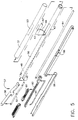
- Figure 5 is an exploded perspective view of the distal end of the cordless electrosurgical instrument illustrated in Figure 4.
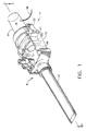
- FIG. 1 is a perspective view of an electrosurgical trocar according to the present invention.
- Electrosurgical trocar 11 includes trocar cannula 8 and electrosurgical adapter 14.
- Electrosurgical trocar 11 may also include an obturator assembly (not shown) such as the one illustrated in U.S. Patent 5,387,197, which has been previously incorporated herein by reference.
- Trocar cannula 8 includes cannula housing 12 and cannula tube 10, extending from housing 12.
- Electrosurgical adapter 14 includes an adapter housing 15, locking connector 17 and an electric cord 18.
- electrosurgical adapter 14 is connected to trocar cannula 8 by locking connector 17.
- Locking connector 17 includes locking cleat 20 and release button 22. It will be apparent that electrosurgical adapter 14 may be integrated directly into trocar cannula 8, thus eliminating the need for locking connector 17.
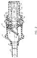
- FIG. 2 is a plan view section taken through electrosurgical trocar 11.
- cannula housing 12 includes flapper valve 34 and ring gasket 35.
- Electrosurgical adapter 14 includes central aperture 19, front flange 25 and base flange 24.
- Aperture 19 is an elongated aperture for receiving working instruments such as endoscopic electrosurgical instruments.
- Electrosurgical adapter 14 further includes a plurality of interior electrical contacts which, in the embodiment illustrated in Figures 2 and 3, comprise stator plates 28 and 29. At least a portion of the interior wall of central aperture 19 is formed by upper insulator 30 and upper stator plate 28.
- Upper insulator 30 is positioned against front flange 25 and base flange 24.
- Compression member 32 is, in the present embodiment, an o-ring which is positioned outside of upper insulator 30 to bias upper insulator 30 and upper stator plate 28 toward the center of central aperture 19.
- Compression member 32 may also be, for example, a spring, a flexible sleeve, a plurality of o-rings or any other suitable biasing member.
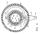
- FIG. 3 is a sectional view of electrosurgical adapter 14 taken along line 3-3 of Figure 2.
- Central aperture 19 is defined by aperture interior wall 21.
- the portion of interior wall 21 visible in Figure 3 is formed, at least in part, by upper contact surface 60 of upper stator plate 28 and lower contact surface 61 of lower stator plate 29.
- Upper stator plate 28 and lower stator plate 29 are positioned on, and electrically insulated from one another by, upper insulator 30 and lower insulator 31, respectively.
- Compression member 32 surrounds upper insulator 30 and lower insulator 31.
- Compression member 32 which is an o-ring in the embodiment of Figures 2-3, biases upper insulator 30 and lower insulator 31 toward the center of central aperture 19.
- Electric cord 18 is connected to upper stator plate 28 by upper conductor 36 and upper stator tab 26. Electric cord 18 is connected to lower stator plate 29 by lower conductor 38 and lower stator tab 27.
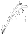
- FIG 4 is a perspective view of a cordless electrosurgical instrument which may be, for example, a bipolar cutter/stapler.
- electrosurgical instrument 16 includes handle 72, closure tube 50 and bipolar end effector 57.
- Closure tube 50 is elongated to facilitate insertion of end effector 57 through a trocar cannula, thus facilitating the use of electrosurgical instrument 16 in endoscopic or laparoscopic surgical procedures.
- Handle 72 which is located at the proximal end of instrument 16, includes grasping trigger 74, firing trigger 76 and release trigger 78.
- Closure tube 50 which connects handle 72 to end effector 57, includes rotation knob 70, first contact insulator 40, first instrument electrode contact 42, second instrument electrode contact 43 and outer tube 51.
- Electrosurgical instrument 16 is similar in structure and operation to the bipolar endoscopic electrocautery linear cutting and stapling instrument illustrated and described in U.S. Patent No. 5,403,312, which has been previously incorporated herein by reference. However electrosurgical instrument 16 is cordless. In electrosurgical instrument 16, electrosurgical energy is supplied to the instrument through first instrument electrode contact 42 and second instrument electrode contact 43.
- FIG 5 is an exploded perspective view of the in the distal end of electrosurgical instrument 16.
- outer tube 51 is positioned over closure tube 50.
- closure tube 50 is electrically conductive and outer tube 51 is constructed of an electrically insulating material.
- closure tube 50 is electrically conductive and outer tube 51 is constructed of an electrically insulating material.
- First instrument electrode contact 42 which penetrates first contact insulator 40, extends through opening 53 in outer tube 51.
- First contact insulator 40 electrically isolates contact 42 from closure tube 50.
- Second instrument electrode contact 43 which is connected to and in electrical contact with closure tube 50, extends through a second opening (not shown) in outer tube 51.
- contact 43 could be connected to an electrode on end effector 57 by an insulated wire which runs through closure tube 50 and, in such an instrument, closure tube 50 may be constructed of an insulating material.
- Conductor 48 passes through closure tube 51 from electrode assembly 52 to first instrument electrode contact 42, electrically connecting electrode assembly 52 to contact 42. Electrode assembly 52 is positioned in anvil 58. Electrode assembly 52 may be electrically insulated from anvil 58 and closure tube 50 to prevent electrode assembly 52 from shorting to anvil 58 or closure tube 50.
- Conductor 48 may be insulated to prevent it from shorting with closure tube 50 or any of the mechanism in closure tube 50.
- knife 90 is connected to wedge block assembly 82 and wedge block assembly 82 is connected to firing rod 84, which, in turn, is operatively connected to firing trigger 76.
- Closure tube 50 is operatively connected to rotation knob 70, grasping trigger 74 and release trigger 78.
- Wedge guide 80 is fitted over wedge block assembly 82 to guide wedge block assembly 82 as firing rod 84 moves wedge block assembly 82.
- cartridge channel 88 and closure tube 50 are electrically conductive and in electrical contact.
- cartridge channel 88 acts as a second or return electrode.
- trocar cannula 8 is used with a conventional trocar obturator (not shown) to penetrate the wall of a body cavity such as, for example, the abdominal wall of a human being. After the body wall is penetrated, the obturator assembly is withdrawn from trocar cannula 8, and the cannula is used as an access portal for the passage of various endoscopic instruments to provide access to internal organs.
- the endoscopic instrument to be used is a cordless electrosurgical instrument such as electrosurgical instrument 16
- electrosurgical adapter 14 may be attached to trocar cannula 8.
- electrosurgical adapter 14 Once electrosurgical adapter 14 is attached to trocar cannula 8 and electric cord 18 is attached to a suitable electrosurgical generator (not shown), electrosurgical trocar 11 may be used to provide electrosurgical energy to cordless electrosurgical instruments such as electrosurgical instrument 16.
- end effector 57 passes through cannula 8 and into the body cavity while most of closure tube 50 remains in the trocar.
- Handle 72 which is outside of trocar 11, is manipulated by the surgeon to control the position of end effector 57.
- Electrosurgical energy is provided to instrument 16 by the interaction of contact 42 and contact 43 with the stator plates 28 and 29.
- the diameter of central aperture 19 generally corresponds with the outer diameter of closure tube 50, including outer tube 51, so that closure tube 50 slides through central aperture 19 and the interior of cannula tube 10.
- Contact 42 and contact 43 being raised above the surface of closure tube 50 and outer tube 51, will scrape against stator plates 28 and 29 as closure tube 50 passes through aperture 19.
- Compression member 32 will ensure that stator plates 28 and 29 maintain contact with contacts 42 and 43, maintaining a good electrical connection between the stator plates in adapter 14 and the contact points on instrument 16. Electrical contact will be maintained so long as contacts 42 and 43 are positioned in central aperture 19 opposite stator plates 28 and 29.
- electrosurgical energy may be supplied to electrosurgical trocar 11 through electric cord 18.
- the electrosurgical energy passes through conductors 36 and 38, stator tabs 26 and 27 and stator plates 28 and 29 into instrument 16 via contacts 42 and 43.
- Electrosurgical energy supplied to instrument 16 via contacts 42 and 43 may be supplied to end effector 57 via the circuit formed by first instrument electrode contact 42, conductor 48, electrode assembly 52, cartridge channel 88, closure tube 50 and second instrument electrode contact 43. This circuit is completed when tissue or other conductive tissue is grasped by end effector 57, providing a path from electrode assembly 52 to cartridge channel 88.
Description
- The present invention relates, in general, to an improved electrosurgical instrument and method of use and, more particularly, to an electrosurgical trocar adapted to provide electrosurgical energy to specially adapted cordless electrosurgical instruments used with the electrosurgical trocar and to a method of using such a trocar and associated instruments.
- The surgical trocar has become the mainstay in the development and acceptance of endoscopic surgical procedures. Endoscopic surgery involves the performance of surgery through a number of openings having a relatively small diameter. These openings are made with the trocar, which typically includes a trocar obturator and a trocar cannula. The obturator is the piercing implement which punctures the body wall to make the opening. Once the puncture is made, the obturator is withdrawn from the cannula. The cannula then provides a small diameter passageway into and through the body wall to provide access for additional surgical instrumentation to the surgical site. The function, structure and operation of a typical trocar is described in detail in U.S. Patent 5,387,197, which is hereby incorporated herein by reference.
- Electrosurgical trocars are also known. For example, see U.S. Patent 5,599,348. With thus device, an electrosurgical cutting element makes a guide hole for the cannula of the trocar to push through.
- Such additional surgical instruments may include, for example, bipolar or monopolar electrosurgical instruments which utilize radio frequency electrosurgical energy. Known electrosurgical instruments include, for example, bipolar forceps, bipolar scissors, monopolar-hook monopolar-scissors and, bipolar endocutters. Each of those instruments has an electrosurgical end effector which is adapted to treat tissue through the application of electrosurgical (e.g. radio frequency or RF) energy to tissue which is brought in contact with the electrosurgical end effector. Most known electrosurgical instruments are connected by electrical cords to electrosurgical generators. The structure and operation of a typical bipolar cutter/stapler ("bipolar endocutter") is described in U.S. Patent No. 5,403,312 which is hereby incorporated herein by reference.
- Electrosurgical generators, such as the Force II generator which is available from Valleylab of Bolder Colorado, supply electrical energy to the electrosurgical instruments through electrical cords. The electrical cords, being attached directly to the electrosurgical instrument, may make the electrosurgical instrument inconvenient to use. Alternatively, electrical cords may cause undesirable delays as one electrosurgical instrument is unplugged from the generator and another is plugged in. Thus, it would be advantageous to design a cordless electrosurgical instrument. However, such a cordless electrosurgical instrument would have to be connected to the electrosurgical generator through some alternate arrangement. Therefore, it would also be advantageous to design a trocar or a trocar adapter which is adapted to conduct electrosurgical energy to specially designed cordless electrosurgical instruments.
- The present invention provides an electrosurgical trocar as defined in claim 1, an electrosurgical adapter as defined in claim 7 and methods of supplying electrosurgical energy to a cardless electrosurgical instrument as defined in
claims 9 and 10. - In the present invention, a surgical trocar is adapted to conduct electrosurgical energy to specially adapted cordless electrosurgical instruments. In one embodiment of the present invention, an electrosurgical trocar includes a cannula, an electrosurgical adapter and a locking connector adapted to connect the cannula to the electrosurgical adapter. The cannula is an elongated tube which may be inserted into a body cavity, duct or vessel. The electrosurgical adapter includes a housing with an elongated central aperture, first and second electrical contacts positioned in and extending axially along the elongated aperture, first and second electrical conductors, first and second external conductors, a compression mechanism, an outer housing and an electrical cord.
- In a further embodiment of the present invention, the adapter aperture is formed by an aperture wall positioned in the adapter housing. The first and second electrical contacts are positioned in and extend axially along the aperture, forming at least a portion of the walls of the aperture. The first and second electrical conductors connect the first and second electrical contacts to the first and second external connectors. The compression mechanism biases the first and second electrical contacts toward the center of the adapter aperture. An electrical cord is connected to the first and second external connectors such that the electrical cord may be used to plug the adapter into an electrosurgical generator.
- In a further embodiment of the present invention, the first electrical contact is a first stator plate and the second electrical contact is a second stator plate. The second stator plate is positioned opposite the first stator plate. The second stator plate is electrically insulated from the first stator plate. The compression member includes one or more compression rings positioned around the first and second electrical contacts.
- In a further embodiment of the present invention, the electrosurgical trocar includes a locking connector which connects the cannula to the adapter. In this embodiment of the invention, the adapter includes first and second locking cleats extending from the distal end of the connector. The cannula includes receptors such as indentations or ribs which hold the distal ends of the locking cleats in place, thus holding the adapter in contact with the cannula.
- The novel features of the invention are set forth with particularity in the appended claims. The invention itself, however, both as to organization and methods of operation, together with further objects and advantages thereof, may best be understood by reference to the following description, taken in conjunction with the accompanying drawings in which:
- Figure 1 is a perspective view of an electrosurgical trocar according to the present invention.
- Figure 2 is a plan view section taken through the electrosurgical trocar illustrated in Figure 1.
- Figure 3 is a section view taken along line 3-3 of Figure 2.
- Figure 4 is a perspective view of a cordless electrosurgical instrument according to the present invention.
- Figure 5 is an exploded perspective view of the distal end of the cordless electrosurgical instrument illustrated in Figure 4.
- Figure 1 is a perspective view of an electrosurgical trocar according to the present invention.
Electrosurgical trocar 11 includes trocarcannula 8 andelectrosurgical adapter 14.Electrosurgical trocar 11 may also include an obturator assembly (not shown) such as the one illustrated in U.S. Patent 5,387,197, which has been previously incorporated herein by reference. Trocarcannula 8 includescannula housing 12 andcannula tube 10, extending fromhousing 12.Electrosurgical adapter 14 includes anadapter housing 15,locking connector 17 and anelectric cord 18. In the embodiment of the invention illustrated in Figure 1,electrosurgical adapter 14 is connected to trocarcannula 8 bylocking connector 17.Locking connector 17 includeslocking cleat 20 andrelease button 22. It will be apparent thatelectrosurgical adapter 14 may be integrated directly intotrocar cannula 8, thus eliminating the need forlocking connector 17. - Figure 2 is a plan view section taken through
electrosurgical trocar 11. In Figure 2,cannula housing 12 includesflapper valve 34 andring gasket 35.Electrosurgical adapter 14 includescentral aperture 19,front flange 25 andbase flange 24. Aperture 19 is an elongated aperture for receiving working instruments such as endoscopic electrosurgical instruments.Electrosurgical adapter 14 further includes a plurality of interior electrical contacts which, in the embodiment illustrated in Figures 2 and 3, comprisestator plates central aperture 19 is formed byupper insulator 30 andupper stator plate 28.Upper insulator 30 is positioned againstfront flange 25 andbase flange 24.Compression member 32 is, in the present embodiment, an o-ring which is positioned outside ofupper insulator 30 to biasupper insulator 30 andupper stator plate 28 toward the center ofcentral aperture 19.Compression member 32 may also be, for example, a spring, a flexible sleeve, a plurality of o-rings or any other suitable biasing member. - Figure 3 is a sectional view of
electrosurgical adapter 14 taken along line 3-3 of Figure 2.Central aperture 19 is defined by apertureinterior wall 21. The portion ofinterior wall 21 visible in Figure 3 is formed, at least in part, byupper contact surface 60 ofupper stator plate 28 andlower contact surface 61 oflower stator plate 29.Upper stator plate 28 andlower stator plate 29 are positioned on, and electrically insulated from one another by,upper insulator 30 andlower insulator 31, respectively.Compression member 32 surroundsupper insulator 30 andlower insulator 31.Compression member 32, which is an o-ring in the embodiment of Figures 2-3, biasesupper insulator 30 andlower insulator 31 toward the center ofcentral aperture 19.Electric cord 18 is connected toupper stator plate 28 byupper conductor 36 andupper stator tab 26.Electric cord 18 is connected tolower stator plate 29 bylower conductor 38 andlower stator tab 27.Base flange 24, which is part ofadapter housing 15, holdsupper insulator 30 andlower insulator 31 in place.Strain relief 23 protectselectric cord 18 as it passes throughadapter housing 15. - Figure 4 is a perspective view of a cordless electrosurgical instrument which may be, for example, a bipolar cutter/stapler. In Figure 4,
electrosurgical instrument 16 includeshandle 72,closure tube 50 andbipolar end effector 57.Closure tube 50 is elongated to facilitate insertion ofend effector 57 through a trocar cannula, thus facilitating the use ofelectrosurgical instrument 16 in endoscopic or laparoscopic surgical procedures.Handle 72, which is located at the proximal end ofinstrument 16, includes graspingtrigger 74, firingtrigger 76 andrelease trigger 78.Closure tube 50, which connects handle 72 to endeffector 57, includesrotation knob 70,first contact insulator 40, firstinstrument electrode contact 42, secondinstrument electrode contact 43 andouter tube 51.End effector 57, which is located at the distal end ofclosure tube 50 includesanvil 58 andcartridge channel 88.Electrosurgical instrument 16 is similar in structure and operation to the bipolar endoscopic electrocautery linear cutting and stapling instrument illustrated and described in U.S. Patent No. 5,403,312, which has been previously incorporated herein by reference. Howeverelectrosurgical instrument 16 is cordless. Inelectrosurgical instrument 16, electrosurgical energy is supplied to the instrument through firstinstrument electrode contact 42 and secondinstrument electrode contact 43. - Figure 5 is an exploded perspective view of the in the distal end of
electrosurgical instrument 16. In Figure 5,outer tube 51 is positioned overclosure tube 50. In the instruments illustrated in Figures 4 and 5,closure tube 50 is electrically conductive andouter tube 51 is constructed of an electrically insulating material. In the instruments illustrated in Figures 4 and 5,closure tube 50 is electrically conductive andouter tube 51 is constructed of an electrically insulating material. Firstinstrument electrode contact 42, which penetratesfirst contact insulator 40, extends through opening 53 inouter tube 51.First contact insulator 40 electrically isolates contact 42 fromclosure tube 50. Secondinstrument electrode contact 43 which is connected to and in electrical contact withclosure tube 50, extends through a second opening (not shown) inouter tube 51. In an alternate electrosurgical instrument, contact 43 could be connected to an electrode onend effector 57 by an insulated wire which runs throughclosure tube 50 and, in such an instrument,closure tube 50 may be constructed of an insulating material.Conductor 48 passes throughclosure tube 51 fromelectrode assembly 52 to firstinstrument electrode contact 42, electrically connectingelectrode assembly 52 to contact 42.Electrode assembly 52 is positioned inanvil 58.Electrode assembly 52 may be electrically insulated fromanvil 58 andclosure tube 50 to preventelectrode assembly 52 from shorting toanvil 58 orclosure tube 50.Conductor 48 may be insulated to prevent it from shorting withclosure tube 50 or any of the mechanism inclosure tube 50. - In the cordless electrosurgical instrument illustrated in Figures 4 and 5,
knife 90 is connected to wedgeblock assembly 82 andwedge block assembly 82 is connected to firing rod 84, which, in turn, is operatively connected to firingtrigger 76.Closure tube 50 is operatively connected torotation knob 70, graspingtrigger 74 andrelease trigger 78. Wedge guide 80 is fitted overwedge block assembly 82 to guidewedge block assembly 82 as firing rod 84 moveswedge block assembly 82. The structure and operation of the mechanical features of the device illustrated in Figures 4 and 5 may be better understood with reference to the mechanical cutting and stapling instrument illustrated and described in U.S. Patent No. 5,597,107 which is hereby incorporated herein by reference. - In the device illustrated in Figures 4 and 5,
cartridge channel 88 andclosure tube 50 are electrically conductive and in electrical contact. Thus, whereelectrode assembly 52 acts as a primary electrode,cartridge channel 88 acts as a second or return electrode. When electrically conductive tissue is grasped byend effector 57 and an electrosurgical generator is connected to firstinstrument electrode contact 42 and secondinstrument electrode contact 43, electrosurgical energy will flow through the grasped tissue, coagulating the grasped tissue. - In operation,
trocar cannula 8 is used with a conventional trocar obturator (not shown) to penetrate the wall of a body cavity such as, for example, the abdominal wall of a human being. After the body wall is penetrated, the obturator assembly is withdrawn fromtrocar cannula 8, and the cannula is used as an access portal for the passage of various endoscopic instruments to provide access to internal organs. Where the endoscopic instrument to be used is a cordless electrosurgical instrument such aselectrosurgical instrument 16,electrosurgical adapter 14 may be attached totrocar cannula 8. Onceelectrosurgical adapter 14 is attached totrocar cannula 8 andelectric cord 18 is attached to a suitable electrosurgical generator (not shown),electrosurgical trocar 11 may be used to provide electrosurgical energy to cordless electrosurgical instruments such aselectrosurgical instrument 16. - When a cordless electrosurgical instrument such as
electrosurgical instrument 16 is inserted into a body cavity throughelectrosurgical trocar 11,end effector 57 passes throughcannula 8 and into the body cavity while most ofclosure tube 50 remains in the trocar.Handle 72, which is outside oftrocar 11, is manipulated by the surgeon to control the position ofend effector 57. - Electrosurgical energy is provided to
instrument 16 by the interaction ofcontact 42 andcontact 43 with thestator plates central aperture 19 generally corresponds with the outer diameter ofclosure tube 50, includingouter tube 51, so thatclosure tube 50 slides throughcentral aperture 19 and the interior ofcannula tube 10.Contact 42 andcontact 43, being raised above the surface ofclosure tube 50 andouter tube 51, will scrape againststator plates closure tube 50 passes throughaperture 19.Compression member 32 will ensure thatstator plates contacts adapter 14 and the contact points oninstrument 16. Electrical contact will be maintained so long ascontacts central aperture 19opposite stator plates - With
contacts stator plates electrosurgical trocar 11 throughelectric cord 18. The electrosurgical energy passes throughconductors stator tabs stator plates instrument 16 viacontacts instrument 16 viacontacts effector 57 via the circuit formed by firstinstrument electrode contact 42,conductor 48,electrode assembly 52,cartridge channel 88,closure tube 50 and secondinstrument electrode contact 43. This circuit is completed when tissue or other conductive tissue is grasped byend effector 57, providing a path fromelectrode assembly 52 tocartridge channel 88. - While preferred embodiments of the present invention have been shown and described herein, it will be obvious to those skilled in the art that such embodiments are provided by way of example only. Numerous variations, changes, and substitutions will now occur to those skilled in the art without departing from the invention. Accordingly, it is intended that the invention be limited only by the scope of the appended claims.
Claims (10)
- An electrosurgical trocar (11) comprising:a) an elongated central aperture (19) extending from the first end of said trocar (11) to a second end of said trocar (11), wherein said first aperture (19) is surrounded by an aperture wall;b) first and second electrical contact means (28,29) positioned in and extending axially along said elongated aperture (19);c) a first electrical conductor (26) connecting said first electrical contact means (28) to a first external connector (36);d) a second electrical conductor (27) connecting said second electrical contact means (29) to a second external connector (38);e) a compression means (32) adapted to bias said first and second electrical contact means (28,29) towards the center of said aperture (19);f) an outer housing (15) surrounding said aperture (19) and said first and second electrical contact means (28,29); andg) an electrical cord (18) connected to said first and second external connectors (36,38) and extending from said outer housing (15).
- The electrosurgical trocar (11) of claim 1, wherein the elongated central aperture (19) has a central axis extending from the first end of said trocar to the second end of said trocar (11).
- The electrosurgical trocar (11) of claim 1 or claim 2, connectable to an external source of electrical energy.
- An electrosurgical trocar (11) according to claim 1, claim 2 or claim 3, wherein said first and second electrical contact means (28,29) comprise:a) a first stator plate (28), wherein said first stator plate (28) comprises a first portion of said aperture wall;b) a second stator plate (29) electrically insulated from said first stator plate (28), wherein said second stator plate (29) comprises a second portion of said aperture wall opposite said first portion.
- An electrosurgical trocar (11) according to claim 4, wherein said compression means comprises a compression member (32) surrounding said stator plates (28,29).
- The electrosurgical trocar (11) of any preceding claim, wherein said compression means comprises one or more compression rings.
- An electrosurgical adapter (14) comprising:a) an elongated central aperture (19) including a central axis extending from the first end of said adapter (14) to a second end of said adapter (14), wherein said first aperture (19) is surrounded by an aperture wall;b) first and second electrical contact means (28,29) for providing electrical energy to instruments positionable in said aperture (19), wherein said first and second electrical contact means (28,29) are positioned in and extend axially along said elongated aperture (19), wherein said first and second electrical contact means (28,29) comprise:i) a first stator plate (28), wherein said first stator plate (28) comprises a first portion of said aperture wall;ii) a second stator plate (29) electrically insulated from said first stator plate (28), wherein said second stator plate (29) comprises a second portion of said aperture wall opposite said first portion;c) a first electrical conductor (26) connecting said first electrical contact means (28) to a first external connector means (36) for connecting said first electrical conductor (26) to an external source of electrical energy;d) a second electrical conductor (27) connecting said second electrical contact means (29) to a second external connector means (38) for connecting said second electrical conductor (27) to an external source of electrical energy;e) a compression means (32) adapted to bias said first and second stator plates (28,29) towards said central axis of said aperture (19), said compression means comprising:i) a compression member (32) surrounding said stator plates (28,29), wherein said compression member (32) comprises one or more compression rings;f) an outer housing (15) surrounding said aperture (19) and said first and second electrical contact means (28,29); andg) an electrical cord (18) connected to said first and second external connector means (36,38) and extending from said outer housing (15).
- An electrosurgical trocar (11) comprising:a) a cannula (8);b) an electrosurgical adapter (14) according to claim 7;c) a locking connector (17) adapted to connect said cannula (8) to said adapter (14), wherein said locking connector (17) comprises:i) first and second locking cleats (20) extending from said first end of said adapter (14); andii) first and second indentations on said cannula (8).
- A method of supplying electrosurgical energy to a cordless electrosurgical instrument (16), wherein said method comprises the steps of:a) inserting said cordless electrosurgical instrument (16) into an electrosurgical trocar (11) according to any one of claims 1 to 6 or 8;b) connecting said electrosurgical trocar (11) to a source of electrosurgical energy; andc) turning on said source of electrosurgical energy.
- A method of supplying electrosurgical energy to a cordless electrosurgical instrument (16), wherein said method comprises the steps of:a) inserting said cordless electrosurgical instrument (16) into an electrosurgical adapter (14) according to claim 7;b) connecting said electrosurgical adapter (14) to a source of electrosurgical energy; andc) turning on said source of electrosurgical energy.
Applications Claiming Priority (2)
| Application Number | Priority Date | Filing Date | Title |
|---|---|---|---|
| US08/856,534 US5984921A (en) | 1997-05-14 | 1997-05-14 | Method and apparatus for applying electrical energy to medical instruments |
| US856534 | 1997-05-14 |
Publications (2)
| Publication Number | Publication Date |
|---|---|
| EP0878877A1 EP0878877A1 (en) | 1998-11-18 |
| EP0878877B1 true EP0878877B1 (en) | 2002-01-16 |
Family
ID=25323877
Family Applications (1)
| Application Number | Title | Priority Date | Filing Date |
|---|---|---|---|
| EP98303754A Expired - Lifetime EP0878877B1 (en) | 1997-05-14 | 1998-05-13 | Method and apparatus for applying electrical energy to medical instruments |
Country Status (7)
| Country | Link |
|---|---|
| US (3) | US5984921A (en) |
| EP (1) | EP0878877B1 (en) |
| JP (1) | JP4137232B2 (en) |
| AU (1) | AU730322B2 (en) |
| CA (1) | CA2237420C (en) |
| DE (1) | DE69803141T2 (en) |
| ES (1) | ES2167048T3 (en) |
Families Citing this family (53)
| Publication number | Priority date | Publication date | Assignee | Title |
|---|---|---|---|---|
| US6106519A (en) * | 1997-06-30 | 2000-08-22 | Ethicon Endo-Surgery, Inc. | Capacitively coupled electrosurgical trocar |
| US6096037A (en) * | 1997-07-29 | 2000-08-01 | Medtronic, Inc. | Tissue sealing electrosurgery device and methods of sealing tissue |
| US6511512B2 (en) * | 1998-04-10 | 2003-01-28 | Ossur Hf | Active shock module prosthesis |
| US6471659B2 (en) | 1999-12-27 | 2002-10-29 | Neothermia Corporation | Minimally invasive intact recovery of tissue |
| US6206852B1 (en) * | 1999-12-15 | 2001-03-27 | Advanced Cardiovascular Systems, Inc. | Balloon catheter having a small profile catheter |
| US6277083B1 (en) | 1999-12-27 | 2001-08-21 | Neothermia Corporation | Minimally invasive intact recovery of tissue |
| US6447443B1 (en) * | 2001-01-13 | 2002-09-10 | Medtronic, Inc. | Method for organ positioning and stabilization |
| US20010042702A1 (en) * | 2000-04-17 | 2001-11-22 | Stuntz Gordon F. | Cycle oil conversion process |
| US6546935B2 (en) | 2000-04-27 | 2003-04-15 | Atricure, Inc. | Method for transmural ablation |
| US20020107514A1 (en) * | 2000-04-27 | 2002-08-08 | Hooven Michael D. | Transmural ablation device with parallel jaws |
| US6488680B1 (en) | 2000-04-27 | 2002-12-03 | Medtronic, Inc. | Variable length electrodes for delivery of irrigated ablation |
| US6942671B1 (en) * | 2000-11-06 | 2005-09-13 | Tyco Healthcare Group Lp | Surgical sealing apparatus |
| US7628780B2 (en) * | 2001-01-13 | 2009-12-08 | Medtronic, Inc. | Devices and methods for interstitial injection of biologic agents into tissue |
| US20040138621A1 (en) * | 2003-01-14 | 2004-07-15 | Jahns Scott E. | Devices and methods for interstitial injection of biologic agents into tissue |
| US7740623B2 (en) * | 2001-01-13 | 2010-06-22 | Medtronic, Inc. | Devices and methods for interstitial injection of biologic agents into tissue |
| US6551312B2 (en) | 2001-03-09 | 2003-04-22 | Quantum Cor, Inc. | Wireless electrosurgical device and methods thereof |
| WO2003015848A1 (en) * | 2001-08-14 | 2003-02-27 | Applied Medical Resources Corporation | Access sealing apparatus and method |
| US7967816B2 (en) | 2002-01-25 | 2011-06-28 | Medtronic, Inc. | Fluid-assisted electrosurgical instrument with shapeable electrode |
| US7632250B2 (en) | 2002-05-10 | 2009-12-15 | Tyco Healthcare Group Lp | Introducer seal assembly |
| US20040066008A1 (en) * | 2002-10-04 | 2004-04-08 | Smith Robert C. | Introducer seal assembly |
| US7128741B1 (en) | 2003-04-04 | 2006-10-31 | Megadyne Medical Products, Inc. | Methods, systems, and devices for performing electrosurgical procedures |
| CA2533204A1 (en) | 2003-08-06 | 2005-02-17 | Applied Medical Resources Corporation | Surgical device with tack-free gel and method of manufacture |
| US20050187545A1 (en) * | 2004-02-20 | 2005-08-25 | Hooven Michael D. | Magnetic catheter ablation device and method |
| US7530980B2 (en) * | 2004-04-14 | 2009-05-12 | Atricure, Inc | Bipolar transmural ablation method and apparatus |
| WO2005120376A2 (en) * | 2004-06-02 | 2005-12-22 | Medtronic, Inc. | Ablation device with jaws |
| US7608082B2 (en) * | 2005-01-06 | 2009-10-27 | Tyco Healthcare Group Lp | Surgical seal for use in a surgical access apparatus |
| US20090018174A1 (en) * | 2005-11-08 | 2009-01-15 | Pradip Kumar Bhatnagar | Macrolides as anti-inflammatory agents |
| CN103352810B (en) * | 2006-03-07 | 2016-07-06 | 芙罗服务管理公司 | Generate electricity for valve acutator |
| DE112006003797B4 (en) | 2006-03-07 | 2015-10-22 | Flowserve Management Company | Power generation for valve actuators |
| US8932275B2 (en) * | 2006-07-07 | 2015-01-13 | Covidien Lp | Surgical seal assembly |
| US7918827B2 (en) * | 2007-09-25 | 2011-04-05 | Tyco Healthcare Group Lp | Seal assembly for surgical access device |
| US20090105635A1 (en) * | 2007-10-17 | 2009-04-23 | Tyco Healthcare Group Lp | Access assembly with seal lubricant mechanism |
| US8758342B2 (en) | 2007-11-28 | 2014-06-24 | Covidien Ag | Cordless power-assisted medical cauterization and cutting device |
| US8377059B2 (en) | 2007-11-28 | 2013-02-19 | Covidien Ag | Cordless medical cauterization and cutting device |
| US9050098B2 (en) | 2007-11-28 | 2015-06-09 | Covidien Ag | Cordless medical cauterization and cutting device |
| US8491581B2 (en) * | 2008-03-19 | 2013-07-23 | Covidien Ag | Method for powering a surgical instrument |
| US8328802B2 (en) * | 2008-03-19 | 2012-12-11 | Covidien Ag | Cordless medical cauterization and cutting device |
| EP2319447B1 (en) | 2008-03-31 | 2012-08-22 | Applied Medical Resources Corporation | Electrosurgical tool with jaws actuatable by a force regulation mechanism |
| US20090270819A1 (en) * | 2008-04-29 | 2009-10-29 | Dario Vitali | Optical safety trocar and method of use thereof |
| US9028448B2 (en) * | 2008-06-19 | 2015-05-12 | Covidien Lp | Access seal with interstitial channels |
| US9782217B2 (en) | 2008-11-13 | 2017-10-10 | Covidien Ag | Radio frequency generator and method for a cordless medical cauterization and cutting device |
| US9681813B2 (en) | 2009-07-29 | 2017-06-20 | Dinnos Technology | Neurophysiological stimulation system and methods with wireless communication |
| ES2664081T3 (en) | 2010-10-01 | 2018-04-18 | Applied Medical Resources Corporation | Electrosurgical system with a radio frequency amplifier and with means for adapting to the separation between electrodes |
| EP2996758A4 (en) * | 2013-03-15 | 2016-09-28 | Intuitive Surgical Operations | Rotating assistant port |
| WO2015095281A1 (en) * | 2013-12-17 | 2015-06-25 | The Trustees Of The University Of Pennsylvania | Apparatus, system and method for preventing retention of surgical drains |
| JP6573663B2 (en) | 2014-05-16 | 2019-09-11 | アプライド メディカル リソーシーズ コーポレイション | Electrosurgical system |
| AU2015266619B2 (en) | 2014-05-30 | 2020-02-06 | Applied Medical Resources Corporation | Electrosurgical instrument for fusing and cutting tissue and an electrosurgical generator |
| EP3236870B1 (en) | 2014-12-23 | 2019-11-06 | Applied Medical Resources Corporation | Bipolar electrosurgical sealer and divider |
| USD748259S1 (en) | 2014-12-29 | 2016-01-26 | Applied Medical Resources Corporation | Electrosurgical instrument |
| CN107205755A (en) * | 2015-02-27 | 2017-09-26 | 奥林巴斯株式会社 | Medical feed system |
| US11058477B2 (en) * | 2017-06-28 | 2021-07-13 | Cilag Gmbh International | Surgical cutting and fastening instruments with dual power sources |
| CA3111558A1 (en) | 2018-09-05 | 2020-03-12 | Applied Medical Resources Corporation | Electrosurgical generator control system |
| US11696796B2 (en) | 2018-11-16 | 2023-07-11 | Applied Medical Resources Corporation | Electrosurgical system |
Family Cites Families (35)
| Publication number | Priority date | Publication date | Assignee | Title |
|---|---|---|---|---|
| US1620929A (en) * | 1925-02-05 | 1927-03-15 | George W Wallerich | Heat-therapy method and means |
| US4535773A (en) * | 1982-03-26 | 1985-08-20 | Inbae Yoon | Safety puncturing instrument and method |
| GB8501155D0 (en) * | 1985-01-17 | 1985-02-20 | Shell Int Research | Capacitive underwater electrical connector |
| US4717438A (en) * | 1986-09-29 | 1988-01-05 | Monarch Marking Systems, Inc. | Method of making tags |
| US4936842A (en) * | 1987-05-08 | 1990-06-26 | Circon Corporation | Electrosurgical probe apparatus |
| US4799480A (en) * | 1987-08-04 | 1989-01-24 | Conmed | Electrode for electrosurgical apparatus |
| KR900006537B1 (en) * | 1987-10-19 | 1990-09-07 | 태림전자 주식회사 | Antenna assembly for car-phone |
| US4884982A (en) * | 1989-04-03 | 1989-12-05 | Amp Incorporated | Capacitive coupled connector |
| US5105829A (en) * | 1989-11-16 | 1992-04-21 | Fabian Carl E | Surgical implement detector utilizing capacitive coupling |
| US4934960A (en) * | 1990-01-04 | 1990-06-19 | Amp Incorporated | Capacitive coupled connector with complex insulative body |
| US5124509A (en) * | 1991-01-15 | 1992-06-23 | Calcomp, Inc. | Digitizer with capacitive and inductive coupling |
| EP0525172B1 (en) * | 1991-02-13 | 1999-09-01 | Applied Medical Resources, Inc. | Surgical trocar |
| US5391166A (en) * | 1991-06-07 | 1995-02-21 | Hemostatic Surgery Corporation | Bi-polar electrosurgical endoscopic instruments having a detachable working end |
| US5545142A (en) * | 1991-10-18 | 1996-08-13 | Ethicon, Inc. | Seal members for surgical trocars |
| US5437277A (en) * | 1991-11-18 | 1995-08-01 | General Electric Company | Inductively coupled RF tracking system for use in invasive imaging of a living body |
| US5300070A (en) * | 1992-03-17 | 1994-04-05 | Conmed Corporation | Electrosurgical trocar assembly with bi-polar electrode |
| GB9209859D0 (en) * | 1992-05-07 | 1992-06-24 | Smiths Industries Plc | Electrical apparatus |
| US5387196A (en) * | 1992-05-19 | 1995-02-07 | United States Surgical Corporation | Cannula assembly having conductive cannula |
| WO1994006510A1 (en) * | 1992-09-11 | 1994-03-31 | Advanced Surgical, Inc. | Self-introducing infusion catheter |
| US5380321A (en) * | 1992-11-04 | 1995-01-10 | Yoon; Inbae | Shielded energy transmitting surgical instrument and methods therefor |
| US5342357A (en) * | 1992-11-13 | 1994-08-30 | American Cardiac Ablation Co., Inc. | Fluid cooled electrosurgical cauterization system |
| DE4239625C1 (en) * | 1992-11-26 | 1993-08-05 | Fresenius Ag, 6380 Bad Homburg, De | Medical transfusion equipment connecting column - forms connection with data exchange equipment and has two conductors secured by clamp with jaws and electrical contacts |
| US5342356A (en) * | 1992-12-02 | 1994-08-30 | Ellman Alan G | Electrical coupling unit for electrosurgery |
| US5403312A (en) * | 1993-07-22 | 1995-04-04 | Ethicon, Inc. | Electrosurgical hemostatic device |
| US5387197A (en) * | 1993-02-25 | 1995-02-07 | Ethicon, Inc. | Trocar safety shield locking mechanism |
| US5383860A (en) * | 1993-03-02 | 1995-01-24 | M.I.S. Technology International, Inc. | Two-part conductive cannula with adaptive disposable non-invasive element |
| US5417687A (en) * | 1993-04-30 | 1995-05-23 | Medical Scientific, Inc. | Bipolar electrosurgical trocar |
| US5437643A (en) * | 1993-05-17 | 1995-08-01 | Ethicon, Inc. | Safety interposer for surgical instruments |
| US5432486A (en) * | 1993-05-20 | 1995-07-11 | Northern Telecom Limited | Capacitive and inductive coupling connector |
| US5597107A (en) * | 1994-02-03 | 1997-01-28 | Ethicon Endo-Surgery, Inc. | Surgical stapler instrument |
| US5445142A (en) * | 1994-03-15 | 1995-08-29 | Ethicon Endo-Surgery, Inc. | Surgical trocars having optical tips defining one or more viewing ports |
| US5540684A (en) * | 1994-07-28 | 1996-07-30 | Hassler, Jr.; William L. | Method and apparatus for electrosurgically treating tissue |
| US5591192A (en) * | 1995-02-01 | 1997-01-07 | Ethicon Endo-Surgery, Inc. | Surgical penetration instrument including an imaging element |
| US5733323A (en) * | 1995-11-13 | 1998-03-31 | Cordis Corporation | Electrically conductive unipolar vascular sheath |
| US5902264A (en) * | 1996-04-26 | 1999-05-11 | United States Surgical Corporation | Endoscopic surgical instrument for aspiration and irrigation |
-
1997
- 1997-05-14 US US08/856,534 patent/US5984921A/en not_active Expired - Lifetime
-
1998
- 1998-05-11 AU AU64871/98A patent/AU730322B2/en not_active Ceased
- 1998-05-12 CA CA002237420A patent/CA2237420C/en not_active Expired - Fee Related
- 1998-05-13 EP EP98303754A patent/EP0878877B1/en not_active Expired - Lifetime
- 1998-05-13 JP JP14836898A patent/JP4137232B2/en not_active Expired - Fee Related
- 1998-05-13 DE DE69803141T patent/DE69803141T2/en not_active Expired - Lifetime
- 1998-05-13 ES ES98303754T patent/ES2167048T3/en not_active Expired - Lifetime
-
1999
- 1999-03-18 US US09/271,775 patent/US6030403A/en not_active Expired - Lifetime
- 1999-03-18 US US09/271,525 patent/US6120501A/en not_active Expired - Lifetime
Also Published As
| Publication number | Publication date |
|---|---|
| DE69803141T2 (en) | 2002-07-11 |
| DE69803141D1 (en) | 2002-02-21 |
| CA2237420C (en) | 2006-11-21 |
| AU6487198A (en) | 1998-11-19 |
| US6120501A (en) | 2000-09-19 |
| EP0878877A1 (en) | 1998-11-18 |
| US5984921A (en) | 1999-11-16 |
| US6030403A (en) | 2000-02-29 |
| AU730322B2 (en) | 2001-03-01 |
| JP4137232B2 (en) | 2008-08-20 |
| ES2167048T3 (en) | 2002-05-01 |
| CA2237420A1 (en) | 1998-11-14 |
| JPH1170117A (en) | 1999-03-16 |
Similar Documents
| Publication | Publication Date | Title |
|---|---|---|
| EP0878877B1 (en) | Method and apparatus for applying electrical energy to medical instruments | |
| EP0885597B1 (en) | Cordless electrosurgical instrument, and relevant trokar | |
| EP0888747B1 (en) | Capacitively coupled electrosurgical trocar | |
| EP0888749B1 (en) | Capacitively coupled cordless electrosurgical instrument | |
| US5849020A (en) | Inductively coupled electrosurgical instrument | |
| EP0888748B1 (en) | Electrosurgical trocar comprising inductive adapter | |
| EP0885596B1 (en) | Monopolar electrosurgical trocar |
Legal Events
| Date | Code | Title | Description |
|---|---|---|---|
| PUAI | Public reference made under article 153(3) epc to a published international application that has entered the european phase |
Free format text: ORIGINAL CODE: 0009012 |
|
| AK | Designated contracting states |
Kind code of ref document: A1 Designated state(s): DE ES FR GB IT NL |
|
| AX | Request for extension of the european patent |
Free format text: AL;LT;LV;MK;RO;SI |
|
| RIN1 | Information on inventor provided before grant (corrected) |
Inventor name: KNODEL, BRYAN D. Inventor name: FREEMAN, LYNETTA J. Inventor name: LONG, GARY L. |
|
| 17P | Request for examination filed |
Effective date: 19990430 |
|
| AKX | Designation fees paid |
Free format text: DE ES FR GB IT NL |
|
| 17Q | First examination report despatched |
Effective date: 20000203 |
|
| RIC1 | Information provided on ipc code assigned before grant |
Free format text: 7H 01R 39/64 A, 7A 61B 18/00 B, 7A 61B 17/34 B |
|
| GRAG | Despatch of communication of intention to grant |
Free format text: ORIGINAL CODE: EPIDOS AGRA |
|
| GRAG | Despatch of communication of intention to grant |
Free format text: ORIGINAL CODE: EPIDOS AGRA |
|
| GRAH | Despatch of communication of intention to grant a patent |
Free format text: ORIGINAL CODE: EPIDOS IGRA |
|
| GRAH | Despatch of communication of intention to grant a patent |
Free format text: ORIGINAL CODE: EPIDOS IGRA |
|
| GRAA | (expected) grant |
Free format text: ORIGINAL CODE: 0009210 |
|
| REG | Reference to a national code |
Ref country code: GB Ref legal event code: IF02 |
|
| AK | Designated contracting states |
Kind code of ref document: B1 Designated state(s): DE ES FR GB IT NL |
|
| REF | Corresponds to: |
Ref document number: 69803141 Country of ref document: DE Date of ref document: 20020221 |
|
| REG | Reference to a national code |
Ref country code: ES Ref legal event code: FG2A Ref document number: 2167048 Country of ref document: ES Kind code of ref document: T3 |
|
| ET | Fr: translation filed | ||
| PLBE | No opposition filed within time limit |
Free format text: ORIGINAL CODE: 0009261 |
|
| STAA | Information on the status of an ep patent application or granted ep patent |
Free format text: STATUS: NO OPPOSITION FILED WITHIN TIME LIMIT |
|
| 26N | No opposition filed | ||
| PGFP | Annual fee paid to national office [announced via postgrant information from national office to epo] |
Ref country code: ES Payment date: 20120607 Year of fee payment: 15 |
|
| PGFP | Annual fee paid to national office [announced via postgrant information from national office to epo] |
Ref country code: DE Payment date: 20130515 Year of fee payment: 16 Ref country code: GB Payment date: 20130508 Year of fee payment: 16 |
|
| PGFP | Annual fee paid to national office [announced via postgrant information from national office to epo] |
Ref country code: IT Payment date: 20130522 Year of fee payment: 16 Ref country code: FR Payment date: 20130531 Year of fee payment: 16 Ref country code: NL Payment date: 20130510 Year of fee payment: 16 |
|
| REG | Reference to a national code |
Ref country code: DE Ref legal event code: R119 Ref document number: 69803141 Country of ref document: DE |
|
| REG | Reference to a national code |
Ref country code: NL Ref legal event code: V1 Effective date: 20141201 |
|
| GBPC | Gb: european patent ceased through non-payment of renewal fee |
Effective date: 20140513 |
|
| PG25 | Lapsed in a contracting state [announced via postgrant information from national office to epo] |
Ref country code: NL Free format text: LAPSE BECAUSE OF NON-PAYMENT OF DUE FEES Effective date: 20141201 |
|
| REG | Reference to a national code |
Ref country code: FR Ref legal event code: ST Effective date: 20150130 |
|
| REG | Reference to a national code |
Ref country code: DE Ref legal event code: R119 Ref document number: 69803141 Country of ref document: DE Effective date: 20141202 |
|
| PG25 | Lapsed in a contracting state [announced via postgrant information from national office to epo] |
Ref country code: IT Free format text: LAPSE BECAUSE OF NON-PAYMENT OF DUE FEES Effective date: 20140513 Ref country code: DE Free format text: LAPSE BECAUSE OF NON-PAYMENT OF DUE FEES Effective date: 20141202 |
|
| PG25 | Lapsed in a contracting state [announced via postgrant information from national office to epo] |
Ref country code: FR Free format text: LAPSE BECAUSE OF NON-PAYMENT OF DUE FEES Effective date: 20140602 Ref country code: GB Free format text: LAPSE BECAUSE OF NON-PAYMENT OF DUE FEES Effective date: 20140513 |
|
| REG | Reference to a national code |
Ref country code: ES Ref legal event code: FD2A Effective date: 20150629 |
|
| PG25 | Lapsed in a contracting state [announced via postgrant information from national office to epo] |
Ref country code: ES Free format text: LAPSE BECAUSE OF NON-PAYMENT OF DUE FEES Effective date: 20140514 |