EP0880975A2 - Laryngeal mask assemblies - Google Patents
Laryngeal mask assemblies Download PDFInfo
- Publication number
- EP0880975A2 EP0880975A2 EP98303346A EP98303346A EP0880975A2 EP 0880975 A2 EP0880975 A2 EP 0880975A2 EP 98303346 A EP98303346 A EP 98303346A EP 98303346 A EP98303346 A EP 98303346A EP 0880975 A2 EP0880975 A2 EP 0880975A2
- Authority
- EP
- European Patent Office
- Prior art keywords
- cuff
- laryngeal
- assembly
- laryngeal mask
- patient end
- Prior art date
- Legal status (The legal status is an assumption and is not a legal conclusion. Google has not performed a legal analysis and makes no representation as to the accuracy of the status listed.)
- Withdrawn
Links
Images


Classifications
-
- A—HUMAN NECESSITIES
- A61—MEDICAL OR VETERINARY SCIENCE; HYGIENE
- A61M—DEVICES FOR INTRODUCING MEDIA INTO, OR ONTO, THE BODY; DEVICES FOR TRANSDUCING BODY MEDIA OR FOR TAKING MEDIA FROM THE BODY; DEVICES FOR PRODUCING OR ENDING SLEEP OR STUPOR
- A61M16/00—Devices for influencing the respiratory system of patients by gas treatment, e.g. mouth-to-mouth respiration; Tracheal tubes
- A61M16/04—Tracheal tubes
- A61M16/0402—Special features for tracheal tubes not otherwise provided for
- A61M16/0409—Special features for tracheal tubes not otherwise provided for with mean for closing the oesophagus
-
- A—HUMAN NECESSITIES
- A61—MEDICAL OR VETERINARY SCIENCE; HYGIENE
- A61M—DEVICES FOR INTRODUCING MEDIA INTO, OR ONTO, THE BODY; DEVICES FOR TRANSDUCING BODY MEDIA OR FOR TAKING MEDIA FROM THE BODY; DEVICES FOR PRODUCING OR ENDING SLEEP OR STUPOR
- A61M16/00—Devices for influencing the respiratory system of patients by gas treatment, e.g. mouth-to-mouth respiration; Tracheal tubes
- A61M16/04—Tracheal tubes
- A61M16/0402—Special features for tracheal tubes not otherwise provided for
- A61M16/0418—Special features for tracheal tubes not otherwise provided for with integrated means for changing the degree of curvature, e.g. for easy intubation
-
- A—HUMAN NECESSITIES
- A61—MEDICAL OR VETERINARY SCIENCE; HYGIENE
- A61M—DEVICES FOR INTRODUCING MEDIA INTO, OR ONTO, THE BODY; DEVICES FOR TRANSDUCING BODY MEDIA OR FOR TAKING MEDIA FROM THE BODY; DEVICES FOR PRODUCING OR ENDING SLEEP OR STUPOR
- A61M2210/00—Anatomical parts of the body
- A61M2210/06—Head
- A61M2210/0625—Mouth
- A61M2210/0656—Epiglottis
Definitions
- This invention relates to laryngeal mask assemblies of the kind comprising a tubular shaft having a mask portion towards its patient end, the mask portion being adapted to seal with tissue in the region of the hypopharynx.
- laryngeal mask for the administration of anaesthetic and ventilation gases to a patient.
- These airways comprise a tube with an inflatable mask or cuff at one end, the tube being inserted in the patient's mouth so that one end is located in the hypopharynx and so that the mask forms a seal in this region with the surrounding tissue.
- Laryngeal masks are described in, for example, US 5355879, US 5305743, US 5297547, US 5282464, GB 2267034, US 5249571, US 5241956, US 5303697, GB 2249959, GB 2111394.
- EP 448878, US 4995388, GB 2205499, GB 2128561 and GB9603555 are described in, for example, US 5355879, US 5305743, US 5297547, US 5282464, GB 2267034, US 5249571, US 5241956, US 5303697, GB 22499
- Laryngeal masks have several advantages over endotracheal tubes, which are longer and seal with the trachea below the vocal folds.
- a laryngeal mask assembly of the above-specified kind, characterised in that the assembly additionally includes an expansible tubular cuff member extending substantially axially of the tubular shaft beyond the mask portion into the laryngeal inlet.
- the cuff member preferably includes a deflectable member at its patient end that, in one position, prevents entry of the epiglottis into the opening at the patient end of the assembly and, in another position, deflects the epiglottis away from the opening at the patient end of the assembly.
- the assembly may include a pull cord attached with the deflectable member by which the deflectable member can be moved from the one position to the other position.
- the mask portion is preferably a non-inflatable resilient skirt.
- the cuff member is preferably inflatable. Alternatively, the cuff member is a resilient funnel-shape member.
- the cuff member may include one and preferably a plurality of annular reinforcing members arranged to keep open a central passage through a part of the cuff member.
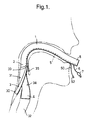
- the laryngeal mask assembly has a tubular shaft 1 of a bendable plastics material, such as PVC, which is bent to conform to the anatomy of the patient.
- the assembly has a laryngeal mask member 3 and an inflatable laryngeal cuff 4, which will be described in detail later.
- the interior of the laryngeal cuff 4 communicates with an inflation lumen 5 extending along the length of the shaft 1, within its wall, which connects to a small bore inflation line 6 terminated by a combined inflation indicator and connector 7.
- the machine end 8 of the assembly projects a short distance from the patient's mouth.
- the laryngeal mask member may be of the conventional inflatable kind, such as described in GB 2205499, in which case it would communicate with a separate inflation line.
- the mask 3 is non-inflatable and in the form of a thin, flexible, resilient skirt 30 of elliptical shape attached to the outside of the shaft 1 at its patient end 2.
- the peripheral shape of the mask 3 is chosen so that it conforms to and seals with tissue in the region of the hypopharynx 31, so as to form a seal around the circumference of the opening 33 of the laryngeal inlet 34.
- the patient end 2 of the shaft 1 supports the laryngeal cuff 4, which projects axially beyond the patient end of the shaft.
- the cuff 4 is of cylindrical shape with an inner wall 40 and an outer wall 41.
- the inner wall 40 carries several annular reinforcing members 42 spaced from one another along a rear portion 43 of the cuff, which act to keep open a central passage 44 through the rear part of the cuff.
- the cuff 4 Towards its forward end, the cuff 4 has two curved plates 45 and 46 diametrically opposite one another, which serve to stiffen the forward portion of the cuff.
- the forward end of the cuff 4 is formed, as shown in Figure 2A, so that its resilience urges a flap region 47, extending around approximately half the circumference of the cuff, towards the opposite side of the cuff so that the forward end of the cuff lies approximately along the plane containing the forward surface of the skirt 30. It can be seen that, in this state, the opening to the forward end of the shaft 1 is closed.
- the assembly also includes a pull cord 50 extending within the cuff 4 and attached at its forward end to the flap region 47.
- the cord 50 extends along the length of the assembly, through a passage 51 extending through the shaft 1.
- the rear end 52 of the cord 50 extends from the machine end of the assembly, as shown in Figure 1.
- the cord 50 is arranged so that, when it is pulled, it pulls the flap region 47 away from the opposite side of the cuff, as shown in Figure 2B. In this position, the length of the cuff 4 is such that it just projects beyond the forward, patient end of the mask 3.
- the mask assembly is introduced in any of the conventional ways used with laryngeal masks, so that the mask 3 is located to extend around the opening 33 of the laryngeal inlet 34.
- the assembly is introduced with the cuff 4 in the state shown in Figure 2A, that is, with the flap region 47 covering the opening to the cuff. This prevents the epiglottis 35 entering the patient end of the assembly during insertion.
- the clinician then pulls the cord 50 so that the flap 47 swings down to the right, opening the passage through the assembly and displacing the epiglottis to one side, if this should be folded down across the patient end of the mask 3.
- This also causes the patient end 2 of the shaft and the laryngeal cuff 4 to project into the laryngeal inlet.
- the clinician then introduces a measured volume of air via the connector 7 into the cuff 4 so that it expands axially and radially into the laryngeal inlet 34.
- the cord 50 may be clipped in some way at its machine end, so that flap 47 remains open, or the inflation of the cuff with the introduced air may be sufficient by itself to keep the flap open.
- the cuff 4 When the cuff 4 is inflated, it extends both axially and radially outwards to a position shown in Figure 2C. In this position, the cuff 4 extends into the laryngeal inlet 34 but does not extend within the larynx 32 itself. The radial expansion of the cuff causes it to seal with tissue in the laryngeal inlet.
- the assembly of the present invention can provide an improved seal compared with conventional laryngeal masks and has the advantage of ensuring that the epiglottis does not present any obstruction.
- the laryngeal cuff need not be expanded by positive air pressure but could be filled with a resilient material, such as a foam, and be reduced in volume for introduction or removal by a negative pressure, or some form of mechanical arrangement, such as pull cords.
- the mask need not seal around the laryngeal inlet but could seal in the pharyngeal region.
- the assembly has a non-inflatable cuff that projects within the laryngeal inlet 34 but does not make a complete seal with it.
- a non-inflatable cuff that projects within the laryngeal inlet 34 but does not make a complete seal with it.
- FIGs 3A to 3D Such an assembly is shown in Figures 3A to 3D.
- the assembly has a mask 3' of the same kind as shown in Figures 1 and 2 but, in place of the inflatable cuff 4 it has a cuff 4' formed of a resilient material, which, in its natural state, as shown in Figures 3C and 3D, has the shape of a flat funnel.
- the cuff 4' is divided by two recesses 60 and 61 into two lateral portions 62 and 63.
- one of the lateral portions 63 is inverted into the other 62, as shown in Figure 3A, so that the patient end of the cuff is closed and of semi-cylindrical shape. In this position, the cuff 4' does not project beyond the mask 3'.
- Two pull cords 64 and 65 are attached to the inverted portion 63 of the cuff 4' so that, once it is in position in the patient, the cords can be pulled, to open out the cuff to its natural shape shown in Figures 3B to 3D. This again causes the epiglottis 35 to be deflected out of the way, should it be located across the end of the mask 3'.
- the natural resilience of the cuff 4' urges the two portions 62 and 63 against opposite sides of the laryngeal inlet.
Abstract
Description
- Figure 1
- is a side elevation view of the laryngeal mask assembly in use;
- Figure 2A
- is an enlarged sectional side elevation view of the patient end of the mask assembly showing the laryngeal cuff before introduction;
- Figures 2B and 2C
- are enlarged sectional side elevation view of the patient end of the mask assembly showing the laryngeal cuff in an intermediate and expanded state respectively; and
- Figures 3A
- is a perspective view of the patient end of an alternative assembly before introduction;
- Figure 3B.
- is a sectional side elevation view of the assembly of Figure 3A before introduction;
- Figure 3C
- is a sectional side elevation view of the assembly as expanded after introduction; and
- Figure 3D
- is a perspective view of the patient end of the assembly as expanded after introduction.
Claims (8)
- A laryngeal mask assembly comprising a tubular shaft (1) having a mask portion (3) towards its patient end (2), the mask portion being adapted to seal with tissue in the region of the hypopharynx (31), characterised in that the assembly additionally includes an expansible tubular cuff member (4, 4') extending substantially axially of the tubular shaft (1) beyond the mask portion (3) into the laryngeal inlet (34).
- A laryngeal mask assembly according to Claim 1, characterised in that the cuff member (4) includes a deflectable member (47) at its patient end that, in one position, prevents entry of the epiglottis into the opening at the patient end of the assembly and, in another position, deflects the epiglottis away from the opening at the patient end of the assembly.
- A laryngeal mask assembly according to Claim 2, characterised in that the assembly includes a pull cord (50) attached with the deflectable member (47) by which the deflectable member can be moved from the one position to the other position.
- A laryngeal mask assembly according to any one of the preceding claims, characterised in that the mask portion is a non-inflatable resilient skirt (3).
- A laryngeal mask assembly according to any one of the preceding claims, characterised in that the cuff member (4) is inflatable.
- A laryngeal mask assembly according to any one of Claims 1 to 4, characterised in that the cuff member is a resilient funnel-shape member (4').
- A laryngeal mask assembly according to any one of the preceding claims, characterised in that the cuff member (4) includes at least one annular reinforcing member (42) arranged to keep open a central passage through a part of the cuff member.
- A laryngeal mask assembly according to Claim 7, characterised in that the cuff member (4) includes a plurality of the annular reinforcement members (42).
Applications Claiming Priority (2)
| Application Number | Priority Date | Filing Date | Title |
|---|---|---|---|
| GBGB9709297.7A GB9709297D0 (en) | 1997-05-03 | 1997-05-03 | Laryngeal mask assemblies |
| GB9709297 | 1997-05-03 |
Publications (2)
| Publication Number | Publication Date |
|---|---|
| EP0880975A2 true EP0880975A2 (en) | 1998-12-02 |
| EP0880975A3 EP0880975A3 (en) | 1999-01-07 |
Family
ID=10811961
Family Applications (1)
| Application Number | Title | Priority Date | Filing Date |
|---|---|---|---|
| EP98303346A Withdrawn EP0880975A3 (en) | 1997-05-03 | 1998-04-29 | Laryngeal mask assemblies |
Country Status (6)
| Country | Link |
|---|---|
| US (1) | US6095144A (en) |
| EP (1) | EP0880975A3 (en) |
| JP (1) | JPH10314308A (en) |
| AU (1) | AU6371498A (en) |
| GB (1) | GB9709297D0 (en) |
| ZA (1) | ZA983674B (en) |
Cited By (2)
| Publication number | Priority date | Publication date | Assignee | Title |
|---|---|---|---|---|
| FR2799377A1 (en) * | 1999-10-06 | 2001-04-13 | Smiths Industries Plc | LARYNGIAN MASK ASSEMBLY |
| GB2371990A (en) * | 2000-12-22 | 2002-08-14 | Smiths Group Plc | Laryngeal Mask Assemblies |
Families Citing this family (59)
| Publication number | Priority date | Publication date | Assignee | Title |
|---|---|---|---|---|
| NL1004640C2 (en) * | 1996-11-28 | 1998-06-05 | Ideamed N V | Ventilation equipment. |
| US6079409A (en) * | 1997-07-25 | 2000-06-27 | Brain; Archibald Ian Jeremy | Intubating laryngeal mask |
| US7331346B2 (en) * | 1997-12-24 | 2008-02-19 | Indian Ocean Medical, Inc. | Monitoring and control for a laryngeal mask airway device |
| GB9727367D0 (en) * | 1997-12-24 | 1998-02-25 | Brain Archibald Ian Jeremy | Improvements in laryngeal mask airway devices |
| GB9817537D0 (en) * | 1998-08-13 | 1998-10-07 | Brain Archibald Ian Jeremy | A laryngear mask airway with mutually independant laterally-placed ultra-flexible eastric access/discharge and airway tubes |
| GB2328879B (en) * | 1998-09-19 | 1999-07-21 | Amer Shaikh | An intubation device |
| GB9821771D0 (en) * | 1998-10-06 | 1998-12-02 | Brain Archibald Ian Jeremy | Improvements relating to laryngeal mask airway devices |
| US6705318B1 (en) * | 1999-04-09 | 2004-03-16 | Archibald I. J. Brain | Disposable LMA |
| US6631720B1 (en) * | 1999-10-07 | 2003-10-14 | Archibald I. J. Brain | Laryngeal mask with large-bore gastric drainage |
| GB0103815D0 (en) * | 2001-02-16 | 2001-04-04 | Smiths Group Plc | Laryngeal mask assemblies |
| GB0103813D0 (en) * | 2001-02-16 | 2001-04-04 | Smiths Group Plc | Laryngeal mask assemblies |
| US7159589B2 (en) | 2001-08-23 | 2007-01-09 | Indian Ocean Medical Inc. | Disposable laryngeal mask airway device |
| US7040322B2 (en) * | 2001-11-08 | 2006-05-09 | Fortuna Anibal De Oliveira | Combination artificial airway device and esophageal obturator |
| US7762261B1 (en) * | 2001-11-08 | 2010-07-27 | Fortuna Anibal De Oliveira | Combination artificial airway device and esophageal obturator |
| US6705322B2 (en) * | 2002-03-11 | 2004-03-16 | Ti-Li Chang | Laryngeal mask airway |
| US7040312B2 (en) * | 2002-05-16 | 2006-05-09 | Engineered Medical Systems, Inc. | Perilaryngeal oral airway with flexible tip guide |
| GB0218868D0 (en) | 2002-08-14 | 2002-09-25 | Nasir Muhammed A | Improved airway management device |
| US6792948B2 (en) * | 2003-01-22 | 2004-09-21 | Archibald I. J. Brain | Laryngeal mask airway device with airway tube having flattened outer circumference and elliptical inner airway passage |
| TWM240225U (en) * | 2003-04-10 | 2004-08-11 | Di-Li Jang | Improved throat mask |
| GB2404863B (en) * | 2003-08-14 | 2008-05-14 | Muhammed Aslam Nasir | Improved airway device |
| US7134431B2 (en) * | 2003-09-08 | 2006-11-14 | Indian Ocean Medical Inc. | Laryngeal mask airway device with position controlling tab |
| US7128071B2 (en) * | 2003-09-10 | 2006-10-31 | Indian Ocean Medical Inc. | Intubating laryngeal mask airway device with fiber optic assembly |
| US7096868B2 (en) * | 2004-03-09 | 2006-08-29 | Nellcor Puritan Bennett Incorporated | Laryngeal airway device |
| GB0510951D0 (en) | 2005-05-27 | 2005-07-06 | Laryngeal Mask Company The Ltd | Laryngeal mask airway device |
| US20070058123A1 (en) * | 2005-09-15 | 2007-03-15 | Samsung Electronics Co., Ltd. | Liquid crystal display |
| US7654264B2 (en) | 2006-07-18 | 2010-02-02 | Nellcor Puritan Bennett Llc | Medical tube including an inflatable cuff having a notched collar |
| US7900632B2 (en) * | 2006-08-18 | 2011-03-08 | Cookgas, L.L.C. | Laryngeal mask with esophageal blocker and bite block |
| GB0620862D0 (en) * | 2006-10-20 | 2006-11-29 | Smiths Group Plc | Laryngeal mask assemblies |
| US20080257356A1 (en) * | 2007-04-23 | 2008-10-23 | The Penn State Research Foundation | Control tip for supraglottic airway device |
| GB0719054D0 (en) * | 2007-09-29 | 2007-11-07 | Nasir Muhammed A | Airway device |
| GB0810169D0 (en) * | 2008-06-04 | 2008-07-09 | Cosmeplast Ets | Improvements relating to respiratory interface devices |
| GB0903654D0 (en) | 2009-03-03 | 2009-04-15 | Laryngeal Mask Company The Ltd | Artificial airway device |
| NZ596124A (en) | 2009-04-08 | 2012-12-21 | Meenakshi Baska | Laryngeal mask for maintaining an airway in a patient with means to cause elastic deformation of the device to facilitate insertion |
| AU2010269117B2 (en) | 2009-07-06 | 2014-07-10 | Teleflex Life Sciences Llc | Artificial airway |
| USD665495S1 (en) | 2009-07-14 | 2012-08-14 | Muhammed Aslam Nasir | Medical device |
| AU2010282221B2 (en) | 2009-08-13 | 2015-02-05 | Teleflex Life Sciences Llc | Pressure indicator |
| GB201010647D0 (en) | 2010-06-24 | 2010-08-11 | Docsinnovent Ltd | Stopper device |
| GB201016562D0 (en) | 2010-10-01 | 2010-11-17 | Laryngeal Mask Company The Ltd | Artificial airway device |
| JP5922135B2 (en) | 2010-10-15 | 2016-05-24 | ザ ラリンジアル マスク カンパニー リミテッド | Artificial airway device |
| JP6242687B2 (en) | 2011-02-02 | 2017-12-06 | ウメダス、リミテッドUmedaes Limited | Improved artificial airway |
| GB2489258A (en) * | 2011-03-22 | 2012-09-26 | Donald Munro Miller | Supra-laryngeal device which seals against the pharynx |
| USD693920S1 (en) | 2011-06-08 | 2013-11-19 | Intersurgical Ag | Airway device |
| USD665254S1 (en) | 2011-06-08 | 2012-08-14 | Intersurgical Ag | Airway device packaging |
| USD688787S1 (en) | 2011-06-08 | 2013-08-27 | Intersurgical Ag | Airway device cap and strap holder |
| USD712244S1 (en) | 2011-09-23 | 2014-09-02 | Intersurgical Ag | Medical device package |
| GB201120628D0 (en) | 2011-11-30 | 2012-01-11 | Laryngeal Mask Company The Ltd | Endoscopy device |
| USD761952S1 (en) | 2012-07-27 | 2016-07-19 | Docsinnovent Limited | Airway device |
| GB201201438D0 (en) | 2012-01-27 | 2012-03-14 | Docsinnovent Ltd | Improved stopper device |
| PL2854919T3 (en) * | 2012-06-04 | 2019-02-28 | Singularity Ag | Laryngeal mask |
| EP2903673B1 (en) * | 2012-10-08 | 2017-09-20 | The Cleveland Clinic Foundation | Reversible airway device |
| US10675425B2 (en) | 2013-10-08 | 2020-06-09 | The Cleveland Clinic Foundation | Reversible airway device and related method for ventilating a subject |
| GB2555360B (en) | 2013-12-17 | 2018-10-10 | Intersurgical Ag | Intubating Airway Device |
| USD842456S1 (en) | 2015-12-15 | 2019-03-05 | Intersurgical Ag | Airway device |
| WO2018013795A1 (en) * | 2016-07-14 | 2018-01-18 | University Of Virginia Patent Foundation | Multiple beak endotracheal device and related methods thereof |
| US10213567B1 (en) * | 2017-11-08 | 2019-02-26 | Shan Theventhiran | Easily removable intubating LMA |
| GB201720733D0 (en) | 2017-12-13 | 2018-01-24 | Ashkal Development Ltd | Airway device |
| US11638797B2 (en) * | 2019-03-21 | 2023-05-02 | Airway Management Solutions, Llc | Apparatus for enabling blind endotracheal tube or guide wire insertion into the trachea |
| US20210162154A1 (en) * | 2019-11-30 | 2021-06-03 | Yang Sun | A Supraglottic Airway Device for intermittent Positive Pressure Ventilation |
| CN116763412B (en) * | 2023-07-07 | 2024-02-27 | 青岛市妇女儿童医院(青岛市妇幼保健院、青岛市残疾儿童医疗康复中心、青岛市新生儿疾病筛查中心) | Digestive tract foreign body extraction device |
Citations (2)
| Publication number | Priority date | Publication date | Assignee | Title |
|---|---|---|---|---|
| US4995388A (en) * | 1989-03-22 | 1991-02-26 | Brain Archibald I | Artificial airway device |
| WO1997012641A1 (en) * | 1995-10-03 | 1997-04-10 | Archibald Ian Jeremy Brain | Laryngeal mask airway incorporating an epiglottic elevating mechanism |
Family Cites Families (6)
| Publication number | Priority date | Publication date | Assignee | Title |
|---|---|---|---|---|
| US4329983A (en) * | 1980-05-09 | 1982-05-18 | Fletcher Thomas S | Guide device for endotracheal tubes |
| GB2205499B (en) * | 1987-06-05 | 1991-01-16 | Archibald Ian Jeremy Brain | Artificial airway device |
| GB9102821D0 (en) * | 1991-02-11 | 1991-03-27 | Brain Archibald Ian Jeremy | An intubating laryngeal mask airway |
| US5297547A (en) * | 1992-07-30 | 1994-03-29 | Brain Archibald Ian Jeremy | Laryngeal mask construction |
| GB2317342B (en) * | 1996-09-18 | 2000-03-29 | Smiths Industries Plc | Laryngeal mask assemblies |
| US5967859A (en) * | 1997-12-10 | 1999-10-19 | Molex Incorporated | Electrical connector assembly with terminal retainer system |
-
1997
- 1997-05-03 GB GBGB9709297.7A patent/GB9709297D0/en active Pending
-
1998
- 1998-04-29 EP EP98303346A patent/EP0880975A3/en not_active Withdrawn
- 1998-04-29 AU AU63714/98A patent/AU6371498A/en not_active Abandoned
- 1998-04-30 US US09/069,938 patent/US6095144A/en not_active Expired - Fee Related
- 1998-04-30 ZA ZA983674A patent/ZA983674B/en unknown
- 1998-05-01 JP JP10122099A patent/JPH10314308A/en active Pending
Patent Citations (2)
| Publication number | Priority date | Publication date | Assignee | Title |
|---|---|---|---|---|
| US4995388A (en) * | 1989-03-22 | 1991-02-26 | Brain Archibald I | Artificial airway device |
| WO1997012641A1 (en) * | 1995-10-03 | 1997-04-10 | Archibald Ian Jeremy Brain | Laryngeal mask airway incorporating an epiglottic elevating mechanism |
Cited By (3)
| Publication number | Priority date | Publication date | Assignee | Title |
|---|---|---|---|---|
| FR2799377A1 (en) * | 1999-10-06 | 2001-04-13 | Smiths Industries Plc | LARYNGIAN MASK ASSEMBLY |
| GB2371990A (en) * | 2000-12-22 | 2002-08-14 | Smiths Group Plc | Laryngeal Mask Assemblies |
| GB2371990B (en) * | 2000-12-22 | 2004-06-16 | Smiths Group Plc | Laryngeal mask assemblies |
Also Published As
| Publication number | Publication date |
|---|---|
| AU6371498A (en) | 1998-11-05 |
| GB9709297D0 (en) | 1997-06-25 |
| ZA983674B (en) | 1998-11-24 |
| JPH10314308A (en) | 1998-12-02 |
| US6095144A (en) | 2000-08-01 |
| EP0880975A3 (en) | 1999-01-07 |
Similar Documents
| Publication | Publication Date | Title |
|---|---|---|
| US6095144A (en) | Laryngeal mask assemblies | |
| AU733952B2 (en) | Laryngeal mask assemblies | |
| EP0834331B1 (en) | Laryngeal mask airways and their manufacture | |
| JP3964531B2 (en) | Laryngeal mask assembly | |
| AU732963B2 (en) | Laryngeal mask assemblies | |
| EP0794807B1 (en) | Artificial airway device | |
| AU736181B2 (en) | Laryngeal mask assemblies | |
| EP0651664B1 (en) | Laryngeal mask airway with concentric drainage of oesophagus discharge | |
| US8449713B2 (en) | Gastro-laryngeal mask | |
| JP3565866B2 (en) | Artificial respiration | |
| EP0489507A1 (en) | Endotracheal tube | |
| US6761170B2 (en) | Laryngeal mask assemblies | |
| GB2324737A (en) | Laryngeal mask assembly | |
| GB2317830A (en) | Laryngeal mask assembly | |
| GB2323289A (en) | Laryngeal mask assembly | |
| EP1005877A2 (en) | Cuffed tubes | |
| AU772557B2 (en) | Laryngeal mask assemblies | |
| EP1242137B1 (en) | Artificial airway device and method of its use | |
| US20080092903A1 (en) | Laryngeal mask assemblies | |
| CA2100998C (en) | Laryngeal mask airway with concentric drainage of oesophagus discharge | |
| CA2412474A1 (en) | Artificial airway device and method of its use |
Legal Events
| Date | Code | Title | Description |
|---|---|---|---|
| PUAI | Public reference made under article 153(3) epc to a published international application that has entered the european phase |
Free format text: ORIGINAL CODE: 0009012 |
|
| PUAL | Search report despatched |
Free format text: ORIGINAL CODE: 0009013 |
|
| AK | Designated contracting states |
Kind code of ref document: A2 Designated state(s): DE DK ES FR GB IE IT NL SE |
|
| AX | Request for extension of the european patent |
Free format text: AL;LT;LV;MK;RO;SI |
|
| AK | Designated contracting states |
Kind code of ref document: A3 Designated state(s): AT BE CH CY DE DK ES FI FR GB GR IE IT LI LU MC NL PT SE |
|
| AX | Request for extension of the european patent |
Free format text: AL;LT;LV;MK;RO;SI |
|
| RHK1 | Main classification (correction) |
Ipc: A61M 16/04 |
|
| 17P | Request for examination filed |
Effective date: 19990507 |
|
| AKX | Designation fees paid | ||
| RBV | Designated contracting states (corrected) |
Designated state(s): DE DK ES FR GB IE IT NL SE |
|
| STAA | Information on the status of an ep patent application or granted ep patent |
Free format text: STATUS: THE APPLICATION IS DEEMED TO BE WITHDRAWN |
|
| 18D | Application deemed to be withdrawn |
Effective date: 20011101 |