EP0882436A1 - Transport and process device for two-component material - Google Patents
Transport and process device for two-component material Download PDFInfo
- Publication number
- EP0882436A1 EP0882436A1 EP97810352A EP97810352A EP0882436A1 EP 0882436 A1 EP0882436 A1 EP 0882436A1 EP 97810352 A EP97810352 A EP 97810352A EP 97810352 A EP97810352 A EP 97810352A EP 0882436 A1 EP0882436 A1 EP 0882436A1
- Authority
- EP
- European Patent Office
- Prior art keywords
- container
- liquid component
- piston
- transport
- mixing
- Prior art date
- Legal status (The legal status is an assumption and is not a legal conclusion. Google has not performed a legal analysis and makes no representation as to the accuracy of the status listed.)
- Granted
Links
Images


Classifications
-
- A—HUMAN NECESSITIES
- A61—MEDICAL OR VETERINARY SCIENCE; HYGIENE
- A61B—DIAGNOSIS; SURGERY; IDENTIFICATION
- A61B17/00—Surgical instruments, devices or methods, e.g. tourniquets
- A61B17/56—Surgical instruments or methods for treatment of bones or joints; Devices specially adapted therefor
- A61B17/58—Surgical instruments or methods for treatment of bones or joints; Devices specially adapted therefor for osteosynthesis, e.g. bone plates, screws, setting implements or the like
- A61B17/88—Osteosynthesis instruments; Methods or means for implanting or extracting internal or external fixation devices
- A61B17/8802—Equipment for handling bone cement or other fluid fillers
- A61B17/8805—Equipment for handling bone cement or other fluid fillers for introducing fluid filler into bone or extracting it
- A61B17/8827—Equipment for handling bone cement or other fluid fillers for introducing fluid filler into bone or extracting it with filtering, degassing, venting or pressure relief means
-
- B—PERFORMING OPERATIONS; TRANSPORTING
- B01—PHYSICAL OR CHEMICAL PROCESSES OR APPARATUS IN GENERAL
- B01F—MIXING, e.g. DISSOLVING, EMULSIFYING OR DISPERSING
- B01F31/00—Mixers with shaking, oscillating, or vibrating mechanisms
- B01F31/40—Mixers with shaking, oscillating, or vibrating mechanisms with an axially oscillating rotary stirrer
-
- B—PERFORMING OPERATIONS; TRANSPORTING
- B01—PHYSICAL OR CHEMICAL PROCESSES OR APPARATUS IN GENERAL
- B01F—MIXING, e.g. DISSOLVING, EMULSIFYING OR DISPERSING
- B01F33/00—Other mixers; Mixing plants; Combinations of mixers
- B01F33/50—Movable or transportable mixing devices or plants
- B01F33/501—Movable mixing devices, i.e. readily shifted or displaced from one place to another, e.g. portable during use
- B01F33/5011—Movable mixing devices, i.e. readily shifted or displaced from one place to another, e.g. portable during use portable during use, e.g. hand-held
- B01F33/50112—Movable mixing devices, i.e. readily shifted or displaced from one place to another, e.g. portable during use portable during use, e.g. hand-held of the syringe or cartridge type
-
- B—PERFORMING OPERATIONS; TRANSPORTING
- B01—PHYSICAL OR CHEMICAL PROCESSES OR APPARATUS IN GENERAL
- B01F—MIXING, e.g. DISSOLVING, EMULSIFYING OR DISPERSING
- B01F35/00—Accessories for mixers; Auxiliary operations or auxiliary devices; Parts or details of general application
- B01F35/30—Driving arrangements; Transmissions; Couplings; Brakes
- B01F35/32—Driving arrangements
- B01F35/32005—Type of drive
- B01F35/3202—Hand driven
-
- B—PERFORMING OPERATIONS; TRANSPORTING
- B01—PHYSICAL OR CHEMICAL PROCESSES OR APPARATUS IN GENERAL
- B01F—MIXING, e.g. DISSOLVING, EMULSIFYING OR DISPERSING
- B01F35/00—Accessories for mixers; Auxiliary operations or auxiliary devices; Parts or details of general application
- B01F35/71—Feed mechanisms
- B01F35/713—Feed mechanisms comprising breaking packages or parts thereof, e.g. piercing or opening sealing elements between compartments or cartridges
- B01F35/7131—Breaking or perforating packages, containers or vials
-
- B—PERFORMING OPERATIONS; TRANSPORTING
- B01—PHYSICAL OR CHEMICAL PROCESSES OR APPARATUS IN GENERAL
- B01F—MIXING, e.g. DISSOLVING, EMULSIFYING OR DISPERSING
- B01F35/00—Accessories for mixers; Auxiliary operations or auxiliary devices; Parts or details of general application
- B01F35/71—Feed mechanisms
- B01F35/716—Feed mechanisms characterised by the relative arrangement of the containers for feeding or mixing the components
- B01F35/7162—A container being placed inside the other before contacting the contents
-
- B—PERFORMING OPERATIONS; TRANSPORTING
- B01—PHYSICAL OR CHEMICAL PROCESSES OR APPARATUS IN GENERAL
- B01F—MIXING, e.g. DISSOLVING, EMULSIFYING OR DISPERSING
- B01F35/00—Accessories for mixers; Auxiliary operations or auxiliary devices; Parts or details of general application
- B01F35/75—Discharge mechanisms
- B01F35/754—Discharge mechanisms characterised by the means for discharging the components from the mixer
- B01F35/75425—Discharge mechanisms characterised by the means for discharging the components from the mixer using pistons or plungers
- B01F35/754251—Discharge mechanisms characterised by the means for discharging the components from the mixer using pistons or plungers reciprocating in the mixing receptacle
-
- A—HUMAN NECESSITIES
- A61—MEDICAL OR VETERINARY SCIENCE; HYGIENE
- A61F—FILTERS IMPLANTABLE INTO BLOOD VESSELS; PROSTHESES; DEVICES PROVIDING PATENCY TO, OR PREVENTING COLLAPSING OF, TUBULAR STRUCTURES OF THE BODY, e.g. STENTS; ORTHOPAEDIC, NURSING OR CONTRACEPTIVE DEVICES; FOMENTATION; TREATMENT OR PROTECTION OF EYES OR EARS; BANDAGES, DRESSINGS OR ABSORBENT PADS; FIRST-AID KITS
- A61F2250/00—Special features of prostheses classified in groups A61F2/00 - A61F2/26 or A61F2/82 or A61F9/00 or A61F11/00 or subgroups thereof
- A61F2250/0058—Additional features; Implant or prostheses properties not otherwise provided for
- A61F2250/0071—Additional features; Implant or prostheses properties not otherwise provided for breakable or frangible
-
- B—PERFORMING OPERATIONS; TRANSPORTING
- B01—PHYSICAL OR CHEMICAL PROCESSES OR APPARATUS IN GENERAL
- B01F—MIXING, e.g. DISSOLVING, EMULSIFYING OR DISPERSING
- B01F2101/00—Mixing characterised by the nature of the mixed materials or by the application field
- B01F2101/20—Mixing of ingredients for bone cement
-
- B—PERFORMING OPERATIONS; TRANSPORTING
- B01—PHYSICAL OR CHEMICAL PROCESSES OR APPARATUS IN GENERAL
- B01F—MIXING, e.g. DISSOLVING, EMULSIFYING OR DISPERSING
- B01F33/00—Other mixers; Mixing plants; Combinations of mixers
- B01F33/50—Movable or transportable mixing devices or plants
- B01F33/501—Movable mixing devices, i.e. readily shifted or displaced from one place to another, e.g. portable during use
- B01F33/5011—Movable mixing devices, i.e. readily shifted or displaced from one place to another, e.g. portable during use portable during use, e.g. hand-held
Definitions
- the invention relates to a transport and Processing device for two-component material, especially for bone cement, with a Liquid component and with a powder component a transport space separated by a membrane in a closable container, which is open an ejection piston on one side and on the other an opening for ejection on the opposite side of mixed two-component material, and which includes a perforated mixing flask.
- Such a device is in EP-A-0 692 229 shown.
- a discharge piston and a Mixing piston is arranged between a discharge piston and a Mixing piston that the powdery area from the area of the liquid component separates.
- the mixing cylinder consists of two separate ones Transport cylinders together, which have a Quick coupling can be assembled. This has the Disadvantage that mixing pistons, separating pistons and Ejection piston during its actuation via a Separation point between the transport cylinders run which is a discontinuity.
- the object of the present invention is a safe and functional transport and To create processing device.
- This task is carried out with the marks of the independent Claim 1 solved in that the transport space for the Liquid component ring-shaped with a medium one Breakthrough and executed with a membrane that mixed two-component material through the middle Breakthrough and the opening is ejectable and that by a relative movement between the transport space Liquid component and one enclosed in the container solid body that is destructible to a membrane Flow of the liquid component in the transport space of the To effect powder component.
- An advantage of this device is that it can be used without rubber-like soft seals in the form of O-rings or Lips is executable. This allows the device except for a membrane made of molded plastic parts to manufacture. Furthermore, no collapsed Transport container when the mixture is ejected through the Ejection piston to be moved.
- Another advantage of this device is that pre-assembled plastic injection parts to a filling plant are available and that with the filling a final Assembly, welding and where necessary Sterilization is possible. Regardless of transportation and Storage arrive under controlled conditions filled quantities with the operational device the immediate place of work. For mixing and ejecting of the two components, the device can be used externally be operated. The interior is up to the touch lockable.
- the membrane By forming the membrane as an annular film, can the transport space of the liquid component in one simple injection mold and is one Attack power to destroy the membrane anywhere on the Cross section of the transport space effective.
- One from the outside closable filling opening on the transport space of the Liquid component allows liquid component and Powder component in the same vertical position To fill the container.
- a displacement body which in penetrates the transport space of the liquid component the advantage that the liquid component inevitably and is ejected regardless of gravity.
- a displacer can be provided with a cutting edge and so the membrane with the beginning of the relative movement between the displacer and the transport space of the Destroy liquid.
- An execution of the transport space of the liquid component as an annular space it also allows the transport space in to integrate a container lid that is opposite the Container is axially movable to the membrane on a to destroy the fixed cutting edge in the container and around the Liquid component under gravity in the underlying transport space of the powder component to flow.
- a lead ring is an advantage over which the liquid component flows off and on Drag ring, which is the first axial lowering of the Container lid latched with this and when lifting the Container lid releases a drain cross section. At the container lid is lowered again Drain cross-section closed again during the then mixing and ejecting the two Components to prevent bone cement in the Transport space of the liquid component arrives.
- One of externally controllable axial movement can, for example, by a container lid with one to the container helically guided rotary movement are generated.
- the figures show transport and Processing devices for two-component material, especially for bone cement, with a Liquid component and with a powder component, the a transport space separated by a membrane in a closable container, which is open an ejection piston on one side and on the other an opening for ejection on the opposite side of mixed two-component material.
- annular design of the transport space Liquid component with a medium breakthrough can mixed two-component material through the breakthrough be expelled.
- By a relative movement between the transport space of the liquid component and one in Container enclosed solid body becomes the membrane destroyed to allow the liquid component to flow into the To effect transport space of the powder component and that Allow mixing with a mixing flask.
- the device would be usable for Mix the two components.
- the device With bone cement the device for transport and storage in a film welded in and with ⁇ -rays or gas, e.g. Sterilized ethylene oxide or formaldehyde.
- gas e.g. Sterilized ethylene oxide or formaldehyde.
- the parts of the Device are injection molded plastic executed and transparent to the filling process and to be able to monitor the mixing later.
- the Sterilization is done either before filling ⁇ -radiation, or afterwards with gas, so that the liquid does not take damage from ⁇ -rays.
- Sealing plug 14 and its handle can be from unscrew the piston rod 10. Because the most parts of the main axis 33 largely are carried out rotationally symmetrical cheap injection molds.
- Container 6 and Ejection pistons 8 are also preassembled.
- Transport space 4 for the liquid component 1 is a separate container that contains the liquid component 1 filled and closed with a film 3 and is welded.
- To fill the device Mixing piston 11 and piston rod 10 in container 6 used.
- the lid 7 with the integrated displacement body 12 is placed and closes the container 6 with the screw connection 23.
- the closure 14 which is a handle and has a protuberance up to the mixing piston 11 with which tubular piston rod 10 via a thread at Handle connected.
- the protuberance 15 prevents in the subsequent mixing, dead spaces with unequal Distribution of components 1, 2 arise.
- FIGs. 5, 6 and 7a to 7i Another construction is in Figs. 5, 6 and 7a to 7i.
- the device consists (Fig. 5, 6) of a to a longitudinal axis 33 concentric arrangement with a Container 6, which has an opening for has a hub from the ejection piston 8 and via a Bayonet lock 31 with a feed device 27 (Fig. 7i) can be connected.
- On its top is the Container 6 via a screw connection 23 with a lid 7 closed, which has an opening 9, of the a suction opening 21 branches off with filter 26.
- the lid 7 is also a transport space 4 for the Liquid component 1 executed.
- At its bottom is he with a membrane 3 in the form of an annular film 16 closed. There is no one on its top centric fill opening 19 attached with a Plug 42 is closable.
- a displacer 12 is in a transport position with the container 6 a snap connection 20 connected and has one Outflow pipe 41, which through the opening 9 in the cover 7th is brought out.
- the outflow pipe 41 is with a The protuberance 15 can be closed.
- Outlets 37 attached, which are released when a mixing piston 11 the top position opposite reached the displacer 12 and the protuberance 15 pushes back.
- the outflow pipe 41 is a construction Part of a cover 24 that covers the hollow Displacer 12 closes.
- the mixing piston 11 is in its lower position with the ejection piston 8 a latch 40 can be connected, the ejection piston 8 in its lower position via a rotation lock 39 can absorb 6 torques to the container.
- Ejection piston 8 has a central hub Bore through a piece of the piston rod 10 for the Mixing piston 11 in the form of a sleeve with a thread is brought out.
- the actual piston rod 10 has a handle 32 and a stop 48. It is can be screwed to the mixing piston 11 via a thread.
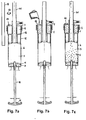
- the 7a shows the device in the preassembled state.
- the ejection piston 8 is inserted.
- the mixing piston 11 is in the lowest position with the ejection piston 8 latched and its piston rod 10 is inserted.
- Of the Displacer body 12 with outflow pipe 41 is connected to the Container 6 connected in the transport position.
- the cover 7 is screwed to the container 6.
- the filled container 6 with the Ausstülpung 15 closed can for example for Bone cement in this arrangement in a foil welded in and sterilized.
- the device is transportable and storable in this arrangement and at any time for mixing and discharging Two-component material 1, 2 ready for operation.
- Fig. 7h is a hose to the suction opening 21 Sucking off solvent vapors, where a Filter 26 penetration of solid or viscous Prevents particles.
- Fig. 7i a not shown Feed device 27 attached to the bayonet lock 31. This acts with a push rod 44 on the Ejection piston 8. As soon as the protuberance 15 is complete removed, the still liquid cement over a Mouth 43 are pressed out of the discharge pipe 41.
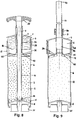
- FIG. 8 is an operational device shown.
- the container 6 is through on the bottom closed the ejection piston 8, on which the Mixing piston 11 rests.
- the mixing piston 11 is about a piston rod 10 actuates a releasable Has connection 45 to the mixing piston 11 and after is led out from the top of the container lid 7 and with completes a handle 32.
- the transport room 5 for the powder component 2 is upwards by a pressed-in discharge ring 35 and by a drag ring 36 completed.
- At the stationary discharge ring 35 are some, for example four, cutters 17 attached and a latch 40 for the mixing piston 11.
- the Drag ring 36 can only be overcome by overcoming one Clamping force can be moved in the axial direction. He blocks with its uppermost position in the cover 7 and can then only be moved with the lid.
- the lid 7 has a central opening 34 through which the Piston rod 10 can be inserted and pulled out. After this Mixing and pulling out the piston rod can Cement through this middle breakthrough 34 and the on it subsequent opening 9 are ejected.
- the lid 7 is an annular transport space 4 for the Running liquid component 1 and on its underside closed with a film 16.
- the lid is in radial direction in recesses in the form of a helix 38 stored and can move forward and backward by about 60 ° can be rotated relative to the container 6, one Stroke of about 6 mm.
- Fig. 9 the cement 18 is already mixed.
- the Piston rod 10 is by loosening the connection 45 has been pulled out and instead is a spout 41 with mouth 43 via a coupling 46 on cover 7 been scheduled.
- the lid 7 is in his lower position opposite the container 6 and secures the Drag ring 36.
- FIG. 10a The delivery state of the device is shown in FIG. 10a shown the bottling.
- the Ejection piston 8 used on the container 6 .
- the lid 7 is already sealed with a film 16 and with the inserted drag ring 36 in its upper position has been attached to the container 6 and has another opening 19 for filling. Sealing plug 42 and piston rod 10 with handle 32 become loose included.
- Fig. 10b the liquid component 1 is in its Transport space 4 filled.
- a filling probe is also here advantageous.
- the sealing film 16 may do not damage.
- 10c is the transport space 4 of the liquid component 1 already closed with the plug 42 and the Transport space 5 of the powder component 2 is filled.
- a submersible probe for filling is also an advantage here.
- Fig. 10d the piston rod 10 was filled into the Container 6 inserted from above and in its deepest Position over a collar with the container lid 7 connected.
- the mixer piston was off when driving downwards its latch 40 released and taken away.
- a detachable connection 45 was Piston rod 10 made. The device would now be for one Mix ready for use and can be stored in this form and be transported.
- 10j is an outflow pipe instead of the suction pipe 47 41 attached with a clutch 46.
- a feed device 27 On the bottom a feed device 27 has been attached to the container, the one with a push rod 44 the cement over a mouth 43 can eject at the outlet pipe 41.
Abstract
Description
Die Erfindung handelt von einer Transport- und Verarbeitungsvorrichtung für Zweikomponentenmaterial, insbesondere für Knochenzement, mit einer Flüssigkomponente und mit einer Pulverkomponente die durch eine Membran getrennt jeweils einen Transportraum in einem verschliessbaren Behälter einnehmen, welcher auf der einen Seite einen Ausstosskolben und auf der gegenüberliegenden Seite eine Oeffnung für das Ausstossen von gemischtem Zweikomponentenmaterial aufweist, und welcher einen perforierten Mischkolben einschliesst.The invention relates to a transport and Processing device for two-component material, especially for bone cement, with a Liquid component and with a powder component a transport space separated by a membrane in a closable container, which is open an ejection piston on one side and on the other an opening for ejection on the opposite side of mixed two-component material, and which includes a perforated mixing flask.
Eine solche Vorrichtung ist in der EP-A-0 692 229 gezeigt. Zwischen einem Austragskolben und einem Mischkolben ist ein Trennkolben angeordnet, der den pulverförmigen Bereich vom Bereich der Flüssigkomponente trennt. Der Mischzylinder setzt sich aus zwei getrennten Transportzylindern zusammen, die über eine Schnellkupplung zusammensetzbar sind. Dies hat den Nachteil, dass Mischkolben, Trennkolben und Ausstosskolben während ihrer Betätigung über eine Trennstelle zwischen den Transportzylindern laufen müssen, welche eine Unstetigkeit darstellt. Such a device is in EP-A-0 692 229 shown. Between a discharge piston and a Mixing piston is arranged a separating piston that the powdery area from the area of the liquid component separates. The mixing cylinder consists of two separate ones Transport cylinders together, which have a Quick coupling can be assembled. This has the Disadvantage that mixing pistons, separating pistons and Ejection piston during its actuation via a Separation point between the transport cylinders run which is a discontinuity.
Aufgabe der vorliegenden Erfindung ist es, eine sichere und funktionstüchtige Transport- und Verarbeitungsvorrichtung zu schaffen.The object of the present invention is a safe and functional transport and To create processing device.
Diese Aufgabe wird mit den Kennzeichen vom unabhängigen
Anspruch 1 dadurch gelöst, dass der Transportraum für die
Flüssigkomponente ringförmig mit einem mittleren
Durchbruch und mit einer Membran ausgeführt ist, dass
gemischtes Zweikomponentenmaterial durch den mittleren
Durchbruch und die Oeffnung ausstossbar ist und dass
durch eine Relativbewegung zwischen dem Transportraum der
Flüssigkomponente und eines im Behälter eingeschlossenen
festen Körpers, die Membran zerstörbar ist, um ein
Fliessen der Flüssigkomponente in den Transportraum der
Pulverkomponente zu bewirken.This task is carried out with the marks of the
Ein Vorteil dieser Vorrichtung ist, dass sie ohne gummiähnliche Weichdichtungen in Form von O-Ringen oder Lippen ausführbar ist. Dies gestattet es, die Vorrichtung bis auf eine Membran aus Kunststoffspritzteilen herzustellen. Im weiteren müssen keine kollabierten Transportbehälter beim Ausstossen der Mischung durch den Ausstosskolben mitbewegt werden.An advantage of this device is that it can be used without rubber-like soft seals in the form of O-rings or Lips is executable. This allows the device except for a membrane made of molded plastic parts to manufacture. Furthermore, no collapsed Transport container when the mixture is ejected through the Ejection piston to be moved.
Ein weiterer Vorteil dieser Vorrichtung ist, dass vormontierte Kunststoffspritzteile an ein Abfüllwerk lieferbar sind und dass mit dem Abfüllen eine endgültige Montage, ein Einschweissen und wo notwendig ein Sterilisieren möglich ist. Unabhängig von Transport und Lagerung gelangen unter kontrollierten Bedingungen abgefüllte Mengen mit der betriebsbereiten Vorrichtung an den unmittelbaren Arbeitsort. Zum Mischen und Ausstossen der beiden Komponenten kann die Vorrichtung äusserlich betätigt werden. Der Innenraum ist bis zum Anstossen verschliessbar. Another advantage of this device is that pre-assembled plastic injection parts to a filling plant are available and that with the filling a final Assembly, welding and where necessary Sterilization is possible. Regardless of transportation and Storage arrive under controlled conditions filled quantities with the operational device the immediate place of work. For mixing and ejecting of the two components, the device can be used externally be operated. The interior is up to the touch lockable.
Vorteilhafte Weiterbildungen der Erfindung sind in den
abhängigen Ansprüchen 2 bis 19 aufgeführt.Advantageous developments of the invention are in the
Durch ein Ausbilden der Membran als ringförmige Folie, kann der Transportraum der Flüssigkomponente in einem einfachen Spritzwerkzeug hergestellt werden und ist eine Angriffskraft zum Zerstören der Membran überall auf dem Querschnitt des Transportraumes wirksam. Eine von aussen verschliessbare Abfüllöffnung am Transportraum der Flüssigkomponente gestattet es, Flüssigkomponente und Pulverkomponente in der gleichen vertikalen Stellung des Behälters abzufüllen. Durch eine axiale Fixiermöglichkeit für den Mischkolben während Transport und Lagerung kann beim Mischen die Bewegung des Mischkolbens zum Zerstören der Membran genutzt werden. Ein Verdrängerkörper, der in den Transportraum der Flüssigkomponente eindringt, hat den Vorteil, dass die Flüssigkomponente zwangsläufig und unabhängig von der Schwerkraft ausgestossen wird. Der Verdrängerkörper kann mit einer Schneide versehen werden und so die Membran mit dem Beginn der Relativbewegung zwischen Verdrängerkörper und Transportraum der Flüssigkeit zerstören. Wenn sich Verdrängerkörper und Transportraum am Ende der Ausstossbewegung auch noch gegenseitig blockieren, wird dieser Vorgang irreversibel und es besteht keine Gefahr, dass unterschiedlich gemischte Produktteile in den Transportraum der Flüssigkomponente zurückgestossen werden. Mit einer hohlen Kolbenstange für den Mischkolben, die einen bis zum Kolben reichenden Verschluss aufweist, kann die Kolbenstange als Austrittsrohr genutzt werden, ohne dass Toträume mit ungleicher Mischung entstehen.By forming the membrane as an annular film, can the transport space of the liquid component in one simple injection mold and is one Attack power to destroy the membrane anywhere on the Cross section of the transport space effective. One from the outside closable filling opening on the transport space of the Liquid component allows liquid component and Powder component in the same vertical position To fill the container. With an axial fixation option for the mixing flask during transportation and storage when mixing the movement of the mixing piston to destroy the membrane can be used. A displacement body, which in penetrates the transport space of the liquid component the advantage that the liquid component inevitably and is ejected regardless of gravity. Of the A displacer can be provided with a cutting edge and so the membrane with the beginning of the relative movement between the displacer and the transport space of the Destroy liquid. If displacer and Transport space at the end of the ejection movement too blocking each other, this process becomes irreversible and there is no danger of being different mixed product parts in the transport space of the Liquid component are pushed back. With a hollow piston rod for the mixing piston, the one up to the piston reaching closure, the Piston rod can be used as an outlet tube without Dead spaces with an uneven mixture arise.
Eine Ausführung des Transportraumes der Flüssigkomponente als Ringraum gestattet es auch, den Transportraum in einen Behälterdeckel zu integrieren, der gegenüber dem Behälter axial beweglich ist, um die Membran an einer ortsfesten Schneide im Behälter zu zerstören und um die Flüssigkomponente unter Schwerkraft in den darunterliegenden Transportraum der Pulverkomponente fliessen zu lassen. Von Vorteil ist dabei ein Ableitring, über den die Flüssigkomponente abfliesst und ein Schleppring, der sich beim ersten axialen Absenken des Behälterdeckels mit diesem verklinkt und beim Anheben des Behälterdeckels einen Abflussquerschnitt freigibt. Bei einem erneuten Absenken des Behälterdeckels wird dieser Abflussquerschnitt wieder verschlossen, um während dem anschliessenden Mischen und Ausstossen der beiden Komponenten zu verhindern, dass Knochenzement in den Transportraum der Flüssigkomponente gelangt. Eine von aussen steuerbare Axialbewegung kann zum Beispiel durch einen Behälterdeckel mit einer zum Behälter schraubenförmig geführten Drehbewegung erzeugt werden.An execution of the transport space of the liquid component as an annular space it also allows the transport space in to integrate a container lid that is opposite the Container is axially movable to the membrane on a to destroy the fixed cutting edge in the container and around the Liquid component under gravity in the underlying transport space of the powder component to flow. A lead ring is an advantage over which the liquid component flows off and on Drag ring, which is the first axial lowering of the Container lid latched with this and when lifting the Container lid releases a drain cross section. At the container lid is lowered again Drain cross-section closed again during the then mixing and ejecting the two Components to prevent bone cement in the Transport space of the liquid component arrives. One of externally controllable axial movement can, for example, by a container lid with one to the container helically guided rotary movement are generated.
Im folgenden wird die Erfindung anhand von Ausführungsbeispielen beschrieben. Es zeigen:
- Fig. 1
- Schematisch einen Längsschnitt durch eine abgefüllte Transport- und Verarbeitungsvorrichtung, bei der der Transportraum für die Flüssigkomponente in den Behälterdeckel integriert ist, und die einen Verdrängerkörper besitzt;
- Fig. 2
- schematisch im Längsschnitt von Fig. 1 nach dem Mischen den Transportraum der Flüssigkomponente mit einem eingefahrenen und blockierten Verdrängerkörper;
- Fig. 3
- schematisch im Längsschnitt eine abgefüllte Transport- und Verarbeitungsvorrichtung, bei der ein Verdrängerkörper in den Behälterdeckel integriert ist, während der Transportraum der Flüssigkomponente als separates Gefäss in einer Transportstellung im Behälter fixiert ist;
- Fig. 4
- schematisch im Längsschnitt von Fig. 3 nach dem Mischen den eingefahrenen und blockierten Transportraum der Flüssigkomponente;
- Fig. 5
- schematisch im Längsschnitt eine Anordnung analog zu Fig. 1, bei der ein Mischkolben durch den Ausstosskolben hindurch mit einer Kolbenstange betätigbar ist;
- Fig. 6
- schematisch im Längsschnitt die Anordnung von Fig. 5 nach dem Mischen;
- Fig. 7a, b, c
- schematisch im Längsschnitt das Einfüllen von Flüssigkomponente und Pulverkomponente in einer Anordnung nach Fig. 5;
- Fig. 7d
- schematisch im Längsschnitt eine abgefüllte und gebrauchsfertige Vorrichtung nach Fig. 5;
- Fig. 7e
- schematisch im Längsschnitt zu Fig. 5 das Zusammenführen von Flüssig- und Pulverkomponente;
- Fig. 7f
- schematisch im Längsschnitt zu Fig. 5 das Mischen der beiden Komponenten;
- Fig. 7g
- schematisch im Längsschnitt zu Fig. 5 ein Ablösen der Kolbenstange vom Mischkolben;
- Fig. 7h
- schematisch im Längsschnitt zu Fig. 5 ein Absaugen von Dämpfen aus dem Behälter;
- Fig. 7i
- schematisch im Längsschnitt zu Fig. 5 die ausstossfertige Mischung im Behälter;
- Fig. 8
- schematisch im Längsschnitt eine Transport- und Mischvorrichtung mit axial beweglichem Deckel, welcher die Flüssigkomponente enthält, in Transportstellung;
- Fig. 9
- schematisch im Längsschnitt die Vorrichtung von Fig. 8 nach dem Mischen der Komponenten, wobei die Kolbenstange vom Mischkolben bereits entfernt ist und stattdessen ein Ausstossrohr aufgesetzt ist;
- Fig. 10a, b, c
- schematisch im Längsschnitt das Abfüllen der Komponenten in einer Vorrichtung nach Fig. 8;
- Fig. 10d
- schematisch im Längsschnitt eine gebrauchsfertige Vorrichtung nach Fig. 8; und
- Fig. 10e, f, g, h, i, j
- schematisch im Längsschnitt von Fig. 8 das Zusammenführen und Mischen der Komponenten, das Absaugen von Lösungsmitteldämpfen und eine ausstossbereite Vorrichtung mit aufgesetztem Ausstossrohr.
- Fig. 1
- Schematically a longitudinal section through a filled transport and processing device, in which the transport space for the liquid component is integrated in the container lid, and which has a displacement body;
- Fig. 2
- schematically in longitudinal section of Figure 1 after mixing the transport space of the liquid component with a retracted and blocked displacement body.
- Fig. 3
- schematically in longitudinal section a filled transport and processing device in which a displacement body is integrated in the container lid, while the transport space of the liquid component is fixed as a separate vessel in a transport position in the container;
- Fig. 4
- schematically in longitudinal section of Figure 3 after mixing the retracted and blocked transport space of the liquid component.
- Fig. 5
- schematically in longitudinal section an arrangement analogous to Figure 1, in which a mixing piston can be actuated through the ejection piston with a piston rod;
- Fig. 6
- schematically in longitudinal section the arrangement of Figure 5 after mixing.
- 7a, b, c
- schematically in longitudinal section the filling of liquid component and powder component in an arrangement according to FIG. 5;
- Fig. 7d
- schematically in longitudinal section a filled and ready-to-use device according to FIG. 5;
- Fig. 7e
- schematically in longitudinal section to Figure 5, the merging of liquid and powder components.
- Fig. 7f
- schematically in longitudinal section to Figure 5, the mixing of the two components.
- Fig. 7g
- schematically in longitudinal section to Figure 5 detaching the piston rod from the mixing piston.
- Fig. 7h
- schematically in longitudinal section to Figure 5 suction of vapors from the container.
- Fig. 7i
- schematically in longitudinal section to Figure 5, the ready-to-eject mixture in the container.
- Fig. 8
- schematically in longitudinal section a transport and mixing device with an axially movable cover, which contains the liquid component, in the transport position;
- Fig. 9
- schematically in longitudinal section the device of Figure 8 after the mixing of the components, wherein the piston rod is already removed from the mixing piston and instead an ejection tube is attached.
- 10a, b, c
- schematically in longitudinal section the filling of the components in a device according to FIG. 8;
- Fig. 10d
- schematically in longitudinal section a ready-to-use device according to FIG. 8; and
- 10e, f, g, h, i, j
- schematically in longitudinal section of Fig. 8, the merging and mixing of the components, the suction of solvent vapors and a device ready to eject with an attached ejector tube.
Die Figuren zeigen Transport- und Verarbeitungsvorrichtungen für Zweikomponentenmaterial, insbesondere für Knochenzement, mit einer Flüssigkomponente und mit einer Pulverkomponente, die durch eine Membran getrennt jeweils einen Transportraum in einem verschliessbaren Behälter einnehmen, welcher auf der einen Seite einen Ausstosskolben und auf der gegenüberliegenden Seite eine Oeffnung für das Ausstossen von gemischtem Zweikomponentenmaterial aufweist. Durch ringförmige Gestaltung des Transportraumes der Flüssigkomponente mit einem mittleren Durchbruch kann gemischtes Zweikomponentenmaterial durch den Durchbruch ausgestossen werden. Durch eine Relativbewegung zwischen dem Transportraum der Flüssigkomponente und eines im Behälter eingeschlossenen festen Körpers wird die Membran zerstört, um ein Fliessen der Flüssigkomponente in den Transportraum der Pulverkomponente zu bewirken und das Mischen mit einem Mischkolben zu ermöglichen.The figures show transport and Processing devices for two-component material, especially for bone cement, with a Liquid component and with a powder component, the a transport space separated by a membrane in a closable container, which is open an ejection piston on one side and on the other an opening for ejection on the opposite side of mixed two-component material. By annular design of the transport space Liquid component with a medium breakthrough can mixed two-component material through the breakthrough be expelled. By a relative movement between the transport space of the liquid component and one in Container enclosed solid body becomes the membrane destroyed to allow the liquid component to flow into the To effect transport space of the powder component and that Allow mixing with a mixing flask.
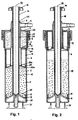
Im Beispiel von Fig. 1 und 2 besteht der Transportbehälter aus einem eigentlichen Behälter 6 und aus einem Behälterdeckel 7 der als Transportraum 4 für die Flüssigkomponente 1 ausgeführt ist, welcher Ringform hat und welcher mit einer Membran 3 in Form einer Kreisringfolie 16 verschlossen ist. Das Abfüllen der Flüssigkomponente 1 und Versiegeln des Transportraums 4 mit der Folie 16 geschieht in einer Voroperation. Zum weiteren Konfektionieren der Einrichtung wird:
Der Ausstosskolben 8im zylindrischen Behälter 6 eingepresst und mit einerSchnappverbindung 30 fixiert;der Mischkolben 11mit Kolbenstange 10auf dem Ausstosskolben 8 abgestellt;- die
Pulverkomponente 2 eingefüllt; der Verdrängerkörper 12 inden Behälter 6 eingesetzt und verklinkt, wobei der Verdrängerkörper 12eine Abdeckung 24mit zwei Führungslippen 25a, b besitzt, diedie Pulverkomponente 2 zurückhalten;der Deckel 7mit der Flüssigkomponente 1im Transportraum 4 über die hohle Kolbenstange 10 geführt und mit einerVerschraubung 23am Behälter 6 befestigt;ein Verschluss 14 in Form einer Ausbuchtung in die Kolbenstange eingeführt und der Behälter 6 verschlossen, wobei einzig eine Absaugöffnung 21 noch nicht verschlossen ist.
- The
ejection piston 8 is pressed into thecylindrical container 6 and fixed with asnap connection 30; - the
mixing piston 11 withpiston rod 10 placed on theejection piston 8; - filled the
powder component 2; - the
displacer body 12 is inserted and latched in thecontainer 6, thedisplacer body 12 having acover 24 with twoguide lips 25a, b which hold back thepowder component 2; - the
lid 7 with theliquid component 1 in thetransport space 4 is guided over thehollow piston rod 10 and fastened to thecontainer 6 with ascrew connection 23; - a
closure 14 in the form of a bulge is inserted into the piston rod and thecontainer 6 is closed, only onesuction opening 21 not yet being closed.
In diesem Zustand wäre die Vorrichtung gebrauchsfähig zum Mischen der beiden Komponenten. Bei Knochenzement wird die Einrichtung für Transport und Lagerung in eine Folie eingeschweisst und mit γ-Strahlen oder Gas, z.B. Ethylenoxid oder Formaldehyd sterilisiert. Die Teile der Vorrichtung sind als Spritzgussteile aus Kunststoff ausgeführt und transparent, um den Einfüllvorgang und später das Mischen überwachen zu können. Das Sterilisieren geschieht entweder vor dem Abfüllen mit γ-Strahlung, oder nachher mit Gas, damit die Flüssigkeit keinen Schaden durch γ-Strahlen nimmt.In this state the device would be usable for Mix the two components. With bone cement the device for transport and storage in a film welded in and with γ-rays or gas, e.g. Sterilized ethylene oxide or formaldehyde. The parts of the Device are injection molded plastic executed and transparent to the filling process and to be able to monitor the mixing later. The Sterilization is done either before filling γ-radiation, or afterwards with gas, so that the liquid does not take damage from γ-rays.
Bei Knochenzement wird die Vorrichtung steril in Operationsraum gebracht. Zum Mischen wird:
Der Mischkolben 11mit der Kolbenstange 10 aus einer Transportsicherung 22 heraus und durch diePulverkomponente 2 hindurchgezogen, wobei das fliessfähigePulver durch Schlitze 29am Mischkolben 11 vorbeifliesst;der Verdrängerkörper 12mit seiner Schneide 17durch den Mischkolben 11 aus seiner Schnappverbindung 20 herausgerissen und inden Transportraum 4 der Flüssigkomponente gepresst,wobei die Schneide 17 dieFolie 16 aufreisst und der Verdrängerkörper 12 dieFlüssigkomponente 1 vollständig inden Transportraum 5 der Pulverkomponente verdrängt;der Verdrängerkörper 12 in seiner Endstellung (Fig. 2)im Transportraum 5der Flüssigkomponente 1 blockiert, sodass nur noch Komponenten 1, 2 und Mischkolben 11 gegeneinander beweglich sind;- der Mischkolben unter Drehung eine vorgesehene Anzahl
Hübe, beispielsweise 30 Hübe, auf und ab gestossen, um
ein
Durchmischen der Komponenten - an der Absaugöffnung befristet ein Vakuum angesetzt, um Dämpfe und aufsteigende Luftblasen abzusaugen; und
der Verschluss 14 abgenommen, der Mischkolben 11 in einer oberen Position gehalten und ein Vorschubapparat mit Schubstange aneinem Bajonettverschluss 31 aufgesetzt, um die fertige Mischung 18mit dem Ausstosskolben 8 durch die hohle Kolbenstange 10 auszustossen.
- The
mixing piston 11 with thepiston rod 10 out of atransport lock 22 and pulled through thepowder component 2, the flowable powder flowing throughslots 29 past themixing piston 11; - the
displacer body 12 with itscutting edge 17 is torn out of itssnap connection 20 by themixing piston 11 and pressed into thetransport space 4 of the liquid component, thecutting edge 17 tearing open thefilm 16 and thedisplacer body 12 displacing theliquid component 1 completely into thetransport space 5 of the powder component; - the
displacement body 12 is blocked in its end position (FIG. 2) in thetransport space 5 of theliquid component 1, so thatonly components mixing piston 11 are movable relative to one another; - the mixing piston is rotated up and down a predetermined number of strokes, for example 30 strokes, in order to achieve a thorough mixing of
components - a vacuum is temporarily applied to the suction opening in order to extract vapors and rising air bubbles; and
- the
closure 14 is removed, themixing piston 11 is held in an upper position, and a feed device with a push rod is attached to abayonet closure 31 in order to eject thefinished mixture 18 with theejection piston 8 through thehollow piston rod 10.
Verschlussstopfen 14 und sein Handgriff lassen sich von
der Kolbenstange 10 abschrauben. Dadurch, dass die
meisten Teile zur Hauptachse 33 weitgehend
rotationssymmetrisch ausgeführt sind, ergeben sich
günstige Spritzformen.Sealing
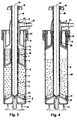
Im Beispiel von Fig. 3, 4 sind gegenüber dem
vorhergehenden Beispiel lediglich die Anordnung von
Verdrängerkörper 12 und des Transportraums 4 der
Flüssigkomponente 1 vertauscht. Behälter 6 und
Ausstosskolben 8 werden ebenfalls vormontiert. Der
Transportraum 4 für die Flüssigkomponente 1 ist ein
separater Behälter, der mit der Flüssigkomponente 1
gefüllt und mit einer Folie 3 geschlossen und
verschweisst wird. Zum Befüllen der Vorrichtung werden
Mischkolben 11 und Kolbenstange 10 im Behälter 6
eingesetzt. Anschliessend wird die Pulverkomponente 2
eingefüllt und der ringförmige Transportraum 4 der
Flüssigkomponente über die Kolbenstange 10 geschoben und
im Behälter 6 verankert. Der Deckel 7 mit dem
integrierten Verdrängerkörper 12 wird aufgesetzt und
verschliesst den Behälter 6 mit der Verschraubung 23. Als
letztes wird der Verschluss 14, der einen Handgriff und
eine Ausstülpung bis zum Mischkolben 11 aufweist, mit der
rohrförmigen Kolbenstange 10 über ein Gewinde beim
Handgriff verbunden. Die Ausstülpung 15 verhindert, dass
beim nachfolgenden Mischen, Toträume mit ungleicher
Verteilung der Komponenten 1, 2 entstehen.3, 4 are compared to the
previous example just the arrangement of
Zum eigentlichen Mischen Fig. 4 durchquert der
Mischkolben 11 die Pulverkomponente 2 und stösst den
Transportraum 4 der Flüssigkomponente in die Schneide 17
zum zerstören der Membran 3 und weiter über den
Verdrängerkörper 12, um die Flüssigkomponente 1
auszustossen. In ihrer Endstellung blockieren sich
Verdrängerkörper 12 und der Transportraum 4. Nach dem
Mischen mit dem Mischkolben 11 und dem eventuellen
Absaugen von Dämpfen über eine Absaugöffnung 21 wird der
Mischkolben 11 in einer oberen Stellung über die
Kolbenstange 10 fixiert und der Verschluss 14 mit
Handgriff und Ausstülpung 15 wird abgenommen. Nach dem
Ansetzen eines Vorschubapparates (hier nicht gezeigt) am
Bajonettverschluss 31 kann der gemischte Zement 18 durch
die konzentrisch zueinanderliegenden Oeffnungen 9, 34, 10
ausgestossen werden. 4 for the actual
Eine weitere Konstruktion ist in den Fig. 5, 6 und 7a bis
7i gezeigt. Die Vorrichtung besteht (Fig. 5, 6) aus einer
zu einer Längsachse 33 konzentrischen Anordnung mit einem
Behälter 6, der auf seiner Unterseite eine Oeffnung für
eine Nabe vom Ausstosskolben 8 aufweist und über einen
Bajonettverschluss 31 mit einem Vorschubapparat 27
(Fig. 7i) verbindbar ist. Auf seiner Oberseite ist der
Behälter 6 über eine Verschraubung 23 mit einem Deckel 7
verschlossen, welcher eine Oeffnung 9 besitzt, von der
eine Absaugöffnung 21 mit Filter 26 abzweigt. Der Deckel
7 ist gleichzeitig als Transportraum 4 für die
Flüssigkomponente 1 ausgeführt. An seiner Unterseite ist
er mit einer Membran 3 in Form einer ringförmigen Folie
16 verschlossen. An seiner Oberseite ist eine nicht
zentrische Einfüllöffnung 19 angebracht, die mit einem
Stopfen 42 verschliessbar ist. Ein Verdrängerkörper 12
ist in einer Transportstellung mit dem Behälter 6 über
eine Schnappverbindung 20 verbunden und besitzt ein
Ausflussrohr 41, welches durch die Oeffnung 9 im Deckel 7
herausgeführt ist. Das Ausflussrohr 41 ist mit einer
Ausstülpung 15 verschliessbar. Am Uebergang zwischen
Ausflussrohr und eigentlichem Verdrängerkörper 12 sind
Ausflussöffnungen 37 angebracht, die freigegeben werden,
wenn ein Mischkolben 11 die oberste Stellung gegenüber
dem Verdrängerkörper 12 erreicht und die Ausstülpung 15
zurückstösst. Konstruktiv ist das Ausflussrohr 41 ein
Teil von einer Abdeckung 24, die den hohlen
Verdrängerkörper 12 verschliesst. Der Mischkolben 11 ist
in seiner unteren Stellung mit dem Ausstosskolben 8 über
eine Verklinkung 40 verbindbar, wobei der Ausstosskolben
8 in seiner unteren Stellung über eine Drehsicherung 39
zum Behälter 6 Drehmomente aufnehmen kann. Der
Ausstosskolben 8 besitzt an seiner Nabe eine zentrale
Bohrung durch die ein Stück der Kolbenstange 10 für den
Mischkolben 11 in Form einer Hülse mit Gewinde
herausgeführt ist. Die eigentliche Kolbenstange 10
besitzt einen Handgriff 32 und einen Anschlag 48. Sie ist
über ein Gewinde mit dem Mischkolben 11 verschraubbar.Another construction is in Figs. 5, 6 and 7a to
7i. The device consists (Fig. 5, 6) of a
to a
Fig. 7a zeigt die Vorrichtung im vormontierten Zustand.
Der Ausstosskolben 8 ist eingesetzt. Der Mischkolben 11
ist in der untersten Stellung mit dem Ausstosskolben 8
verklinkt und seine Kolbenstange 10 ist eingesetzt. Der
Verdrängerkörper 12 mit Ausflussrohr 41 ist mit dem
Behälter 6 in Transportstellung verbunden. Der Deckel 7
ist mit dem Behälter 6 verschraubt.7a shows the device in the preassembled state.
The
In Fig. 7b wird durch eine Abfüllöffnung 19 im Deckel 7
die Flüssigkomponente 1 eingefüllt und die Abfüllöffnung
mit einem Stopfen 42 verschlossen. Für grössere Serien
erfolgt das Abfüllen an einer Abfüllstation mit
Tauchsonde und vorportionierten Flüssigkeitsmengen.7b, through a filling
In Fig. 7c wird die Pulverkomponente 2 in ihren
Transportraum 5 im Behälter 6 durch das Ausflussrohr 41
eingefüllt. Um die Ausflussöffnungen 3 am
Verdrängerkörper 12 nicht zuzusetzen und um
Staubentwicklungen zu vermeiden, ist eine Tauchsonde, die
zum Abfüllen in den Transportraum 5 ragt, vorteilhaft.7c shows the
In Fig. 7d ist der gefüllte Behälter 6 mit der
Ausstülpung 15 verschlossen und kann zum Beispiel für
Knochenzement in dieser Anordnung in einer Folie
eingeschweisst und sterilisiert werden. Die Vorrichtung
ist in dieser Anordnung transportierbar und lagerbar und
jederzeit für ein Mischen und Ausstossen vom
Zweikomponentenmaterial 1, 2 betriebsbereit.In Fig. 7d, the filled
Zum Mischen wird die Vorrichtung mit dem
abwärtsgerichteten Handgriff 32 auf eine Gegenfläche
gepresst, um die Verklinkung 40 zwischen Mischkolben und
Ausstosskolben zu lösen. Der Mischkolben durchquert die
Pulverkomponente 2 und trifft auf der Ausstülpung 15 auf,
die soweit gegen aussen herausgestossen wird (Fig. 7e),
dass die Ausflussöffnungen 37 für die Flüssigkomponente 1
freigelegt werden. Gleichzeitig wird der Verdrängerkörper
12 aus seiner Schnappverbindung 20 gerissen und zerstört
mit seiner Schneide die Folie des Transportraums 4 der
Flüssigkomponente, um die Flüssigkomponente 1 vollständig
zu verdrängen. Diese fliesst durch die Ausflussöffnungen
37 in den Transportraum 5 der Pulverkomponente.
Verdrängerkörper 12 und Ausflussrohr 41 blockieren sich
in einer obersten Stellung und das eigentliche
Durchmischen (Fig. 7f) kann stattfinden. Dazu wird der
Mischkolben 11 unter Drehung über eine vorgegebene Anzahl
Hübe auf und ab bewegt und beide Komponenten werden unter
gegenseitiger Reibung durch Schlitze 29 am Mischkolben 11
gepresst.For mixing the device with the
In Fig. 7g wurde der Mischkolben 11 in der untersten
Stellung am Ausstosskolben verklinkt 40, um die
Kolbenstange 10 mit dem Handgriff 32 vom Mischkolben 11
abzuschrauben. Das dazu notwendige Gegenmoment wird vom
Behälter 6 über die Drehsicherung 39 auf den
Ausstosskolben 8 und von diesem über die Verklinkung 40
auf den Mischkolben übertragen.In Fig. 7g, the
In Fig. 7h ist an der Absaugöffnung 21 ein Schlauch zum
Absaugen von Lösungsmitteldämpfen angesetzt, wobei ein
Filter 26 ein Vordringen von festen oder zähflüssigen
Partikeln verhindert.In Fig. 7h is a hose to the
In Fig. 7i wurde ein nicht weiter gezeigter
Vorschubapparat 27 am Bajonettverschluss 31 angesetzt.
Dieser wirkt mit einer Schubstange 44 auf den
Ausstosskolben 8. Sobald die Ausstülpung 15 vollständig
entfernt ist, kann der noch flüssige Zement über eine
Mündung 43 vom Ausflussrohr 41 ausgepresst werden.In Fig. 7i a not shown
Ein weiteres Beispiel ist in den Fig. 8, 9 und 10a bis j
gezeigt. In Fig. 8 ist eine betriebsbereite Vorrichtung
dargestellt. Der Behälter 6 ist auf der Unterseite durch
den Ausstosskolben 8 verschlossen, auf welchem der
Mischkolben 11 aufliegt. Der Mischkolben 11 wird über
eine Kolbenstange 10 betätigt, die eine lösbare
Verbindung 45 zum Mischkolben 11 aufweist und die nach
oben aus dem Behälterdeckel 7 herausgeführt ist und mit
einem Handgriff 32 abschliesst. Der Transportraum 5 für
die Pulverkomponente 2 wird nach oben durch einen
eingepressten Ableitring 35 und durch einen Schleppring
36 abgeschlossen. Am ortsfesten Ableitring 35 sind
einige, zum Beispiel vier, Schneiden 17 angebracht und
eine Verklinkung 40 für den Mischkolben 11. Der
Schleppring 36 kann nur unter Ueberwindung einer
Klemmkraft in axialer Richtung bewegt werden. Er
blockiert sich mit seiner obersten Stellung im Deckel 7
und ist dann nur noch mit dem Deckel bewegbar. Der Deckel
7 besitzt einen mittleren Durchbruch 34, durch den die
Kolbenstange 10 einsteckbar und ausziehbar ist. Nach dem
Mischen und dem Ausziehen der Kolbenstange kann der
Zement durch diesen mittleren Durchbruch 34 und die daran
anschliessende Oeffnung 9 ausgestossen werden. Der Deckel
7 ist als ringförmiger Transportraum 4 für die
Flüssigkomponente 1 ausgeführt und auf seiner Unterseite
mit einer Folie 16 verschlossen. Der Deckel ist in
radialer Richtung in Aussparungen in Form einer Wendel 38
gelagert und kann um etwa 60° vorwärts und rückwärts
gegenüber dem Behälter 6 gedreht werden, wobei er einen
Hub von etwa 6 mm ausführt. Another example is in Figs. 8, 9 and 10a to j
shown. In Fig. 8 is an operational device
shown. The
In Fig. 9 ist der Zement 18 bereits gemischt. Der
Mischkolben 11 ist in seiner obersten Position über die
Verklinkung 40 mit dem Ableitring 35 verbunden. Die
Kolbenstange 10 ist durch Lösen der Verbindung 45
ausgezogen worden und stattdessen ist ein Ausflussrohr 41
mit Mündung 43 über eine Kupplung 46 am Deckel 7
angesetzt worden. Der Deckel 7 befindet sich in seiner
unteren Position gegenüber dem Behälter 6 und sichert den
Schleppring 36.In Fig. 9 the
In Fig. 10a ist der Anlieferzustand der Vorrichtung vor
dem Abfüllen gezeigt. Am Behälter 6 ist der
Ausstosskolben 8 eingesetzt. Ebenso wurde der Ableitring
35 mit dem verklinkten Mischkolben 11 mit einer dosierten
Kraft auf einer Presse eingepresst. Der Deckel 7 ist
bereits mit einer Folie 16 versiegelt und mit dem
eingesetzten Schleppring 36 in seiner oberen Stellung
gegenüber dem Behälter 6 aufgesteckt worden und besitzt
noch eine Oeffnung 19 zum Abfüllen. Verschlussstopfen 42
und Kolbenstange 10 mit Handgriff 32 werden lose
mitgeliefert.The delivery state of the device is shown in FIG. 10a
shown the bottling. On the
In Fig. 10b wird die Flüssigkomponente 1 in ihren
Transportraum 4 abgefüllt. Eine Abfüllsonde ist auch hier
von Vorteil. Allerdings darf sie die Verschlussfolie 16
nicht beschädigen.In Fig. 10b the
In Fig. 10c ist der Transportraum 4 der Flüssigkomponente
1 bereits mit dem Stopfen 42 verschlossen und der
Transportraum 5 der Pulverkomponente 2 wird aufgefüllt.
Auch hier ist eine Tauchsonde zum Abfüllen von Vorteil.10c is the
In Fig. 10d wurde die Kolbenstange 10 in den abgefüllten
Behälter 6 von oben eingesetzt und in ihrer tiefsten
Position über einen Kragen mit dem Behälterdeckel 7
verbunden. Beim Abwärtsfahren wurde der Mischkolben aus
seiner Verklinkung 40 gelöst und mitgenommen.
Gleichzeitig wurde eine lösbare Verbindung 45 zur
Kolbenstange 10 hergestellt. Das Gerät wäre jetzt für ein
Mischen betriebsbereit und kann in dieser Form gelagert
und transportiert werden.In Fig. 10d, the
In Fig. 10e wird die Flüssigkomponente 1 durch eine erste
Vorwärtsdrehung und sofort anschliessende
Rückwärtsdrehung des Deckels 7 freigesetzt. Beim
Vorwärtsdrehen entlang der Wendel 38 taucht der
Transportbehälter 4 mit der Folie 16 in die Schneiden 17
und wird aufgerissen. Gleichzeitig schiebt sich der
Deckel 7 auf den Schleppring und hält diesen fest. Beim
sofort anschliessenden Zurückdrehen hebt der Deckel 7 den
Schleppring ab und gibt eine ringförmige Ausflussöffnung
37 für die Flüssigkomponente frei, welche nun unter
Schwerkraft in den Transportraum 5 der Pulverkomponente 2
ausfliesst. Nach dem vollständigen Ausfliessen der
Flüssigkomponente, was bei transparentem Behälterdeckel 7
kontrollierbar ist, erfolgt eine zweite Vorwärtsdrehung
des Deckels 7, die den Schleppring 36 gegen den
Ableitring 35 presst und so beide Komponenten 1, 2 im
Transportraum 5 der Pulverkomponente 2 für das Mischen
einschliesst (Fig. 10f).In Fig. 10e the
In Fig. 10g findet das eigentliche Mischen über Handgriff
32, Kolbenstange 10 und den Mischkolben 11 statt. Nach
Abschluss der vorgesehenen Hubbewegungen wird die
Kolbenstange 10 ganz nach oben gezogen (Fig. 10h). Der
Mischkolben 11 fährt wieder in die Verklinkung 40 am
Ableitring 35 ein und die Kolbenstange 10 löst sich aus
ihrer Verbindung 45 am Mischkolben 11. Fakultativ kann
anschliessend ein Absaugrohr 47 am Deckel 7 aufgesetzt
werden (Fig. 10i), um Lösungsmitteldämpfe und Luftblasen
vom gemischten Zement 18 abzusaugen.In Fig. 10g the actual mixing takes place via
In Fig. 10j ist statt dem Absaugrohr 47 ein Ausflussrohr
41 mit einer Kupplung 46 befestigt. Auf der Unterseite
ist ein Vorschubapparat 27 am Behälter befestigt worden,
der mit einer Schubstange 44 den Zement über eine Mündung
43 am Ausflussrohr 41 ausstossen kann.10j is an outflow pipe instead of the
Claims (19)
Priority Applications (6)
| Application Number | Priority Date | Filing Date | Title |
|---|---|---|---|
| EP97810352A EP0882436B1 (en) | 1997-06-05 | 1997-06-05 | Transport and process device for two-component material |
| ES97810352T ES2182016T3 (en) | 1997-06-05 | 1997-06-05 | TRANSPORTATION AND TREATMENT DEVICE FOR A MATERIAL OF TWO COMPONENTS. |
| AT97810352T ATE222481T1 (en) | 1997-06-05 | 1997-06-05 | TRANSPORT AND PROCESSING DEVICE FOR TWO-COMPONENT MATERIAL |
| DE59708011T DE59708011D1 (en) | 1997-06-05 | 1997-06-05 | Transport and processing device for two-component material |
| US09/082,849 US6017349A (en) | 1997-06-05 | 1998-05-21 | Transport and processing apparatus for a two-component material |
| JP10141244A JPH114836A (en) | 1997-06-05 | 1998-05-22 | Transporting and processing device and method for two-component material |
Applications Claiming Priority (1)
| Application Number | Priority Date | Filing Date | Title |
|---|---|---|---|
| EP97810352A EP0882436B1 (en) | 1997-06-05 | 1997-06-05 | Transport and process device for two-component material |
Publications (2)
| Publication Number | Publication Date |
|---|---|
| EP0882436A1 true EP0882436A1 (en) | 1998-12-09 |
| EP0882436B1 EP0882436B1 (en) | 2002-08-21 |
Family
ID=8230252
Family Applications (1)
| Application Number | Title | Priority Date | Filing Date |
|---|---|---|---|
| EP97810352A Expired - Lifetime EP0882436B1 (en) | 1997-06-05 | 1997-06-05 | Transport and process device for two-component material |
Country Status (6)
| Country | Link |
|---|---|
| US (1) | US6017349A (en) |
| EP (1) | EP0882436B1 (en) |
| JP (1) | JPH114836A (en) |
| AT (1) | ATE222481T1 (en) |
| DE (1) | DE59708011D1 (en) |
| ES (1) | ES2182016T3 (en) |
Cited By (9)
| Publication number | Priority date | Publication date | Assignee | Title |
|---|---|---|---|---|
| GB2352408A (en) * | 1999-07-27 | 2001-01-31 | Summit Medical Ltd | Pre-filled orthopaedic bone cement container in which the cement can also be mixed |
| WO2001070146A2 (en) * | 2000-02-28 | 2001-09-27 | Coripharm Medizinprodukte Gmbh & Co. Kg | Preparation and application device for implant materials |
| WO2001085070A1 (en) * | 2000-05-05 | 2001-11-15 | Coripharm Medizinprodukte Gmbh & Co. Kg | Preparation and application device for materials to be prepared as a paste-like flowable mass, especially bone cement |
| WO2008022481A1 (en) * | 2006-08-22 | 2008-02-28 | Medmix Systems Ag | Device and method for storing, mixing and dispensing components |
| EP2008707A1 (en) * | 2007-06-04 | 2008-12-31 | Aap Biomaterials GmbH & Co. KG | Mixing and application device of a mixture, in particular of medical or bone cement |
| EP2265317A2 (en) * | 2008-04-11 | 2010-12-29 | Applied Silicone Corporation | Gas sterilizable two-part polymer delivery system |
| EP2902098A1 (en) * | 2014-02-03 | 2015-08-05 | Heraeus Medical GmbH | Device and process for storing and mixing bone cement |
| EP3178546A1 (en) * | 2015-12-07 | 2017-06-14 | Heraeus Medical GmbH | Mixing device with operating element and pressure pump for mixing polymethylmethacrylate bone cement |
| EP3178547A1 (en) * | 2015-12-07 | 2017-06-14 | Heraeus Medical GmbH | Vaccum mixing device with operating element, pressure pump, and vakuum pump for mixing polymethylmethacrylate bone cement |
Families Citing this family (47)
| Publication number | Priority date | Publication date | Assignee | Title |
|---|---|---|---|---|
| SE9301599L (en) * | 1993-05-10 | 1994-06-27 | Cemvac System Ab | Device for loading bone cement components into a pressurized mixing vessel |
| US6536937B1 (en) * | 2000-02-14 | 2003-03-25 | Telios Orthopedic Systems, Inc. | Self-contained base for a surgical cement mixing system, binding material mixing base, and surgical bone cement mixing system |
| US6379033B1 (en) | 2000-05-30 | 2002-04-30 | William M. Murray | Device for flowing bone cement liquid into bone cement powder |
| US6655828B2 (en) * | 2000-12-01 | 2003-12-02 | Depuy Orthopaedics, Inc. | Bone cement mixing apparatus having improved mixing blade configuration |
| US7008433B2 (en) * | 2001-02-15 | 2006-03-07 | Depuy Acromed, Inc. | Vertebroplasty injection device |
| CA2449970A1 (en) | 2001-06-14 | 2002-12-27 | Cemvac System Ab | Method and device for preparation of bone cement |
| FR2829690B1 (en) * | 2001-09-19 | 2003-12-19 | Inoteb | DEVICE FOR PLACING A BIOMATERIAL |
| US7029163B2 (en) * | 2002-10-07 | 2006-04-18 | Advanced Biomaterial Systems, Inc. | Apparatus for mixing and dispensing components |
| US7179264B2 (en) * | 2002-08-28 | 2007-02-20 | Depuy Products, Inc. | Cemented prosthetic kit |
| JP4533886B2 (en) * | 2003-02-21 | 2010-09-01 | オステオバイオロジックス, インコーポレイテッド | Bone and cartilage implant delivery device |
| US20060264967A1 (en) | 2003-03-14 | 2006-11-23 | Ferreyro Roque H | Hydraulic device for the injection of bone cement in percutaneous vertebroplasty |
| US8066713B2 (en) | 2003-03-31 | 2011-11-29 | Depuy Spine, Inc. | Remotely-activated vertebroplasty injection device |
| US20050128867A1 (en) * | 2003-05-12 | 2005-06-16 | Henniges Bruce D. | Bone cement mixing and delivery system |
| US20040267272A1 (en) | 2003-05-12 | 2004-12-30 | Henniges Bruce D | Bone cement mixing and delivery system |
| US20070032567A1 (en) * | 2003-06-17 | 2007-02-08 | Disc-O-Tech Medical | Bone Cement And Methods Of Use Thereof |
| US8415407B2 (en) | 2004-03-21 | 2013-04-09 | Depuy Spine, Inc. | Methods, materials, and apparatus for treating bone and other tissue |
| WO2006011152A2 (en) * | 2004-06-17 | 2006-02-02 | Disc-O-Tech Medical Technologies, Ltd. | Methods for treating bone and other tissue |
| WO2005030034A2 (en) * | 2003-09-26 | 2005-04-07 | Depuy Spine, Inc. | Device for delivering viscous material |
| CA2481663A1 (en) * | 2003-10-01 | 2005-04-01 | Biomet Deutschland Gmbh | Device for the mixing and discharge of liquid and pulverulent materials for medical use |
| WO2005053581A1 (en) * | 2003-12-01 | 2005-06-16 | Broockeville Corporation N.V. | A tow-component mixing and dispensing device |
| US20050282117A1 (en) * | 2004-05-05 | 2005-12-22 | Aravena Ines M | Systems and methods for dispensing sealant in medical applications |
| US8038682B2 (en) * | 2004-08-17 | 2011-10-18 | Boston Scientific Scimed, Inc. | Apparatus and methods for delivering compounds into vertebrae for vertebroplasty |
| US20080319445A9 (en) * | 2004-08-17 | 2008-12-25 | Scimed Life Systems, Inc. | Apparatus and methods for delivering compounds into vertebrae for vertebroplasty |
| ES2309743T3 (en) * | 2005-04-11 | 2008-12-16 | Broockeville Corporation N.V. | MIXING WITH TWO COMPONENTS AND DISPENSING DEVICE. |
| CN101166487A (en) * | 2005-04-29 | 2008-04-23 | 惠氏公司 | Drug delivery devices and related components, systems and methods |
| US7513901B2 (en) * | 2005-05-19 | 2009-04-07 | Warsaw Orthopedic, Inc. | Graft syringe assembly |
| ITVI20050152A1 (en) * | 2005-05-20 | 2006-11-21 | Tecres Spa | CARTRIDGE FOR CONSERVATION AND STERILE DISTRIBUTION OF A BIPHASIC COMPOUND, PARTICULARLY FOR AN ACRYLIC RESIN |
| US20060274601A1 (en) * | 2005-06-07 | 2006-12-07 | Seaton James P Jr | Prepacked cartridge mixing system |
| ITVI20050187A1 (en) * | 2005-06-28 | 2006-12-29 | Tecres Spa | CARTRIDGE FOR STERILE MIXING OF A BIPHASIC COMPOUND, PERTICULARLY FOR BICOMPONENT ACRYLIC RESINS |
| US9381024B2 (en) * | 2005-07-31 | 2016-07-05 | DePuy Synthes Products, Inc. | Marked tools |
| US9918767B2 (en) | 2005-08-01 | 2018-03-20 | DePuy Synthes Products, Inc. | Temperature control system |
| US8360629B2 (en) | 2005-11-22 | 2013-01-29 | Depuy Spine, Inc. | Mixing apparatus having central and planetary mixing elements |
| US7758556B2 (en) * | 2006-03-23 | 2010-07-20 | Perez-Cruet Miguelangelo J | Device for collecting bone material during a surgical procedure |
| WO2008030742A2 (en) * | 2006-09-07 | 2008-03-13 | Wyeth | Bone cement mixing systems and related methods |
| WO2008032322A2 (en) | 2006-09-14 | 2008-03-20 | Depuy Spine, Inc. | Bone cement and methods of use thereof |
| AU2007311451A1 (en) | 2006-10-19 | 2008-04-24 | Depuy Spine, Inc. | Fluid delivery system |
| US20090054906A1 (en) * | 2007-08-24 | 2009-02-26 | Zimmer Orthobiologics, Inc. | Medical device and method for delivering an implant to an anatomical site |
| SE531600C2 (en) * | 2007-10-10 | 2009-06-02 | Ortoviva Ab | Mixing system and mixing procedure for medical purposes |
| US20090264895A1 (en) * | 2008-04-22 | 2009-10-22 | Warsaw Orthopedic, Inc. | Systems and methods for implanting a bone fastener and delivering a bone filling material |
| SE0801728A0 (en) * | 2008-07-23 | 2010-01-24 | Olerud Sven | A syringe for closed and sterile mixing of two components |
| US8435305B2 (en) | 2010-08-31 | 2013-05-07 | Zimmer, Inc. | Osteochondral graft delivery device and uses thereof |
| DE102016110564B4 (en) * | 2016-06-08 | 2018-05-09 | Heraeus Medical Gmbh | Storage and mixing device for bone cement with pressure pump |
| DE102016110561A1 (en) * | 2016-06-08 | 2017-12-14 | Heraeus Medical Gmbh | Storage and mixing device for producing a bone cement |
| EP3661660A4 (en) | 2017-08-04 | 2021-05-19 | Mark Robert Towler | A storage, mixing and dispensing device |
| EP3643398B1 (en) | 2018-10-25 | 2021-07-07 | Heraeus Medical GmbH | Device and method for producing bone cement |
| DE102018131266B4 (en) * | 2018-12-07 | 2021-12-23 | Heraeus Medical Gmbh | Apparatus for mixing a bone cement with a cavity for monomer transfer and a process for the production of a bone cement dough |
| DE102018131268B4 (en) * | 2018-12-07 | 2021-11-25 | Heraeus Medical Gmbh | Device for mixing a bone cement with a cavity for monomer transfer |
Citations (2)
| Publication number | Priority date | Publication date | Assignee | Title |
|---|---|---|---|---|
| WO1987005492A1 (en) * | 1986-03-21 | 1987-09-24 | Klaus Draenert | Device and process for mixing and filling with bone cement |
| EP0397589A1 (en) * | 1989-05-12 | 1990-11-14 | Wolff & Kaaber A/S | A method and device for preparing a mixture of a solid and a liquid component |
Family Cites Families (2)
| Publication number | Priority date | Publication date | Assignee | Title |
|---|---|---|---|---|
| US4751921A (en) * | 1985-10-21 | 1988-06-21 | University Of Iowa Research Foundation | Bone cement syringe |
| US5681317A (en) * | 1996-06-12 | 1997-10-28 | Johnson & Johnson Professional, Inc. | Cement delivery system and method |
-
1997
- 1997-06-05 DE DE59708011T patent/DE59708011D1/en not_active Expired - Fee Related
- 1997-06-05 AT AT97810352T patent/ATE222481T1/en not_active IP Right Cessation
- 1997-06-05 ES ES97810352T patent/ES2182016T3/en not_active Expired - Lifetime
- 1997-06-05 EP EP97810352A patent/EP0882436B1/en not_active Expired - Lifetime
-
1998
- 1998-05-21 US US09/082,849 patent/US6017349A/en not_active Expired - Lifetime
- 1998-05-22 JP JP10141244A patent/JPH114836A/en active Pending
Patent Citations (2)
| Publication number | Priority date | Publication date | Assignee | Title |
|---|---|---|---|---|
| WO1987005492A1 (en) * | 1986-03-21 | 1987-09-24 | Klaus Draenert | Device and process for mixing and filling with bone cement |
| EP0397589A1 (en) * | 1989-05-12 | 1990-11-14 | Wolff & Kaaber A/S | A method and device for preparing a mixture of a solid and a liquid component |
Cited By (17)
| Publication number | Priority date | Publication date | Assignee | Title |
|---|---|---|---|---|
| GB2352408B (en) * | 1999-07-27 | 2001-07-11 | Summit Medical Ltd | Orthopaedic bone cement mixing container |
| GB2352408A (en) * | 1999-07-27 | 2001-01-31 | Summit Medical Ltd | Pre-filled orthopaedic bone cement container in which the cement can also be mixed |
| WO2001070146A2 (en) * | 2000-02-28 | 2001-09-27 | Coripharm Medizinprodukte Gmbh & Co. Kg | Preparation and application device for implant materials |
| WO2001070146A3 (en) * | 2000-02-28 | 2002-03-14 | Coripharm Medizinprodukte Gmbh | Preparation and application device for implant materials |
| US6796701B2 (en) * | 2000-02-28 | 2004-09-28 | Coripharm Medizinprodukte Gmbh & Co. Kg | Preparation and application device for implant materials with hand-operated pump |
| WO2001085070A1 (en) * | 2000-05-05 | 2001-11-15 | Coripharm Medizinprodukte Gmbh & Co. Kg | Preparation and application device for materials to be prepared as a paste-like flowable mass, especially bone cement |
| US8256646B2 (en) | 2006-08-22 | 2012-09-04 | Medmix Systems Ag | Device and method for storing, mixing and dispensing components |
| WO2008022481A1 (en) * | 2006-08-22 | 2008-02-28 | Medmix Systems Ag | Device and method for storing, mixing and dispensing components |
| EP2008707A1 (en) * | 2007-06-04 | 2008-12-31 | Aap Biomaterials GmbH & Co. KG | Mixing and application device of a mixture, in particular of medical or bone cement |
| EP2265317A2 (en) * | 2008-04-11 | 2010-12-29 | Applied Silicone Corporation | Gas sterilizable two-part polymer delivery system |
| EP2265317A4 (en) * | 2008-04-11 | 2012-10-10 | Applied Silicone Corp | Gas sterilizable two-part polymer delivery system |
| US8435217B2 (en) | 2008-04-11 | 2013-05-07 | Applied Silicone Corporation | Gas sterilizable two-part polymer delivery system |
| EP2902098A1 (en) * | 2014-02-03 | 2015-08-05 | Heraeus Medical GmbH | Device and process for storing and mixing bone cement |
| US10010362B2 (en) | 2014-02-03 | 2018-07-03 | Heraeus Medical Gmbh | Device for storing and mixing bone cement |
| EP3178546A1 (en) * | 2015-12-07 | 2017-06-14 | Heraeus Medical GmbH | Mixing device with operating element and pressure pump for mixing polymethylmethacrylate bone cement |
| EP3178547A1 (en) * | 2015-12-07 | 2017-06-14 | Heraeus Medical GmbH | Vaccum mixing device with operating element, pressure pump, and vakuum pump for mixing polymethylmethacrylate bone cement |
| US10065160B2 (en) | 2015-12-07 | 2018-09-04 | Heraeus Medical Gmbh | Vacuum mixing device with operating element, pressure pump, and vacuum pump for mixing polymethylmethacrylate bone cement |
Also Published As
| Publication number | Publication date |
|---|---|
| ATE222481T1 (en) | 2002-09-15 |
| JPH114836A (en) | 1999-01-12 |
| ES2182016T3 (en) | 2003-03-01 |
| EP0882436B1 (en) | 2002-08-21 |
| US6017349A (en) | 2000-01-25 |
| DE59708011D1 (en) | 2002-09-26 |
Similar Documents
| Publication | Publication Date | Title |
|---|---|---|
| EP0882436B1 (en) | Transport and process device for two-component material | |
| DE69822216T2 (en) | MULTIPLE SYRINGE FOR MANUAL APPLICATION OF SUBSTANCES | |
| EP0313519B1 (en) | Device for dispensing and mixing at least two reactive components | |
| EP0692229B1 (en) | Mixing and dispensing device for bone cement | |
| EP0808148B1 (en) | Transfer device | |
| EP0663348B1 (en) | Device for emptying a tubular bag | |
| EP2520360B1 (en) | Mixer for mixing at least two flowable components, and application device | |
| EP1140259B1 (en) | Multi-chambered ampoule for dispensing a mixture comprising several substances | |
| DE69824018T2 (en) | ASEPTIC CONNECTING DEVICE | |
| EP0810164B1 (en) | Apparatus for preparation of a mixture of an active substance and a diluent, as well as a method of filling a cartridge for such an apparatus | |
| DE3611690A1 (en) | DISCHARGE DEVICE FOR MIXED MEDIA | |
| DE2648795A1 (en) | PRE-FILLED, EASILY READY TO USE INJECTION SYRINGE | |
| DE19606163A1 (en) | Container for two substances | |
| EP1616590B1 (en) | Multichamber ampoule for dispensing a mixture consisting of multiple substances | |
| CH627642A5 (en) | CONTAINER WITH LOCK. | |
| EP2928811B1 (en) | Apparatus for emptying containers | |
| DE3237353A1 (en) | Device for mixing dental compounds | |
| DE3535986A1 (en) | System for preparing an active substance/solvent mixture | |
| EP0064949A1 (en) | Container closure for a tapping unit | |
| DE3208786A1 (en) | Two-chamber container with a destructible partition wall | |
| EP1590263B1 (en) | One-piece double-chamber container | |
| EP0330723B1 (en) | Multi-chamber container | |
| DE2944443C2 (en) | Device for emptying a flowable or pourable mass contained in an open, cylindrical container | |
| DE60211447T2 (en) | System and device for mixing impression materials for dental applications and the like | |
| DE102019203858A1 (en) | Packaging system for at least one product preparation component and the associated method for handling the product preparation component |
Legal Events
| Date | Code | Title | Description |
|---|---|---|---|
| PUAI | Public reference made under article 153(3) epc to a published international application that has entered the european phase |
Free format text: ORIGINAL CODE: 0009012 |
|
| AK | Designated contracting states |
Kind code of ref document: A1 Designated state(s): AT BE CH DE ES FR GB IT LI NL SE |
|
| AX | Request for extension of the european patent |
Free format text: AL;LT;LV;RO;SI |
|
| 17P | Request for examination filed |
Effective date: 19990511 |
|
| AKX | Designation fees paid |
Free format text: AT BE CH DE DK ES FI FR GB GR LI |
|
| RBV | Designated contracting states (corrected) |
Designated state(s): AT BE CH DE ES FR GB IT LI NL SE |
|
| GRAG | Despatch of communication of intention to grant |
Free format text: ORIGINAL CODE: EPIDOS AGRA |
|
| 17Q | First examination report despatched |
Effective date: 20011019 |
|
| GRAG | Despatch of communication of intention to grant |
Free format text: ORIGINAL CODE: EPIDOS AGRA |
|
| GRAH | Despatch of communication of intention to grant a patent |
Free format text: ORIGINAL CODE: EPIDOS IGRA |
|
| GRAH | Despatch of communication of intention to grant a patent |
Free format text: ORIGINAL CODE: EPIDOS IGRA |
|
| GRAA | (expected) grant |
Free format text: ORIGINAL CODE: 0009210 |
|
| AK | Designated contracting states |
Kind code of ref document: B1 Designated state(s): AT BE CH DE ES FR GB IT LI NL SE |
|
| REF | Corresponds to: |
Ref document number: 222481 Country of ref document: AT Date of ref document: 20020915 Kind code of ref document: T |
|
| REG | Reference to a national code |
Ref country code: GB Ref legal event code: FG4D Free format text: NOT ENGLISH |
|
| REG | Reference to a national code |
Ref country code: CH Ref legal event code: EP |
|
| GBT | Gb: translation of ep patent filed (gb section 77(6)(a)/1977) |
Effective date: 20020821 |
|
| REF | Corresponds to: |
Ref document number: 59708011 Country of ref document: DE Date of ref document: 20020926 |
|
| ET | Fr: translation filed | ||
| REG | Reference to a national code |
Ref country code: ES Ref legal event code: FG2A Ref document number: 2182016 Country of ref document: ES Kind code of ref document: T3 |
|
| PLBE | No opposition filed within time limit |
Free format text: ORIGINAL CODE: 0009261 |
|
| STAA | Information on the status of an ep patent application or granted ep patent |
Free format text: STATUS: NO OPPOSITION FILED WITHIN TIME LIMIT |
|
| 26N | No opposition filed |
Effective date: 20030522 |
|
| REG | Reference to a national code |
Ref country code: CH Ref legal event code: PUE Owner name: ZIMMER GMBH Free format text: SULZER ORTHOPAEDIE AG#GRABENSTRASSE 25#6340 BAAR (CH) -TRANSFER TO- ZIMMER GMBH#SULZER ALLEE 8#8404 WINTERTHUR (CH) |
|
| NLS | Nl: assignments of ep-patents |
Owner name: ZIMMER GMBH Effective date: 20061010 Owner name: SULZER ORTHOPEDICS LTD. Effective date: 20061010 |
|
| NLT1 | Nl: modifications of names registered in virtue of documents presented to the patent office pursuant to art. 16 a, paragraph 1 |
Owner name: SULZER MEDICA AG Owner name: CENTERPULSE ORTHOPEDICS LTD. |
|
| REG | Reference to a national code |
Ref country code: FR Ref legal event code: TP Ref country code: FR Ref legal event code: CD Ref country code: FR Ref legal event code: CA |
|
| BECA | Be: change of holder's address |
Owner name: *ZIMMER G.M.B.H.SULZER ALLEE 8, CH-8404 WINTERTHUR Effective date: 20060802 |
|
| BECH | Be: change of holder |
Owner name: *ZIMMER G.M.B.H. Effective date: 20060802 |
|
| BECN | Be: change of holder's name |
Owner name: *ZIMMER G.M.B.H.SULZER ALLEE 8, CH-8404 WINTERTHUR Effective date: 20060802 Owner name: *ZIMMER G.M.B.H. Effective date: 20060802 |
|
| PGFP | Annual fee paid to national office [announced via postgrant information from national office to epo] |
Ref country code: ES Payment date: 20080627 Year of fee payment: 12 Ref country code: CH Payment date: 20080613 Year of fee payment: 12 |
|
| PGFP | Annual fee paid to national office [announced via postgrant information from national office to epo] |
Ref country code: AT Payment date: 20080616 Year of fee payment: 12 |
|
| PGFP | Annual fee paid to national office [announced via postgrant information from national office to epo] |
Ref country code: IT Payment date: 20080625 Year of fee payment: 12 |
|
| PGFP | Annual fee paid to national office [announced via postgrant information from national office to epo] |
Ref country code: SE Payment date: 20080612 Year of fee payment: 12 Ref country code: NL Payment date: 20080618 Year of fee payment: 12 Ref country code: DE Payment date: 20080620 Year of fee payment: 12 |
|
| PGFP | Annual fee paid to national office [announced via postgrant information from national office to epo] |
Ref country code: FR Payment date: 20080613 Year of fee payment: 12 |
|
| PGFP | Annual fee paid to national office [announced via postgrant information from national office to epo] |
Ref country code: GB Payment date: 20080620 Year of fee payment: 12 |
|
| PGFP | Annual fee paid to national office [announced via postgrant information from national office to epo] |
Ref country code: BE Payment date: 20080728 Year of fee payment: 12 |
|
| BERE | Be: lapsed |
Owner name: *ZIMMER G.M.B.H. Effective date: 20090630 |
|
| REG | Reference to a national code |
Ref country code: CH Ref legal event code: PL |
|
| REG | Reference to a national code |
Ref country code: GB Ref legal event code: 732E Free format text: REGISTERED BETWEEN 20100121 AND 20100127 |
|
| GBPC | Gb: european patent ceased through non-payment of renewal fee |
Effective date: 20090605 |
|
| NLV4 | Nl: lapsed or anulled due to non-payment of the annual fee |
Effective date: 20100101 |
|
| REG | Reference to a national code |
Ref country code: FR Ref legal event code: ST Effective date: 20100226 |
|
| PG25 | Lapsed in a contracting state [announced via postgrant information from national office to epo] |
Ref country code: LI Free format text: LAPSE BECAUSE OF NON-PAYMENT OF DUE FEES Effective date: 20090630 Ref country code: FR Free format text: LAPSE BECAUSE OF NON-PAYMENT OF DUE FEES Effective date: 20090630 Ref country code: CH Free format text: LAPSE BECAUSE OF NON-PAYMENT OF DUE FEES Effective date: 20090630 |
|
| PG25 | Lapsed in a contracting state [announced via postgrant information from national office to epo] |
Ref country code: GB Free format text: LAPSE BECAUSE OF NON-PAYMENT OF DUE FEES Effective date: 20090605 |
|
| PG25 | Lapsed in a contracting state [announced via postgrant information from national office to epo] |
Ref country code: DE Free format text: LAPSE BECAUSE OF NON-PAYMENT OF DUE FEES Effective date: 20100101 Ref country code: BE Free format text: LAPSE BECAUSE OF NON-PAYMENT OF DUE FEES Effective date: 20090630 Ref country code: AT Free format text: LAPSE BECAUSE OF NON-PAYMENT OF DUE FEES Effective date: 20090605 |
|
| PG25 | Lapsed in a contracting state [announced via postgrant information from national office to epo] |
Ref country code: NL Free format text: LAPSE BECAUSE OF NON-PAYMENT OF DUE FEES Effective date: 20100101 |
|
| REG | Reference to a national code |
Ref country code: ES Ref legal event code: FD2A Effective date: 20090606 |
|
| PG25 | Lapsed in a contracting state [announced via postgrant information from national office to epo] |
Ref country code: ES Free format text: LAPSE BECAUSE OF NON-PAYMENT OF DUE FEES Effective date: 20090606 |
|
| PG25 | Lapsed in a contracting state [announced via postgrant information from national office to epo] |
Ref country code: IT Free format text: LAPSE BECAUSE OF NON-PAYMENT OF DUE FEES Effective date: 20090605 |
|
| PG25 | Lapsed in a contracting state [announced via postgrant information from national office to epo] |
Ref country code: SE Free format text: LAPSE BECAUSE OF NON-PAYMENT OF DUE FEES Effective date: 20090606 |