Field of the Invention
The invention generally relates to blood a method and
apparatus for obtaining a platelet suspension from whole blood and
is particularly concerned with removing leukocytes.
Background of the Invention
Today blood collection organizations routinely separate
whole blood into its various therapeutic components, such as red
blood cells, platelets, and plasma.
One separation technique that is in widespread use
today uses a multiple blood bag system. The bag system includes a
primary blood bag and one or more transfer bags, which are
integrally connected to the primary bag by tubing. The technique
collects from a donor a single unit (about 450 ml) of whole blood in
the primary blood bag. The donor is then free to leave.
The donor's whole blood later undergoes centrifugal
separation within the primary bag into red blood cells and plasma
rich in platelets. The plasma rich in platelets is expressed out of the
primary bag into a transfer bag, leaving the red blood cells behind.
The plasma rich in platelets then undergoes further centrifugal
separation within the transfer bag into a concentration of platelets
and plasma poor in platelets. The plasma poor in platelets is
expressed from the transfer bag into another transfer bag, leaving
the concentration of platelets behind.
Using multiple blood bag systems, all three major
components of whole blood can be collected for therapeutic use.
However, the yield for each component collected is limited to the
volume of the components that are contained in a single unit of
whole blood. Furthermore, because red blood cells are retained,
United States governmental regulations prohibit collecting another
unit of whole blood from the donor until six weeks later.
Certain therapies transfuse large volumes of a single
blood component. For example, some patients undergoing
chemotherapy require the transfusion of large numbers of platelets
on a routine basis. Multiple blood bag systems simply are not an
efficient way to collect these large numbers of platelets from
individual donors.
On line blood separation systems are today used to
collect large numbers of platelets to meet this demand. On line
systems perform the separation steps necessary to separate
concentration of platelets from whole blood in a sequential process
with the donor present. On line systems establish a flow of whole
blood from the donor, separate out the desired platelets from the
flow, and return the remaining red blood cells and plasma to the
donor, all in a sequential flow loop.
Large volumes of whole blood (for example, 2.0 liters)
can be processed using an on line system. Due to the large
processing volumes, large yields of concentrated platelets (for
example, 4 x 10¹¹ platelets suspended in 200 ml of fluid) can be
collected. Moreover, since the donor's red blood cells are returned,
the donor can donate whole blood for on line processing much more
frequently than donors for processing in multiple blood bag systems.
Regardless of the separation technique used, when
collecting blood components for transfusion, it is desirable to
minimize the presence of impurities or other materials that may
cause undesired side effects in the recipient. For example, because
of possible febrile reactions, it is generally considered desirable to
transfuse red blood cells and platelets that are substantially free of
leukocytes, particularly for recipients who undergo frequent
transfusions.
Several United States Patents are directed to the
removal of leukocytes from red blood cells and platelet components
in multiple blood bag systems. For example, see United States
Patent Number 4,767,541; 5,089,146; 5,100,564; and 5,128,048.
Nevertheless, a need still exists for further improved
systems and methods for removing undesired matter like leukocytes
from blood components in a way that lends itself to use in high
volume, on line blood collection environments, where higher yields
of critically needed blood components like platelets can be realized.
As used in this Specification, the term "on line blood
processing apparatus" refers to a blood processing apparatus that,
in use (i) establishes communication between a source of blood and
a flow path; (ii) draws a blood volume from the source into the flow
path; and (iii) maintains communication with the blood source for at
least a portion of the time that the blood volume undergoes
separation within the flow path.
An "on line blood processing apparatus" can separate
the blood volume either in a continuous manner or in an interrupted
manner. However, an "on line blood processing apparatus"
maintains communication between the flow path and the blood
source for at least a portion of the time that separation occurs within
the flow path, regardless of specific timing or sequencing of the
separation process itself.
US-A-4187979 discloses apparatus for centrifugally
separating whole blood into components, in order to produce a
platelet rich concentrate. Whole blood is separated in a first stage
into two layers, one layer comprising mainly red blood cells and the
other layer comprising plasma containing platelets and leukocytes.
The leukocytes are removed from the plasma layer in a second
centrifugal separation step to produce a leukocyte depleted platelet
suspension.
The present invention provides a method of obtaining a
platelet suspension having a reduced number of leukocytes;
comprising conveying whole blood to a separation chamber (12),
separating the whole blood into a first layer comprising red blood
cells and a second layer comprising a suspension of platelets,
conveying platelet suspension from the separation chamber (12) to
second separation means (14) and removing leukocytes from the
platelet suspension in said second separation means;
characterised in that:
The invention also resides in apparatus as in Claim 4 for
carrying out the method.
The apparatus of the invention maintains
communication between the flow path and the blood source for at
least a portion of the separation process. It thereby constitutes an
on line blood processing apparatus.
In a preferred embodiment, the control mechanism
maintains communication between the flow path and the blood
source substantially throughout the separation process.
The apparatus can include external or internal valves or
clamps to interrupt flow within the path to or from the blood source.
However, in the context of this Specification, such valves or claims
do not break the communication between the blood source and the
flow path. Instead, the valves or clamps control fluid flow within the
path while maintaining communication between it and the blood
source.
As used in this Specification, both the "on line blood
processing apparatus" and the "substantially continuous blood
separation process" differ from a multiple blood bag apparatus and
process. In a multiple blood bag process, the blood source (i.e., the
donor's circulatory system) does not remain in communication with
the flow path where separation of the collected blood volume
occurs. In a multiple blood bag system, after a given blood volume
is collected in the primary bag, the donor's circulatory system is
disconnected from the primary bag before separation occurs within
the bag. Also, in a multiple blood bag system, the separation
processes do not occur continuously. The first stage separation of
red blood cells and plasma rich in platelets and the second stage
separation of platelets from plasma occur at different points in time
as separate, discontiguous steps.
By recirculating a portion of the PRP away from the
second separation stage, the overall flow volume load in the second
separation stage is reduced. This, in turn, further enhances the
leukocyte removal efficiencies of the apparatus.
The first and second separation stages may be
operated sequentially in one embodiment of the invention.
Brief Description of the Drawings
Fig.1 is a diagrammatic view of a three stage blood
processing system;
Fig. 2 is a plan side view of a blood processing
assembly that integrates two separation elements of the system
shown in Fig. 1;
Fig. 3 is a top view of the two element assembly shown
in Fig. 2;
Fig. 4 is a perspective view of the two element
assembly shown in Fig. 2, being partially wrapped upon a centrifuge
rotor for use and in association with the remaining separation
element of the system;
Fig. 5 is a side view, with portions broken away and in
section, of a centrifuge for rotating the assembly shown in Fig. 4;
Fig. 6 is a partially diagrammatic view of a multi-stage
two needle blood processing system that incorporates the
separation elements shown in Fig. 4;
Fig. 7 is a diagrammatic view of the two needle blood
processing system shown in Fig. 6; and
Fig. 8 is a diagrammatic view of a process for controlling
the return and retention of platelet-poor plasma in the system shown
in Fig. 7.
Description of the Preferred Embodiments
Fig. 1 shows in diagrammatic form a multiple stage
blood processing system 10.
In use, the system 10 draws whole blood (WB) from a
donor, while adding anticoagulant. The system 10 ultimately
separates the anticoagulated WB into three end products.
The first end product is red blood cells (RBC). The
second end product is a platelet-poor component, which is
commonly called platelet-poor plasma (PPP). The third end product
is a resuspended, leukocyte-depleted platelet concentrate (RES-LDPC).
The system 10 returns RBC to the donor. The system
10 retains RES-LDPC for long term storage and subsequent
therapeutic use. The system 10 returns a portion of the PPP to the
donor. According to one aspect of the invention, the system 10
retains the rest of the PPP for various processing purposes and for
long term storage for therapeutic purposes.
The system 10 employs three separation stages to
create these three end products.
In the first separation stage, the system 10 directs
anticoagulated WB from the donor into a first separation element 12.
The first element 12 separates the whole blood into RBC and an
intermediate product, which constitutes a platelet suspension.
This platelet suspension is typically plasma rich in
platelets, and it is commonly referred to as platelet-rich plasma
(PRP). However, as used in this Specification, the term "platelet
suspension" is not limited to PRP in the technical sense. The term
"platelet suspension" is intended to encompass any suspension in
which platelets are present in concentrations greater than in whole
blood, and can include suspensions that carry other blood
components in addition to platelets.
In the second separation stage, the system 10 directs
PRP into a second separation element 14. The second element 14
reduces the number of leukocytes from the PRP, creating another
intermediate product, which constitutes leukocyte depleted PRP
(LDPRP).
As used in this Specification, the term "leukocyte
depleted" does not denote that all or substantially all the leukocytes
have been removed. The term is intended to more broadly indicate
only that the number of leukocytes have been reduced by some
active separation process.
The apparatus diverts a portion of PRP exiting the first
element 12 away from the second separation element 14. This
diverted flow of PRP is recirculated back into the first separation
element 12. The recirculated PRP joins the WB entering the first
separation element 12.
In the third separation stage, the system 10 directs
LDPRP into a third separation element 16. The third element 16
separates LDPRP into another intermediate product, which consists
of leukocyte depleted platelet concentrate (LDPC) and PPP.
As used in this Specification, the term "platelet
concentrate" is not limited to PC in the technical sense. The term
"platelet concentrate" is intended to encompass a volume of
platelets that results after a "platelet suspension" (as that term is
used in this Specification) undergoes a subsequent separation step
that reduces the fluid volume of the platelet suspension.
In the illustrated and preferred embodiment, the system
10 returns some of the PPP to the donor during the processing
period. The system 10 retains the rest of the PPP during the
processing period.
The system 10 uses the retained PPP in various
transitional processing modes.
In one transitional mode, the system 10 adds retained
PPP to LDPC. The PPP resuspends the LDPC, creating the RES-LDPC
end product. The PPP serves as storage medium for the
RES-LDPC during long term storage. However, RES-LDPC can be
used for therapeutic use without long term storage.
In another transitional mode, the system 10 uses the
retained PPP as an anticoagulated fluid to rinse resident RBC from
the system 10 after processing for return to the donor.
In still another transitional mode, the system 10 uses
the retained PPP as an anticoagulated fluid to keep fluid lines open
and patent during temporary interruptions in processing activity.
In still another transitional mode, the system 10
recirculates the retained PPP to mix with WB entering the first
separation element 12. The mixing of retained PPP with WB
improves the separation of RBC and PRP in the first element 12.
The system 10 collects the remaining retained PPP for
therapeutic purposes, with or without long term storage.
EXAMPLE 1
The exact constitution of the various blood products
created by the system 10 during process varies according to the
particular physiology of the whole blood donor. Furthermore, as
above indicated, the terminology used in this Specification is not
intended to be restrictive.
Still, this Example is provided to describe for purposes
of illustration the constitution of the blood products that can be
obtained from a healthy donor.
A typical healthy donor has a WB hematocrit (Hct) of
between 40% (0.4) and 50% (0.5) before donating WB. The
hematocrit indicates the volume of RBC per unit volume of WB.
The healthy donor's WB also contains about 250,000
platelets for each microliter (µl) of plasma.
After separation in the first separation device 12, a
portion of the plasma accompanies the RBC that is returned to the
donor. As a result, the remaining platelet suspension (PRP)
contains a higher concentration of platelets than WB.
In PRP obtained from the typical donor, there are about
350,000 to 400,000 platelets for each µl of plasma.
The number of platelets per ml of PRP can also be
accurately estimated using the following general expression:
Essentially all the platelets carried in PRP entering the
third separate element 16 are there separated from the plasma.
The resulting LDPC takes the consistency of a thick fluid-poor
"paste" that carries an extremely high concentration of platelets
(approximately 30,000,000 to 40,000,000 platelets per µl).
The LDPC is preferably resuspended in about 200 ml of
PPP to form RES-LDPC. The resulting RES-LDPC contains about
2,000,000 platelets per µl resuspended in this fluid volume.
In the illustrated and preferred embodiment, the system
10 comprises, once sterilized, a sterile, "closed" system, as judged
by the applicable standards in the United States. Furthermore, the
system 10 remains "closed" during processing. This assures that the
longest authorized storage intervals can be used for the components
collected.
As will soon be apparent, the system 10 also lends itself
to on line and/or continuous blood separation processes.
The system 10 having the benefits of the invention can
be variously constructed.
In the illustrated and preferred embodiments, the
system 10 separates blood components in both the first and third
elements 12 and 16 using centrifugation techniques. Still, it should
be appreciated that other separation techniques could be used for
these purposes.
For example, the system 10 can employ centrifugal
separation techniques in conjunction with the first element 12 and
employ membrane separation techniques in conjunction with the
third element 16. Such two stage processing techniques using a
combination of centrifugal and membrane separation are disclosed
in US-A-4,851,126 and US-A-4,680,025.
In the particular preferred embodiment shown in Figs. 2
to 4, the system 10 integrates the first and third elements 12 and 16
into a single centrifugal processing chamber assembly 18.
Alternatively, the first and third elements 12 and 16 could comprise
physically separate processing chambers.
In the illustrated and preferred embodiment (best seen
in Fig. 4), a chamber assembly 18 is formed of two sheets of flexible
medical grade plastic joined along their outer edge by a first
peripheral seal 20 (see Fig. 2, also).
A second interior seal 22 divides the assembly 18 into a
first processing compartment 24 and a second processing
compartment 26. Although part of an integral assembly 18, each
processing compartment 24 and 26 actually serves as a separate
and distinct separation element.
More particularly, the first compartment 24 comprises
the first processing element 12. Here, centrifugal forces separate
whole blood into RBC and PRP.
The second compartment 26 comprises the third
processing element 16. Here, centrifugal forces separate LDPRP
into LDPC and PPP.
Further details of the chamber assembly 18 are set forth
in EP-A-0618831.
In use, the chamber assembly 18 is wrapped about a
rotor 28 of a centrifuge 30 (see Figs. 4 and 5).
The rotor 28 rotates about an axis 32 to generate
centrifugal forces. The centrifugal field extends radially from the
axis 32 through each compartment 24 and 26. The compartment
wall radially spaced farther from the axis 32 will be called the high-G
wall 34 (see Figs. 3 and 4). The compartment wall radially spaced
closer to the axis 32 will be called the low-G wall 36.
The assembly 18 establishes a circumferential flow of
fluid during processing. That is, the fluid introduced into each
compartment 24 and 26 during rotation follows a circumferential flow
path in the compartment 24 and 26 about the rotational axis 32.
In response to the centrifugal forces generated in the
first compartment 24, the higher density RBC move toward the high-G
wall 34, displacing the lighter density PRP toward the low-G wall
36 of the first compartment 24. An intermediate layer called the
interface forms between the RBC and PRP. The interface
constitutes the transition between the formed cellular blood
components and the liquid plasma component.
Large amounts of leukocytes populate the interface.
When dynamic forces within the compartment 24 are not optimized,
platelets, too, can settle out of the PRP and onto the interface.
In response to the centrifugal forces generated in the
second compartment 26, the higher density platelets in the PRP
move toward the high-G wall 34. They displace the lighter density
liquid PPP toward the low-G wall 36 of the second compartment 26.
The construction and operation of the centrifuge 30 can
vary. Further details of the centrifuge 30 are set forth in EP-A-0572656.
Five ports 38/40/42/44/46 open into the
compartmentalized areas of the processing assembly 18. The ports
38/40/42/44/46 are arranged side-by-side along the top transverse
edge of the respective chamber 24 and 26. Three ports 38/40/42
serve the first chamber 24. Two ports 44/46 serve the second
chamber 26.
The first port 38 comprises a PRP collection port. The
second port 40 comprises a WB inlet port. The third port 42
comprises a RBC collection port. The fourth port 44 constitutes a
PPP collection port. The fifth port 46 constitutes a LDPRP inlet port.
The first chamber 24 includes a third interior seal 48
(see Fig. 2) located between the PRP collection port 38 and the WB
inlet port 40. The third seal 48 extends generally parallel to the
second interior seal 22 and then bends in a dog-leg away from the
WB inlet port 40. The dog-leg terminates beneath the inlet of the
PRP collection port 38. The third interior seal 48 forms a PRP
collection region 50 within the first chamber 24.
The first chamber 24 also includes a fourth interior seal
52 located between the WB inlet port 40 and the RBC collection port
42. The fourth seal 52 extends generally parallel to the second and
third interior seals 22 and 48 and then bends in a dog-leg away from
the RBC collection port 42. The dog leg terminates near the
longitudinal side edge of the first chamber 24 opposite to the
longitudinal side edge formed by the second interior seal 22.
Together, the third and fourth interior seals 48/52 form a
WB inlet passage 54. Together, the fourth interior seal 52, the
second interior seal 22, and the lower regions of the first peripheral
seal 20 form a RBC collection passage 56.
The WB inlet passage 54 channels WB directly from the
WB inlet port 40 into the flow path at one end of the first chamber
24. WB enters the circumferential flow path immediately next to the
PRP collection region 50. Here, the radial flow rates of plasma are
greatest, to lift platelets free of the interface and into the PRP
collection region 50.
The RBC collection passage 56 receives RBC at the
opposite end of the intended circumferential flow path for WB within
the chamber 24. From there, the RBC collection passage 56
channels the RBC back to the RBC collection port 42.
A ramp 58 (see Fig. 2) extends from the high-G wall 34
of the first compartment 24 across the PRP collection region 50.
The ramp 58 forms a tapered wedge that restricts the flow of fluid
toward the PRP collection port 38.
The ramp 58 also orients the interface between RBC
and PRP formed during separation for viewing through a side wall of
the chamber assembly 18 by an associated interface controller (not
shown). The interface controller monitors the location of the
interface on the ramp 58 and varies the rate at which PRP is drawn
from the chamber 24. This holds the interface at a prescribed
location on the ramp 58, keeping RBC, white blood cells, and
lymphocytes away from the PRP collection port 38.
In the illustrated embodiment, a hinged flap 60 (see Fig.
4) extends from and overhangs a portion of the rotor. The flap 60 is
preformed to present the desired contour of the ramp 58.
Further details of interface control using the ramp 130
are shown in US-A-4,834,890, as well as in EP-A-0618831.
The second compartment 26 includes a fifth interior seal
62 (see Fig. 2) that extends between the LDPRP inlet port 46 and
the PPP collection port 44. The fifth seal 62 extends generally
parallel to the second seal 22 and then bends in a dog-leg away
from the LDPRP inlet port 46 in the direction of circumferential PRP
flow within the second chamber 26. The dog-leg terminates near
the longitudinal side edge of the second chamber 26 opposite to the
longitudinal side edge formed by the second interior seal 22.
The fifth interior seal 62, the second interior seal 22,
and the lower regions of the first peripheral seal 20 together form a
PPP collection passage 64. The PPP collection passage 64
receives PPP at its open end and, from there, channels the PPP to
the PPP collection port 44.
In the illustrated and preferred embodiment (see Fig. 3),
the low-G wall 36 of the first compartment 24 is offset toward the
high-G wall 34, tapering into the compartment 24 in the direction of
circumferential WB flow. In the illustrated and preferred
embodiment (see Fig. 3), the low-G wall 36 also likewise tapers into
the second compartment 26 in the direction of circumferential PRP
flow.
In the illustrated and preferred embodiment (see Fig. 2),
the dog leg portion of the RBC collection passage 56 and the dog
leg portion of the PPP collection passage 64 are both tapered in
width to present an enlarged cross section where they open into
their respective chamber 24 and 26. The tapered widths of the
passages 56 and 64 are each preferably gauged, relative to the
inward radial taper of the low-G wall 36, to keep the cross sectional
area of the RBC collection passage 56 and PPP collection passage
64 substantially constant.
The control of the cross section areas of the collection
passages 56 and 64 keeps fluid resistance within the passages 56
and 64 relatively constant. It also maximizes the available
separation and collection areas outside the passages 56 and 64.
The tapered passages 56 and 64 also facilitate the removal of air
from the assembly 18 during pre-processing priming.
The tapering low-G wall 36 in the first compartment 24
also preferably includes a stepped-up barrier 66 (see Figs. 2 and 3)
in the region where the RBC collection passage 56 opens into the
compartment 24. The stepped-up barrier 66 extends from the low-G
wall 36 across the entire chamber 24, as Fig. 2 shows. The
stepped-up barrier 66 extends into the RBC mass formed during
separation, creating a restricted passage 68 between it and the
facing high-G wall 34 (see Fig. 3). The restricted passage 66 allows
RBC present along the high-G wall 34 to move beyond the barrier
66 for collection by the RBC collection passage 56. Simultaneously,
the stepped-up barrier 66 blocks the passage of the PRP beyond it,
keeping the PRP within the dynamic flow conditions leading to the
PRP collection region 50.
Flexible plastic tubing attached to the ports
38/40/42/44/46 interconnects the first and second chambers 24 and
26 with each other, with the second separation element 14, and with
pumps and other stationary components located outside the rotating
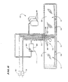
components of the centrifuge 30. The flexible tubing is ganged
together into an umbilicus 70 (see Figs. 4 to 6).
As Fig. 6 best shows, the non-rotating elements
attached to the umbilicus 70 include the second separation element
14, the phlebotomy needles 78 and 80 that provide vein access to
the donor, and the various containers 81 that provide or receive fluid
during processing.
More particularly, the umbilicus 70 connects the WB
inlet port 40 and the RBC collection port 42 of the rotating assembly
18 with stationary phlebotomy needles 78 and 80. One needle 78
continuously draws WB from the donor, while the other needle 80
continuously returns RBC to the donor. Alternatively, the system 10
could use a single phlebotomy needle to perform both functions in
sequential draw and return cycles using conventional techniques.
The umbilicus 70 also connects the PRP collection port
38 of the first chamber 24 with the LDPRP inlet port 46 of the
second chamber 26, via the second separation element 14, as Fig.
6 best shows. The second chamber 26 thereby receives LDPRP
through the umbilicus 70 from the first chamber 24 (via the second
separation element 14) for further separation into PPP and LDPC.
As Fig. 6 also shows, a portion of the PRP exiting the PRP
collection port 38 is diverted away from the second separation
element 14 for recirculation directly back to the WB inlet port 40.
The umbilicus 70 also conveys separated PPP from the
second chamber 26 through the associated PPP collection port 136.
A portion of PPP is conveyed by the umbilicus 70 to the donor
return needle 80. Another portion of PPP is conveyed by the
umbilicus to one or more of the collection containers 81 for
retention.
The LDPC remains behind in the second chamber 26
for later resuspension and collection, as will be described later.
As Fig. 5 shows, in operation, the centrifuge 30
suspends the rotor 28 in an upside down position during rotation,
compared to the position shown in Fig. 4.
As Fig. 5 also shows, a non-rotating (zero omega)
holder 72 holds the upper portion of the umbilicus 70 in a non-rotating
position above the rotor 28.
Another holder 74 rotates the mid-portion of the
umbilicus 70 at a first (one omega) speed about the rotor 28.
Another holder 76 (see Fig. 4) rotates the lower end of the umbilicus
70 next to the assembly 18 at a second speed twice the one omega
speed (the two omega speed), at which the rotor 28 also rotates.
This known relative rotation of the umbilicus 74 and rotor 28 keeps
the umbilicus 74 untwisted, in this way avoiding the need for rotating
seals.
The dimensions of the various regions created in the
processing chamber can, of course, vary according to the
processing objectives. Table 1 shows the various dimensions of a
representative embodiment of a
processing assembly 18 of the type
shown in Figs. 2 and 3. Dimensions A through F referenced in
Table 1 are identified in Figs. 2 and 3.
| Overall length (A): 49.5cm (19-1/2 inches) |
| Overall height (B): 7.1cm (2-13/16 inches) |
| First Stage Processing Chamber |
| Length (C): 25.7cm (10-1/8 inches) |
| Width (D): (6.0cm (2-3/8 inches) |
| Maximum Radial Depth in Use: 4 mm |
| Second Stage Processing Chamber |
| Length (E): 22.4cm (8-13/16 inches) |
| Width (F): 6.0cm (2-3/8 inches) |
| Maximum Radial Depth in Use: 4 mm |
| Port Spacing |
| (center line to center line): 1.0cm (3/8 inch) |
In this configuration, the RBC collection passage 56 and
the PPP collection passage 64 taper from a width of about 0.6cm
(1/4 inch) to 0.3cm (1/8 inch). The restricted passage 68 in the first
compartment 24 is about 1 mm to 2 mm in radial depth and about 1
mm to 2 mm in circumferential length.
In this configuration, when the rotor 28 is rotated at a
speed of about 3400 RPM, a centrifugal force field of about 900 G's
is generated along the high-G wall 34 of the chambers 24 and 26.
Alternatively, the system 10 can employ physically
separate processing chambers as the first and third elements 12
and 16. Such elements could then be usable in association with a
commercially available blood processing centrifuge, like the CS-3000®
Blood Separation Centrifuge made and sold by the Fenwal
Division of Baxter Healthcare Corporation (a wholly owned
subsidiary of the assignee of the present invention). These
alternative processing chambers are also disclosed in EP-A-0618831.
The system 10 carries out blood component separation
in the second element 14 using filtration.
The second element 14 comprises a filter device 82 that
employs a non-woven, fibrous filter media 84.
The composition of the filter media 84 can vary. In the
illustrated and preferred embodiment, the media 84 comprises fibers
that contain nonionic hydrophilic groups and nitrogen-containing
basic functional groups. Fibers of this type are disclosed in US-A-4,936,998.
Filter media 84 containing these fibers are commercially
sold by Asahi Medical Company in filters under the tradename
SEPACELL.
Filter media 84 containing these fibers have
demonstrated the capacity to remove leukocytes while holding down
the loss of platelets.
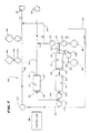
The system 10 shown in Figs. 1 to 6 can be readily
incorporated into a continuous single or double needle on line blood
processing systems. Fig. 7 shows in diagrammatic form a
representative continuous two needle on line processing system 86
that carries out an automated resuspended platelet collection
procedure employing the features of the invention.
A processing controller 88 operates the two needle
system 86 in continuous collection and return cycles, which occur
simultaneously. As used in this Specification, the terms
"continuous" and "simultaneous" are not meant to be limited to
sequences that are continuous or simultaneous only in the
quantitative sense. The terms are meant to encompass sequences
that, while not absolutely continuous or simultaneous quantitatively,
are "substantially" continuous or simultaneous in a qualitative sense,
when there is no significant operational or therapeutic difference in
terms of the way they operate and the function and result achieved.
In the collection cycle, the donor's WB is continuously
supplied through the draw needle 78 to the processing compartment
24 (for separation into RBC and PRP), while continuously conveying
PRP from the compartment 24 into the filter device 82 (for creating
LDPRP), and while continuously conveying LDPRP from the filter
device 82 into the compartment 26 (for separation into LDPC and
PPP).
During the return cycle, which in the two needle system
86 occurs simultaneously with the collection cycle, the controller 88
continuously returns RBC from the compartment 24 and a portion of
the PPP from the compartment 26 to the donor through the return
needle 80.
Throughout the processing period, the circulatory
system of the donor remains connected in communication with the
system 86 through the needles 78 and 80.
The controller 88 also continuously retains a portion of
the PPP exiting the compartment 26, diverting it from return to the
donor, during the entire period that LDPC is being separated in the
compartment 26. The system 86 retains the diverted PPP for long
term storage, as well as to aid processing and resuspension of
LDPC in the compartment 26 for long term storage as RES-LDPC.
The system 86 includes a container 90 that holds
anticoagulant. While the type of anticoagulant can vary, the
illustrated embodiment uses ACDA, which is a commonly used
anticoagulant for pheresis.
The system 86 also includes a container 92 that holds
saline solution for use in priming and purging air from the system 86
before processing begins.
The system 86 also includes one or more a collection
containers 94 for receiving RES-LDPC for therapeutic use, with or
without long term storage. The system 86 also includes one (or
optionally more) collection container 96 for retaining PPP during
processing. The container 96 ultimately can also serve as a long
term storage container for retained PPP.
Under the control of the controller 88, a first tubing
branch 98 and a WB inlet pumping station 100 direct WB from the
draw needle 78 to the WB inlet port 40 of the first stage processing
chamber 24. The WB inlet pumping station 100 operates
continuously at, for example, 50 ml/min. Meanwhile, an auxiliary
tubing branch 102 meters anticoagulant to the WB flow through an
anticoagulant pumping station 104.
ACDA anticoagulant can be added to constitute about
9% of the entry WB. Saline dilution fluid can also be added in an
amount representing about 4% of donor body volume (i.e., 200 ml
saline for 5000 ml in body volume).
Anticoagulated WB enters and fills the first processing
chamber 24 in the manner previously described. There, centrifugal
forces generated during rotation of the chamber assembly 18
separate WB into RBC and PRP.
The controller 88 operates a PRP pumping station 106
to draw PRP from the PRP collection port 38 into a second tubing
branch 108.
The processing controller 88 monitors the location of the
interface on the ramp 58. It varies the speed of the PRP pumping
station 106 to keep the interface at a prescribed location on the
ramp 58. The controller 88 also limits the maximum rate of the
variable PRP pumping station 106 (for example, 25 ml/min) to be
less than the WB inlet pumping station 100.
Meanwhile, a third tubing branch 110 conveys the RBC
from the RBC collection port 42 of the first stage processing
chamber 24. The third tubing branch 110 leads to the return needle
80 to return RBC to the donor.
The system 86 includes a recirculation tubing branch
112 and an associated recirculation pumping station 114. The
processing controller 88 operates the pumping station 114 to divert
a portion of the PRP exiting the PRP collection port 38 of the first
processing compartment 24 for remixing with the WB entering the
WB inlet port 94 of the first processing compartment 24.
The controller 88 can control the recirculation of PRP in
different ways.
In the illustrated and preferred embodiment, the
pumping rate of the
recirculation pump 114 is maintained as a
percentage (%
RE) of the pumping rate
WB inlet pump 100 governed
as follows:
%RE = K * Hct - 100
where:
When the pumping rate of the recirculation pump 114 is
maintained at the predetermined percentage (%RE) of the pumping
rate WB inlet pump 100, a surface hematocrit of about 30% to 35%
is maintained in the WB entry region of the first compartment 24.
The preferred surface hematocrit in the entry region is believed to
be about 32%.
Keeping the surface hematocrit in the entry region in the
desired range provides maximal separation of RBC and PRP.
The value of the dilution factor K can vary according to
operating conditions. The inventor has determined that K = 2.8,
when ACDA anticoagulant is added to constitute about 9% of the
entry whole blood volume, and a saline dilution fluid is added in an
amount representing about 4% of donor body volume (i.e., 200 ml
saline for 5000 ml in body volume).
By mixing PRP with the WB entering the first processing
compartment 24 to control surface hematocrit in the entry region,
the velocity at which RBC settle toward the high-G wall 66 in
response to centrifugal force increases. This, in turn, increases the
radial velocity at which plasma is displaced through the interface
toward the low-G wall 64. The increased plasma velocities through
the interface elute platelets from the interface. As a result, fewer
platelets settle on the interface.
The remainder of the PRP exiting the first compartment
24 enters the filter device 82 (by operation of the pumping station
106) for removal of leukocytes. A preferred flow rate of PRP
through the filter device 82 is in the range of 15 to 30 ml/minute.
The continuous on-line removal of leukocytes from PRP
that the invention provides does not activate platelets carried in the
PRP.
The concurrent recirculation of a portion of the PRP
away from the filter device 82 reduces the overall flow volume load
on the filter device 82. This, in turn, enhances the leukocyte
removal efficiencies of the filter device 82.
A fourth tubing branch 118 conveys LDPRP to the
LDPRP inlet port 46 of the second stage processing chamber 26.
There, LDPRP undergoes further separation into LDPC and PPP,
as earlier described.
PPP exits the PPP collection port 44 of the second
stage processing chamber 26 through a fifth tubing branch 120.
The fifth tubing branch 120 joins the third tubing branch 110
(carrying RBC), which leads to the return needle 80.
The system 86 includes a sixth tubing branch 122 and
an associated pumping station 124 for continuously retaining a
portion of the PPP during the entire processing period.
The processing controller 88 operates the PPP retaining
pumping station 124 throughout the period that separation occurs
within the compartment 26 to continuously divert a prescribed
portion of the PPP exiting the PPP collection port 44 away from the
third tubing branch 110. The sixth tubing branch 122 continuously
conveys the diverted PPP to the collection container 96 for
retention.
As before stated, the remainder of the PPP exiting the
second compartment 26 enters the third branch 110, where it joins
the RBC for return to the donor by operation of the PPP return pump
station 116.
The processing controller 88 controls the flow rate of the
pumping station 124 to retain the desired proportional volume of
PPP separated in the second chamber 26. The system 86 returns
the remaining PPP to the donor.
In the preferred embodiment, the controller 88
incorporates a PPP retention control process 132 (see Fig. 8) that
governs the rate at which PPP should be retained (expressed in
ml/min) during the processing period to collect the volume of PPP
desired by the end of the processing period. The control process
not only takes into account the physical operating parameters of the
system 86, but it also takes into account the physiology and comfort
of the individual donor.
As Fig. 8 shows, the control process 132 receives as
input the donor's weight; the donor's platelet count (before
donation); the desired platelet yield; and the targeted system
efficiency. The system efficiency is expressed as the percentage of
the platelets processed that are ultimately collected as LDPC.
Taking these parameters into consideration, the control
process 132 determines the total WB volume that should be
processed to obtain the desired platelet yield.
From the total WB volume, the control process 132
derives the total PPP volume. The plasma volume is derived by
multiplying the total WB volume by (1.0 - Hct), where Hct is
expressed in decimal form (e.g., 0.4 instead of 40%).
The control process 132 also receives as input the
amount of PPP the operator wants to retain during processing. The
control process 132 first compares the desired PPP retention
volume to the maximum volume of PPP that, under applicable
governmental regulations, can be retained. In the United States, for
example, the Food and Drug Administration limits the volume of
plasma that can be collected from a donor during a given procedure
to 600 ml for donors with a body weight less than 175 pounds, and
750 ml from a donor with a body weight equal to or greater than 175
pounds.
If the desired PPP retention volume does not exceed
the maximum allowable retention volume, the control process 132
subtracts the desired PPP volume from the total PPP volume to
derive the PPP return volume. Otherwise, the control process 132
generates an error signal, informing the user that less PPP must be
retained.
The control process 132 uses the donor's hematocrit
(Hct) and the selected anticoagulant ratio to set a WB flow rate the
donor should be able to tolerate. A look up table can be empirically
prepared to correlate WB flow rates with these factors.
Alternatively, the user can select a nominal WB flow
rate based upon experience (say, 50 to 60 ml/min). The user can
then make on line adjustments as necessary during processing
based upon the observed response of the donor.
Based upon the WB processing volume and the
selected anticoagulant ratio, the control process 132 determines the
volume of anticoagulant that will be mixed with WB during
processing.
The control process 132 adds together the total WB
processing volume and the total anticoagulant volume (plus any
dilution fluids, if added) to determine the total fluid volume that will
be processed. By dividing the total fluid volume by the WB flow
rate, the control process 132 calculates the total processing time.
Based dividing the desired PPP retention volume by the
derived processing time, the control process 132 derives the rate at
which the PPP retention pump 124 must be operated.
The control process 132 also determines the effect of
the PPP retention rate upon the rate at which the donor receives
citrate in the portion of PPP that is returned to the donor. The
control process adjusts the derived PPP retention rate as necessary
to avoid a citrate return rate that is higher than a preset,
physiologically relevant value.
Based upon the total volume of anticoagulant and the
type of the anticoagulant, the control process 132 determines the
total volume of citrate that will be mixed with WB.
The proportion of citrate contained in anticoagulants is
known. For example, ACDA anticoagulant contains 21.4 mg of
citrate for each ml of solution.
Based upon the proportion of PPP that will be returned
to the donor, the control process 132 derives the rate at which the
system will infuse the citrate into the donor. The control process
132 derives the citrate infusion rate in terms of the amount of citrate
(in mg) the donor receives with the returned PPP per unit of donor
body weight (in kg) per unit of processing time (in minutes).
The control process 132 compares the derived citrate
infusion rate to a nominal citrate infusion rate, which is also
expressed in mg citrate per kg body weight per minute of processing
time. The nominal citrate infusion rate represents a predetermined
maximum rate that citrate can be infused in a typical donor without
causing donor discomfort and other citrate-related reactions. The
control process 132 in the illustrated and preferred embodiment sets
the nominal citrate infusion rate at 1.2 mg/kg/min, which is based
upon empirical data.
As long as the targeted PPP retention rate results in a
citrate infusion rate that is equal to or less than 1.2 mg/kg/min, the
controller 88 is free to adjust the operating parameters of the system
86 as necessary to maximize the component yields and processing
efficiencies.
However, if a targeted PPP retention rate results in a
citrate infusion rate that exceeds 1.2 mh/kg/min, the controller 88
adjusts the processing parameters to lower the citrate infusion rate.
The control process 132 shown in Fig. 8 can be
expressed in various ways in terms of a series of simultaneous
equations that, when solved, derive the operating parameters listed
above. The equations can be solved recursively during processing
to take into account changes in Hct and platelet counts in the
donor's WB.
The continuous retention of PPP serves multiple
purposes, both during and after the component separation process.
The retention of PPP serves a therapeutic purpose
during processing. PPP contains most of the anticoagulant that is
metered into WB during the component separation process. By
retaining a portion of PPP instead of returning it all to the donor, the
overall volume of anticoagulant received by the donor during
processing is reduced. This reduction is particularly significant
when large blood volumes are processed.
By continuously diverting PPP away from the donor
throughout the separation process, the donor realizes this benefit
continuously throughout the processing period, provided that the
nominal citrate infusion rate is not exceeded. The monitoring
function that control process 132 performs assures that this benefit
will be obtained.
Also the retention of PPP during processing keeps the
donor's platelet count higher and more uniform during processing.
This is because the donor receives back less fluid volume during the
processing period, thereby reducing the dilution of whole blood
undergoing processing.
EXAMPLE 2
This Example demonstrates the results obtained by
operation of the control process 132 shown in Fig. 8 in connection
with a platelet collection procedure for a representative donor.
In this Example, the donor is assumed to have a body
weight of 125 lbs (56.3 kg). The donor is also assumed to have a
preprocessing Hct of 40% and a preprocessing platelet count of
250,000 per µl.
In this Example, the desired platelet yield for the
process is 4.0 x 10¹¹; and the desired system efficiency is 90%.
ACDA anticoagulant is used at a WB-to-anticoagulant ratio of 9%.
Based upon the above assumptions, the control
process derives 2.0 L as the total WB volume that must be
processed. The total volume of PPP associated with this WB
volume is 1200 ml.
Based upon the 9% anticoagulant ratio, the control
process 132 derives 180 ml as the volume of anticoagulant that will
be added. The total processing volume is therefore 2180 ml. The
total citrate amount is 3.852g.
The user sets 60 ml/min as the nominal WB inlet flow
rate. At this rate, the processing time will be 36.3 minutes.
The user seeks to ultimately retaining 500 ml of PPP
during processing, which is well short of the prescribed maximum for
the donor's body weight. With a processing time of 36.3 minutes,
the PPP retention pump must be operated at a rate of 13.8 ml/min
throughout the process to collect the desired PPP volume of 500 ml.
The remaining 700 ml will be returned to the donor.
This means that the donor will receive only about 58% (7/12th) of the
total anticoagulant volume that would have been received, if the
system 86 retained no PPP.
Moreover, when 500 ml of PPP is retained, the total
fluid volume returned to the donor is just 3/4 of the total drawn
volume. In a single needle system, each return cycle would take
less time and allow an overall higher blood flow rate.
The control process 132 derives the citrate infusion rate
by first determining the volume of citrate that the returned PPP will
carry, which is 22.47 ml (7/12th of 38.52 ml). The control process
132 then divides the returned citrate volume by the donor's body
weight (56.3 kg) and by the processing time (36.3 min) to obtain a
citrate return rate of 1.1 mg/kg/min.
The control process 132 determines that the citrate
return rate is less than the nominal 1.2 mg/kg/min. The PPP
retention pump 124 can thereby be operated at 13.8 ml/min without
anticipating adverse donor citrate-related reactions.
The system 86 also derives processing benefits from
the retained PPP.
The system 86 can, recirculate a portion of the retained
PPP, for mixing with WB entering the first compartment 24.
In this mode, the system 86 opens clamps C6 and C7 to
convey retained PPP from the container 96 through a PPP
recirculation branch 134 (see Fig. 7) and associated pumping
station 136 into the recirculation branch 112.
The controller 88 controls the pumping station 136 in
the same manner described for pumping station 114 to mix retained
PPP with the incoming WB entering the first compartment 24.
KEEP-OPEN MODE
Should WB flow be temporarily halted during
processing, the system 86 enters a "keep-open" mode. In this
mode, the system 86 draws upon the retained volume of PPP as an
anticoagulated "keep-open" fluid.
More particularly, the system controller 88 closes
clamps C1 and C2, opens clamp C3, and operates the pump 116 to
direct a volume of the PPP from the container 96 through a keep
open tubing branch 126, which communicates with the WB tubing
branch 98. The anticoagulant present in the PPP keeps the WB
tubing branch 98 open and patent until the flow of anticoagulated
WB resumes.
The system controller 88 keeps the return needle 80
open and patent by intermittently closing clamp C3 and opening
clamp C2 to provide a keep open flow of anticoagulated PPP
through the return needle 80.
Use of PPP as a keep-open fluid avoids the need to
introduce additional anticoagulant from container 90 for this
purpose.
RINSE-BACK MODE
The system 86 also enters a "rinse-back" mode at the
end of the separation process. In this mode, the system 86 draws
upon the retained volume of PPP as a "rinse-back" fluid.
More particularly, the system controller 88 stops the
flow of WB through the tubing branch 98 by closing clamp C4. The
system controller 88 closes the clamp C2, opens clamp C3, and
operates the pump 116 to direct a volume of the collected PPP into
the first separation compartment 24 through tubing branches 122,
120, 126 and 98. The flow of PPP resuspends and purges RBC
from the compartment 24 for return to the donor through the return
branch 110.
Because PPP, and not saline, is the rinse-back fluid,
downstream component separation through the filter device 82 and
the second compartment 26 can continue without interruption during
the rinse-back mode. The PPP volume used for rinse-back
purposes ultimately returns, after separation in the first compartment
24 and flow through the second compartment 26, to the source PPP
retention container 96.
RESUSPENSION MODE
The system 86 also operates in a resuspension mode to
draw upon a portion of the retained PPP to resuspend LDPC in the
second compartment 24 for transfer and storage as RES-LDPC in
the collection container(s) 94.
In this mode, the system controller 88 closes clamps
C2, C3, and C5, while opening clamp C1. The controller 88
operates the pump 124 to convey a volume of retained PPP through
the PPP collection port 44 into the second compartment 26. This
returned PPP volume mixes with and resuspends LDPC in the
second compartment 26.
Preferably, during the resuspension period, the
compartment 26 is not rotated at high speeds. Instead, as PPP is
conveyed into the second compartment 26, the rotor 28 slowly
oscillates the assembly 18 first in one rotational direction and then in
an opposite rotational direction. The oscillation creates constantly
changing acceleration or agitation forces that aid the mixing and
resuspension process within the second compartment 26.
Also, a substantial portion of the fluid volume residing
with the LDPC in the second compartment 26 is preferably drawn
away before introducing the resuspension volume of PPP. The
controller 88 operates the pump 124 to convey this residual fluid
volume from the second compartment 26 into the PPP retention
container 96.
In the illustrated and preferred embodiment, the second
chamber 26 contains about 40 ml of PPP at the end of the
processing period. About 20 ml of the residual fluid volume is
conveyed away before resuspending the LDPC.
The second compartment 26 is therefore about half
empty of residual fluid when the resuspension process begins. This
fluid-depleted condition concentrates the volume of LDPC to
intensify the acceleration forces generated when the compartment
26 is oscillated. This further enhance the mixing and resuspension
process.
In the illustrated and preferred embodiment, about 20 ml
of PPP is returned and used as a resuspension fluid. After a
predetermined mixing period, the system controller 88 closes clamp
C1, opens clamp C5, and operates the RES-LDPC pumping station
128. This conveys the RES-LDPC volume out the PPP collection
port 44 through a RES-LDPC collection tubing branch 130 into the
container(s) 94 for storage.
In a preferred implementation, the resuspension mode
constitutes a series of sequential resuspension batches. In each
batch, the residual fluid volume of the second compartment 26 is
depleted by about 20 ml, and the assembly 18 is oscillated, and a
prescribed aliquot of about 20 ml PPP is conveyed into it.
Following a set mixing period, a volume of LDPC that is
resuspended is conveyed out of the second compartment 26 and
into the container(s) 94. These sequential batches repeat, until all
the volume of LDPC is suspended and conveyed as RES-LDPC into
the collection container(s) 94.
At the end of the resuspension process, a resuspension
volume of PPP (typically about 200 ml) resides with the RES-LDPC
to serve as a storage medium. Typically, about 4.0 x 10¹¹ platelets
are suspended in this fluid volume.
The remaining volume of retained PPP is stored in the
container 96 for subsequent therapeutic use.
The system 86 thereby boosts the yield of usable
therapeutic components during a given collection procedure.
In a single needle collection system (not shown) that
embodies the features of the invention, a return cycle does not
occur simultaneously with a collection cycle. Instead, the single
system repeatedly toggles between a collection cycle and a return
cycle.
During a given collection cycle, WB is drawn through
the single needle, and the separated RBC and a portion of the
separated PPP are temporarily pooled in reservoirs. When a
preselected volume of RBC is pooled in this manner, the associated
controller switches to a return cycle. In the return cycle, the WB flow
from the donor is suspended, while the pooled RBC and PPP are
returned to the donor through the same single needle.
In a single needle system, processing can continue
uninterrupted through the compartment 24, filter device 82, and the
compartment 26 during a return cycle by collecting a quantity of WB
in a reservoir upstream of the compartment 24 during the collection
cycle. The single needle system then draws WB from the reservoir
for processing during a return cycle.
A single needle system also retains a portion of the PPP
exiting the compartment 26, diverting it from pooling and return to
the donor, during the entire period that LDPC is being separated in
the compartment 26. The retained PPP is used for the same
purposes in a single needle system as in a two needle system.
The chamber assembly 18, the associated containers,
and the interconnecting tubing branches associated with the system
can be made from conventional approved flexible medical grade
plastic materials, such as polyvinyl chloride plasticized with di-2-ethyl-hexylphthalate
(DEHP).
Preferable, the container(s) 94 intended to store the
resuspended LDPC, are made of polyolefin material (as disclosed in
Gajewski et al U.S. Patent 4,140,162) or a polyvinyl chloride
material plasticized with tri-2-ethylhexyl trimellitate (TEHTM). These
materials, when compared to DEHP-plasticized polyvinyl chloride
materials, have greater gas permeability that is beneficial for platelet
storage.
Various features of the inventions are set forth in the
following claims.