EP0882486A1 - Process for enriched combustion using solid electrolyte ionic conductor systems - Google Patents
Process for enriched combustion using solid electrolyte ionic conductor systems Download PDFInfo
- Publication number
- EP0882486A1 EP0882486A1 EP98110239A EP98110239A EP0882486A1 EP 0882486 A1 EP0882486 A1 EP 0882486A1 EP 98110239 A EP98110239 A EP 98110239A EP 98110239 A EP98110239 A EP 98110239A EP 0882486 A1 EP0882486 A1 EP 0882486A1
- Authority
- EP
- European Patent Office
- Prior art keywords
- gas stream
- oxygen
- ion transport
- permeate side
- combustion
- Prior art date
- Legal status (The legal status is an assumption and is not a legal conclusion. Google has not performed a legal analysis and makes no representation as to the accuracy of the status listed.)
- Granted
Links
Images


Classifications
-
- F—MECHANICAL ENGINEERING; LIGHTING; HEATING; WEAPONS; BLASTING
- F23—COMBUSTION APPARATUS; COMBUSTION PROCESSES
- F23L—SUPPLYING AIR OR NON-COMBUSTIBLE LIQUIDS OR GASES TO COMBUSTION APPARATUS IN GENERAL ; VALVES OR DAMPERS SPECIALLY ADAPTED FOR CONTROLLING AIR SUPPLY OR DRAUGHT IN COMBUSTION APPARATUS; INDUCING DRAUGHT IN COMBUSTION APPARATUS; TOPS FOR CHIMNEYS OR VENTILATING SHAFTS; TERMINALS FOR FLUES
- F23L7/00—Supplying non-combustible liquids or gases, other than air, to the fire, e.g. oxygen, steam
- F23L7/007—Supplying oxygen or oxygen-enriched air
-
- B—PERFORMING OPERATIONS; TRANSPORTING
- B01—PHYSICAL OR CHEMICAL PROCESSES OR APPARATUS IN GENERAL
- B01D—SEPARATION
- B01D53/00—Separation of gases or vapours; Recovering vapours of volatile solvents from gases; Chemical or biological purification of waste gases, e.g. engine exhaust gases, smoke, fumes, flue gases, aerosols
- B01D53/22—Separation of gases or vapours; Recovering vapours of volatile solvents from gases; Chemical or biological purification of waste gases, e.g. engine exhaust gases, smoke, fumes, flue gases, aerosols by diffusion
- B01D53/228—Separation of gases or vapours; Recovering vapours of volatile solvents from gases; Chemical or biological purification of waste gases, e.g. engine exhaust gases, smoke, fumes, flue gases, aerosols by diffusion characterised by specific membranes
-
- B—PERFORMING OPERATIONS; TRANSPORTING
- B01—PHYSICAL OR CHEMICAL PROCESSES OR APPARATUS IN GENERAL
- B01D—SEPARATION
- B01D53/00—Separation of gases or vapours; Recovering vapours of volatile solvents from gases; Chemical or biological purification of waste gases, e.g. engine exhaust gases, smoke, fumes, flue gases, aerosols
- B01D53/32—Separation of gases or vapours; Recovering vapours of volatile solvents from gases; Chemical or biological purification of waste gases, e.g. engine exhaust gases, smoke, fumes, flue gases, aerosols by electrical effects other than those provided for in group B01D61/00
- B01D53/326—Separation of gases or vapours; Recovering vapours of volatile solvents from gases; Chemical or biological purification of waste gases, e.g. engine exhaust gases, smoke, fumes, flue gases, aerosols by electrical effects other than those provided for in group B01D61/00 in electrochemical cells
-
- C—CHEMISTRY; METALLURGY
- C01—INORGANIC CHEMISTRY
- C01B—NON-METALLIC ELEMENTS; COMPOUNDS THEREOF; METALLOIDS OR COMPOUNDS THEREOF NOT COVERED BY SUBCLASS C01C
- C01B13/00—Oxygen; Ozone; Oxides or hydroxides in general
- C01B13/02—Preparation of oxygen
- C01B13/0229—Purification or separation processes
- C01B13/0248—Physical processing only
- C01B13/0251—Physical processing only by making use of membranes
-
- F—MECHANICAL ENGINEERING; LIGHTING; HEATING; WEAPONS; BLASTING
- F23—COMBUSTION APPARATUS; COMBUSTION PROCESSES
- F23M—CASINGS, LININGS, WALLS OR DOORS SPECIALLY ADAPTED FOR COMBUSTION CHAMBERS, e.g. FIREBRIDGES; DEVICES FOR DEFLECTING AIR, FLAMES OR COMBUSTION PRODUCTS IN COMBUSTION CHAMBERS; SAFETY ARRANGEMENTS SPECIALLY ADAPTED FOR COMBUSTION APPARATUS; DETAILS OF COMBUSTION CHAMBERS, NOT OTHERWISE PROVIDED FOR
- F23M5/00—Casings; Linings; Walls
- F23M5/08—Cooling thereof; Tube walls
- F23M5/085—Cooling thereof; Tube walls using air or other gas as the cooling medium
-
- C—CHEMISTRY; METALLURGY
- C01—INORGANIC CHEMISTRY
- C01B—NON-METALLIC ELEMENTS; COMPOUNDS THEREOF; METALLOIDS OR COMPOUNDS THEREOF NOT COVERED BY SUBCLASS C01C
- C01B2210/00—Purification or separation of specific gases
- C01B2210/0043—Impurity removed
- C01B2210/0046—Nitrogen
-
- F—MECHANICAL ENGINEERING; LIGHTING; HEATING; WEAPONS; BLASTING
- F23—COMBUSTION APPARATUS; COMBUSTION PROCESSES
- F23L—SUPPLYING AIR OR NON-COMBUSTIBLE LIQUIDS OR GASES TO COMBUSTION APPARATUS IN GENERAL ; VALVES OR DAMPERS SPECIALLY ADAPTED FOR CONTROLLING AIR SUPPLY OR DRAUGHT IN COMBUSTION APPARATUS; INDUCING DRAUGHT IN COMBUSTION APPARATUS; TOPS FOR CHIMNEYS OR VENTILATING SHAFTS; TERMINALS FOR FLUES
- F23L2900/00—Special arrangements for supplying or treating air or oxidant for combustion; Injecting inert gas, water or steam into the combustion chamber
- F23L2900/07001—Injecting synthetic air, i.e. a combustion supporting mixture made of pure oxygen and an inert gas, e.g. nitrogen or recycled fumes
-
- Y—GENERAL TAGGING OF NEW TECHNOLOGICAL DEVELOPMENTS; GENERAL TAGGING OF CROSS-SECTIONAL TECHNOLOGIES SPANNING OVER SEVERAL SECTIONS OF THE IPC; TECHNICAL SUBJECTS COVERED BY FORMER USPC CROSS-REFERENCE ART COLLECTIONS [XRACs] AND DIGESTS
- Y02—TECHNOLOGIES OR APPLICATIONS FOR MITIGATION OR ADAPTATION AGAINST CLIMATE CHANGE
- Y02E—REDUCTION OF GREENHOUSE GAS [GHG] EMISSIONS, RELATED TO ENERGY GENERATION, TRANSMISSION OR DISTRIBUTION
- Y02E20/00—Combustion technologies with mitigation potential
- Y02E20/32—Direct CO2 mitigation
-
- Y—GENERAL TAGGING OF NEW TECHNOLOGICAL DEVELOPMENTS; GENERAL TAGGING OF CROSS-SECTIONAL TECHNOLOGIES SPANNING OVER SEVERAL SECTIONS OF THE IPC; TECHNICAL SUBJECTS COVERED BY FORMER USPC CROSS-REFERENCE ART COLLECTIONS [XRACs] AND DIGESTS
- Y02—TECHNOLOGIES OR APPLICATIONS FOR MITIGATION OR ADAPTATION AGAINST CLIMATE CHANGE
- Y02E—REDUCTION OF GREENHOUSE GAS [GHG] EMISSIONS, RELATED TO ENERGY GENERATION, TRANSMISSION OR DISTRIBUTION
- Y02E20/00—Combustion technologies with mitigation potential
- Y02E20/34—Indirect CO2mitigation, i.e. by acting on non CO2directly related matters of the process, e.g. pre-heating or heat recovery
-
- Y—GENERAL TAGGING OF NEW TECHNOLOGICAL DEVELOPMENTS; GENERAL TAGGING OF CROSS-SECTIONAL TECHNOLOGIES SPANNING OVER SEVERAL SECTIONS OF THE IPC; TECHNICAL SUBJECTS COVERED BY FORMER USPC CROSS-REFERENCE ART COLLECTIONS [XRACs] AND DIGESTS
- Y02—TECHNOLOGIES OR APPLICATIONS FOR MITIGATION OR ADAPTATION AGAINST CLIMATE CHANGE
- Y02P—CLIMATE CHANGE MITIGATION TECHNOLOGIES IN THE PRODUCTION OR PROCESSING OF GOODS
- Y02P20/00—Technologies relating to chemical industry
- Y02P20/10—Process efficiency
- Y02P20/129—Energy recovery, e.g. by cogeneration, H2recovery or pressure recovery turbines
Definitions
- the invention relates to the integration of oxygen enhanced combustion with oxygen separation processes that employ solid electrolyte ionic conductor membranes, and more particularly, to the integration of these processes to improve the economic efficiency and pollution-related problems of combustion processes.
- Air is a mixture of gases which may contain varying amounts of water vapor and, at sea level, has the following approximate composition by volume: oxygen (20.9%), nitrogen (78%), argon (0.94%), with the balance consisting of other trace gases.
- An entirely different type of membrane can be made from certain inorganic oxides. These solid electrolyte membranes are made from inorganic oxides, typified by calcium- or yttrium-stabilized zirconium and analogous oxides having a fluorite or perovskite structure.
- Some of these solid oxides have the ability to conduct oxygen ions at elevated temperatures if a electric potential is applied across the membrane, that is, the are electrically-driven or ionic conductors only.
- Recent research has led to the development of solid oxides which have the ability to conduct oxygen ions at elevated temperatures if a chemical driving potential is applied.
- These pressure-driven ionic conductors or mixed conductors may be used as membranes for the extraction of oxygen from oxygen-containing gas streams if a sufficient partial oxygen pressure ratio is applied to provide the chemical driving potential. Since the selectivity of these materials for oxygen is infinite and oxygen fluxes generally several orders of magnitude higher than for conventional membranes can be obtained, attractive opportunities are created for the production of oxygen using these ion transport membranes.
- Combustion processes usually operate at high temperature and therefore there is the potential for efficiently integrating ion transport systems with oxygen enhanced combustion processes and the present invention involves novel schemes for the integration of ion transport systems with oxygen enhanced combustion processes.
- Literature related to ion transport conductor technology for use in separating oxygen from gas stream include:
- Hegarty U.S. Patent No. 4,545,787, entitled Process for Producing By-Product Oxygen from Turbine Power Generation , relates to a method of generating power from an compressed and heated air stream by removing oxygen from the air stream, combusting a portion of the resultant air stream with a fuel stream, combining the combustion effluent with another portion of the resultant air stream, and expanding the final combustion product though a turbine to generate power.
- Hegarty mentions the use of silver composite membranes and composite metal oxide solid electrolyte membranes for removing oxygen from the air stream.
- Kang et al. U.S. Patent No. 5,516,359, entitled Integrated High Temperature Method for Oxygen Production , relates to a process for separating oxygen from heated and compressed air using a solid electrolyte ionic conductor membrane where the nonpermeate product is heated further and passed through a turbine for power generation.
- Oxygen-enriched or enhanced combustion include the above-mentioned U.S. Dept. of Energy reports authored by H. Kobayashi and H. Kobayashi, J.G. Boyle, J.G. Keller, J.B. Patton and R.C. Jain, Technical and Economic Evaluation of Oxygen Enriched Combustion Systems for Industrial Furnace Applications , in Proceedings of the 1986 Symposium on Industrial Combustion Technologies, Chicago, IL, April 29-30, 1986 , ed. M.A. Lukasiewics, American Society for Metals, Metals Park, OH, which discusses the various technical and economic aspects of oxygen-enhanced combustion systems.
- Oxygen-enriched combustion has been commercially practiced using oxygen manufactured by either cryogenic distillation or noncryogenic processes such as pressure swing adsorption (PSA). All of these processes operate at or below 100C and therefore are difficult to thermally integrate with combustion processes.
- PSA pressure swing adsorption
- Solid electrolytes have mainly been used in fuel cells and sensors, and to experimentally produce small quantities of pure oxygen from air, taking advantage of the infinite selectivity for oxygen transport.
- Electrically-driven solid electrolyte membranes have also been used for removing traces of oxygen from inert gas streams, where the application of a sufficient voltage to the membrane can reduce the oxygen activity of the retentate gas stream to a very low value.
- Many of these materials did not have appreciable oxygen ion conductivity. Only recently have materials been synthesized that have sufficiently high oxygen ion conductivities so as to make the gas separation process economically viable. Commercial gas separation, purification, or enrichment processes based on these materials have yet to be developed. Also, methods for integrating oxygen separation with oxygen-enriched combustion have not been discussed in the prior art.
- the inventors are unaware of the prior disclosure of a process configuration for the integration of an ion transport based oxygen production system with OEC.
- the invention comprises a process for separating a feed gas stream containing elemental oxygen into an oxygen-enriched gas stream and an oxygen-depleted gas stream wherein the oxygen-enriched gas stream is used in a combustor, said process comprising the steps of (a) compressing the feed gas stream; (b) separating the oxygen from the compressed feed gas stream using an ion transport module including an ion transport membrane having a retentate side and a permeate side to separate a purified oxygen gas stream on the permeate side and correspondingly depleting the oxygen on the retentate side to produce the oxygen-depleted gas stream, the purified oxygen gas stream mixing with other gas components on the permeate side to form the oxygen-enriched gas stream; and (c) purging the permeate side of the ion transport membrane with at least a portion of a combustion product gas stream obtained from the combustion in the combustor of the gas stream exiting the permeate side of the ion transport module.
- the feed gas stream is air.
- the combustion product gas stream used to purge the permeate side of the ion transport membrane includes a reactive gas that reacts with the purified oxygen gas stream permeating through the ion transport membrane.
- the combustion product gas stream is cooled before it is used to purge the permeate side of the ion transport membrane.
- the gas stream exiting the permeate side of the ion transport module has an oxygen concentration of from about 10% to about 90%.
- the feed gas stream is compressed before it is fed into the ion transport module.
- the combustor is integrated with the ion transport module on the permeate side of the ion transport membrane.
- At least a portion of the combustion product gas stream is used in a downstream process and at least a portion of a downstream product gas stream from the downstream process may be used to purge the permeate side of the ion transport membrane.
- an oxygen-containing gas stream is added to at least a portion of a downstream product gas stream from the downstream process and the resultant gas stream is passed through an afterburner to burn any fuel that remains in the downstream product gas stream.
- both the combustor and the downstream process are integrated with the ion transport module on the permeate side of the ion transport membrane.
- the downstream process involves the oxidation of metals, the purification of metals by oxidizing impurities in the metals, or a blast furnace.
- the present invention discloses process configurations that enable the economically attractive integration of ion transport oxygen production with oxygen-enriched combustion (OEC). Although pressure-driven processes are preferred for the simplicity of their design, the concepts described here are applicable to systems utilizing either an ionic-conductor-only membrane having electrodes and an external circuit for electron return or a mixed conductor membrane.
- OEC oxygen-enriched combustion
- the essence of the current process configuration is an ion transport membrane that employs a solid oxygen ion conducting or mixed conducting membrane to separate oxygen from an oxygen-containing gas, typically, but not necessarily, air, and to utilize the oxygen separated in a downstream process including, but not limited to, oxygen-enriched combustion.
- an oxygen-depleted gas for example, waste gases from the combustion process or any downstream process
- purging greatly enhances the driving force across the ion transport membrane and effects a high oxygen flux and a lower membrane area requirement.
- Recirculation of the combustion exhaust gas is also beneficial because it provides a diluent stream that is important for controlling the temperature in the combustor and minimizing NO x formation (for example, from infiltrating nitrogen). Efficiency of this process could also be enhanced by adding fuel to the flue gas entering the oxygen separator. This further reduces the partial pressure oxygen on the permeate side, resulting in even higher oxygen fluxes in the ion transport separator.
- the ion transport module can also function as the combustor, thereby eliminating the need for a separate combustor, unless the application requires a gas stream exiting the combuster at a temperature above 1100°C, the maximum operating temperature of many current ion transport membranes.
- the heat necessary to maintain the temperature of the ion transport module within the operating range can come from a variety of sources known to those skilled in the art, including, for example, heat generated in an afterburner and recirculated hot combustion product gases, among others.
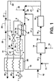
- Fig. 1 is a schematic diagram showing the integration of ion transport oxygen production with oxygen-enriched combustion.
- feed gas stream 1 containing elemental oxygen, usually air is compressed to a relatively low pressure in blower or compressor 2 to produce compressed feed gas stream 3 which is heated in heat exchanger 33 against waste gas stream 31 and product nitrogen gas stream 37 to produce warmed feed gas stream 4 .
- Gas stream 28 may be divided from warmed feed gas stream 4 and used in optional afterburner 26 to leave feed gas stream 5 which is optionally heated in heater 34 to produce hot feed gas stream 6 .
- Hot feed gas stream 6 then enters the feed side of ion transport module 35 employing ion transport membrane 7 having a retentate side 7a and a permeate side 7b .
- a portion of the oxygen in hot feed gas stream 6 is removed in ion transport module 35 and the exiting gas stream 8 becomes nitrogen-enriched with respect to feed gas stream 1 .
- the permeate side 7b of ion transport membrane 7 is purged using purge gas stream 9 containing products of combustion.
- Permeate gas stream 10 contains oxygen and this gas stream 10 is later mixed with fuel gas stream 11 .
- Air stream 12 can be optionally added to gas stream 10 .
- Combustible gas stream 13 after passing through an optional blower (not shown), then enters combustor 14 .
- fuel gas stream 15 can be fed directly to combustor 14 .
- the oxygen concentration in exhaust gas stream 16 can be maintained at low levels.
- exhaust gas stream 16 from combustor 14 is split into two portions, gas stream 17 and gas stream 18 .
- Gas stream 18 is used in downstream process 19 that requires heat input and the relatively cooler exhaust gas stream 20 from downstream process 19 may also be split into two portions, exhaust gas stream 21 and exhaust gas stream 22 .
- Fuel gas stream 25 may be added to exhaust gas stream 21 to produce gas stream 38 .
- Gas stream 38 can be added to gas stream 17 to produce gas stream 9 which enters ion transport module 35 and is used to purge the permeate side 17b of ion transport membrane 7 .
- gas stream 17 can be used to heat warmed feed gas stream 5 by heat exchange to produce hot feed gas stream 6 rather than using optional heater 34 .
- Exhaust gas stream 22 optionally fed into an optional afterburner 26 where air stream 27 or gas stream 28 are optionally added to produce hot waste gas stream 29 .
- Hot waste gas stream 29 may become gas stream 30 or gas stream 31 .
- gas stream 31 is used in heat exchanger 33 to heat compressed feed gas stream 3 to produce waste gas stream 32 .
- Gas stream 30 may be mixed with nitrogen-rich retentate gas stream 8 if nitrogen is not to be used as a co-product and if the temperature of exhaust gas stream 30 is adequately high.
- Retentate gas stream 8 is likely to be at a higher pressure than exhaust gas stream 30 and it may be necessary to release the excess pressure of retentate gas stream 8 using expansion valve 23 to produce retentate gas stream 34 before it is mixed with gas stream 30 . If retentate gas stream 24 is desired as a nitrogen-rich product gas stream, gas streams 36 and 30 are not mixed.
- Fuel gas streams 11 , 15 , and 25 can be introduced into the process configuration at any or all of the points shown in Fig. 1 to obtain the benefits of the invention; the use of at least one fuel gas stream is essential for the invention. For example, it may be desirable to add fuel gas stream 25 upstream of ion transport module 35 to greatly reduce the oxygen partial pressure on the permeate side 7b of ion transport membrane 7 . This would also result in some heat generation in ion transport module 35 due to fuel combustion, thereby offsetting some of the heating requirements of the oxygen transport process.
- the exiting nitrogen-rich gas stream 8 from ion transport module 35 could be made hotter. This would make the heat transfer in heat exchanger 33 more efficient, thereby reducing the area required for the heat exchange and potentially eliminating the need for heater 34 upstream of ion transport module 35 . If enough fuel can be combusted in ion transport module 35 on the purge or permeate side 7b of ion transport membrane 7 , it may altogether eliminate the need for a separate combustor 14 , that is, ion transport module 35 would also serve as the combustor (as described in Fig. 3). In such a situation, significant system simplification and cost reduction may result.
- Reactive purge arrangements are disclosed in "Reactive Purge for Solid Electrolyte Membrane Gas Separation", EP-A-0 778 069, filed December 4, 1996 and incorporated herein by reference.
- Preferred configuration for ion transport modules utilizing a reactive purge are disclosed in "Solid Electrolyte Ionic Conductor Reactor Design", EP Appln. No. 98 107 758.9 (Docket No. IG-20352-EP) filed April 28, 1998 and also incorporated herein by reference. Both applications are commonly owned with the present application.
- gas stream 17 is optionally used to purge the permeate side 7b of ion transport membrane 7 .
- hydrogen gas is a highly reducing gas with a higher reactivity than many other gaseous fuels, and its presence in ion transport module 35 will result in an extremely low oxygen partial pressure on the purge side 7b of ion transport membrane 7 and this will enable an even more rapid transport of oxygen through ion transport membrane 7 .
- afterburner 26 (perhaps catalytic) to which excess air 27 is added to burn off the carbon monoxide and hydrogen gas if their concentration is sufficiently high.
- Gas stream 28 of warmed feed gas stream 4 could also be added to afterburner 26 to provide for the afterburner requirements.
- Typical ranges for operating parameters of the ion transport module used in the invention are as follows.
- asymmetric or composite ion transport membranes that is, pressure-driven membranes
- the following properties are based on typical values reported in the literature for such membranes as could be used in the present invention.
- Standard mathematical models have been employed to determine to determine the operating conditions for the process shown in Fig. 1, that is, the membrane area requirement and the power and thermal energy inputs required at various points.
- This example modeling a process using a configuration of Fig. 1, is for illustrative purposes only and no attempt has been made to optimize the process configuration. The major reason why optimization is not attempted is that optimization is generally based on economic considerations and the commercial production of ion transport membrane systems is yet far from being mature, and no reliable cost estimates are presently available on such systems.
- fuel is added only to the process as fuel gas stream 11 .
- optional gas stream 17 is not considered, that is, gas streams 16 and 18 are identical.
- nitrogen is not sought as a co-product and retentate gas stream 36 , obtained from retentate gas stream 8 after reducing the excess pressure of the retentate using release valve 23 , is mixed with gas stream 30 , taken from exhaust gas stream 29 .
- it is not effective to lower the pressure of retentate gas stream 8 or to add gas stream 30 to retentate gas stream 8 upstream of heat exchanger 33 . Since exhaust gas stream 22 does not contain carbon monoxide and hydrogen gas, afterburner 26 is not installed.
- Fig. 2 is a schematic diagram similar to Fig. 1 showing a more efficient alternative using the catalytic afterburner installation.
- feed gas stream 41 containing elemental oxygen, usually air is compressed to a relatively low pressure in blower or compressor 42 to produce compressed feed gas stream 43 which is heated in heat exchanger 73 against hot waste gas stream 40 and product nitrogen gas stream 64 to produce warmed feed gas stream 44 .
- Gas stream 70 may be divided from warmed feed gas stream 44 and used in optional afterburner 69 to leave feed gas stream 74 which is optionally heated in heater 75 to produce hot feed gas stream 45 .
- Hot feed gas stream 45 then enters the feed side of ion transport module 46 employing ion transport membrane 47 having a retentate side 47a and a permeate side 47b . A portion of the oxygen in hot feed gas stream 45 is removed in ion transport module 46 and the exiting gas stream 48 becomes nitrogen-enriched with respect to feed gas stream 41 .
- Permeate gas stream 50 contains oxygen and this gas stream 50 is later mixed with fuel gas stream 51 .
- Air stream 52 can be optionally added to gas stream 50 .
- Combustible gas stream 53 after passing through an optional blower (not shown), then enters combustor 54 .
- fuel gas stream 55 can be fed directly to combustor 54 .
- Exhaust gas stream 56 from combustor 54 may be split into two portions, gas stream 57 and gas stream 58 .
- Gas stream 58 is used in downstream process 59 that requires heat input and the relatively cooler exhaust gas stream 60 from downstream process 59 may also be split into two portions, exhaust gas stream 61 and exhaust gas stream 62 .
- Fuel gas stream 65 may be added to exhaust gas stream 61 to produce gas stream 78 .
- Gas stream 78 can be added to gas stream 57 to produce gas stream 79 which enters ion transport module 46 and is used to purge the permeate side 47b of ion transport membrane 47 .
- Exhaust gas stream 62 may optionally be divided into two portions, hot waste gas stream 40 and gas stream 77 .
- hot waste gas stream 40 is used in heat exchanger 73 to heat compressed feed gas stream 43 to produce waste gas stream 74 .
- Gas stream 77 may be mixed with nitrogen-rich retentate gas stream 48 if nitrogen is not to be used as a co-product and if the temperature of exhaust gas stream 77 is adequately high. The reason for this step is to remove any unreacted fuel in exhaust gas stream 62 by combustion in afterburner 69 and to also generate heat energy to improve the efficiency of heat exchanger 73 .
- Retentate gas stream 48 is likely to be at a higher pressure than exhaust gas stream 77 and it may be necessary to release the excess pressure of retentate gas stream 48 using expansion valve 63 to produce retentate gas stream 76 before it is mixed with gas stream 77 to produce gas stream 80 .
- Gas stream 80 is fed into optional afterburner 69 where gas stream 70 is optionally added to produce hot waste gas stream 39 . In this case one would need to make sure that stream 80 contains enough oxygen for the combustion to proceed to completion. As mentioned above, gas stream 70 taken from warmed feed gas stream 44 can be optionally added to afterburner 69 to ensure this. It should be noted that the flow rate of the combined stream is increased by blending the exhaust gases from ion transport module 46 and downstream process 59 . This improves the capacity ratio in heat exchanger 73 and increases the heat transfer to compressed feed gas stream 43 . Product gas stream 64 will contain oxygen (used in excess to ensure complete combustion) and products of combustion if afterburner 69 is used and product gas stream 64 is generally discarded as a waste stream.
- Fuel gas streams 51 , 55 , and 65 can be introduced into the process configuration at any or all of the points shown in Fig. 2 to obtain the benefits of the invention and the use of at least one fuel gas stream is essential for the invention. As before, it may be desirable to add fuel gas stream 65 upstream of ion transport module 46 to greatly reduce the oxygen partial pressure on the permeate side 47b of ion transport membrane 47 .
- gas stream 57 is optionally used to purge the permeate side 47b of ion transport membrane 47 and the presence of hydrogen gas in ion transport module 46 will result in an extremely low oxygen partial pressure on the purge side 47b of ion transport membrane 47 and this will enable an even more rapid transport of oxygen through ion transport membrane 47 .
- the use of a fuel-rich feed to combuster 54 produces hydrogen gas as a part of the process cycle.
- afterburner 69 perhaps catalytic
- Fig. 3 is a schematic diagram showing another embodiment of the invention where the combustor is integrated with the ion transport module, that is, where the ion transport module itself serves as the combustor.
- feed gas stream 81 containing elemental oxygen, usually air is compressed to a relatively low pressure in blower or compressor 82 to produce compressed feed gas stream 83 which is heated in beat exchanger 113 against hot waste gas stream 116 and product nitrogen gas stream 93 to produce warmed feed gas stream 95 .
- Gas stream 110 may be divided from warmed feed gas stream 95 and used in optional afterburner 109 to leave feed gas stream 84 which is optionally heated in heater 114 to produce hot feed gas stream 85 .
- Hot feed gas stream 85 then enters the feed side of ion transport-combuster module 86 employing ion transport membrane 87 having a retentate side 87a and a permeate side 87b .
- a portion of the oxygen in hot feed gas stream 85 is removed in ion transport-combuster module 86 and the exiting gas stream 88 becomes nitrogen-enriched with respect to feed gas stream 81 .
- the permeate side 87b of ion transport membrane 87 is purged using purge gas stream 89 containing products of combustion and fuel.
- Permeate gas stream 90 contains oxygen and air stream 92 can be optionally added to gas stream 90 to produce gas stream 98 .
- the oxygen concentration in exhaust gas stream 90 can be maintained at low levels.
- Gas stream 98 is used in downstream process 99 that requires heat input and the relatively cooler exhaust gas stream 100 from downstream process 99 is also be split into two portions, exhaust gas stream 101 and exhaust gas stream 102 .
- Fuel gas stream 105 preferably is added to exhaust gas stream 101 to produce gas stream 89 which enters ion transport-combuster module 86 and is used to purge the permeate side 87b of ion transport membrane 87 .
- Exhaust gas stream 102 may optionally be divided into two portions, hot waste gas stream 116 and gas stream 115 .
- hot waste gas stream 116 is used in heat exchanger 113 to heat compressed feed gas stream 83 to produce waste gas stream 117 .
- Gas stream 115 may be mixed with nitrogen-rich retentate gas stream 88 if nitrogen is not to be used as a co-product and if the temperature of exhaust gas stream 115 is adequately high. The reason for this step is to remove any unreacted fuel in exhaust gas stream 102 by combustion in afterburner 109 and to also generate heat energy to improve the efficiency of heat exchanger 113 .
- Retentate gas stream 88 is likely to be at a higher pressure than exhaust gas stream 115 and it may be necessary to release the excess pressure of retentate gas stream 88 using expansion valve 103 to produce retentate gas stream 118 before it is mixed with gas stream 115 to produce gas stream 119 .
- Gas stream 119 is fed into optional afterburner 109 where gas stream 110 is optionally added to produce hot waste gas stream 93 . In this case one would need to make sure that stream 119 contains enough oxygen for the combustion to proceed to completion.
- gas stream 110 taken from warmed feed gas stream 95 can be optionally added to afterburner 109 to ensure this. It should be noted that the flow rate of the combined stream is increased by blending the exhaust gases from ion transport-combuster module 86 and downstream process 99 . This improves the capacity ratio in heat exchanger 113 and increases the heat transfer to compressed feed gas stream 83 .
- Gas stream 94 will contain oxygen (used in excess to ensure complete combustion) and products of combustion if afterburner 109 is used and gas stream 94 is generally discarded as a waste stream.
- ion transport membrane 87 may be formed as tubes with reactive purge gas stream 89 flowing inside the tubes. Owing to the heat generated on the purge side 87b of ion transport membrane 87 formed as tubes, the tubes will be at a high temperature and will act as heating elements. The ion transport membrane 87 tubes will radiate to the retentate side 87a or permeate side 87b where a process such as glass melting or metal annealing could be carried out.
- a part of the heat generated in ion transport module 86 could be used to preheat compressed feed gas stream 85 and purge gas stream 89 , possibly obviating the need for heat exchanger 113 and heater 114 .
- the furnace load will be placed on the permeate side 87b of ion transport membrane 87 (that is, the side with the oxidizing gas) in this case.
- ion transport-combuster module with an internal circulation of the flue (furnace) gas. If the furnace and the ion transport-combuster module operate at about the same temperature (for example, between 800°-1200°C), then the ion transport-combuster module can be placed directly inside the furnace provided that the furnace atmosphere is "clean", that is, it does not contain any species detrimental to the ion transport membrane.
- Fig. 4 One way of implementing this idea is shown in Fig. 4 in which the ion transport process, combuster, and downstream process are all integrated in a single unit. Feed stream 132 such as heated air is directed against cathode side 120a of membrane 120 to produce hot, oxygen-depleted retentate 134 such as nitrogen.
- Downstream process 130 (for example, a furnace load) is shown on the permeate or anode side 120b of ion transport membrane 120 .
- fuel gas stream 121 is fed close to the surface of permeate side 120b , thus sweeping away and/or efficiently consuming oxygen transported across ion transport membrane 120 .
- the combustion products in hot zone 138 could be recirculated in the furnace against anode side 120b by natural or forced convection; for the construction shown in Fig. 4, combustion products stream 146 , preferably obtained from furnace 130 as shown in phantom by stream 146a , and the fuel gas stream 121 are optionally fed through porous fuel distributor layer 122 adjacent to permeate side 120b of ion transport membrane 120 .
- distributor layer 122 defines at least one passage or chamber to more uniformly distribute fuel across the membrane 120 .
- Reacted permeate 136 containing oxygen and combustion products is directed to furnace 130 through hot zone 138 .
- a portion of hot nitrogen 140 is directed through valve 142 to provide an inerting atmosphere over the furnace 130 .
- Additional fuel 144 may be added to furnace 130 as desired.
- the ion transport membrane 120 is part of a separate module that is external to the furnace 130 .
- a two-stage ion transport system can be established in which the anode side of the first stage is purged by the retentate stream from the first stage to produce a diluted oxygen permeate stream while the anode side of the second stage is reactively purged to produce a fuel-rich permeate stream.
- the two permeate streams are used in a furnace for combustion with or without use of the hot nitrogen retentate streams in the furnace atmosphere.
- a furnace zone with the "right" temperature may be selected for ion transport operation (for example, preheat section of a continuous reheat furnace), or a special chamber with proper heat sinks to control the temperature can be created.
- the furnace heat loads that is, water or oil tubes
- a large amount of flue gas is circulated through this zone to continuously purge oxygen and keep the oxygen concentration low.
- Low oxygen concentration and high furnace gas circulation provide a synergy with the dilute oxygen combustion method.
- the oxygen for the OEC can be extracted from a low pressure feed gas stream by using the exhaust gas stream for purging and this should result in low power requirement for the oxygen separation process.
- the separate combustor unit can be eliminated. This would yield significant system simplification and cost savings.
- the nitrogen-rich stream retentate from the ion transport module can be used as a product. This may be most attractive if some fuel is added, for example, fuel gas stream 11 .
- nitrogen is desired as a co-product, it may be advantageous to compress the feed gas stream to the pressure required for product nitrogen supply.
- the retentate gas stream from the ion transport module may not be mixed with the exhaust gas stream from the downstream process. In this case, either a separate heat exchanger can be installed to recover heat from the exhaust gas stream, or no heat recovery may be attempted since generally exhaust gas stream will be much smaller and colder as compared to the retentate gas stream.
- the use of the purge gas stream decreases the oxygen concentration on the permeate side of the ion transport membrane.
- the reduced oxygen concentration makes the design of the ion transport module and of the downstream components (for example, combustor) on the purge side considerably easier from a materials standpoint.
- essentially pure oxygen would be produced on the permeate side of the ion transport membrane. Safe handling of such a high purity oxygen stream poses a significant challenge, especially at elevated temperature.
- the concentration of the oxygen in the purge exhaust can be easily controlled by a number of techniques: for example, varying the feed gas stream flowrate, varying the purge gas stream flowrate (increased recycle of the combustion products), changing the ion transport module operating temperature, or varying the membrane area of the ion transport stage. These techniques are also effective in controlling the total amount of oxygen separated and could be used for load tracking purposes.
- the use of the ion transport separator would eliminate the need for a stand-alone oxygen generator (for example, PSA) or an oxygen supply system (for example, liquid tank and vaporizer). This is expected to yield substantial reduction in capital cost and in the cost of the oxygen produced.
- a stand-alone oxygen generator for example, PSA
- an oxygen supply system for example, liquid tank and vaporizer
- solid electrolyte ionic conductor solid electrolyte
- ionic conductor ionic conductor
- ion transport membrane ion transport membrane
- nitrogen will usually mean oxygen-depleted gas, that is, oxygen-depleted relative to the feed gas.
- oxygen-depleted gas that is, oxygen-depleted relative to the feed gas.
- the ion transport membrane only allows oxygen permeation. Therefore, the composition of the retentate will depend on the composition of the feed gas.
- the feed gas will be depleted of oxygen but will retain nitrogen and any other gases (for example, argon) present in the feed gas.
- any other gases for example, argon
- elemental oxygen means any oxygen that is uncombined with any other element in the Periodic Table. While typically in diatomic form, elemental oxygen includes single oxygen atoms, triatomic ozone, and other forms uncombined with other elements.
- high purity refers to a product stream which contains less than five percent by volume of undesired gases.
- the product is at least 98.0% pure, more preferably 99.9% pure, and most preferably at least 99.99% pure, where "pure" indicates an absence of undesired gases.
- PSA Pressure-swing adsorption
- adsorption materials which are selective for a gas, typically nitrogen, to separate that gas from other gases.
- Such materials include rate-selective PSA materials, which are usually carbon-containing and provide high pressure nitrogen and low pressure oxygen, and equilibrium-selective PSA materials, which are usually lithium-containing and provide low pressure nitrogen and high pressure oxygen.
Abstract
Description


| Specifications of Important Gas Streams in the Integrated Process | ||||||||
| Gas Stream | Press. (psia) | Temp. (C) | Flow (100 SCFH) | Composition (mole %) | ||||
| O2 | N2 | CH4 | CO2 | H2O | ||||
| Feed 1 | 14.7 | 25 | 165.4 | 21 | 79 | - | - | - |
| Feed 6 to ion transport module | 20 | 800 | 165.4 | 21 | 79 | - | - | - |
| | 20 | 800 | 153.7 | 15 | 85 | - | - | - |
| | 15 | 800 | 82.7 | trace | - | - | 33.3 | 66.7 |
| | 15 | 800 | 94.4 | 12.4 | - | - | 29.2 | 58.4 |
| | 15 | 25 | 5.8 | - | - | 100 | - | - |
| Combustor input 13 | 15 | 745 | 100.2 | 11.7 | - | 5.8 | 27.5 | 55 |
| | 15 | 1,660 | 100.2 | trace | - | - | 33.3 | 66.7 |
| Downstream process exhaust 20 | 15 | 800 | 100.2 | trace | - | - | 33.3 | 66.7 |
| Waste 24 | 15 | 197 | 171.2 | 13.5 | 76.3 | - | 3.4 | 6.8 |
| Specifications for Key Modules in the Integrated Process | |
| | 49 |
| Feed blower or compressor 2 (efficiency = 75%) power (kW) | 58 |
| | 0.5 |
| Total amount of heat generated in combustor 14 (million BTU/hr) | 5.3 |
| Heat input requirement for downstream process 19 (million BTU/hr) | 5 |
Claims (10)
- A process for separating a feed gas stream containing elemental oxygen into an oxygen-enriched gas stream and an oxygen-depleted gas stream wherein the oxygen-enriched gas stream is used in a combustor, said process comprising:(a) compressing the feed gas stream;(b) separating the oxygen from the compressed feed gas stream using an ion transport module including an ion transport membrane having a retentate side and a permeate side to separate a purified oxygen gas stream on the permeate side and correspondingly depleting the oxygen on the retentate side to produce the oxygen-depleted gas stream, the purified oxygen gas stream mixing with other gas components on the permeate side to form the oxygen-enriched gas stream; and(c) purging the permeate side of the ion transport membrane with at least a portion of a combustion product gas stream obtained from the combustion in the combustor of the gas stream exiting the permeate side of the ion transport module.
- The process according to claim 1, wherein the feed gas stream is air.
- The process according to claim 1, wherein the combustion product gas stream used to purge the permeate side of the ion transport membrane includes a reactive gas that reacts with the purified oxygen gas stream permeating through the ion transport membrane.
- The process according to claim 1, further comprising:cooling the combustion product gas stream before it is used to purge the permeate side of the ion transport membrane.
- The process according to claim 1, wherein the gas stream exiting the permeate side of the ion transport module has an oxygen concentration of from about 10% to about 90%.
- The process according to claim 1, further comprising:heating the compressed feed gas stream before it is fed into the ion transport module.
- The process according to claim 1, wherein the combustor is integrated with the ion transport module on the permeate side of the ion transport membrane.
- The process according to claim 1, wherein at least a portion of the combustion product gas stream is used in a downstream process.
- The process according to claim 8, wherein both the combustor and the downstream process are integrated with the ion transport module on the permeate side of the ion transport membrane.
- The process according to claim 8, wherein at least a portion of a downstream product gas stream from the downstream process is used to purge the permeate side of the ion transport membrane.
Applications Claiming Priority (2)
| Application Number | Priority Date | Filing Date | Title |
|---|---|---|---|
| US868962 | 1997-06-05 | ||
| US08/868,962 US5888272A (en) | 1997-06-05 | 1997-06-05 | Process for enriched combustion using solid electrolyte ionic conductor systems |
Publications (2)
| Publication Number | Publication Date |
|---|---|
| EP0882486A1 true EP0882486A1 (en) | 1998-12-09 |
| EP0882486B1 EP0882486B1 (en) | 2005-03-02 |
Family
ID=25352647
Family Applications (1)
| Application Number | Title | Priority Date | Filing Date |
|---|---|---|---|
| EP98110239A Expired - Lifetime EP0882486B1 (en) | 1997-06-05 | 1998-06-04 | Process for enriched combustion using solid electrolyte ionic conductor systems |
Country Status (13)
| Country | Link |
|---|---|
| US (1) | US5888272A (en) |
| EP (1) | EP0882486B1 (en) |
| JP (1) | JPH10339405A (en) |
| KR (1) | KR100348019B1 (en) |
| CN (1) | CN1110348C (en) |
| BR (1) | BR9801784A (en) |
| CA (1) | CA2239677C (en) |
| DE (1) | DE69829132T2 (en) |
| ES (1) | ES2235274T3 (en) |
| ID (1) | ID20413A (en) |
| MY (1) | MY118555A (en) |
| RU (1) | RU2170388C2 (en) |
| ZA (1) | ZA984852B (en) |
Cited By (15)
| Publication number | Priority date | Publication date | Assignee | Title |
|---|---|---|---|---|
| WO2000033942A1 (en) * | 1998-12-04 | 2000-06-15 | Norsk Hydro Asa | Method for recovering co¿2? |
| EP1040861A1 (en) * | 1999-03-29 | 2000-10-04 | Praxair Technology, Inc. | Process for enriched combustion using solid electrolyte ionic conductor systems |
| EP1095691A2 (en) * | 1999-10-26 | 2001-05-02 | Praxair Technology, Inc. | Method and apparatus for producing carbon dioxide |
| WO2001079754A1 (en) * | 2000-04-19 | 2001-10-25 | Norsk Hydro Asa | Process for generation of heat and power and use thereof |
| EP1172135A1 (en) * | 2000-07-12 | 2002-01-16 | Praxair Technology, Inc. | Air separation method and system for producing oxygen to support combustion in a heat consuming device |
| EP1197257A1 (en) * | 2000-10-13 | 2002-04-17 | ALSTOM (Switzerland) Ltd | Process and apparatus for production of hot feed gas |
| EP1197256A1 (en) * | 2000-10-13 | 2002-04-17 | ALSTOM (Switzerland) Ltd | Process and apparatus for the production of hot combustion exhaust gas |
| WO2002053969A1 (en) * | 2000-12-29 | 2002-07-11 | Norsk Hydro Asa | A device for combustion of a carbon containing fuel in a nitrogen free atmosphere and a method for operating said device |
| WO2002059524A1 (en) * | 2001-01-23 | 2002-08-01 | Aker Technology As | A method and an apparatus for cycle fluid treatment in an oxygen fired semi-closed power cycle |
| US6499300B2 (en) | 2000-10-13 | 2002-12-31 | Alstom (Switzerland) Ltd | Method for operating a power plant |
| FR2838982A1 (en) * | 2002-04-26 | 2003-10-31 | Air Liquide | PROCESS FOR SUPPLYING COMPRESSED AIR TO AT LEAST ONE FIRST AND ONE SECOND USER POST |
| AT412706B (en) * | 2002-08-28 | 2005-06-27 | Axiom Angewandte Prozesstechni | METHOD FOR OBTAINING NITROGEN FROM AIR |
| EA008758B1 (en) * | 2003-11-17 | 2007-08-31 | Эр Продактс Энд Кемикалз, Инк. | Controlled heating and cooling of mixed conducting metal oxide materials |
| EP2281785A1 (en) * | 2009-08-06 | 2011-02-09 | AGC Glass Europe | Glass melting furnace |
| ES2770149A1 (en) * | 2018-12-31 | 2020-06-30 | Kerionics S L | GAS SEPARATION PROCEDURE IN AN OXICOMBUSTION PROCESS THROUGH THE USE OF PERMEABLE OXYGEN MEMBRANES (Machine-translation by Google Translate, not legally binding) |
Families Citing this family (46)
| Publication number | Priority date | Publication date | Assignee | Title |
|---|---|---|---|---|
| US6592782B2 (en) * | 1993-12-08 | 2003-07-15 | Eltron Research, Inc. | Materials and methods for the separation of oxygen from air |
| US5888273A (en) * | 1996-09-25 | 1999-03-30 | Buxbaum; Robert E. | High temperature gas purification system |
| NO308398B1 (en) * | 1997-06-06 | 2000-09-11 | Norsk Hydro As | Process for carrying out catalytic or non-catalytic processes in which oxygen is ± n of the reactants |
| US6059858A (en) * | 1997-10-30 | 2000-05-09 | The Boc Group, Inc. | High temperature adsorption process |
| US6368383B1 (en) * | 1999-06-08 | 2002-04-09 | Praxair Technology, Inc. | Method of separating oxygen with the use of composite ceramic membranes |
| US6521202B1 (en) * | 1999-06-28 | 2003-02-18 | University Of Chicago | Oxygen ion conducting materials |
| US6146549A (en) * | 1999-08-04 | 2000-11-14 | Eltron Research, Inc. | Ceramic membranes for catalytic membrane reactors with high ionic conductivities and low expansion properties |
| US6793711B1 (en) | 1999-12-07 | 2004-09-21 | Eltron Research, Inc. | Mixed conducting membrane for carbon dioxide separation and partial oxidation reactions |
| US6264811B1 (en) | 2000-03-21 | 2001-07-24 | Praxair Technology, Inc. | Ion conducting ceramic membrane and surface treatment |
| US6375913B1 (en) | 2000-04-10 | 2002-04-23 | Pranair Technology | Integration of ceramic membrane into a silicon oxide production plant |
| US7267804B2 (en) * | 2000-07-07 | 2007-09-11 | Buxbaum Robert E | Membrane reactor for gas extraction |
| US6539719B2 (en) | 2000-11-02 | 2003-04-01 | Praxair Technology, Inc. | Integration of ceramic oxygen transport membrane combustor with boiler furnace |
| US6562104B2 (en) | 2000-12-19 | 2003-05-13 | Praxair Technology, Inc. | Method and system for combusting a fuel |
| US6394043B1 (en) | 2000-12-19 | 2002-05-28 | Praxair Technology, Inc. | Oxygen separation and combustion apparatus and method |
| US6562105B2 (en) * | 2001-09-27 | 2003-05-13 | Praxair Technology, Inc. | Combined method of separating oxygen and generating power |
| CH695793A5 (en) * | 2001-10-01 | 2006-08-31 | Alstom Technology Ltd | Combustion method, in particular for methods of generation of electric power and / or heat. |
| US7303606B2 (en) * | 2002-01-08 | 2007-12-04 | The Boc Group, Inc. | Oxy-fuel combustion process |
| CN1298411C (en) * | 2002-01-08 | 2007-02-07 | 波克股份有限公司 | Fuel combustion method with oxygen |
| US20030138747A1 (en) | 2002-01-08 | 2003-07-24 | Yongxian Zeng | Oxy-fuel combustion process |
| US6702570B2 (en) | 2002-06-28 | 2004-03-09 | Praxair Technology Inc. | Firing method for a heat consuming device utilizing oxy-fuel combustion |
| US20040175663A1 (en) * | 2003-03-06 | 2004-09-09 | M. Shannon Melton | Method for combusting fuel in a fired heater |
| US7118612B2 (en) * | 2003-12-30 | 2006-10-10 | Praxair Technology, Inc. | Oxygen separation method utilizing an oxygen transport membrane reactor |
| FR2866695B1 (en) * | 2004-02-25 | 2006-05-05 | Alstom Technology Ltd | OXY-COMBUSTION BOILER WITH OXYGEN PRODUCTION |
| US7329306B1 (en) * | 2004-12-02 | 2008-02-12 | Uop Llc | Process for safe membrane operation |
| CN100361730C (en) * | 2005-01-14 | 2008-01-16 | 山东理工大学 | Ceramic hollow fiber membrane reactor for making oxygen by air separation, and its preparing method and use |
| US7427368B2 (en) * | 2005-08-16 | 2008-09-23 | Praxair Technology, Inc. | Synthesis gas and carbon dioxide generation method |
| SE529333C2 (en) * | 2005-11-23 | 2007-07-10 | Norsk Hydro As | The combustion installation |
| JP4714664B2 (en) * | 2006-10-31 | 2011-06-29 | 新日本製鐵株式会社 | Oxygen separator |
| US9651253B2 (en) * | 2007-05-15 | 2017-05-16 | Doosan Power Systems Americas, Llc | Combustion apparatus |
| US20090139497A1 (en) * | 2007-11-30 | 2009-06-04 | Bo Shi | Engine having thin film oxygen separation system |
| US7972415B2 (en) * | 2008-12-11 | 2011-07-05 | Spx Corporation | Membrane-based compressed air breathing system |
| US8999039B2 (en) | 2010-03-05 | 2015-04-07 | Koninklijke Philips N.V. | Oxygen separation membrane |
| EP2629880B1 (en) * | 2010-10-22 | 2017-04-05 | Koninklijke Philips N.V. | Arrangement and method for separating oxygen |
| US9199847B2 (en) * | 2011-03-03 | 2015-12-01 | Koninklijke Philips N.V. | Method and arrangement for generating oxygen |
| FI126249B (en) * | 2011-05-10 | 2016-08-31 | Aalto-Korkeakoulusäätiö | Combustion procedure and incinerator |
| US8820312B2 (en) * | 2011-12-06 | 2014-09-02 | King Fahd University Of Petroleum And Minerals | Oxygen transport reactor-based oven |
| US9772109B2 (en) * | 2012-07-18 | 2017-09-26 | Phillips 66 Company | Process for enabling carbon-capture from conventional steam methane reformer |
| KR101467034B1 (en) * | 2012-07-19 | 2014-12-02 | 한국기계연구원 | The high efficiency pure oxygen combustion system using the ion transport membrane and ejector |
| US10180253B2 (en) | 2012-10-31 | 2019-01-15 | Korea Institute Of Machinery & Materials | Integrated carbon dioxide conversion system for connecting oxyfuel combustion and catalytic conversion process |
| FR3015635B1 (en) * | 2013-12-23 | 2019-05-31 | L'air Liquide, Societe Anonyme Pour L'etude Et L'exploitation Des Procedes Georges Claude | INTEGRATED PROCESS FOR OXYCOMBUSTION AND OXYGEN PRODUCTION |
| US9797054B2 (en) | 2014-07-09 | 2017-10-24 | Carleton Life Support Systems Inc. | Pressure driven ceramic oxygen generation system with integrated manifold and tubes |
| US10337111B2 (en) * | 2015-12-15 | 2019-07-02 | Hamilton Sunstrand Corporation | Solid oxide electrochemical gas separator inerting system |
| US20180140996A1 (en) * | 2015-12-15 | 2018-05-24 | United Technologies Corporation | Solid oxide electrochemical gas separator inerting system |
| JP6851839B2 (en) * | 2017-01-27 | 2021-03-31 | 大陽日酸株式会社 | Heat recovery type oxygen nitrogen supply system |
| CN108905628B (en) * | 2018-06-29 | 2021-07-13 | 东南大学 | Control device based on direct oxygen enrichment of cellulose acetate membrane electrodialysis air |
| WO2023097166A1 (en) * | 2021-11-29 | 2023-06-01 | Via Separations, Inc. | Heat exchanger integration with membrane system for evaporator pre-concentration |
Citations (4)
| Publication number | Priority date | Publication date | Assignee | Title |
|---|---|---|---|---|
| US5160713A (en) * | 1990-10-09 | 1992-11-03 | The Standard Oil Company | Process for separating oxygen from an oxygen-containing gas by using a bi-containing mixed metal oxide membrane |
| US5306411A (en) * | 1989-05-25 | 1994-04-26 | The Standard Oil Company | Solid multi-component membranes, electrochemical reactor components, electrochemical reactors and use of membranes, reactor components, and reactor for oxidation reactions |
| EP0747108A2 (en) * | 1995-06-07 | 1996-12-11 | Air Products And Chemicals, Inc. | Oxygen production by ion transport membranes with work recovery |
| EP0778069A1 (en) * | 1995-12-05 | 1997-06-11 | Praxair Technology, Inc. | Reactive purge for solid electrolyte membrane gas separation |
Family Cites Families (20)
| Publication number | Priority date | Publication date | Assignee | Title |
|---|---|---|---|---|
| US4167457A (en) * | 1978-05-05 | 1979-09-11 | Giner, Inc. | Passive electrolytic separator |
| JPS60195880A (en) * | 1984-03-19 | 1985-10-04 | Hitachi Ltd | Power generation system using solid electrolyte fuel cell |
| US4545787A (en) * | 1984-07-30 | 1985-10-08 | Air Products And Chemicals, Inc. | Process for producing by-product oxygen from turbine power generation |
| JPH0286070A (en) * | 1988-06-14 | 1990-03-27 | Fuji Electric Co Ltd | Electrolyte concentration control system for liquid electrolyte type fuel cell |
| NO304808B1 (en) * | 1989-05-25 | 1999-02-15 | Standard Oil Co Ohio | Fixed multicomponent membrane, method of milling such a membrane and use thereof |
| US5354547A (en) * | 1989-11-14 | 1994-10-11 | Air Products And Chemicals, Inc. | Hydrogen recovery by adsorbent membranes |
| JPH03274674A (en) * | 1990-03-23 | 1991-12-05 | Mitsubishi Heavy Ind Ltd | Fuel cell power generation plant system |
| US5174866A (en) * | 1990-05-24 | 1992-12-29 | Air Products And Chemicals, Inc. | Oxygen recovery from turbine exhaust using solid electrolyte membrane |
| US5118395A (en) * | 1990-05-24 | 1992-06-02 | Air Products And Chemicals, Inc. | Oxygen recovery from turbine exhaust using solid electrolyte membrane |
| US5051113A (en) * | 1990-06-13 | 1991-09-24 | Du Pont Canada Inc. | Air-intake system for mobile engines |
| US5053059A (en) * | 1990-06-13 | 1991-10-01 | Du Pont Canada Inc. | Air-intake system for residential furnaces |
| US5169415A (en) * | 1990-08-31 | 1992-12-08 | Sundstrand Corporation | Method of generating oxygen from an air stream |
| US5205842A (en) * | 1992-02-13 | 1993-04-27 | Praxair Technology, Inc. | Two stage membrane dryer |
| US5516359A (en) * | 1993-12-17 | 1996-05-14 | Air Products And Chemicals, Inc. | Integrated high temperature method for oxygen production |
| US5435836A (en) * | 1993-12-23 | 1995-07-25 | Air Products And Chemicals, Inc. | Hydrogen recovery by adsorbent membranes |
| US5447555A (en) * | 1994-01-12 | 1995-09-05 | Air Products And Chemicals, Inc. | Oxygen production by staged mixed conductor membranes |
| US5547494A (en) * | 1995-03-22 | 1996-08-20 | Praxair Technology, Inc. | Staged electrolyte membrane |
| US5643354A (en) * | 1995-04-06 | 1997-07-01 | Air Products And Chemicals, Inc. | High temperature oxygen production for ironmaking processes |
| BR9601078A (en) * | 1995-05-18 | 1998-01-06 | Praxair Technology Inc | Process for removing oxygen from a feed stream to obtain an oxygen-depleted product stream |
| US5562754A (en) * | 1995-06-07 | 1996-10-08 | Air Products And Chemicals, Inc. | Production of oxygen by ion transport membranes with steam utilization |
-
1997
- 1997-06-05 US US08/868,962 patent/US5888272A/en not_active Expired - Fee Related
-
1998
- 1998-05-28 ID IDP980793A patent/ID20413A/en unknown
- 1998-06-03 KR KR10-1998-0020491A patent/KR100348019B1/en not_active IP Right Cessation
- 1998-06-04 RU RU98110636/06A patent/RU2170388C2/en active
- 1998-06-04 CA CA002239677A patent/CA2239677C/en not_active Expired - Fee Related
- 1998-06-04 ZA ZA984852A patent/ZA984852B/en unknown
- 1998-06-04 CN CN98103513A patent/CN1110348C/en not_active Expired - Fee Related
- 1998-06-04 ES ES98110239T patent/ES2235274T3/en not_active Expired - Lifetime
- 1998-06-04 EP EP98110239A patent/EP0882486B1/en not_active Expired - Lifetime
- 1998-06-04 JP JP10170499A patent/JPH10339405A/en active Pending
- 1998-06-04 DE DE69829132T patent/DE69829132T2/en not_active Expired - Fee Related
- 1998-06-04 MY MYPI98002509A patent/MY118555A/en unknown
- 1998-07-04 BR BR9801784A patent/BR9801784A/en not_active Application Discontinuation
Patent Citations (4)
| Publication number | Priority date | Publication date | Assignee | Title |
|---|---|---|---|---|
| US5306411A (en) * | 1989-05-25 | 1994-04-26 | The Standard Oil Company | Solid multi-component membranes, electrochemical reactor components, electrochemical reactors and use of membranes, reactor components, and reactor for oxidation reactions |
| US5160713A (en) * | 1990-10-09 | 1992-11-03 | The Standard Oil Company | Process for separating oxygen from an oxygen-containing gas by using a bi-containing mixed metal oxide membrane |
| EP0747108A2 (en) * | 1995-06-07 | 1996-12-11 | Air Products And Chemicals, Inc. | Oxygen production by ion transport membranes with work recovery |
| EP0778069A1 (en) * | 1995-12-05 | 1997-06-11 | Praxair Technology, Inc. | Reactive purge for solid electrolyte membrane gas separation |
Cited By (26)
| Publication number | Priority date | Publication date | Assignee | Title |
|---|---|---|---|---|
| WO2000033942A1 (en) * | 1998-12-04 | 2000-06-15 | Norsk Hydro Asa | Method for recovering co¿2? |
| US6767527B1 (en) | 1998-12-04 | 2004-07-27 | Norsk Hydro Asa | Method for recovering CO2 |
| EP1040861A1 (en) * | 1999-03-29 | 2000-10-04 | Praxair Technology, Inc. | Process for enriched combustion using solid electrolyte ionic conductor systems |
| EP1095691A3 (en) * | 1999-10-26 | 2003-05-14 | Praxair Technology, Inc. | Method and apparatus for producing carbon dioxide |
| EP1095691A2 (en) * | 1999-10-26 | 2001-05-02 | Praxair Technology, Inc. | Method and apparatus for producing carbon dioxide |
| WO2001079754A1 (en) * | 2000-04-19 | 2001-10-25 | Norsk Hydro Asa | Process for generation of heat and power and use thereof |
| KR100608440B1 (en) * | 2000-07-12 | 2006-08-02 | 프랙스에어 테크놀로지, 인코포레이티드 | Air separation method and system for producing oxygen to support combustion in a boiler |
| AU779829B2 (en) * | 2000-07-12 | 2005-02-10 | Praxair Technology, Inc. | Air separation method and system for producing oxygen to support combustion in a heat consuming device |
| EP1172135A1 (en) * | 2000-07-12 | 2002-01-16 | Praxair Technology, Inc. | Air separation method and system for producing oxygen to support combustion in a heat consuming device |
| EP1197257A1 (en) * | 2000-10-13 | 2002-04-17 | ALSTOM (Switzerland) Ltd | Process and apparatus for production of hot feed gas |
| US6497098B2 (en) | 2000-10-13 | 2002-12-24 | Alstom (Switzerland) Ltd | Method and device for generating hot combustion waste gases |
| US6510693B2 (en) | 2000-10-13 | 2003-01-28 | Alstom (Switzerland) Ltd | Method and device for producing hot working gases |
| EP1197256A1 (en) * | 2000-10-13 | 2002-04-17 | ALSTOM (Switzerland) Ltd | Process and apparatus for the production of hot combustion exhaust gas |
| US6499300B2 (en) | 2000-10-13 | 2002-12-31 | Alstom (Switzerland) Ltd | Method for operating a power plant |
| WO2002053969A1 (en) * | 2000-12-29 | 2002-07-11 | Norsk Hydro Asa | A device for combustion of a carbon containing fuel in a nitrogen free atmosphere and a method for operating said device |
| WO2002059524A1 (en) * | 2001-01-23 | 2002-08-01 | Aker Technology As | A method and an apparatus for cycle fluid treatment in an oxygen fired semi-closed power cycle |
| WO2003090904A1 (en) * | 2002-04-26 | 2003-11-06 | L'air Liquide, Societe Anonyme A Directoire Et Conseil De Surveillance Pour L'etude Et L'exploitation Des Procedes Georges Claude | Method of supplying compressed air to at least a first and a second user station |
| FR2838982A1 (en) * | 2002-04-26 | 2003-10-31 | Air Liquide | PROCESS FOR SUPPLYING COMPRESSED AIR TO AT LEAST ONE FIRST AND ONE SECOND USER POST |
| AT412706B (en) * | 2002-08-28 | 2005-06-27 | Axiom Angewandte Prozesstechni | METHOD FOR OBTAINING NITROGEN FROM AIR |
| EA008758B1 (en) * | 2003-11-17 | 2007-08-31 | Эр Продактс Энд Кемикалз, Инк. | Controlled heating and cooling of mixed conducting metal oxide materials |
| EP2281785A1 (en) * | 2009-08-06 | 2011-02-09 | AGC Glass Europe | Glass melting furnace |
| WO2011015618A1 (en) * | 2009-08-06 | 2011-02-10 | Agc Glass Europe | Furnace for melting glass |
| JP2013500930A (en) * | 2009-08-06 | 2013-01-10 | エージーシー グラス ユーロップ | Glass melting furnace |
| US9272937B2 (en) | 2009-08-06 | 2016-03-01 | Agc Glass Europe | Glass melting furnace |
| ES2770149A1 (en) * | 2018-12-31 | 2020-06-30 | Kerionics S L | GAS SEPARATION PROCEDURE IN AN OXICOMBUSTION PROCESS THROUGH THE USE OF PERMEABLE OXYGEN MEMBRANES (Machine-translation by Google Translate, not legally binding) |
| WO2020141246A1 (en) * | 2018-12-31 | 2020-07-09 | Kerionics, S.L. | Method for separating gases in an oxy-fuel combustion process by using oxygen-permeable membranes |
Also Published As
| Publication number | Publication date |
|---|---|
| RU2170388C2 (en) | 2001-07-10 |
| DE69829132T2 (en) | 2006-02-09 |
| BR9801784A (en) | 1999-08-03 |
| ES2235274T3 (en) | 2005-07-01 |
| ID20413A (en) | 1998-12-10 |
| CN1110348C (en) | 2003-06-04 |
| EP0882486B1 (en) | 2005-03-02 |
| MY118555A (en) | 2004-12-31 |
| KR19990006603A (en) | 1999-01-25 |
| KR100348019B1 (en) | 2004-05-27 |
| ZA984852B (en) | 1999-01-04 |
| AU6992098A (en) | 1998-12-10 |
| CN1220181A (en) | 1999-06-23 |
| CA2239677C (en) | 2002-02-12 |
| US5888272A (en) | 1999-03-30 |
| CA2239677A1 (en) | 1998-12-05 |
| JPH10339405A (en) | 1998-12-22 |
| DE69829132D1 (en) | 2005-04-07 |
| AU738862B2 (en) | 2001-09-27 |
Similar Documents
| Publication | Publication Date | Title |
|---|---|---|
| EP0882486A1 (en) | Process for enriched combustion using solid electrolyte ionic conductor systems | |
| EP1040861A1 (en) | Process for enriched combustion using solid electrolyte ionic conductor systems | |
| EP0778069B2 (en) | Reactive purge for solid electrolyte membrane gas separation | |
| CA2254128C (en) | Solid electrolyte ionic conductor systems for oxygen, nitrogen, and/or carbon dioxide production with gas turbine | |
| US5657624A (en) | Integrated production of oxygen and electric power | |
| US6537514B1 (en) | Method and apparatus for producing carbon dioxide | |
| MXPA96006096A (en) | Evacuation of reagents for separation of gases by solid membrane of electroli | |
| US5851266A (en) | Hybrid solid electrolyte ionic conductor systems for purifying inert gases | |
| WO2001079754A1 (en) | Process for generation of heat and power and use thereof | |
| MXPA98004444A (en) | Process for enriched combustion using electrolyte ionic conductor sol systems | |
| MXPA00003019A (en) | Process for enriched combustion using solid electrolyte ionic conductor systems | |
| MXPA98009619A (en) | Ionic solid electrolyte conductor systems for oxygen, nitrogen and / or carbon dioxide production with turbine |
Legal Events
| Date | Code | Title | Description |
|---|---|---|---|
| PUAI | Public reference made under article 153(3) epc to a published international application that has entered the european phase |
Free format text: ORIGINAL CODE: 0009012 |
|
| AK | Designated contracting states |
Kind code of ref document: A1 Designated state(s): DE ES FR GB NL |
|
| AX | Request for extension of the european patent |
Free format text: AL;LT;LV;MK;RO;SI |
|
| 17P | Request for examination filed |
Effective date: 19981217 |
|
| AKX | Designation fees paid |
Free format text: DE ES FR GB NL |
|
| 17Q | First examination report despatched |
Effective date: 20010611 |
|
| GRAP | Despatch of communication of intention to grant a patent |
Free format text: ORIGINAL CODE: EPIDOSNIGR1 |
|
| GRAS | Grant fee paid |
Free format text: ORIGINAL CODE: EPIDOSNIGR3 |
|
| GRAA | (expected) grant |
Free format text: ORIGINAL CODE: 0009210 |
|
| AK | Designated contracting states |
Kind code of ref document: B1 Designated state(s): DE ES FR GB NL |
|
| REG | Reference to a national code |
Ref country code: GB Ref legal event code: FG4D |
|
| REF | Corresponds to: |
Ref document number: 69829132 Country of ref document: DE Date of ref document: 20050407 Kind code of ref document: P |
|
| PGFP | Annual fee paid to national office [announced via postgrant information from national office to epo] |
Ref country code: NL Payment date: 20050516 Year of fee payment: 8 |
|
| PGFP | Annual fee paid to national office [announced via postgrant information from national office to epo] |
Ref country code: GB Payment date: 20050602 Year of fee payment: 8 |
|
| PGFP | Annual fee paid to national office [announced via postgrant information from national office to epo] |
Ref country code: FR Payment date: 20050617 Year of fee payment: 8 |
|
| PGFP | Annual fee paid to national office [announced via postgrant information from national office to epo] |
Ref country code: ES Payment date: 20050627 Year of fee payment: 8 |
|
| REG | Reference to a national code |
Ref country code: ES Ref legal event code: FG2A Ref document number: 2235274 Country of ref document: ES Kind code of ref document: T3 |
|
| PGFP | Annual fee paid to national office [announced via postgrant information from national office to epo] |
Ref country code: DE Payment date: 20050801 Year of fee payment: 8 |
|
| PLBE | No opposition filed within time limit |
Free format text: ORIGINAL CODE: 0009261 |
|
| STAA | Information on the status of an ep patent application or granted ep patent |
Free format text: STATUS: NO OPPOSITION FILED WITHIN TIME LIMIT |
|
| 26N | No opposition filed |
Effective date: 20051205 |
|
| ET | Fr: translation filed | ||
| PG25 | Lapsed in a contracting state [announced via postgrant information from national office to epo] |
Ref country code: GB Free format text: LAPSE BECAUSE OF NON-PAYMENT OF DUE FEES Effective date: 20060604 |
|
| PG25 | Lapsed in a contracting state [announced via postgrant information from national office to epo] |
Ref country code: ES Free format text: LAPSE BECAUSE OF NON-PAYMENT OF DUE FEES Effective date: 20060605 |
|
| PG25 | Lapsed in a contracting state [announced via postgrant information from national office to epo] |
Ref country code: NL Free format text: LAPSE BECAUSE OF NON-PAYMENT OF DUE FEES Effective date: 20070101 |
|
| PG25 | Lapsed in a contracting state [announced via postgrant information from national office to epo] |
Ref country code: DE Free format text: LAPSE BECAUSE OF NON-PAYMENT OF DUE FEES Effective date: 20070103 |
|
| GBPC | Gb: european patent ceased through non-payment of renewal fee |
Effective date: 20060604 |
|
| NLV4 | Nl: lapsed or anulled due to non-payment of the annual fee |
Effective date: 20070101 |
|
| REG | Reference to a national code |
Ref country code: FR Ref legal event code: ST Effective date: 20070228 |
|
| REG | Reference to a national code |
Ref country code: ES Ref legal event code: FD2A Effective date: 20060605 |
|
| PG25 | Lapsed in a contracting state [announced via postgrant information from national office to epo] |
Ref country code: FR Free format text: LAPSE BECAUSE OF NON-PAYMENT OF DUE FEES Effective date: 20060630 |