EP0884212A1 - Clutch adjustment determination - Google Patents
Clutch adjustment determination Download PDFInfo
- Publication number
- EP0884212A1 EP0884212A1 EP98304404A EP98304404A EP0884212A1 EP 0884212 A1 EP0884212 A1 EP 0884212A1 EP 98304404 A EP98304404 A EP 98304404A EP 98304404 A EP98304404 A EP 98304404A EP 0884212 A1 EP0884212 A1 EP 0884212A1
- Authority
- EP
- European Patent Office
- Prior art keywords
- master clutch
- input shaft
- engaged
- determining
- transmission
- Prior art date
- Legal status (The legal status is an assumption and is not a legal conclusion. Google has not performed a legal analysis and makes no representation as to the accuracy of the status listed.)
- Granted
Links
Images


Classifications
-
- B—PERFORMING OPERATIONS; TRANSPORTING
- B60—VEHICLES IN GENERAL
- B60W—CONJOINT CONTROL OF VEHICLE SUB-UNITS OF DIFFERENT TYPE OR DIFFERENT FUNCTION; CONTROL SYSTEMS SPECIALLY ADAPTED FOR HYBRID VEHICLES; ROAD VEHICLE DRIVE CONTROL SYSTEMS FOR PURPOSES NOT RELATED TO THE CONTROL OF A PARTICULAR SUB-UNIT
- B60W10/00—Conjoint control of vehicle sub-units of different type or different function
- B60W10/04—Conjoint control of vehicle sub-units of different type or different function including control of propulsion units
- B60W10/06—Conjoint control of vehicle sub-units of different type or different function including control of propulsion units including control of combustion engines
-
- B—PERFORMING OPERATIONS; TRANSPORTING
- B60—VEHICLES IN GENERAL
- B60W—CONJOINT CONTROL OF VEHICLE SUB-UNITS OF DIFFERENT TYPE OR DIFFERENT FUNCTION; CONTROL SYSTEMS SPECIALLY ADAPTED FOR HYBRID VEHICLES; ROAD VEHICLE DRIVE CONTROL SYSTEMS FOR PURPOSES NOT RELATED TO THE CONTROL OF A PARTICULAR SUB-UNIT
- B60W10/00—Conjoint control of vehicle sub-units of different type or different function
- B60W10/02—Conjoint control of vehicle sub-units of different type or different function including control of driveline clutches
-
- B—PERFORMING OPERATIONS; TRANSPORTING
- B60—VEHICLES IN GENERAL
- B60W—CONJOINT CONTROL OF VEHICLE SUB-UNITS OF DIFFERENT TYPE OR DIFFERENT FUNCTION; CONTROL SYSTEMS SPECIALLY ADAPTED FOR HYBRID VEHICLES; ROAD VEHICLE DRIVE CONTROL SYSTEMS FOR PURPOSES NOT RELATED TO THE CONTROL OF A PARTICULAR SUB-UNIT
- B60W10/00—Conjoint control of vehicle sub-units of different type or different function
- B60W10/10—Conjoint control of vehicle sub-units of different type or different function including control of change-speed gearings
- B60W10/11—Stepped gearings
-
- B—PERFORMING OPERATIONS; TRANSPORTING
- B60—VEHICLES IN GENERAL
- B60W—CONJOINT CONTROL OF VEHICLE SUB-UNITS OF DIFFERENT TYPE OR DIFFERENT FUNCTION; CONTROL SYSTEMS SPECIALLY ADAPTED FOR HYBRID VEHICLES; ROAD VEHICLE DRIVE CONTROL SYSTEMS FOR PURPOSES NOT RELATED TO THE CONTROL OF A PARTICULAR SUB-UNIT
- B60W30/00—Purposes of road vehicle drive control systems not related to the control of a particular sub-unit, e.g. of systems using conjoint control of vehicle sub-units, or advanced driver assistance systems for ensuring comfort, stability and safety or drive control systems for propelling or retarding the vehicle
- B60W30/18—Propelling the vehicle
- B60W30/1819—Propulsion control with control means using analogue circuits, relays or mechanical links
-
- B—PERFORMING OPERATIONS; TRANSPORTING
- B60—VEHICLES IN GENERAL
- B60W—CONJOINT CONTROL OF VEHICLE SUB-UNITS OF DIFFERENT TYPE OR DIFFERENT FUNCTION; CONTROL SYSTEMS SPECIALLY ADAPTED FOR HYBRID VEHICLES; ROAD VEHICLE DRIVE CONTROL SYSTEMS FOR PURPOSES NOT RELATED TO THE CONTROL OF A PARTICULAR SUB-UNIT
- B60W50/00—Details of control systems for road vehicle drive control not related to the control of a particular sub-unit, e.g. process diagnostic or vehicle driver interfaces
- B60W50/02—Ensuring safety in case of control system failures, e.g. by diagnosing, circumventing or fixing failures
- B60W50/0205—Diagnosing or detecting failures; Failure detection models
- B60W2050/021—Means for detecting failure or malfunction
-
- B—PERFORMING OPERATIONS; TRANSPORTING
- B60—VEHICLES IN GENERAL
- B60W—CONJOINT CONTROL OF VEHICLE SUB-UNITS OF DIFFERENT TYPE OR DIFFERENT FUNCTION; CONTROL SYSTEMS SPECIALLY ADAPTED FOR HYBRID VEHICLES; ROAD VEHICLE DRIVE CONTROL SYSTEMS FOR PURPOSES NOT RELATED TO THE CONTROL OF A PARTICULAR SUB-UNIT
- B60W2510/00—Input parameters relating to a particular sub-units
- B60W2510/02—Clutches
- B60W2510/0208—Clutch engagement state, e.g. engaged or disengaged
- B60W2510/0225—Clutch actuator position
-
- B—PERFORMING OPERATIONS; TRANSPORTING
- B60—VEHICLES IN GENERAL
- B60W—CONJOINT CONTROL OF VEHICLE SUB-UNITS OF DIFFERENT TYPE OR DIFFERENT FUNCTION; CONTROL SYSTEMS SPECIALLY ADAPTED FOR HYBRID VEHICLES; ROAD VEHICLE DRIVE CONTROL SYSTEMS FOR PURPOSES NOT RELATED TO THE CONTROL OF A PARTICULAR SUB-UNIT
- B60W2510/00—Input parameters relating to a particular sub-units
- B60W2510/06—Combustion engines, Gas turbines
- B60W2510/0638—Engine speed
-
- B—PERFORMING OPERATIONS; TRANSPORTING
- B60—VEHICLES IN GENERAL
- B60W—CONJOINT CONTROL OF VEHICLE SUB-UNITS OF DIFFERENT TYPE OR DIFFERENT FUNCTION; CONTROL SYSTEMS SPECIALLY ADAPTED FOR HYBRID VEHICLES; ROAD VEHICLE DRIVE CONTROL SYSTEMS FOR PURPOSES NOT RELATED TO THE CONTROL OF A PARTICULAR SUB-UNIT
- B60W2510/00—Input parameters relating to a particular sub-units
- B60W2510/10—Change speed gearings
- B60W2510/1005—Transmission ratio engaged
-
- B—PERFORMING OPERATIONS; TRANSPORTING
- B60—VEHICLES IN GENERAL
- B60W—CONJOINT CONTROL OF VEHICLE SUB-UNITS OF DIFFERENT TYPE OR DIFFERENT FUNCTION; CONTROL SYSTEMS SPECIALLY ADAPTED FOR HYBRID VEHICLES; ROAD VEHICLE DRIVE CONTROL SYSTEMS FOR PURPOSES NOT RELATED TO THE CONTROL OF A PARTICULAR SUB-UNIT
- B60W2510/00—Input parameters relating to a particular sub-units
- B60W2510/10—Change speed gearings
- B60W2510/1015—Input shaft speed, e.g. turbine speed
- B60W2510/102—Input speed change rate
-
- F—MECHANICAL ENGINEERING; LIGHTING; HEATING; WEAPONS; BLASTING
- F16—ENGINEERING ELEMENTS AND UNITS; GENERAL MEASURES FOR PRODUCING AND MAINTAINING EFFECTIVE FUNCTIONING OF MACHINES OR INSTALLATIONS; THERMAL INSULATION IN GENERAL
- F16H—GEARING
- F16H61/00—Control functions within control units of change-speed- or reversing-gearings for conveying rotary motion ; Control of exclusively fluid gearing, friction gearing, gearings with endless flexible members or other particular types of gearing
- F16H61/02—Control functions within control units of change-speed- or reversing-gearings for conveying rotary motion ; Control of exclusively fluid gearing, friction gearing, gearings with endless flexible members or other particular types of gearing characterised by the signals used
- F16H61/0202—Control functions within control units of change-speed- or reversing-gearings for conveying rotary motion ; Control of exclusively fluid gearing, friction gearing, gearings with endless flexible members or other particular types of gearing characterised by the signals used the signals being electric
- F16H61/0248—Control units where shifting is directly initiated by the driver, e.g. semi-automatic transmissions
-
- F—MECHANICAL ENGINEERING; LIGHTING; HEATING; WEAPONS; BLASTING
- F16—ENGINEERING ELEMENTS AND UNITS; GENERAL MEASURES FOR PRODUCING AND MAINTAINING EFFECTIVE FUNCTIONING OF MACHINES OR INSTALLATIONS; THERMAL INSULATION IN GENERAL
- F16H—GEARING
- F16H61/00—Control functions within control units of change-speed- or reversing-gearings for conveying rotary motion ; Control of exclusively fluid gearing, friction gearing, gearings with endless flexible members or other particular types of gearing
- F16H61/68—Control functions within control units of change-speed- or reversing-gearings for conveying rotary motion ; Control of exclusively fluid gearing, friction gearing, gearings with endless flexible members or other particular types of gearing specially adapted for stepped gearings
- F16H61/682—Control functions within control units of change-speed- or reversing-gearings for conveying rotary motion ; Control of exclusively fluid gearing, friction gearing, gearings with endless flexible members or other particular types of gearing specially adapted for stepped gearings with interruption of drive
-
- F—MECHANICAL ENGINEERING; LIGHTING; HEATING; WEAPONS; BLASTING
- F16—ENGINEERING ELEMENTS AND UNITS; GENERAL MEASURES FOR PRODUCING AND MAINTAINING EFFECTIVE FUNCTIONING OF MACHINES OR INSTALLATIONS; THERMAL INSULATION IN GENERAL
- F16H—GEARING
- F16H61/00—Control functions within control units of change-speed- or reversing-gearings for conveying rotary motion ; Control of exclusively fluid gearing, friction gearing, gearings with endless flexible members or other particular types of gearing
- F16H61/70—Control functions within control units of change-speed- or reversing-gearings for conveying rotary motion ; Control of exclusively fluid gearing, friction gearing, gearings with endless flexible members or other particular types of gearing specially adapted for change-speed gearing in group arrangement, i.e. with separate change-speed gear trains arranged in series, e.g. range or overdrive-type gearing arrangements
Definitions
- the present invention relates to a control method/system for sensing conditions indicative of a misadjusted master clutch in a fully or partially automated mechanical transmission system. Upon sensing the presence of such conditions, the vehicle operator will be notified, a maintenance request will be established and/or the vehicle drive line system will be operated in a fault-tolerant manner.
- a control system/method for sensing conditions deemed indicative of significant master clutch misadjustment in an automated mechanical transmission system. Upon sensing such conditions, the vehicle operator will be warned, a "maintenance required" record will be created and/or a clutch misadjustment tolerant mode of operation will be implemented.
- Fig. 1 is a schematic illustration, in block diagram format, of an automated vehicular transmission system utilizing the control of the present invention.
- Fig. 2 is a plan view of a combined range-and-splitter-type transmission.
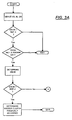
- Figs. 3A and 3B are schematic illustrations, in flow chart format, of the control system/method of the present invention.
- a vehicular automated mechanical transmission system 10 of the type advantageously utilizing the control method/system of the present invention is schematically illustrated in Fig. 1.
- the automated mechanical transmission system includes a fuel-controlled engine 12, such as a well-known diesel engine or the like, a master friction clutch 14 of the type described in U.S. Pat. No. 4,081,065, and a multiple-speed, change-gear mechanical transmission 16, which will be described in greater detail below.
- the engine includes a crankshaft 18 drivingly connected to the input members 14A of master clutch 14, which are selectively frictionally engaged with the output members 14B for driving the input shaft 20 of the transmission.
- the transmission includes an output shaft 22 which is drivingly associated with the vehicle drive wheels, as is well known in the prior art, whereby the rotational speed of the output shaft (OS) is indicative of vehicle speed.
- OS output shaft
- System 10 will also include a control unit 24, preferably a microprocessor-based control unit of the type illustrated in U.S. Pats. No. 4,595,986 and 5,335,566, for receiving input signals 26 and processing same according to predetermined logic rules to issue command output signals 28 to various system actuators and the like.
- a separate system controller 24 may be utilized, or the engine controller 30 associated with an electronically controlled engine and communicating over an electronic data link, such as a data link conforming to SAE J-1939, may be utilized.
- the control unit 24 will receive input signals from various sensors including a sensor 32 for providing a signal (ES) indicative of engine rotational speed, a sensor 34 for providing a signal (IS) indicative of transmission input shaft rotational speed, a sensor 36 for providing a signal indicative of output shaft rotational speed, a sensor 40 associated with the driver control console, and a sensor 42 for providing a signal (THL) indicative of the operator's displacement of the vehicle throttle pedal.
- the system 10 may include various actuators responsive to command output signals from the controller 24, each of which also may provide input signals of a monitored condition to controller 24.
- actuators include the engine controller 30 for controlling fueling of the engine to provide a desired engine speed and/or engine torque, a clutch actuator 44 for selectively engaging and disengaging master friction clutch 14, a transmission actuator 46 for selectively shifting transmission 16, and a display device 48 for providing information such as engaged gear ratio, system faults and the like, to the vehicle operator.
- the system is provided with an input shaft brake 50, also called a clutch brake or an upshift brake, for retarding the speed of the input shaft during upshifts. If an upshift brake is utilized, an upshift brake actuator 52 will be provided, which preferably is responsive to command output signals from controller 24 and also may provide signals indicative of the operational state of the input shaft brake 52 to the controller 24.
- Input shaft brakes are of many types, illustrations of which may be seen by reference to U.S. Patents No. 5,452,799 and 5,456,344.
- the ECU 24 also may be provided with memory means for storing operational information relative to system 10, including information as to elements requiring immediate maintenance attention, which may be accessed by means of a plug 54, by a handheld diagnostic tool or the like.
- engine 12 will be electronically controlled, including an electronic controller 30 communicating over an electronic data link (DL) operating under an industry standard protocol such as SAE J-1922, SAE J-1939, ISO 11898 or the like.
- DL electronic data link
- SAE J-1922, SAE J-1939, ISO 11898 or the like As is known, engine speed, throttle position, engine torque and other parameters may be sent over or read from the data link.
- Transmission 16 may be of any known transmission construction, examples of which may be seen by reference to U.S. Pats. No. 3,105,395; 3,335,616; 4,754,665 and 5,390,561.
- a typical multiple-speed, combined range-and-splitter-type compound transmission 16 may be seen by reference to Fig. 2.
- Transmission 16 comprises a main transmission section 112 connected in series with an auxiliary transmission section 114 having both range- and splitter-type gearing.
- input shaft 20 of transmission 16 is driven by the vehicle engine 12 through the selectively engaged and disengaged master clutch 14.
- input shaft 20 is rotatably fixed to the output members or plates 14B of master clutch 14.
- the input shaft 20 carries an input gear 120 for driving one or more countershaft assemblies 122.
- Each of the main section countershaft assemblies comprises a main section countershaft 124 supported by bearings in a housing 116 and is provided with main section countershaft gears 130, 132, 134, 136 and 138 fixed thereto.
- a plurality of main section drive or main shaft gears 140, 142 and 144 surround the transmission main shaft 146 and are selectively clutchable, one at a time, to the main shaft 146 for rotation therewith by sliding clutch collars 148 and 150, as is well known in the prior art.
- Clutch collars 148 and 150 in the preferred embodiment, are of the well-known, non-synchronized, double-acting jaw clutch type.
- Main section main shaft gear 144 is the reverse gear and is continuous meshing engagement with countershaft gears 138 by means of conventional intermediate idler gears (not shown).
- Auxiliary transmission section 114 is connected in series with main transmission section 112 and is of the 3-layer, 4-speed combined splitter/range type, as illustrated in aformentioned U.S. Pats. No. 4,754,665 and 5,390,561.
- Main shaft 146 extends into the auxiliary section 114 and is journalled in the inward end of the output shaft 22, which extends from the rearward end of the transmission.
- auxiliary transmission section 114 includes a plurality of substantially identical auxiliary countershaft assemblies (not shown), each comprising an auxiliary countershaft carrying three auxiliary section countershaft gears fixed for rotation therewith.
- the auxiliary countershaft gears are constantly meshed with and support auxiliary section splitter gear 174, splitter/range gear 176 and range gear 178.
- a sliding double-sided jaw collar 180 is utilized to selectively couple either the splitter gear 174 or the splitter/range gear 176 to the main shaft 146, while a 2-position synchronized clutch assembly 182 is utilized to selectively couple the splitter/range gear 176 or the range gear 178 to the output shaft 22.
- auxiliary transmission section 114 is a 3-layer auxiliary section of the combined splitter-and-range type, providing four selectable speeds or drive ratios between the input (main shaft 146) and the output (output shaft 22) thereof.
- the main section 112 provides a reverse and three potentially selectable forward speeds. However, one of the selectable main section forward gear ratios, the low speed gear ratios associated with the main shaft gear 142, is not utilized in the high range.
- transmission 16 is properly designated as a 10-speed "(2 + 1) x (2) x (2)" type transmission providing ten selectable forward speeds.
- clutch 182 the range clutch, should be a synchronized clutch, the double-acting clutch collar 80, the splitter clutch, is not required to be synchronized.
- a misadjusted clutch even when "disengaged", may have significant residual drag between the input 14A and output 14B friction members such that disengagement of a currently engaged gear ratio to initiate a shift into a different target gear ratio may require excessive force, the time required to achieve synchronous conditions for an upshift may become excessively long, excessive wear of the input shaft brake may occur and/or engagement of a target ratio, especially at start-from-stop conditions, may become difficult or impossible.
- control logic is provided whereby the system controller can sense an existing or impending excessive clutch misadjustment condition and, in response thereto, can notify the operator, take corrective action, create a record that clutch maintenance is required and/or modify system operational logic in a clutch misadjustment tolerant manner.
- master clutch disengagement can be determined or assumed in a variety of ways. If the system is equipped with engine speed (ES) and input shaft speed (IS) information, master clutch disengagement may be assumed whenever the difference between engine speed and input shaft speed exceeds a predetermined level (the absolute value of ES minus IS is greater than a reference (about 100 RPM)). If the system is provided with a clutch actuator controlled by the system ECU, master clutch disengagement may be assumed whenever the ECU has commanded the clutch actuator to disengage the master clutch.
- ES engine speed
- IS input shaft speed
- master clutch disengagement may be assumed whenever the difference between engine speed and input shaft speed exceeds a predetermined level (the absolute value of ES minus IS is greater than a reference (about 100 RPM)). If the system is provided with a clutch actuator controlled by the system ECU, master clutch disengagement may be assumed whenever the ECU has commanded the clutch actuator to disengage the master clutch.
- master clutch disengagement may be surmised whenever the input shaft speed falls below a predetermined value, which value preferably is below the idle speed of the engine. For heavy-duty diesel engines, input shaft speed below 400-500 RPM is considered indicative of master clutch disengagement.
- the state of master clutch adjustment may be determined based upon the deceleration rate of the input shaft over a predetermined time interval, such as, for example, .25 to 1.0 seconds. If the input shaft has a relatively low deceleration rate, i.e. , If dIS/dt is greater than a reference, this may be taken as a condition indicative of master clutch misadjustment. Of course, the rate of input shaft deceleration may be compared to various reference values to determine the degree of misadjustment ranging from a properly adjusted clutch, to a clutch requiring maintenance, to a clutch so misadjusted that vehicle operation in a normal manner is not possible.
- a vehicle display 48 may be caused to indicate to the driver that clutch adjustment is required and/or the system memory may be marked that clutch adjustment is required, which information may be derived from a handheld diagnostic tool accessing the controller through plug 54, or by other methods.
- the system may adopt a clutch misadjustment tolerant logic, such as, for example, causing the input shaft brake 50 to be applied in a delayed manner or at a lower input shaft speed to prevent undue wear on the input shaft brake.
- input shaft brake actuation may be prevented until a predetermined time (1-5 seconds) after IS falls below a reference value (about 400-600 RPM).
- the change in IS over a time period may be taken and compared to reference values. For example, assuming a 0.5-second time period is utilized, a change (IS INITIAL - IS FINAL ) of at least 150 RPM would be considered indicative of proper clutch adjustment, a change of 75-149 RPM would be considered an indication that adjustment is deteriorating but normal drive train operation is possible, and a change of less than 75 RPM would be considered an indication that the clutch is sufficiently misadjusted so as to require that a clutch-misadjustment-tolerant mode of operation be adopted.
- a change (IS INITIAL - IS FINAL ) of at least 150 RPM would be considered indicative of proper clutch adjustment
- a change of 75-149 RPM would be considered an indication that adjustment is deteriorating but normal drive train operation is possible
- a change of less than 75 RPM would be considered an indication that the clutch is sufficiently misadjusted so as to require that a clutch-misadjustment-tolerant mode of operation be adopted.
- the foregoing clutch adjustment evaluation may be performed every time it is determined that the master clutch and the transmission are disengaged or may be performed on a predetermined schedule.
Landscapes
- Engineering & Computer Science (AREA)
- Chemical & Material Sciences (AREA)
- Combustion & Propulsion (AREA)
- Transportation (AREA)
- Mechanical Engineering (AREA)
- Automation & Control Theory (AREA)
- Control Of Transmission Device (AREA)
- Hydraulic Clutches, Magnetic Clutches, Fluid Clutches, And Fluid Joints (AREA)
- Arrangement And Mounting Of Devices That Control Transmission Of Motive Force (AREA)
- Control Of Driving Devices And Active Controlling Of Vehicle (AREA)
Abstract
Description
Claims (27)
- A control system for a vehicular automated mechanical transmission system comprising a fuel-controlled engine having an engine output shaft, a mechanical change-gear transmission having an input shaft driven by said engine output shaft through a selectively engaged and disengaged master friction clutch, sensors for providing input signals indicative of system operating conditions, including signals indicative of the rotational speed of said transmission input shaft and of the engaged or disengaged condition of said transmission, and a controller for receiving said input signals and for processing same according to predetermined logic rules to make decisions and to issue command output signals, said control characterized by:means for determining an engaged or disengaged condition of said master clutch;means for determining an engaged or disengaged condition of said transmission;means for determining a test value indicative of the rate of change with respect to time of the rotational speed of said input shaft;means effective, upon determining master clutch and transmission disengaged conditions, to compare said test value to one or more predetermined first reference values to determine the state of adjustment of said master clutch; andmeans effective, upon determining the existence of an unsatisfactory state of adjustment of said master clutch, to initiate predetermined corrective action.
- The control of claim 1 wherein said input signals further include a signal indicative of engine rotational speed and said means for determining the engaged or disengaged condition of said master clutch makes said determination as a function of the difference between said engine speed and said input shaft speed.
- The control of claim 1 wherein said transmission system includes a master clutch actuation member and said input signals include a signal indicative of the position of said master clutch actuator, said means for determining the engaged or disengaged condition of said master clutch making said determination as a function of said signal indicative of the position of said actuator.
- The control of claim 1 wherein said means for determining the engaged or disengaged condition of said master clutch makes said determination as a function of the value of input shaft speed and a predetermined second reference value.
- The control of claim 4 wherein said predetermined second reference value is less than the expected idle speed of said engine.
- The control of claim 1 wherein said automated mechanical transmission system includes an input shaft brake and said input shaft brake is operated as a function of the determined state of adjustment of said master clutch.
- The control of claim 6 wherein said corrective action comprises preventing actuation of said input shaft brake until sensed input shaft speed is less than a predetermined third reference value.
- The control of claim 1 wherein said automated mechanical transmission system includes an operator display device and said corrrective action comprises notifying a vehicle operator of said master clutch misadjustment condition.
- The control of claim 1 wherein said automated transmission control unit controller includes a memory means for storing information relative to the operation of said system and said corrective action includes storing in said memory information relative to the determined state of misadjustment of said master clutch.
- A machine (24) for controlling a vehicular automated mechanical transmission system comprising a fuel-controlled engine (10) having an engine output shaft (18), a mechanical change-gear transmission (16) having an input shaft (20) driven by said engine through a selectively engaged and disengaged master friction clutch (14) and sensors (32, 34, 36, 40, 42) for providing input signals (26) indicative of system operating conditions, said machine comprising:(1) input signal receiving means for receiving said input signals, including input signals (IS) indicative of input shaft rotational speed and of the engaged ratio or neutral condition of said transmission (GR); and(2) data processing means for processing said input signals according to predetermined logic rules to make decisions and to issue command output signals (28) to system actuators (46, 48), said data processing means including logic rules for:(a) determining an engaged or disengaged condition of said master clutch;(b) determining an engaged or neutral condition state of said transmission;(c) determining a test value indicative of rate of change with respect to time of said input signal indicative of the rotational speed of said transmission input shaft;(d) upon determining master clutch and transmission disengaged conditions, comparing said test value to a predetermined first reference value to determine the state of adjustment of said master clutch; and if said test value exceeds said predetermined reference value, determining said clutch to be in a state of misadjustment; and(e) upon determining said master clutch to be in a state of misadjustment, taking corrective action.
- The machine of claim 10 wherein said input signals further include a signal indicative of engine rotational speed and said determination of the engaged or disengaged state of said master clutch is performed as a function of the difference between said engine speed and said input shaft speed.
- The machine of claim 10 wherein said transmission system includes a master clutch actuation member and said input signals include a signal indicative of the position of said master clutch actuator, said determination of the engaged or disengaged condition of said master clutch is performed as a function of said signal indicative of the position of said actuator.
- The machine of claim 10 wherein said for determination of the engaged or disengaged condition of said master clutch is performed as a function of the value of input shaft speed and a predetermined second reference value.
- The machine of claim 13 wherein said predetermined second reference value is less than the expected idle speed of said engine.
- The machine of claim 10 wherein said automated mechanical transmission system includes an input shaft brake and said machine operates said input shaft brake is operated as a function of the determined state of adjustment of said master clutch.
- The machine of claim 15 wherein said corrective action comprises preventing actuation of said input shaft brake until sensed input shaft speed is less than a predetermined third reference value.
- The machine of claim 10 wherein said automated mechanical transmission system includes an operator display device and said corrrective action comprises notifying a vehicle operator of said master clutch misadjustment condition.
- The machine of claim 10 further comprising a memory means for storing information relative to the operation of said system and said corrective action includes storing in said memory information relative to the determined state of misadjustment of said master clutch.
- A control method for a vehicular automated mechanical transmission system comprising a fuel-controlled engine having an engine output shaft, a mechanical change-gear transmission having an input shaft driven by said engine output shaft through a selectively engaged and disengaged master friction clutch, sensors for providing input signals indicative of system operating conditions, including signals indicative of the rotational speed of said transmission input shaft and of the engaged or disengaged condition of said transmission, and a controller for receiving said input signals and for processing same according to predetermined logic rules to make decisions and to issue command output signals, said method characterized by:determining an engaged or disengaged condition of said master clutch;determining an engaged or disengaged condition of said transmission;determining a test value indicative of the rate of change with respect to time of the rotational speed of said input shaft;upon determining master clutch and transmission disengaged conditions, comparing said test value to one or more predetermined first reference values to determine the state of adjustment of said master clutch; andupon determining the existence of an unsatisfactory state of adjustment of said master clutch, initiating predetermined corrective action.
- The method of claim 19 wherein said input signals further include a signal indicative of engine rotational speed and said determining the engaged or disengaged condition of said master clutch involves determination as a function of the difference between said engine speed and said input shaft speed.
- The method of claim 19 wherein said transmission system includes a master clutch actuation member and said input signals include a signal indicative of the position of said master clutch actuator, said determining the engaged or disengaged condition of said master clutch involving determination as a function of said signal indicative of the position of said actuator.
- The method of claim 19 wherein said determining the engaged or disengaged condition of said master clutch involves determination as a function of the value of input shaft speed and a predetermined second reference value.
- The method of claim 22 wherein said predetermined second reference value is less than the expected idle speed of said engine.
- The method of claim 19 wherein said automated mechanical transmission system includes an input shaft brake and said input shaft brake is operated as a function of the determined state of adjustment of said master clutch.
- The method of claim 24 wherein said corrective action comprises preventing actuation of said input shaft brake until sensed input shaft speed is less than a predetermined third reference value.
- The method of claim 19 wherein said automated mechanical transmission system includes an operator display device and said corrrective action comprises notifying a vehicle operator of said master clutch misadjustment condition.
- The method of claim 19 wherein said automated transmission control unit controller includes a memory means for storing information relative to the operation of said system and said corrective action includes storing in said memory information relative to the determined state of misadjustment of said master clutch.
Applications Claiming Priority (2)
| Application Number | Priority Date | Filing Date | Title |
|---|---|---|---|
| US08/871,727 US6052637A (en) | 1997-06-09 | 1997-06-09 | Clutch adjustment determination |
| US871727 | 1997-06-09 |
Publications (2)
| Publication Number | Publication Date |
|---|---|
| EP0884212A1 true EP0884212A1 (en) | 1998-12-16 |
| EP0884212B1 EP0884212B1 (en) | 2001-10-24 |
Family
ID=25357995
Family Applications (1)
| Application Number | Title | Priority Date | Filing Date |
|---|---|---|---|
| EP98304404A Expired - Lifetime EP0884212B1 (en) | 1997-06-09 | 1998-06-08 | Clutch adjustment determination |
Country Status (8)
| Country | Link |
|---|---|
| US (1) | US6052637A (en) |
| EP (1) | EP0884212B1 (en) |
| JP (1) | JPH1151082A (en) |
| CN (1) | CN1123459C (en) |
| BR (1) | BR9802272A (en) |
| DE (1) | DE69802139T2 (en) |
| ES (1) | ES2164402T3 (en) |
| IN (1) | IN192418B (en) |
Cited By (8)
| Publication number | Priority date | Publication date | Assignee | Title |
|---|---|---|---|---|
| EP1057686A2 (en) | 1999-06-05 | 2000-12-06 | WABCO GmbH & CO. OHG | Gear shift for motor vehicle |
| EP1177927A2 (en) | 2000-08-01 | 2002-02-06 | Toyota Jidosha Kabushiki Kaisha | Apparatus and method for determining a state of a hybrid power train |
| EP0922604B1 (en) * | 1997-12-10 | 2004-10-27 | ZF Meritor, LLC | Control methods for a shift by wire vehicle transmission including determining clutch status |
| WO2004106103A1 (en) * | 2003-05-30 | 2004-12-09 | Eaton Corporation | Transmission system and method of operation to accommodate engagement of centrifugal clutch |
| EP1510717A1 (en) * | 2003-08-29 | 2005-03-02 | Renault s.a.s. | Method of selecting a relation for controlling a clutch actuating system by determining three function points |
| CN102834635A (en) * | 2011-04-15 | 2012-12-19 | 丰田自动车株式会社 | Shift determination device for manual transmission |
| CN103889878A (en) * | 2011-10-19 | 2014-06-25 | 克朗设备公司 | Selecting objects within a vertical range of one another corresponding to pallets in an image scene |
| US9990535B2 (en) | 2016-04-27 | 2018-06-05 | Crown Equipment Corporation | Pallet detection using units of physical length |
Families Citing this family (7)
| Publication number | Priority date | Publication date | Assignee | Title |
|---|---|---|---|---|
| US6564321B2 (en) * | 1995-04-28 | 2003-05-13 | Bobo Ii Charles R | Systems and methods for storing, delivering, and managing messages |
| DE19831502A1 (en) * | 1998-07-14 | 2000-01-20 | Zahnradfabrik Friedrichshafen | Control method for displacement or angle setting device in automobile e.g. for continuously variable drive transmission |
| EP2772400A1 (en) * | 2013-02-28 | 2014-09-03 | Iveco Magirus Ag | System for preventing damaging of a gear box of a vehicle provided with a clutch-servo and a servo-shift actuated gear box system |
| CN103542087B (en) * | 2013-10-12 | 2016-08-17 | 浙江吉利控股集团有限公司 | Automatic transmission power shaft speed probe fault tolerant control method and device |
| CN103557245B (en) * | 2013-10-30 | 2016-07-06 | 浙江吉利控股集团有限公司 | A kind of vehicular clutch guard method and protection device |
| CN103612562A (en) * | 2013-12-02 | 2014-03-05 | 上海理工大学 | Fault-tolerant electronic clutch system |
| CN110230691B (en) * | 2018-03-05 | 2021-05-18 | 上海汽车集团股份有限公司 | Vehicle and gear shifting control method and system of electronic clutch |
Citations (6)
| Publication number | Priority date | Publication date | Assignee | Title |
|---|---|---|---|---|
| US4646891A (en) * | 1985-01-31 | 1987-03-03 | Eaton Corporation | Automatic clutch control |
| EP0479464A2 (en) * | 1990-10-01 | 1992-04-08 | Eaton Corporation | Control of a transmission by reference to transmission lubricant viscosity |
| EP0550993A2 (en) * | 1992-01-06 | 1993-07-14 | Eaton Corporation | Incipient clutch control systems |
| WO1995022013A2 (en) * | 1994-02-12 | 1995-08-17 | Automotive Products Plc | Clutch control system |
| EP0686789A1 (en) * | 1994-06-08 | 1995-12-13 | Eaton Corporation | System and method for decreasing ratio changing time in powertrain systems |
| DE19540921A1 (en) * | 1995-11-03 | 1997-05-07 | Bosch Gmbh Robert | System for controlling a servo clutch |
Family Cites Families (11)
| Publication number | Priority date | Publication date | Assignee | Title |
|---|---|---|---|---|
| US4850236A (en) * | 1987-11-20 | 1989-07-25 | Eaton Corporation | Vehicle drive line shift control system and method |
| US5105357A (en) * | 1989-07-24 | 1992-04-14 | Eaton Corporation | Shift implementation control system and method for mechanical transmission system |
| GB9001273D0 (en) * | 1990-01-19 | 1990-03-21 | Eaton Corp | Control and method for controlling amt system including in-gear fault detection & tolerance |
| US5435212A (en) * | 1992-10-30 | 1995-07-25 | Eaton Corporation | Semi-automatic shift implementation |
| US5608626A (en) * | 1993-03-26 | 1997-03-04 | Hitachi, Ltd. | Drive shaft torque controlling apparatus for use in a vehicle having a power transmission mechanism and method therefor |
| US5416698A (en) * | 1993-07-09 | 1995-05-16 | Eaton Corporation | Input shaft overspeed warning system |
| US5389053A (en) * | 1993-07-21 | 1995-02-14 | Eaton Corporation | System and method for sliding clutch engagement under tooth butt or torque lock conditions |
| US5456344A (en) * | 1994-03-18 | 1995-10-10 | Eaton Corporation | Self-adjusting clutch and input shaft brake actuator |
| US5569115A (en) * | 1995-07-27 | 1996-10-29 | Rockwell International Corporation | Engine speed synchronization system for assisting in manual transmission shifting |
| US5809441A (en) * | 1995-10-19 | 1998-09-15 | Case Corporation | Apparatus and method of neutral start control of a power transmission |
| US5682790A (en) * | 1996-04-30 | 1997-11-04 | Eaton Corporation | Synchronizing and gear engagement sensing logic for automated mechanical transmission system |
-
1997
- 1997-06-09 US US08/871,727 patent/US6052637A/en not_active Expired - Lifetime
-
1998
- 1998-06-04 IN IN993CA1998 patent/IN192418B/en unknown
- 1998-06-08 ES ES98304404T patent/ES2164402T3/en not_active Expired - Lifetime
- 1998-06-08 BR BR9802272-5A patent/BR9802272A/en not_active Application Discontinuation
- 1998-06-08 EP EP98304404A patent/EP0884212B1/en not_active Expired - Lifetime
- 1998-06-08 DE DE69802139T patent/DE69802139T2/en not_active Expired - Lifetime
- 1998-06-09 CN CN98115427A patent/CN1123459C/en not_active Expired - Fee Related
- 1998-06-09 JP JP10160455A patent/JPH1151082A/en active Pending
Patent Citations (6)
| Publication number | Priority date | Publication date | Assignee | Title |
|---|---|---|---|---|
| US4646891A (en) * | 1985-01-31 | 1987-03-03 | Eaton Corporation | Automatic clutch control |
| EP0479464A2 (en) * | 1990-10-01 | 1992-04-08 | Eaton Corporation | Control of a transmission by reference to transmission lubricant viscosity |
| EP0550993A2 (en) * | 1992-01-06 | 1993-07-14 | Eaton Corporation | Incipient clutch control systems |
| WO1995022013A2 (en) * | 1994-02-12 | 1995-08-17 | Automotive Products Plc | Clutch control system |
| EP0686789A1 (en) * | 1994-06-08 | 1995-12-13 | Eaton Corporation | System and method for decreasing ratio changing time in powertrain systems |
| DE19540921A1 (en) * | 1995-11-03 | 1997-05-07 | Bosch Gmbh Robert | System for controlling a servo clutch |
Cited By (11)
| Publication number | Priority date | Publication date | Assignee | Title |
|---|---|---|---|---|
| EP0922604B1 (en) * | 1997-12-10 | 2004-10-27 | ZF Meritor, LLC | Control methods for a shift by wire vehicle transmission including determining clutch status |
| EP1057686A2 (en) | 1999-06-05 | 2000-12-06 | WABCO GmbH & CO. OHG | Gear shift for motor vehicle |
| EP1177927A2 (en) | 2000-08-01 | 2002-02-06 | Toyota Jidosha Kabushiki Kaisha | Apparatus and method for determining a state of a hybrid power train |
| EP1177927A3 (en) * | 2000-08-01 | 2004-01-02 | Toyota Jidosha Kabushiki Kaisha | Apparatus and method for determining a state of a hybrid power train |
| WO2004106103A1 (en) * | 2003-05-30 | 2004-12-09 | Eaton Corporation | Transmission system and method of operation to accommodate engagement of centrifugal clutch |
| EP1510717A1 (en) * | 2003-08-29 | 2005-03-02 | Renault s.a.s. | Method of selecting a relation for controlling a clutch actuating system by determining three function points |
| FR2859258A1 (en) * | 2003-08-29 | 2005-03-04 | Renault Sa | METHOD FOR SELECTING A CONTROL LAW OF THE CLUTCH CONTROL SYSTEM BY DETERMINING THREE OPERATING POINTS |
| CN102834635A (en) * | 2011-04-15 | 2012-12-19 | 丰田自动车株式会社 | Shift determination device for manual transmission |
| CN103889878A (en) * | 2011-10-19 | 2014-06-25 | 克朗设备公司 | Selecting objects within a vertical range of one another corresponding to pallets in an image scene |
| CN103889878B (en) * | 2011-10-19 | 2016-11-16 | 克朗设备公司 | Select to correspond to each other in image scene the object in the vertical range of pallet |
| US9990535B2 (en) | 2016-04-27 | 2018-06-05 | Crown Equipment Corporation | Pallet detection using units of physical length |
Also Published As
| Publication number | Publication date |
|---|---|
| JPH1151082A (en) | 1999-02-23 |
| DE69802139T2 (en) | 2002-06-20 |
| CN1204595A (en) | 1999-01-13 |
| EP0884212B1 (en) | 2001-10-24 |
| ES2164402T3 (en) | 2002-02-16 |
| US6052637A (en) | 2000-04-18 |
| DE69802139D1 (en) | 2001-11-29 |
| CN1123459C (en) | 2003-10-08 |
| IN192418B (en) | 2004-04-24 |
| BR9802272A (en) | 1999-11-03 |
Similar Documents
| Publication | Publication Date | Title |
|---|---|---|
| CA2148163C (en) | Engine accessory torque and engine deceleration rate determination method/system | |
| US5533946A (en) | Engine deceleration determination method/system for updating a control parameter | |
| CA2147405C (en) | Engine flywheel torque determination method/system | |
| CA2139601C (en) | Engine brake enhanced upshift control method/system | |
| US6052637A (en) | Clutch adjustment determination | |
| US20060160661A1 (en) | Control for selecting automated transmission system shift strategy | |
| EP1059189B1 (en) | Engine output torque control for powertrain with engageable positive clutches | |
| US6149545A (en) | Automated transmission upshift control | |
| US7905812B2 (en) | PTO brake | |
| EP0479464B1 (en) | Control of a transmission by reference to transmission lubricant viscosity | |
| EP1069350B1 (en) | Inertia brake control | |
| US8046140B2 (en) | PTO overspeed protection strategy | |
| US6066071A (en) | Automated transmission downshift control | |
| US6017291A (en) | Control system/method for input shaft retarder-assisted upshifts | |
| US6325743B1 (en) | Automated transmission upshift control | |
| US7255019B2 (en) | Method of detecting false neutral in an automated transmission system | |
| EP1158218B1 (en) | Automated transmission upshift control with upshift brake thermal protection | |
| US20020151410A1 (en) | Vehicle synchronization algorithm for driveline protection | |
| US6283892B1 (en) | Active in-gear positioning | |
| EP0985856B1 (en) | Method/system for controlling upshifting in an automated mechanical transmission system |
Legal Events
| Date | Code | Title | Description |
|---|---|---|---|
| PUAI | Public reference made under article 153(3) epc to a published international application that has entered the european phase |
Free format text: ORIGINAL CODE: 0009012 |
|
| AK | Designated contracting states |
Kind code of ref document: A1 Designated state(s): DE ES FR GB IT SE |
|
| AX | Request for extension of the european patent |
Free format text: AL;LT;LV;MK;RO;SI |
|
| 16A | New documents despatched to applicant after publication of the search report | ||
| AKX | Designation fees paid |
Free format text: DE ES FR GB IT SE |
|
| 17P | Request for examination filed |
Effective date: 19990630 |
|
| 17Q | First examination report despatched |
Effective date: 20000121 |
|
| GRAG | Despatch of communication of intention to grant |
Free format text: ORIGINAL CODE: EPIDOS AGRA |
|
| RIC1 | Information provided on ipc code assigned before grant |
Free format text: 7B 60K 41/22 A, 7F 16D 48/10 B, 7F 16D 107:00 Z |
|
| RIC1 | Information provided on ipc code assigned before grant |
Free format text: 7B 60K 41/22 A, 7F 16D 48/10 B, 7F 16D 107:00 Z |
|
| GRAG | Despatch of communication of intention to grant |
Free format text: ORIGINAL CODE: EPIDOS AGRA |
|
| GRAH | Despatch of communication of intention to grant a patent |
Free format text: ORIGINAL CODE: EPIDOS IGRA |
|
| GRAH | Despatch of communication of intention to grant a patent |
Free format text: ORIGINAL CODE: EPIDOS IGRA |
|
| GRAA | (expected) grant |
Free format text: ORIGINAL CODE: 0009210 |
|
| AK | Designated contracting states |
Kind code of ref document: B1 Designated state(s): DE ES FR GB IT SE |
|
| REF | Corresponds to: |
Ref document number: 69802139 Country of ref document: DE Date of ref document: 20011129 |
|
| REG | Reference to a national code |
Ref country code: GB Ref legal event code: IF02 |
|
| REG | Reference to a national code |
Ref country code: ES Ref legal event code: FG2A Ref document number: 2164402 Country of ref document: ES Kind code of ref document: T3 |
|
| ET | Fr: translation filed | ||
| PLBE | No opposition filed within time limit |
Free format text: ORIGINAL CODE: 0009261 |
|
| STAA | Information on the status of an ep patent application or granted ep patent |
Free format text: STATUS: NO OPPOSITION FILED WITHIN TIME LIMIT |
|
| 26N | No opposition filed | ||
| PGFP | Annual fee paid to national office [announced via postgrant information from national office to epo] |
Ref country code: ES Payment date: 20080619 Year of fee payment: 11 |
|
| PGFP | Annual fee paid to national office [announced via postgrant information from national office to epo] |
Ref country code: IT Payment date: 20080628 Year of fee payment: 11 |
|
| REG | Reference to a national code |
Ref country code: ES Ref legal event code: FD2A Effective date: 20090609 |
|
| PG25 | Lapsed in a contracting state [announced via postgrant information from national office to epo] |
Ref country code: ES Free format text: LAPSE BECAUSE OF NON-PAYMENT OF DUE FEES Effective date: 20090609 |
|
| PG25 | Lapsed in a contracting state [announced via postgrant information from national office to epo] |
Ref country code: IT Free format text: LAPSE BECAUSE OF NON-PAYMENT OF DUE FEES Effective date: 20090608 |
|
| PGFP | Annual fee paid to national office [announced via postgrant information from national office to epo] |
Ref country code: SE Payment date: 20110610 Year of fee payment: 14 Ref country code: FR Payment date: 20110603 Year of fee payment: 14 |
|
| PGFP | Annual fee paid to national office [announced via postgrant information from national office to epo] |
Ref country code: GB Payment date: 20110523 Year of fee payment: 14 |
|
| PGFP | Annual fee paid to national office [announced via postgrant information from national office to epo] |
Ref country code: DE Payment date: 20110630 Year of fee payment: 14 |
|
| REG | Reference to a national code |
Ref country code: SE Ref legal event code: EUG |
|
| GBPC | Gb: european patent ceased through non-payment of renewal fee |
Effective date: 20120608 |
|
| PG25 | Lapsed in a contracting state [announced via postgrant information from national office to epo] |
Ref country code: SE Free format text: LAPSE BECAUSE OF NON-PAYMENT OF DUE FEES Effective date: 20120609 |
|
| REG | Reference to a national code |
Ref country code: FR Ref legal event code: ST Effective date: 20130228 |
|
| PG25 | Lapsed in a contracting state [announced via postgrant information from national office to epo] |
Ref country code: DE Free format text: LAPSE BECAUSE OF NON-PAYMENT OF DUE FEES Effective date: 20130101 Ref country code: FR Free format text: LAPSE BECAUSE OF NON-PAYMENT OF DUE FEES Effective date: 20120702 Ref country code: GB Free format text: LAPSE BECAUSE OF NON-PAYMENT OF DUE FEES Effective date: 20120608 |
|
| REG | Reference to a national code |
Ref country code: DE Ref legal event code: R119 Ref document number: 69802139 Country of ref document: DE Effective date: 20130101 |