EP0887301B1 - Aufhängung einer Fahrschiene eines Hebezeuges an einem Träger - Google Patents
Aufhängung einer Fahrschiene eines Hebezeuges an einem Träger Download PDFInfo
- Publication number
- EP0887301B1 EP0887301B1 EP98250196A EP98250196A EP0887301B1 EP 0887301 B1 EP0887301 B1 EP 0887301B1 EP 98250196 A EP98250196 A EP 98250196A EP 98250196 A EP98250196 A EP 98250196A EP 0887301 B1 EP0887301 B1 EP 0887301B1
- Authority
- EP
- European Patent Office
- Prior art keywords
- wedge
- cable
- suspension
- wedges
- locks
- Prior art date
- Legal status (The legal status is an assumption and is not a legal conclusion. Google has not performed a legal analysis and makes no representation as to the accuracy of the status listed.)
- Expired - Lifetime
Links
Images


Classifications
-
- B—PERFORMING OPERATIONS; TRANSPORTING
- B66—HOISTING; LIFTING; HAULING
- B66C—CRANES; LOAD-ENGAGING ELEMENTS OR DEVICES FOR CRANES, CAPSTANS, WINCHES, OR TACKLES
- B66C7/00—Runways, tracks or trackways for trolleys or cranes
- B66C7/02—Runways, tracks or trackways for trolleys or cranes for underhung trolleys or cranes
- B66C7/04—Trackway suspension
-
- B—PERFORMING OPERATIONS; TRANSPORTING
- B66—HOISTING; LIFTING; HAULING
- B66C—CRANES; LOAD-ENGAGING ELEMENTS OR DEVICES FOR CRANES, CAPSTANS, WINCHES, OR TACKLES
- B66C15/00—Safety gear
-
- B—PERFORMING OPERATIONS; TRANSPORTING
- B66—HOISTING; LIFTING; HAULING
- B66C—CRANES; LOAD-ENGAGING ELEMENTS OR DEVICES FOR CRANES, CAPSTANS, WINCHES, OR TACKLES
- B66C13/00—Other constructional features or details
-
- B—PERFORMING OPERATIONS; TRANSPORTING
- B66—HOISTING; LIFTING; HAULING
- B66C—CRANES; LOAD-ENGAGING ELEMENTS OR DEVICES FOR CRANES, CAPSTANS, WINCHES, OR TACKLES
- B66C2700/00—Cranes
- B66C2700/01—General aspects of mobile cranes, overhead travelling cranes, gantry cranes, loading bridges, cranes for building ships on slipways, cranes for foundries or cranes for public works
- B66C2700/011—Cable cranes
-
- Y—GENERAL TAGGING OF NEW TECHNOLOGICAL DEVELOPMENTS; GENERAL TAGGING OF CROSS-SECTIONAL TECHNOLOGIES SPANNING OVER SEVERAL SECTIONS OF THE IPC; TECHNICAL SUBJECTS COVERED BY FORMER USPC CROSS-REFERENCE ART COLLECTIONS [XRACs] AND DIGESTS
- Y10—TECHNICAL SUBJECTS COVERED BY FORMER USPC
- Y10T—TECHNICAL SUBJECTS COVERED BY FORMER US CLASSIFICATION
- Y10T24/00—Buckles, buttons, clasps, etc.
- Y10T24/39—Cord and rope holders
-
- Y—GENERAL TAGGING OF NEW TECHNOLOGICAL DEVELOPMENTS; GENERAL TAGGING OF CROSS-SECTIONAL TECHNOLOGIES SPANNING OVER SEVERAL SECTIONS OF THE IPC; TECHNICAL SUBJECTS COVERED BY FORMER USPC CROSS-REFERENCE ART COLLECTIONS [XRACs] AND DIGESTS
- Y10—TECHNICAL SUBJECTS COVERED BY FORMER USPC
- Y10T—TECHNICAL SUBJECTS COVERED BY FORMER US CLASSIFICATION
- Y10T403/00—Joints and connections
- Y10T403/70—Interfitted members
- Y10T403/7062—Clamped members
- Y10T403/7064—Clamped members by wedge or cam
-
- Y—GENERAL TAGGING OF NEW TECHNOLOGICAL DEVELOPMENTS; GENERAL TAGGING OF CROSS-SECTIONAL TECHNOLOGIES SPANNING OVER SEVERAL SECTIONS OF THE IPC; TECHNICAL SUBJECTS COVERED BY FORMER USPC CROSS-REFERENCE ART COLLECTIONS [XRACs] AND DIGESTS
- Y10—TECHNICAL SUBJECTS COVERED BY FORMER USPC
- Y10T—TECHNICAL SUBJECTS COVERED BY FORMER US CLASSIFICATION
- Y10T403/00—Joints and connections
- Y10T403/76—Joints and connections having a cam, wedge, or tapered portion
Definitions
- the invention relates to a suspension of a running rail of a hoist a carrier according to the preamble of claim 1.
- Redundancy suspensions for rails (crane runways and monorails), includes in the the rail additionally secured with a steel cable. Redundancy suspensions have the task in case of failure of the actual suspension, which usually by a Screw connection is formed to take over the support function.
- the steel rope is around put the upper support and through the opening of an additional to the rail guided fastened support element.
- the rope ends are designed as thimbles, which the Firmly connect rope ends together, with the rope forming a closed ring.
- the object of the invention is a cable connection for a redundancy suspension to propose, in which the o.g. Disadvantages are avoided.
- the invention provides that the rope ends releasably by a connecting element with each other are connected, which consists of two structurally interconnected wedge locks, which are arranged such that one wedge lock 180 degrees to the other Wedged lock is twisted, so that the incoming from opposite directions rope ends after deflection around the wedges of the wedge locks contrary to their direction of entry traceable, clamped by the wedges at least under load and accordingly the directions of action of the rope ends clamping wedges are opposite. This ensures that the Rope on the occurrence of a shock load against the frictional resistance of the Tightening the wedgelock, which heats up and the kinky kinetic Energy absorbed.
- each wedge lock a base plate and a patch pocket with a wedge-shaped space for recording the corresponding plug-in wedge is formed.
- the wedge is freely displaceable in the inlet direction, so that the cable connection can be easily solved in the no-load condition.
- a simply constructed connecting element consists of two wedge locks, the one have common base plate as a connecting element.
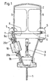
- FIG. 1 shows the suspension of a running rail 1 on a support 2 by means of a bolt 3, which is pivotally connected at the top with a cross member 4 in a small angular range.
- the cross member 4 is fixed via a screw 5 with the lower flange 6 of the double-T-shaped carrier 2 connected.
- the cross member 4 is with his upper bearing surface 7 on the lower outer surface 8 of the flange below Kraftbeaufschlagung on.
- the bolt 3 is at its lower End also in a limited angular range pivotally fixed to the rail 1 connected.
- a cable 9 is provided in addition to the suspension with the bolt 3, over which the carrier 2 and the rail 1 are connected to each other. This goes to this Rope around the carrier 2 around and is passed through the suspension of the rail 1. The ends of the rope 9 are firmly connected, so that the cable 9 a closed ring, which in case of failure of the suspension holding the Running rail 1 on the carrier 2 takes over.
- the ends 9a, 9b of the rope are fixed to each other by a connecting element 10 connected.
- the connecting element 10 is clearer in FIGS. 3 and 4 (top view) detect. It consists of a base plate 11, which carries a wedge lock 12, 13 on each side. Thus, the two wedge locks 12, 13 on the base plate 11 at the same time with each other connected. Each wedge lock thus consists of the common base plate 11 and a attached pocket 14, 15, which is formed in a metal sheet. The wedges are each rotated 180 degrees to each other; in the plan view in Fig. 4, the upper opening 16 of the Wedge lock 12 and the lower opening 17 of the wedge lock 13 can be seen.
- the interior the pockets 14, 15 is wedge-shaped and each has two side surfaces which in their imaginary extension at an acute angle, the wedge angle, each other run.
- the wedge angle is in the exemplary embodiment at 14 degrees.
- In the bag is one of Side a correspondingly shaped wedge 18, 19 can be inserted, which is essentially the same Wedge angle has.
- the ends of the rope run from in opposite directions in the wedge-shaped pockets and then around the wedge guided around.
- the wedge 18, 19 is freely displaceable at least in the inlet direction.
- the rope is partially transverse to its longitudinal direction on both sides of his Outer perimeter on the wedge and on the inner surfaces of the bag; it will be after Deflection about the wedges 18, 19 of the wedge locks 12, 13 against their direction of entry recycled. At least under load, the rope 9 of the wedges 18, 19 can be clamped.
- the Effective directions of the cable ends 9a, 9b clamping wedges 18, 19 are thus opposite.
- To secure the cable ends 9a, 9b are cable clamps 20a, 20b - as shown in Fig. 1 - intended.
Description
- Fig. 1
- einen Querschnitt durch einen Träger mit Redundanz-Aufhängung,
- Fig. 2
- eine Vorderansicht der Aufhängung gemäß Fig. 1,
- Fig. 3
- eine Vorderansicht eines Verbindungselements und
- Fig. 4
- eine Draufsicht auf das Verbindungselement gemäß Fig. 3 mit den im Innem geführten Stahlseilen im Querschnitt.
- 1
- Fahrschiene
- 2
- Träger
- 3
- Bolzen
- 4
- Querträger
- 5
- Schraubverbindung
- 6
- Flansch
- 7
- Auflagefläche
- 8
- Außenfläche
- 9
- Seil
- 9a, 9b
- Seilenden
- 10
- Verbindungselement
- 11
- Grundplatte
- 12
- Keilschloß
- 13
- Keilschloß
- 14
- Tasche
- 15
- Tasche
- 16
- obere Öffnung
- 17
- untere Öffnung
- 18
- Keil
- 19
- Keil
- 20a, 20b
- Seilklemmen
Claims (4)
- Aufhängung einer Fahrschiene eines Hebezeuges an einem Träger, mit mindestens ein den Träger und die Fahrschiene verbindendes Seil, dessen Enden durch ein Verbindungselement lösbar miteinander verbunden sind,
dadurch gekennzeichnet, dass das Verbindungselement (10) aus zwei baueinheitlich miteinander verbundenen Keilschlössern (12, 13) besteht, die derartig angeordnet sind, dass das eine Keilschloss (12) um 180 Grad zu dem anderen Keilschloss (13) verdreht ist, so dass die von entgegengesetzten Richtungen einlaufenden Seilenden (9a, 9b) nach Umlenkung um die Keile (18, 19) der Keilschlösser (12, 13) entgegen ihrer Einlaufrichtung zurückführbar von den Keilen (18, 19) mindestens unter Last klemmbar und dementsprechend die Wirkrichtungen der die Seilenden (9a, 9b) klemmenden Keile (18, 19) entgegengesetzt sind, und dass beide Keilschlösser (12, 13) im eingebauten Zustand seitlich nebeneinander angeordnet sind, wobei jedes Keilschloss (12, 13) aus einer Grundplatte (11) und einer aufgesetzten Tasche (14, 15) mit einem keilförmigen Innenraum zur Aufnahme des korrespondieren, einsteckbaren Keils (18, 19) gebildet ist und die Keilschlösser (12, 13) eine gemeinsame Grundplatte (11) als Verbindungselement (10) zwischen sich aufweisen. - Aufhängung nach Anspruch 1,
dadurch gekennzeichnet, dass der Keil (18, 19) in Einlaufrichtung frei verschiebbar ist. - Aufhängung nach Anspruch 1 oder 2,
dadurch gekennzeichnet, dass eine Seilklemme (20a, 20b) als Sicherung gegen ein Herausgleiten des Seils (9) aus dem Keilschloss (12, 13) vorgesehen ist. - Aufhängung nach einem der Ansprüche 1 bis 3,
dadurch gekennzeichnet, dass der Keilwinkel zwischen 10 und 16 Grad liegt.
Applications Claiming Priority (2)
| Application Number | Priority Date | Filing Date | Title |
|---|---|---|---|
| DE19727836A DE19727836C2 (de) | 1997-06-24 | 1997-06-24 | Aufhängung einer Fahrschiene für ein Hebezeug |
| DE19727836 | 1997-06-24 |
Publications (3)
| Publication Number | Publication Date |
|---|---|
| EP0887301A2 EP0887301A2 (de) | 1998-12-30 |
| EP0887301A3 EP0887301A3 (de) | 2000-10-04 |
| EP0887301B1 true EP0887301B1 (de) | 2005-11-16 |
Family
ID=7834146
Family Applications (1)
| Application Number | Title | Priority Date | Filing Date |
|---|---|---|---|
| EP98250196A Expired - Lifetime EP0887301B1 (de) | 1997-06-24 | 1998-06-05 | Aufhängung einer Fahrschiene eines Hebezeuges an einem Träger |
Country Status (7)
| Country | Link |
|---|---|
| US (1) | US6145443A (de) |
| EP (1) | EP0887301B1 (de) |
| JP (1) | JP3904729B2 (de) |
| KR (1) | KR19990006404A (de) |
| AT (1) | ATE309955T1 (de) |
| CA (1) | CA2240988A1 (de) |
| DE (2) | DE19727836C2 (de) |
Families Citing this family (4)
| Publication number | Priority date | Publication date | Assignee | Title |
|---|---|---|---|---|
| US6484368B1 (en) * | 2000-01-11 | 2002-11-26 | Otis Elevator Company | Flexible flat tension member termination device |
| DE102010037229A1 (de) * | 2010-08-30 | 2012-03-01 | Demag Cranes & Components Gmbh | Vorrichtung zum Aufhängen einer Schiene, insbesondere einer Schiene eines flurfreien Förderers oder eines Hebezeugs |
| CN105127573A (zh) * | 2015-08-31 | 2015-12-09 | 苏州斯尔特微电子有限公司 | 一种拉索结构的电子焊接机 |
| CN107458964A (zh) * | 2017-08-14 | 2017-12-12 | 安徽江淮汽车集团股份有限公司 | 车间内的转运机构 |
Family Cites Families (17)
| Publication number | Priority date | Publication date | Assignee | Title |
|---|---|---|---|---|
| US1380800A (en) * | 1921-06-07 | Worth | ||
| US1071868A (en) * | 1911-12-18 | 1913-09-02 | Jasper Blackburn | Guy-clamp. |
| US1622109A (en) * | 1926-11-01 | 1927-03-22 | Haworth Jehu Frederic | Cable or wire clamp |
| US1622110A (en) * | 1926-11-01 | 1927-03-22 | Haworth Jehu Frederic | Cable or wire clamp |
| US1644375A (en) * | 1927-01-10 | 1927-10-04 | Haworth Jehu Frederic | Cable or wire clamp |
| US1644376A (en) * | 1927-01-10 | 1927-10-04 | Haworth Jehu Frederic | Cable or wire clamp |
| GB315765A (en) * | 1928-07-17 | 1930-10-15 | Umberto Terzoll | Improvements relating to clamping devices for cables under tension |
| US1850896A (en) * | 1930-07-23 | 1932-03-22 | Sauerman Bros Inc | Cable securing means |
| US1955450A (en) * | 1933-02-15 | 1934-04-17 | Blackburn Jasper | Connecting clamp or splicer for cables |
| FR775474A (fr) * | 1933-07-14 | 1934-12-28 | Train E | Dispositif d'attache pour un ou plusieurs câbles |
| US2541425A (en) * | 1947-08-19 | 1951-02-13 | Elmer U Kunnas | Cable clamp |
| US3766610A (en) * | 1971-06-29 | 1973-10-23 | A Thorsbakken | Wedge locking device |
| US3906865A (en) * | 1972-06-09 | 1975-09-23 | Mcneil Corp | Material handling apparatus |
| US4718788A (en) * | 1986-08-05 | 1988-01-12 | Esco Corporation | Wire rope equalizer socket |
| US4809408A (en) * | 1987-09-21 | 1989-03-07 | Abrahamson Thomas C | Shielded wedge-type cable clamp |
| FR2648447B1 (fr) * | 1989-06-19 | 1991-09-06 | Geoffroy Roland | Monorail orientable pour palan |
| JP2534186B2 (ja) * | 1992-12-01 | 1996-09-11 | 株式会社キトー | 吊下げ走行装置 |
-
1997
- 1997-06-24 DE DE19727836A patent/DE19727836C2/de not_active Expired - Fee Related
-
1998
- 1998-04-27 KR KR1019980014909A patent/KR19990006404A/ko active IP Right Grant
- 1998-06-05 DE DE59813189T patent/DE59813189D1/de not_active Expired - Lifetime
- 1998-06-05 EP EP98250196A patent/EP0887301B1/de not_active Expired - Lifetime
- 1998-06-05 AT AT98250196T patent/ATE309955T1/de not_active IP Right Cessation
- 1998-06-16 JP JP18560598A patent/JP3904729B2/ja not_active Expired - Fee Related
- 1998-06-19 CA CA002240988A patent/CA2240988A1/en not_active Abandoned
- 1998-06-22 US US09/102,505 patent/US6145443A/en not_active Expired - Lifetime
Also Published As
| Publication number | Publication date |
|---|---|
| EP0887301A3 (de) | 2000-10-04 |
| JP3904729B2 (ja) | 2007-04-11 |
| DE19727836C2 (de) | 1999-08-12 |
| ATE309955T1 (de) | 2005-12-15 |
| EP0887301A2 (de) | 1998-12-30 |
| DE19727836A1 (de) | 1999-01-07 |
| US6145443A (en) | 2000-11-14 |
| KR19990006404A (ko) | 1999-01-25 |
| CA2240988A1 (en) | 1998-12-24 |
| JPH1121070A (ja) | 1999-01-26 |
| DE59813189D1 (de) | 2005-12-22 |
Similar Documents
| Publication | Publication Date | Title |
|---|---|---|
| EP2199247A2 (de) | Drehverbindung | |
| EP0887301B1 (de) | Aufhängung einer Fahrschiene eines Hebezeuges an einem Träger | |
| DE2841139C2 (de) | Verschluß zum Halten eines in einem Bremsbelagträger einschiebbaren Bremsbelages für Scheibenbremsen, insbesondere für Schienenfahrzeuge | |
| EP0002814A1 (de) | Betonschalung aus Schaltafeln mit Keilverbindung | |
| DE202016003698U1 (de) | Mobilkran | |
| DE3515156A1 (de) | Vorrichtung zum umscheren des hubseils bei einem kran mit einer auf einer hochgelegenen laufbahn verfahrbaren laufkatze | |
| EP0955263A2 (de) | Fahrwegbegrenzung für Fahrwerke, insbesondere von Hubwerken | |
| DE1808329C3 (de) | Flaschenzug mit von einem Schlitten getragenen oberen Seilrollen | |
| DE102004006179B4 (de) | Laufkatze | |
| DE806250C (de) | Stahlgelenkkappe | |
| DE3602902C2 (de) | ||
| DE2907963C2 (de) | Unterflasche für ein Hebezeug | |
| DE8137354U1 (de) | Anschlußvorrichtung | |
| DE2531730A1 (de) | Vorrichtung zur handhabung von rinnenfoermigen profilabschnitten fuer den untertaegigen streckenausbau | |
| DD279454A1 (de) | Rollenbahn | |
| DE3416097A1 (de) | Befestigung einer kranschiene auf einem kranbahntraeger | |
| DD291307A5 (de) | Verfahren und kupplungselement zum paketierten transport grossflaechiger hohlkoerper | |
| DE1180911B (de) | Selbsttaetig nachspannende Seilklemme fuer Bergbau-Schachtfoerderanlagen | |
| DE7903210U1 (de) | Kran | |
| EP1213505A1 (de) | Vorrichtung zum Befestigen eines Seilendes an einer Platte | |
| DE3119023A1 (de) | Betonschalung | |
| DD252595A1 (de) | Lastaufnahmemittel fuer stahlspundbohlen | |
| DE3122618A1 (de) | Vorrichtung zur schaffung einer loesbaren verbindung zwischen einem hebezeug und einem an einem zu hebenden werkstueck befestigten zugelement | |
| DE1190261B (de) | Klemme zum loesbaren Verbinden von Profilschienen oder -traegern | |
| DD226264A1 (de) | Vorrichtung zum transport flaechenartiger beton- oder stahlbetonelemente |
Legal Events
| Date | Code | Title | Description |
|---|---|---|---|
| PUAI | Public reference made under article 153(3) epc to a published international application that has entered the european phase |
Free format text: ORIGINAL CODE: 0009012 |
|
| AK | Designated contracting states |
Kind code of ref document: A2 Designated state(s): AT BE DE ES FR GB IE IT NL SE |
|
| AX | Request for extension of the european patent |
Free format text: AL;LT;LV;MK;RO;SI |
|
| PUAL | Search report despatched |
Free format text: ORIGINAL CODE: 0009013 |
|
| AK | Designated contracting states |
Kind code of ref document: A3 Designated state(s): AT BE CH CY DE DK ES FI FR GB GR IE IT LI LU MC NL PT SE |
|
| AX | Request for extension of the european patent |
Free format text: AL;LT;LV;MK;RO;SI |
|
| 17P | Request for examination filed |
Effective date: 20010205 |
|
| AKX | Designation fees paid |
Free format text: AT BE DE ES FR GB IE IT NL SE |
|
| 17Q | First examination report despatched |
Effective date: 20040521 |
|
| RAP1 | Party data changed (applicant data changed or rights of an application transferred) |
Owner name: DEMAG CRANES & COMPONENTS GMBH |
|
| RTI1 | Title (correction) |
Free format text: SUSPENSION OF THE TRACK OF A LIFTING APPARATUS ON A SUPPORT |
|
| GRAP | Despatch of communication of intention to grant a patent |
Free format text: ORIGINAL CODE: EPIDOSNIGR1 |
|
| GRAS | Grant fee paid |
Free format text: ORIGINAL CODE: EPIDOSNIGR3 |
|
| GRAA | (expected) grant |
Free format text: ORIGINAL CODE: 0009210 |
|
| AK | Designated contracting states |
Kind code of ref document: B1 Designated state(s): AT BE DE ES FR GB IE IT NL SE |
|
| PG25 | Lapsed in a contracting state [announced via postgrant information from national office to epo] |
Ref country code: NL Free format text: LAPSE BECAUSE OF FAILURE TO SUBMIT A TRANSLATION OF THE DESCRIPTION OR TO PAY THE FEE WITHIN THE PRESCRIBED TIME-LIMIT Effective date: 20051116 Ref country code: IE Free format text: LAPSE BECAUSE OF FAILURE TO SUBMIT A TRANSLATION OF THE DESCRIPTION OR TO PAY THE FEE WITHIN THE PRESCRIBED TIME-LIMIT Effective date: 20051116 |
|
| REG | Reference to a national code |
Ref country code: GB Ref legal event code: FG4D Free format text: NOT ENGLISH |
|
| REG | Reference to a national code |
Ref country code: IE Ref legal event code: FG4D Free format text: LANGUAGE OF EP DOCUMENT: GERMAN |
|
| REF | Corresponds to: |
Ref document number: 59813189 Country of ref document: DE Date of ref document: 20051222 Kind code of ref document: P |
|
| PG25 | Lapsed in a contracting state [announced via postgrant information from national office to epo] |
Ref country code: SE Free format text: LAPSE BECAUSE OF FAILURE TO SUBMIT A TRANSLATION OF THE DESCRIPTION OR TO PAY THE FEE WITHIN THE PRESCRIBED TIME-LIMIT Effective date: 20060216 |
|
| PG25 | Lapsed in a contracting state [announced via postgrant information from national office to epo] |
Ref country code: ES Free format text: LAPSE BECAUSE OF FAILURE TO SUBMIT A TRANSLATION OF THE DESCRIPTION OR TO PAY THE FEE WITHIN THE PRESCRIBED TIME-LIMIT Effective date: 20060227 |
|
| GBT | Gb: translation of ep patent filed (gb section 77(6)(a)/1977) |
Effective date: 20060224 |
|
| NLV1 | Nl: lapsed or annulled due to failure to fulfill the requirements of art. 29p and 29m of the patents act | ||
| REG | Reference to a national code |
Ref country code: IE Ref legal event code: FD4D |
|
| PG25 | Lapsed in a contracting state [announced via postgrant information from national office to epo] |
Ref country code: BE Free format text: LAPSE BECAUSE OF NON-PAYMENT OF DUE FEES Effective date: 20060630 |
|
| ET | Fr: translation filed | ||
| PLBE | No opposition filed within time limit |
Free format text: ORIGINAL CODE: 0009261 |
|
| STAA | Information on the status of an ep patent application or granted ep patent |
Free format text: STATUS: NO OPPOSITION FILED WITHIN TIME LIMIT |
|
| 26N | No opposition filed |
Effective date: 20060817 |
|
| PG25 | Lapsed in a contracting state [announced via postgrant information from national office to epo] |
Ref country code: AT Free format text: LAPSE BECAUSE OF NON-PAYMENT OF DUE FEES Effective date: 20060605 |
|
| BERE | Be: lapsed |
Owner name: DEMAG CRANES & COMPONENTS G.M.B.H. Effective date: 20060630 |
|
| PGFP | Annual fee paid to national office [announced via postgrant information from national office to epo] |
Ref country code: GB Payment date: 20140618 Year of fee payment: 17 |
|
| PGFP | Annual fee paid to national office [announced via postgrant information from national office to epo] |
Ref country code: DE Payment date: 20140619 Year of fee payment: 17 Ref country code: IT Payment date: 20140627 Year of fee payment: 17 |
|
| PGFP | Annual fee paid to national office [announced via postgrant information from national office to epo] |
Ref country code: FR Payment date: 20140619 Year of fee payment: 17 |
|
| REG | Reference to a national code |
Ref country code: DE Ref legal event code: R119 Ref document number: 59813189 Country of ref document: DE |
|
| PG25 | Lapsed in a contracting state [announced via postgrant information from national office to epo] |
Ref country code: IT Free format text: LAPSE BECAUSE OF NON-PAYMENT OF DUE FEES Effective date: 20150605 |
|
| GBPC | Gb: european patent ceased through non-payment of renewal fee |
Effective date: 20150605 |
|
| REG | Reference to a national code |
Ref country code: FR Ref legal event code: ST Effective date: 20160229 |
|
| PG25 | Lapsed in a contracting state [announced via postgrant information from national office to epo] |
Ref country code: GB Free format text: LAPSE BECAUSE OF NON-PAYMENT OF DUE FEES Effective date: 20150605 Ref country code: DE Free format text: LAPSE BECAUSE OF NON-PAYMENT OF DUE FEES Effective date: 20160101 |
|
| PG25 | Lapsed in a contracting state [announced via postgrant information from national office to epo] |
Ref country code: FR Free format text: LAPSE BECAUSE OF NON-PAYMENT OF DUE FEES Effective date: 20150630 |