EP0887525A2 - Compression-ignition type engine - Google Patents
Compression-ignition type engine Download PDFInfo
- Publication number
- EP0887525A2 EP0887525A2 EP98111562A EP98111562A EP0887525A2 EP 0887525 A2 EP0887525 A2 EP 0887525A2 EP 98111562 A EP98111562 A EP 98111562A EP 98111562 A EP98111562 A EP 98111562A EP 0887525 A2 EP0887525 A2 EP 0887525A2
- Authority
- EP
- European Patent Office
- Prior art keywords
- fuel
- injection
- compression
- engine
- amount
- Prior art date
- Legal status (The legal status is an assumption and is not a legal conclusion. Google has not performed a legal analysis and makes no representation as to the accuracy of the status listed.)
- Granted
Links
Images


Classifications
-
- F—MECHANICAL ENGINEERING; LIGHTING; HEATING; WEAPONS; BLASTING
- F02—COMBUSTION ENGINES; HOT-GAS OR COMBUSTION-PRODUCT ENGINE PLANTS
- F02B—INTERNAL-COMBUSTION PISTON ENGINES; COMBUSTION ENGINES IN GENERAL
- F02B3/00—Engines characterised by air compression and subsequent fuel addition
- F02B3/06—Engines characterised by air compression and subsequent fuel addition with compression ignition
-
- F—MECHANICAL ENGINEERING; LIGHTING; HEATING; WEAPONS; BLASTING
- F02—COMBUSTION ENGINES; HOT-GAS OR COMBUSTION-PRODUCT ENGINE PLANTS
- F02D—CONTROLLING COMBUSTION ENGINES
- F02D41/00—Electrical control of supply of combustible mixture or its constituents
- F02D41/30—Controlling fuel injection
- F02D41/3011—Controlling fuel injection according to or using specific or several modes of combustion
- F02D41/3017—Controlling fuel injection according to or using specific or several modes of combustion characterised by the mode(s) being used
- F02D41/3035—Controlling fuel injection according to or using specific or several modes of combustion characterised by the mode(s) being used a mode being the premixed charge compression-ignition mode
-
- F—MECHANICAL ENGINEERING; LIGHTING; HEATING; WEAPONS; BLASTING
- F02—COMBUSTION ENGINES; HOT-GAS OR COMBUSTION-PRODUCT ENGINE PLANTS
- F02D—CONTROLLING COMBUSTION ENGINES
- F02D41/00—Electrical control of supply of combustible mixture or its constituents
- F02D41/30—Controlling fuel injection
- F02D41/38—Controlling fuel injection of the high pressure type
- F02D41/3809—Common rail control systems
- F02D41/3827—Common rail control systems for diesel engines
-
- F—MECHANICAL ENGINEERING; LIGHTING; HEATING; WEAPONS; BLASTING
- F02—COMBUSTION ENGINES; HOT-GAS OR COMBUSTION-PRODUCT ENGINE PLANTS
- F02D—CONTROLLING COMBUSTION ENGINES
- F02D41/00—Electrical control of supply of combustible mixture or its constituents
- F02D41/30—Controlling fuel injection
- F02D41/38—Controlling fuel injection of the high pressure type
- F02D41/40—Controlling fuel injection of the high pressure type with means for controlling injection timing or duration
- F02D41/402—Multiple injections
-
- F—MECHANICAL ENGINEERING; LIGHTING; HEATING; WEAPONS; BLASTING
- F02—COMBUSTION ENGINES; HOT-GAS OR COMBUSTION-PRODUCT ENGINE PLANTS
- F02B—INTERNAL-COMBUSTION PISTON ENGINES; COMBUSTION ENGINES IN GENERAL
- F02B1/00—Engines characterised by fuel-air mixture compression
- F02B1/12—Engines characterised by fuel-air mixture compression with compression ignition
-
- Y—GENERAL TAGGING OF NEW TECHNOLOGICAL DEVELOPMENTS; GENERAL TAGGING OF CROSS-SECTIONAL TECHNOLOGIES SPANNING OVER SEVERAL SECTIONS OF THE IPC; TECHNICAL SUBJECTS COVERED BY FORMER USPC CROSS-REFERENCE ART COLLECTIONS [XRACs] AND DIGESTS
- Y02—TECHNOLOGIES OR APPLICATIONS FOR MITIGATION OR ADAPTATION AGAINST CLIMATE CHANGE
- Y02T—CLIMATE CHANGE MITIGATION TECHNOLOGIES RELATED TO TRANSPORTATION
- Y02T10/00—Road transport of goods or passengers
- Y02T10/10—Internal combustion engine [ICE] based vehicles
- Y02T10/40—Engine management systems
Definitions
- the present invention relates to a compression-ignition type engine.
- a compression-ignition type engine In a compression-ignition type engine, the degree of dispersion of the fuel injected into the combustion chamber has a major effect on the combustion. That is, if the fuel is made to disperse throughout the combustion chamber, the amount of heat generated per unit volume becomes lower, so the combustion temperature becomes lower and therefore smooth combustion is achieved without the generation of NOx. Further, since there is sufficient air present around the fuel particles, soot is no longer generated either. Therefore, known in the art is a compression-ignition type engine which is designed to inject fuel during the compression stroke before 60 degrees before top dead center (see Japanese Unexamined Patent Publication (Kokai) No. 7-317588).
- this compression-ignition type engine was designed to inject the fuel before 60 degrees before top dead center in the compression stroke where the pressure in the combustion chamber is low.
- the ignition timing can no longer be controlled to the ignition timing giving a smooth combustion when the amount of injected fuel becomes large. If it were possible to control the ignition timing to the ignition timing giving smooth combustion in this case, then it would be possible to achieve smooth combustion with little generation of NOx and soot.
- An object of the present invention is to provide a compression-ignition type engine which is capable of controlling the ignition timing to an ignition timing giving a smooth combustion.
- a compression-ignition type engine comprising a combustion chamber; a fuel injector injecting fuel toward the inside of the combustion chamber, an operating region of the engine being divided into a first operating region of a low load side and a second operating region of a high load side; injection control means for causing injection of fuel at least once before 50 degrees before top dead center of the compression stroke to cause combustion of the injected fuel when an operating state of the engine is in the first operating region, the injection control means injecting an amount of first fuel by which amount combustion does not occur even if injected, in a predetermined injection timing region of a latter half of a compression stroke where combustion does not occur even if injected, and causing injection of second fuel at a timing later than the predetermined injection timing region to cause combustion of the first fuel and the second fuel when the operating state of the engine is in the second operating region.
- FIG. 1 designates an engine body, 2 a cylinder block, 3 a cylinder head, 4 a piston, 5 a combustion chamber, 6 an electrically controlled fuel injector, 7 an intake valve, 8 an intake port, 9 an exhaust valve, and 10 an exhaust port.
- the intake port 8 is connected through a corresponding intake pipe 11 to a surge tank 12.
- the surge tank 12 is connected to a compressor 15 of an exhaust turbocharger 14 through an intake duct 13.
- the exhaust port 10 is connected through an exhaust manifold 16 and exhaust pipe 17 to an exhaust turbine 18 of an exhaust turbocharger 14.
- the outlet of the exhaust turbine 18 is connected to a catalytic converter 20 housing a three-way catalyst 19. Further, an air-fuel ratio sensor 21 is disposed in the exhaust manifold 16.
- the exhaust manifold 16 and surge tank 12 are connected with each other through an exhaust gas recirculation (hereinafter referred to as "EGR") passage 22.
- EGR exhaust gas recirculation
- the fuel injectors 6 are connected through fuel supply pipes 24 to a fuel reservoir, that is, a so-called common rail 25.
- the common rail 25 is supplied with fuel from an electrically controlled variable discharge fuel pump 26.
- the fuel supplied in the common rail 25 is supplied through the fuel supply pipes 24 to the fuel injectors 6.
- the common rail 25 is provided with a fuel pressure sensor 27 for detecting the fuel pressure in the common rail 25.
- the output signal of the fuel pressure sensor 27 is used to control the discharge of the fuel pump 26 so that the fuel pressure in the common rail 25 becomes the target fuel pressure.
- An electronic control unit 30 is comprised of a digital computer and is provided with a read only memory (ROM) 32, random access memory (RAM) 33, microprocessor (CPU) 34, input port 35, and output port 36 connected to each other through a bidirectional bus 31.
- the output signal of the air-fuel ratio sensor 21 is input through a corresponding AD converter 37 to the input port 35. Further, the output signal of the fuel pressure sensor 27 is input through a corresponding AD converter 37 to the input port 35.
- An accelerator pedal 40 has connected to it a load sensor 41 for generating an output voltage proportional to the amount of depression L of the accelerator pedal 40. The output voltage of the load sensor 41 is input through a corresponding AD converter 37 to the input port 35.
- the input port 35 has connected to it a crank angle sensor 42 which generates an output pulse with each for example 30 degree revolution of the crankshaft.
- the output port 36 is connected through a corresponding drive circuit 38 to the fuel injectors 6, EGR control valve 23, and fuel pump 26.
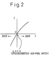
- Figure 2 shows the output current I of the air-fuel ratio sensor 21.
- the air-fuel ratio sensor 21 generates an output current I in accordance with the air excess rate ⁇ , that is, the air-fuel ratio, therefore it is possible to find the air-fuel ratio from the output current I of the air-fuel ratio sensor 21.
- the output current I is converted to voltage and input to the corresponding AD converter 37.
- the fuel injector 6 is comprised of a nozzle having a large number of nozzle openings.
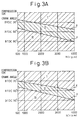
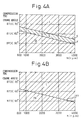
- Figs. 3A and 3B and Figs. 4A and 4B the ordinate indicates the crank angle, while the abscissa indicates the engine speed N.
- Fig. 3A shows the case of injection of fuel in an amount of 5 percent of the maximum amount of injection
- Fig. 3B shows the case of injection of fuel in an amount of 10 percent of the maximum amount of injection
- Fig. 4A shows the case of injection of fuel in an amount of 20 percent of the maximum amount of injection
- Fig. 4B shows the case of injection of fuel in an amount of over 30 percent of the maximum amount of injection.
- I indicates an injection timing region where normal combustion occurs as in the past when fuel is injected at an injection timing in the region
- II shows an injection timing region where no combustion occurs when fuel is injected at an injection timing in the region
- III shows an injection timing region where almost no NOx or soot is generated when fuel is injected at an injection timing in the region.
- Whether or not the injected fuel burns depends on the density of the fuel particles and the temperature of the fuel particles. Simply speaking, when the density of the fuel particles is relatively low, combustion occurs if the temperature of the fuel particles is high and does not occur if the temperature of the fuel particles is low. As opposed to this, when the density of the fuel particles is high, combustion occurs regardless of the temperature of the fuel particles.
- combustion occurs regardless of the temperature of the fuel particles if the density of the fuel particles is high, but the combustion at that time is explosive and generates a large amount of NOx and a large amount of soot. That is, the injected fuel undergoes a chemical reaction when the temperature in the combustion chamber 5 is more than 700°K. Before about 30 degrees BTDC, the temperature in the combustion chamber 5 is less than 700°K, therefore if the fuel is injected before 30 degrees BTDC, the injected fuel disperses in the combustion chamber 5 without undergoing a chemical reaction. Next, when the piston 4 rises and the temperature in the combustion chamber 5 becomes higher than a certain temperature, the evaporated fuel around the fuel particles bonds with oxygen. Explaining this in more detail, the terminal carbons of the straight chain hydrocarbons are attacked by the oxygen radicals resulting in the formation of aldehyde groups at the terminals of the straight chain hydrocarbons, then the aldehyde groups become hydroxy groups.
- the fuel particles become close together at this time, that is, when the density of the fuel particles is high, the fuel particles receive the heat of oxidation of the evaporated fuel of the surrounding fuel particles and become high in temperature. As a result, the hydrocarbons in the fuel particles are broken down into hydrogen molecules H 2 and carbon C. The hydrogen molecules H 2 produced by this thermal decomposition explosively burn and generate a high temperature, therefore NOx is produced. On the other hand, when carbon C is produced by the thermal decomposition, the carbon atoms bond with each other and part is discharged as soot. In this way, when the density of the fuel particles is high, even if the fuel particles can be dispersed in the combustion chamber 5 without undergoing a chemical reaction, NOx and soot are produced due to the thermal decomposition of the hydrocarbons in the fuel particles.
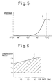
- the curve of Fig. 5 shows the change in the pressure P in the combustion chamber 5 due to just the compression action of the piston 4.
- the pressure P in the combustion chamber 5 rises rapidly when about 60 degrees BTDC is exceeded. This is regardless of the timing of opening of the intake valve 7.
- the pressure P in the combustion chamber 5 changes as shown in Fig. 5 in all types of reciprocating internal combustion engines. If the pressure P in the combustion chamber 5 becomes high, the air resistance becomes great, so the injected fuel will not disperse over a wide range. To get the injected fuel to disperse over a wide range, it is necessary to inject the fuel when the pressure P in the combustion chamber 5 is low.
- the injection timing region III is about 50 degrees BTDC. Therefore, if fuel is injected in the injection timing region III, the fuel particles disperse over a wide range. Further, since the amount of fuel injected is less than 30 percent of the maximum amount of injection, the density of the fuel particles in the combustion chamber becomes considerably low.
- the space between fuel particles becomes larger. Therefore, when the evaporated fuel around the fuel particles bond with oxygen, the fuel particles do not receive much of the heat of oxidation of the evaporated fuel of the surrounding fuel particles and therefore the fuel particles do not break down under heat. As a result, almost no hydrogen molecules H 2 or carbon C are produced. Next, when the compression stroke continues and the temperature of the fuel particles becomes higher, the evaporated fuel of the fuel particles substantially simultaneously start to burn.
- the evaporated fuel of the fuel particles substantially simultaneously start to burn in this way, there will not be any local high temperatures. Further, since the fuel particles are dispersed, the amount of heat generated per unit volume falls. As a result, the combustion temperature falls as a whole and therefore smooth combustion without generation of NOx is obtained. Further, since there is sufficient air present around the fuel particles, soot is no longer be produced either.
- Figs. 3A, 3B, and 4A show cases where the amounts of fuel injected are 5 percent, 10 percent, and 20 percent of the maximum amount of fuel injection. If fuel is injected in the injection timing region III at this time, smooth combustion without generation of NOx or soot is obtained. Further, Fig. 4B shows the case where the amount of fuel injected is over 30 percent of the maximum amount of fuel injection. If fuel is injected in the injection timing region III, smooth combustion without generation of NOx and soot can be obtained up to an amount of fuel injection of about 50 percent of the maximum amount of injection. When the amount of fuel injected exceeds about 50 percent of the maximum amount of injection, the density of the fuel particles is high even if the fuel particles are dispersed, so NOx and soot are produced.
- the latest injection timing of the injection timing region III that is, in Figs. 3A, 3B, and 4A, the boundary Y between the injection timing region III and the injection timing region II and, in Fig. 4B, the boundary XY between the injection timing period III and the injection timing period I, is substantially the same regardless of the amount of injection. That is, the boundaries Y and XY are near 50 degrees BTDC when the engine speed N is 600 rpm. The higher the engine speed N becomes, the more they shift to bottom dead center of the compression stroke. When the engine speed N is 4000 rpm, they become about 90 degrees BTDC.
- the temperature in the combustion chamber 5 is less than 700°K, therefore if fuel is injected in the injection timing region II, no chemical reaction occurs. Further, since the pressure P in the combustion chamber 5 is higher in the injection timing region II than the injection timing region III, the degree of dispersion of the fuel particles is lower than in the injection timing region III. Since the amount of fuel injected is less than 30 percent of the maximum amount of injection, however, the density of the fuel particles is relatively small even if the degree of dispersion of the fuel particles falls somewhat.
- the density of the fuel particles is low in this way, the space between fuel particles becomes greater and therefore, as explained above, the fuel particles do not receive much of the heat of oxidation of the evaporated fuel of the surrounding fuel particles and so do not break down under heat. Therefore, no explosive combustion occurs.
- the top dead center of the compression stroke is reached in this state, that is, in the state with an increase in the amount of oxygen-containing easily burnable hydrocarbons without combustion. If nothing is then done, the fuel will not ignite resulting in a misfire.
- the latest injection timing in the injection timing region II that is, the boundary X between the injection timing region II and the injection timing region I
- the width of the injection timing region II in other words, the width between the boundary X and the boundary Y
- the width between the boundary X and the boundary Y becomes smaller the larger the ratio of the amount of injection to the maximum amount of injection.
- the injection timing region II disappears.
- the boundary X when the engine speed N is 600 rpm is about 20 degrees BTDC and the width between the boundary X and the boundary Y increases from about 30 degrees crank angle to about 40 degrees crank angle.
- the boundary X when the engine speed N is 600 rpm is about 30 degrees BTDC and the width between the boundary X and the boundary Y increases from about 20 degrees crank angle to about 30 degrees crank angle.
- the amount of injection is 20 percent of the maximum amount of injection, as shown in Fig.
- the boundary X when the engine speed N is 600 rpm is about 40 degrees BTDC and the width between the boundary X and the boundary Y increases from about 10 degrees crank angle to about 15 degrees crank angle.
- the injection timing region II disappears.
- the density of the fuel particles becomes greater, therefore when the amount of fuel injection is increased, the degree of dispersion of the fuel particles has to be increased or else combustion will occur.
- the degree of dispersion of fuel particles becomes higher the earlier the injection timing, therefore the width of the injection timing region II becomes smaller the larger the amount of injection.
- the injection timing region II shifts to the low load side the higher the engine speed N. That is, as explained above, it takes time for the injected fuel to disperse. If the injection timing is not made earlier the higher the engine speed N, the degree of dispersion of the fuel particles will not become smaller. Therefore, the injection timing region II shifts to the low load side the higher the engine speed N. Note that the boundary X is expressed clearer than the boundaries Y and XY.
- the injection timing region can be divided into the injection timing region I where explosive combustion occurs, the injection timing region III where smooth combustion occurs without the generation of NOx and soot, and the injection timing region II where no combustion occurs between the injection timing regions I and III.
- the injection timing region can be divided into the injection timing region I and the injection timing region III.
- the solid line E in Fig. 6 shows the upper limit of the engine compression ratio in the injection timing region II where no combustion occurs as shown in Figs. 3A, 3B, and 4A.
- the upper limit E of the engine compression ratio in the injection timing region II where no combustion occurs is about 16.0. If the engine compression ratio becomes larger than about 16.0, there is no longer an injection timing region II where no combustion occurs.
- the upper limit E of the engine compression ratio in the injection timing region II where no combustion occurs becomes higher the higher the EGR rate. Further, to cause compression ignition, the engine compression ratio must be made at least about 12.0. Therefore, the range of engine compression ratio in the injection timing region II where no combustion occurs becomes the range shown by the hatching in Fig. 6.
- the oxygen-containing easily burnable hydrocarbons dispersed in the combustion chamber 5 as a whole simultaneously start to burn, whereby the fuel particles injected the second time can be burned. If combustion is started simultaneously throughout the combustion chamber 5 in this way, there is no local rise in the combustion temperature and the combustion temperature in the combustion chamber 5 becomes lower as a whole, so generation of NOx is suppressed. Further, since the fuel injected the second time can be burned after being dispersed, there is sufficient air present around the fuel particles and therefore the generation of soot is also suppressed.
- first fuel of an amount of not more than 30 percent of the maximum amount of injection is injected in the injection timing region II and then second fuel is injected at substantially top dead center of the compression stroke or after top dead center of the compression stroke, it is possible to obtain smooth combustion with little generation of NOx and soot.
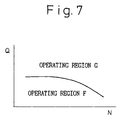
- the engine operating region is divided into a first operating region F at the low load side and a second operating region G at a high load side.
- fuel is injected at least once in the injection timing region III, while when the engine is in the operating region G, first fuel of not more than 30 percent of the maximum amount of injection is injected in the injection timing region II, then the second fuel is injected at substantially the top dead center of the compression stroke or after top dead center of the compression stroke.
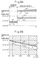
- Figure 8A shows the injection timings of the fuel injection I at the operating region F and the first fuel injection I 1 and the second fuel injection I 2 at the operating region G at a specific engine speed N, for example, 1500 rpm.
- Figure 8B shows the injection timing of the first fuel injection I 1 at the operating region G. Note that the abscissa Q of Fig. 8A shows the total amount of fuel injection Q, while the abscissa N of Fig. 8B shows the engine speed.
- ⁇ S and ⁇ E in the operating region F show the injection start timing and the injection end timing of the fuel injection I
- ⁇ S1 and ⁇ E1 in the operating region G show the injection start timing and the injection end timing of the first fuel injection I 1
- ⁇ S2 and ⁇ E2 in the operating region G show the injection start timing and injection end timing of the second fuel injection I 2
- Figs. 8A and 8B show the case where the fuel pressure in the common rail 25 is maintained at a certain constant pressure. Therefore, in Figs. 8A and 8B, the amount of fuel injection is proportional to the injection timing.
- the injection end timing ⁇ E of the fuel injection I is fixed to substantially 70 degrees BTDC, therefore in this embodiment, a single fuel injection is performed near 70 degrees BTDC.
- the first fuel injection I 1 in the operating region G is performed at a timing close to the relative boundary X in the injection timing region II, therefore the timing of the first fuel injection I 1 is made earlier the higher the engine speed N.
- the amount of injection of the first fuel injection I 1 is made 10 percent of the maximum amount of injection.
- the injection start timing ⁇ S2 of the second fuel injection I 2 is fixed to the top dead center of the compression stroke (TDC).
- the total amount of fuel injection Q is a function of the amount of depression L of the accelerator pedal 40 and the engine speed N.
- the total amount of fuel injection Q is stored in advance in the ROM 32 in the form of the map shown in Fig. 9A.
- the injection amount Q1 of the first fuel injection I 1 is a function of the total amount of fuel injection Q and the engine speed N.
- the injection amount Q1 is also stored in advance in the ROM 32 in the form of the map shown in Fig. 9B.
- the injection start timing ⁇ S1 of the first fuel injection I 1 is also a function of the total amount of fuel injection Q and the engine speed N.
- the injection start timing ⁇ S1 is also stored in advance in the ROM 32 in the form of the map shown in Fig. 9C.
- Figure 10 shows the injection control routine. Referring to Fig. 10, first, at step 50, the total amount of fuel injection Q is calculated from the map shown in Fig. 9A. Next, at step 51, it is judged if the operating state of the engine is in the operating region F of Fig. 7 or not. When the engine operating state is in the operating region F, the routine proceeds to step 52, where the injection start timing ⁇ S of the fuel injection I is calculated based on the total amount of fuel injection Q. As opposed to this, when the engine operating state is not in the operating region F, that is, is in the operating region G of Fig. 7, the routine proceeds to step 53, where the injection amount Q1 of the first fuel injection I 1 is calculated from the map shown in Fig. 9B.
- the injection start timing ⁇ S1 of the first fuel injection I 1 is calculated from the map shown in Fig. 9C.
- the injection end timing ⁇ E1 of the first fuel injection I 1 is calculated based on the injection amount Q1 and the injection start timing ⁇ S1.
- the injection end timing ⁇ E2 of the second fuel injection I 2 is calculated based on the total amount of fuel injection Q and the fuel injection Q1 etc.
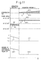
- FIG. 11 to Fig. 14 show another embodiment.
- the air excess rate ⁇ is controlled to 1.0 as shown by ⁇ 2 in Fig. 11. That is, the air-fuel ratio is controlled to the stoichiometric air-fuel ratio. If the air-fuel ratio is controlled to the stoichiometric air-fuel ratio, the NOx and hydrocarbons can be removed well by the three-way catalyst 19 and therefore the release of NOx and hydrocarbons into the atmosphere can be prevented.
- the amount of EGR gas is controlled to control the air-fuel ratio to the stoichiometric air-fuel ratio.
- the basic opening degree G ⁇ 2 of the EGR control valve 23 required for making the air-fuel ratio the stoichiometric air-fuel ratio becomes a function of the total amount of fuel injection Q and the engine speed N.
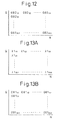
- This basic opening degree G ⁇ 2 is stored in advance in the ROM 32 in the form of the map shown in Fig. 12.
- the air excess rate ⁇ is controlled to a value larger than 1.0 as shown by ⁇ 1 in Fig. 11. Further, the air excess rate ⁇ is reduced the greater the total amount of fuel injection Q.
- the target air excess rate ⁇ 1 in the operating region F is in actuality a function of the amount of fuel injection Q and the engine speed.
- the target air excess rate ⁇ 1 is stored in advance in the ROM 32 in the form of the map shown in Fig. 13A.
- the basic opening degree G ⁇ 1 of the EGR control valve 23 required for making the air excess rate ⁇ the target air excess rate ⁇ 1 is a function of the amount of fuel injection Q and the engine speed N.
- This basic opening degree G ⁇ 2 is also stored in advance in the ROM 32 in the form of the map shown in Fig. 13B.
- Figure 14 shows a routine for injection control. Referring to Fig. 14, first, at step 60, the total amount of fuel injection Q is calculated from the map shown in Fig. 9A. Next, at step 61, it is judged if the operating state of the engine is in the operating region F of Fig. 7 or not. When the engine operating state is in the operating region F, the routine proceeds to step 62.
- the injection start timing ⁇ S is calculated based on the total amount of fuel injection Q.
- the target air excess rate ⁇ 1 is calculated from the map shown in Fig. 13A
- the basic opening degree G ⁇ 1 of the EGR control valve 23 is calculated from the map shown in Fig. 13B.
- the routine proceeds to step 66, where a constant value ⁇ is added to the correction value ⁇ 1, then the routine proceeds to step 68.
- step 67 the routine proceeds to step 67, where the constant value ⁇ is subtracted from the correction value ⁇ 1, then the routine proceeds to step 68.
- step 68 the correction value ⁇ 1 is added to the basic opening degree G ⁇ 1 to calculate the final opening degree G ⁇ of the EGR control valve 23.
- step 61 when it is judged at step 61 that the engine operating state is not in the operating state F, that is, the engine operating state is in the operating region G, the routine proceeds to step 69, where the injection amount Q1 of the first fuel injection I 1 is calculated from the map shown in Fig. 9B.
- step 70 the injection start timing ⁇ S1 of the first fuel injection I 1 is calculated from the map shown in Fig. 9C.
- step 71 the injection end timing ⁇ E1 of the first fuel injection I 1 is calculated based on the injection amount Q1 and the injection start timing ⁇ S1.
- step 72 the injection end timing ⁇ E2 of the second fuel injection I 2 is calculated based on the total amount of fuel injection Q and the fuel injection Q1 etc.
- step 73 the basic opening degree G ⁇ 2 of the EGR control valve 23 is calculated from the map shown in Fig. 12.
- step 74 it is judged if the air excess rate ⁇ detected by the air-fuel ratio sensor 21 is larger than 1.0 or not.
- the routine proceeds to step 75, where a constant value ⁇ is added to the correction value ⁇ 2, then the routine proceeds to step 77.
- the routine proceeds to step 76, where the constant value ⁇ is subtracted from the correction value ⁇ 2, then the routine proceeds to step 77.
- step 77 the correction value ⁇ 2 is added to the basic opening degree G ⁇ 2 to calculate the final opening degree G ⁇ of the EGR control valve 23.
- a compression-ignition type engine in which the engine operating region is divided into a first operating region F of a low load side and a second operating region G of a high load side.
- first fuel injection I 1 of an amount of not more than 30 percent of the maximum amount of fuel is performed in an injection timing region II and second fuel injection I 2 is performed at substantially the top dead center of the compression stroke.
Abstract
Description
Claims (16)
- A compression-ignition type engine comprising:a combustion chamber;a fuel injector injecting fuel toward the inside of the combustion chamber, an operating region of the engine being divided into a first operating region of a low load side and a second operating region of a high load side; injection control means for causing injection of fuel at least once before 50 degrees before top dead center of the compression stroke to cause combustion of the injected fuel when an operating state of the engine is in the first operating region, said injection control means injecting an amount of first fuel by which amount combustion does not occur even if injected, in a predetermined injection timing region of a latter half of a compression stroke where combustion does not occur even if injected, and causing injection of second fuel at a timing later than the predetermined injection timing region to cause combustion of the first fuel and the second fuel when the operating state of the engine is in the second operating region.
- A compression-ignition type engine as set forth in claim 1, wherein the amount of the first fuel where combustion does not occur even with injection when the operating state of the engine is the second operating region is not more than 30 percent of the maximum amount of injection.
- A compression-ignition type engine as set forth in claim 1, wherein said predetermined injection timing region is from about 90 degrees before top dead center of the compression stroke to about 20 degrees before top dead center of the compression stroke.
- A compression-ignition type engine as set forth in claim 3, wherein the earliest injection timing in the predetermined injection timing region shifts toward the bottom dead center of the compression stroke the higher the engine speed and the latest injection timing in the predetermined injection timing region shifts toward the bottom dead center of the compression stroke the higher the engine speed.
- A compression-ignition type engine as set forth in claim 4, wherein the earliest injection timing is near 50 degrees before top dead center of the compression stroke when the engine speed is 600 rpm and near 90 degrees before top dead center of the compression stroke when the engine speed is 4000 rpm.
- A compression-ignition type engine as set forth in claim 4, wherein the latest injection timing shifts toward the bottom dead center of the compression stroke the larger the ratio of the amount of the first fuel injection to the maximum amount of injection and the difference between the earliest injection timing and the latest injection timing at the same engine speed becomes Smaller the larger the ratio.
- A compression-ignition type engine as set forth in claim 6, wherein when the amount of the first fuel injection is 5 percent of the maximum amount of injection and the engine speed is 600 rpm, the latest injection timing is about 20 degrees before top dead center of the compression stroke and the difference in injection timings is from about 30 degrees crank angle to 40 degrees crank angle.
- A compression-ignition type engine as set forth in claim 6, wherein when the amount of the first fuel injection is 10 percent of the maximum amount of injection and the engine speed is 600 rpm, the latest injection timing is about 30 degrees before top dead center of the compression stroke and the difference in injection timings is from about 20 degrees crank angle to 30 degrees crank angle.
- A compression-ignition type engine as set forth in claim 6, wherein when the amount of the first fuel injection is 20 percent of the maximum amount of injection and the engine speed is 600 rpm, the latest injection timing is about 40 degrees before top dead center of the compression stroke and the difference in injection timings is from about 10 degrees crank angle to 15 degrees crank angle.
- A compression-ignition type engine as set forth in claim 1, wherein the first fuel injection timing is made earlier the higher the engine speed when the operating state of the engine is in the second operating region.
- A compression-ignition type engine as set forth in claim 1, wherein the second fuel injection is performed at substantially top dead center of the compression stroke or after top dead center of the compression stroke when the operating state of the engine is in the second operating region.
- A compression-ignition type engine as set forth in claim 1, further comprising air-fuel ratio controlling means for controlling the air-fuel ratio to a predetermined target air-fuel ratio.
- A compression-ignition type engine as set forth in claim 12, wherein said target air-fuel ratio is made a lean air-fuel ratio when the operating state of the engine is in the first operating region.
- A compression-ignition type engine as set forth in claim 12, wherein said target air-fuel ratio is made the stoichiometric air-fuel ratio when the operating state of the engine is in the second operating region.
- A compression-ignition type engine as set forth in claim 12, wherein said air-fuel ratio controlling means controls the amount of exhaust gas recirculation to control the air-fuel ratio to the target air-fuel ratio.
- A compression-ignition type engine as set forth in claim 1, wherein a three-way catalyst is arranged in an engine exhaust passage.
Applications Claiming Priority (6)
| Application Number | Priority Date | Filing Date | Title |
|---|---|---|---|
| JP167632/97 | 1997-06-24 | ||
| JP16763297 | 1997-06-24 | ||
| JP16763297 | 1997-06-24 | ||
| JP3924498 | 1998-02-20 | ||
| JP39244/98 | 1998-02-20 | ||
| JP03924498A JP4010046B2 (en) | 1997-06-24 | 1998-02-20 | Compression ignition internal combustion engine |
Publications (3)
| Publication Number | Publication Date |
|---|---|
| EP0887525A2 true EP0887525A2 (en) | 1998-12-30 |
| EP0887525A3 EP0887525A3 (en) | 1999-08-11 |
| EP0887525B1 EP0887525B1 (en) | 2003-04-02 |
Family
ID=26378570
Family Applications (1)
| Application Number | Title | Priority Date | Filing Date |
|---|---|---|---|
| EP98111562A Expired - Lifetime EP0887525B1 (en) | 1997-06-24 | 1998-06-23 | Compression-ignition type engine |
Country Status (5)
| Country | Link |
|---|---|
| US (1) | US5979398A (en) |
| EP (1) | EP0887525B1 (en) |
| JP (1) | JP4010046B2 (en) |
| DE (1) | DE69812771T2 (en) |
| ES (1) | ES2191224T3 (en) |
Cited By (10)
| Publication number | Priority date | Publication date | Assignee | Title |
|---|---|---|---|---|
| EP1001153A1 (en) * | 1998-11-12 | 2000-05-17 | Mazda Motor Corporation | Control system for direct injection engine |
| EP1045125A2 (en) * | 1999-04-13 | 2000-10-18 | Robert Bosch Gmbh | Method and apparatus for controlling an internal combustion engine |
| FR2797912A1 (en) * | 1999-08-31 | 2001-03-02 | Toyota Motor Co Ltd | COMPRESSION IGNITION TYPE INTERNAL COMBUSTION ENGINE AND ITS CONTROL METHOD |
| EP1081365A2 (en) * | 1999-08-31 | 2001-03-07 | Toyota Jidosha Kabushiki Kaisha | Multiple injection control apparatus and fuel multiple injection control method for diesel engine |
| EP1031711A3 (en) * | 1999-02-22 | 2002-01-02 | Toyota Jidosha Kabushiki Kaisha | Compression-ignition type engine |
| US6712036B1 (en) | 1999-09-29 | 2004-03-30 | Ab Volvo | Method of controlling the fuel injection in an internal combustion engine |
| WO2004109095A1 (en) * | 2003-05-30 | 2004-12-16 | Caterpillar, Inc. | Fuel injector nozzle for an internal combustion engine |
| FR2895026A1 (en) * | 2005-12-21 | 2007-06-22 | Inst Francais Du Petrole | Fuel injecting method for e.g. diesel engine`s combustion chamber, involves introducing quantity of fuel into chamber proximity to top dead center of piston during starting of intake phase for combustion mode of internal combustion engine |
| EP1373695B1 (en) * | 2001-04-06 | 2008-07-30 | Mitsubishi Heavy Industries, Ltd. | Method of operating internal combustion engine injected with critical water |
| US7677221B2 (en) | 2005-03-17 | 2010-03-16 | Institut Francais Du Petrole | Internal-combustion engine, notably of direct injection type, with a piston provided with a bowl comprising a teat |
Families Citing this family (31)
| Publication number | Priority date | Publication date | Assignee | Title |
|---|---|---|---|---|
| JPH10299486A (en) * | 1997-04-30 | 1998-11-10 | Yamaha Motor Co Ltd | Cylinder fuel injection engine |
| US6209515B1 (en) * | 1998-07-15 | 2001-04-03 | Toyota Jidosha Kabushiki Kaisha | Internal combustion engine, controller and method |
| JP2000297682A (en) * | 1999-04-16 | 2000-10-24 | Mitsubishi Motors Corp | Internal combustion engine of cylinder injection type |
| US6675748B2 (en) | 2000-02-11 | 2004-01-13 | Westport Research Inc. | Method and apparatus for fuel injection into an internal combustion engine |
| DE10029502A1 (en) * | 2000-06-21 | 2002-01-31 | Daimler Chrysler Ag | Accelerated build-up of boost pressure through a multi-stage combustion process for diesel engines |
| US6450149B1 (en) | 2000-07-13 | 2002-09-17 | Caterpillar Inc. | Method and apparatus for controlling overlap of two fuel shots in multi-shot fuel injection events |
| US6390082B1 (en) | 2000-07-13 | 2002-05-21 | Caterpillar Inc. | Method and apparatus for controlling the current level of a fuel injector signal during sudden acceleration |
| US6371077B1 (en) | 2000-07-13 | 2002-04-16 | Caterpillar Inc. | Waveform transitioning method and apparatus for multi-shot fuel systems |
| US6480781B1 (en) | 2000-07-13 | 2002-11-12 | Caterpillar Inc. | Method and apparatus for trimming an internal combustion engine |
| US6606974B1 (en) | 2000-07-13 | 2003-08-19 | Caterpillar Inc | Partitioning of a governor fuel output into three separate fuel quantities in a stable manner |
| US6453874B1 (en) | 2000-07-13 | 2002-09-24 | Caterpillar Inc. | Apparatus and method for controlling fuel injection signals during engine acceleration and deceleration |
| US6705277B1 (en) | 2000-07-13 | 2004-03-16 | Caterpillar Inc | Method and apparatus for delivering multiple fuel injections to the cylinder of an engine wherein the pilot fuel injection occurs during the intake stroke |
| US6363314B1 (en) | 2000-07-13 | 2002-03-26 | Caterpillar Inc. | Method and apparatus for trimming a fuel injector |
| US6363315B1 (en) | 2000-07-13 | 2002-03-26 | Caterpillar Inc. | Apparatus and method for protecting engine electronic circuitry from thermal damage |
| US6415762B1 (en) | 2000-07-13 | 2002-07-09 | Caterpillar Inc. | Accurate deliver of total fuel when two injection events are closely coupled |
| US6386176B1 (en) | 2000-07-13 | 2002-05-14 | Caterpillar Inc. | Method and apparatus for determining a start angle for a fuel injection associated with a fuel injection signal |
| US6467452B1 (en) | 2000-07-13 | 2002-10-22 | Caterpillar Inc | Method and apparatus for delivering multiple fuel injections to the cylinder of an internal combustion engine |
| US6499459B1 (en) * | 2000-09-09 | 2002-12-31 | Ford Global Technologies, Inc. | Method and apparatus for creating homogeneous charge compression ignition |
| US7040281B2 (en) * | 2000-10-22 | 2006-05-09 | Westport Research Inc. | Method of injecting a gaseous fuel into an internal combustion engine |
| US6516773B2 (en) | 2001-05-03 | 2003-02-11 | Caterpillar Inc | Method and apparatus for adjusting the injection current duration of each fuel shot in a multiple fuel injection event to compensate for inherent injector delay |
| US6516783B2 (en) | 2001-05-15 | 2003-02-11 | Caterpillar Inc | Camshaft apparatus and method for compensating for inherent injector delay in a multiple fuel injection event |
| JP4069711B2 (en) * | 2002-03-28 | 2008-04-02 | マツダ株式会社 | Diesel engine combustion control system |
| US6820599B2 (en) | 2003-02-03 | 2004-11-23 | Ford Global Technologies, Llc | System and method for reducing Nox emissions during transient conditions in a diesel fueled vehicle with EGR |
| US6863058B2 (en) | 2003-02-03 | 2005-03-08 | Ford Global Technologies, Llc | System and method for reducing NOx emissions during transient conditions in a diesel fueled vehicle |
| US7296555B2 (en) * | 2005-08-25 | 2007-11-20 | General Electric Company | System and method for operating a turbo-charged engine |
| US8006653B2 (en) * | 2008-07-22 | 2011-08-30 | General Electric Company | Combustion method, system, and article |
| JP5494205B2 (en) | 2010-05-11 | 2014-05-14 | マツダ株式会社 | Automotive diesel engine |
| JP5620715B2 (en) * | 2010-05-18 | 2014-11-05 | 日野自動車株式会社 | Exhaust purification device |
| JP5447685B2 (en) * | 2010-10-26 | 2014-03-19 | トヨタ自動車株式会社 | Control device for internal combustion engine |
| JP5835497B2 (en) | 2012-08-29 | 2015-12-24 | マツダ株式会社 | Spark ignition direct injection engine |
| US8905482B2 (en) | 2012-10-31 | 2014-12-09 | Ford Global Technologies, Llc | Hidden rear seat head restraints for improved visibility |
Citations (1)
| Publication number | Priority date | Publication date | Assignee | Title |
|---|---|---|---|---|
| JPH07317588A (en) | 1994-05-23 | 1995-12-05 | Toyota Motor Corp | Compressed ignition type internal combustion engine and its combusting method |
Family Cites Families (11)
| Publication number | Priority date | Publication date | Assignee | Title |
|---|---|---|---|---|
| US4543930A (en) * | 1983-11-17 | 1985-10-01 | Southwest Research Institute | Staged direct injection diesel engine |
| US4955339A (en) * | 1988-11-18 | 1990-09-11 | Toyota Jidosha Kabushiki Kaisha | Internal combustion engine |
| US5271362A (en) * | 1990-06-27 | 1993-12-21 | Toyota Jidosha Kabushiki Kaisha | Two-stroke engine |
| JP3055585B2 (en) * | 1992-10-15 | 2000-06-26 | 株式会社デンソー | Accumulation type fuel injection device |
| US5467757A (en) * | 1993-08-20 | 1995-11-21 | Toyota Jidosha Kabushiki Kaisha | Compression-ignition type engine and combustion method of same |
| DE4415826C2 (en) * | 1994-05-05 | 2000-07-13 | Deutz Ag | Air compressing internal combustion engine |
| JPH0882219A (en) * | 1994-09-12 | 1996-03-26 | Yanmar Diesel Engine Co Ltd | Combustion mechanism for diesel engine |
| DE19602065C2 (en) * | 1996-01-20 | 2001-08-09 | Daimler Chrysler Ag | Method for operating an internal combustion engine |
| EP0803645B1 (en) * | 1996-04-23 | 2004-02-04 | Toyota Jidosha Kabushiki Kaisha | A compression-ignition type engine |
| JP3827102B2 (en) * | 1996-06-10 | 2006-09-27 | 株式会社新エィシーイー | Fuel injection control method for diesel engine |
| US5839275A (en) * | 1996-08-20 | 1998-11-24 | Toyota Jidosha Kabushiki Kaisha | Fuel injection control device for a direct injection type engine |
-
1998
- 1998-02-20 JP JP03924498A patent/JP4010046B2/en not_active Expired - Fee Related
- 1998-06-15 US US09/094,732 patent/US5979398A/en not_active Expired - Fee Related
- 1998-06-23 EP EP98111562A patent/EP0887525B1/en not_active Expired - Lifetime
- 1998-06-23 DE DE69812771T patent/DE69812771T2/en not_active Expired - Fee Related
- 1998-06-23 ES ES98111562T patent/ES2191224T3/en not_active Expired - Lifetime
Patent Citations (1)
| Publication number | Priority date | Publication date | Assignee | Title |
|---|---|---|---|---|
| JPH07317588A (en) | 1994-05-23 | 1995-12-05 | Toyota Motor Corp | Compressed ignition type internal combustion engine and its combusting method |
Cited By (19)
| Publication number | Priority date | Publication date | Assignee | Title |
|---|---|---|---|---|
| EP1001153A1 (en) * | 1998-11-12 | 2000-05-17 | Mazda Motor Corporation | Control system for direct injection engine |
| EP1031711A3 (en) * | 1999-02-22 | 2002-01-02 | Toyota Jidosha Kabushiki Kaisha | Compression-ignition type engine |
| EP1045125A2 (en) * | 1999-04-13 | 2000-10-18 | Robert Bosch Gmbh | Method and apparatus for controlling an internal combustion engine |
| EP1045125A3 (en) * | 1999-04-13 | 2002-05-08 | Robert Bosch Gmbh | Method and apparatus for controlling an internal combustion engine |
| FR2797912A1 (en) * | 1999-08-31 | 2001-03-02 | Toyota Motor Co Ltd | COMPRESSION IGNITION TYPE INTERNAL COMBUSTION ENGINE AND ITS CONTROL METHOD |
| EP1081365A2 (en) * | 1999-08-31 | 2001-03-07 | Toyota Jidosha Kabushiki Kaisha | Multiple injection control apparatus and fuel multiple injection control method for diesel engine |
| EP1081365A3 (en) * | 1999-08-31 | 2003-06-04 | Toyota Jidosha Kabushiki Kaisha | Multiple injection control apparatus and fuel multiple injection control method for diesel engine |
| US6820587B1 (en) | 1999-09-29 | 2004-11-23 | Ab Volvo | Method for controlling a combustion process in a combustion engine |
| US6712036B1 (en) | 1999-09-29 | 2004-03-30 | Ab Volvo | Method of controlling the fuel injection in an internal combustion engine |
| EP1373695B1 (en) * | 2001-04-06 | 2008-07-30 | Mitsubishi Heavy Industries, Ltd. | Method of operating internal combustion engine injected with critical water |
| WO2004109095A1 (en) * | 2003-05-30 | 2004-12-16 | Caterpillar, Inc. | Fuel injector nozzle for an internal combustion engine |
| US7032566B2 (en) | 2003-05-30 | 2006-04-25 | Caterpillar Inc. | Fuel injector nozzle for an internal combustion engine |
| US7290520B2 (en) | 2003-05-30 | 2007-11-06 | Caterpillar Inc | Fuel injector nozzle for an internal combustion engine |
| US7444980B2 (en) | 2003-05-30 | 2008-11-04 | Caterpillar Inc. | Fuel injector nozzle for an internal combustion engine |
| US7909271B2 (en) | 2003-05-30 | 2011-03-22 | Caterpillar Inc. | Fuel injector nozzle for an internal combustion engine |
| US7677221B2 (en) | 2005-03-17 | 2010-03-16 | Institut Francais Du Petrole | Internal-combustion engine, notably of direct injection type, with a piston provided with a bowl comprising a teat |
| FR2895026A1 (en) * | 2005-12-21 | 2007-06-22 | Inst Francais Du Petrole | Fuel injecting method for e.g. diesel engine`s combustion chamber, involves introducing quantity of fuel into chamber proximity to top dead center of piston during starting of intake phase for combustion mode of internal combustion engine |
| EP1801398A1 (en) * | 2005-12-21 | 2007-06-27 | Institut Français du Pétrole | Fuel injection method for an internal combustion engine, in particular with direct injection, comprising a piston equipped with a bowl having a guide pin |
| US7415965B2 (en) | 2005-12-21 | 2008-08-26 | Institut Francais Du Petrole | Fuel injection method for internal-combustion engine, notably of direct injection type, comprising a piston provided with a bowl and a teat |
Also Published As
| Publication number | Publication date |
|---|---|
| US5979398A (en) | 1999-11-09 |
| EP0887525A3 (en) | 1999-08-11 |
| ES2191224T3 (en) | 2003-09-01 |
| EP0887525B1 (en) | 2003-04-02 |
| JP4010046B2 (en) | 2007-11-21 |
| DE69812771D1 (en) | 2003-05-08 |
| DE69812771T2 (en) | 2003-12-11 |
| JPH1172039A (en) | 1999-03-16 |
Similar Documents
| Publication | Publication Date | Title |
|---|---|---|
| EP0887525B1 (en) | Compression-ignition type engine | |
| EP0886050B1 (en) | Compression-ignition type engine | |
| US6173691B1 (en) | Compression-ignition type engine | |
| US6293246B1 (en) | Spark-assist type self-ignition engine | |
| US6619242B2 (en) | Combustion control apparatus for engine | |
| EP1267070B1 (en) | Spark ignition stratified combustion internal combustion engine | |
| JP2009108777A (en) | Compression ignition type internal combustion engine | |
| US6470850B1 (en) | Internal combustion engine | |
| US5413075A (en) | Gaseous fuel engine and air-fuel ratio control system for the engine | |
| JP2004036538A (en) | Internal combustion engine compressing and self-igniting mixture, and controlling method for the internal combustion engine | |
| US6006720A (en) | Internal combustion engine | |
| EP1031711B1 (en) | Compression-ignition type engine | |
| KR100281212B1 (en) | Compression-ignition internal combustion engine | |
| EP1164276B1 (en) | Internal combustion engine with external assist for stable auto-ignition | |
| JP6634774B2 (en) | Natural gas engine and heat shielding method for natural gas engine | |
| JP4337920B2 (en) | Compression ignition internal combustion engine | |
| JP3613666B2 (en) | Combustion method for compression ignition internal combustion engine | |
| JP3713908B2 (en) | Compression ignition internal combustion engine | |
| JP4281824B2 (en) | Compression ignition internal combustion engine | |
| EP2275661A1 (en) | Internal combustion engine fuel injection pressure controller | |
| JP2014202182A (en) | Heat generation rate waveform creation device of internal combustion engine and combustion state diagnosis device | |
| JP3960720B2 (en) | Exhaust gas purification device for internal combustion engine | |
| CN109642506B (en) | Gas-operated internal combustion engine and method for operating same | |
| CN110778408A (en) | Control device for compression ignition engine | |
| US20210277841A1 (en) | Method for Operating an Internal Combustion Engine of a Motor Vehicle With an Automatic Transmission |
Legal Events
| Date | Code | Title | Description |
|---|---|---|---|
| PUAI | Public reference made under article 153(3) epc to a published international application that has entered the european phase |
Free format text: ORIGINAL CODE: 0009012 |
|
| 17P | Request for examination filed |
Effective date: 19980623 |
|
| AK | Designated contracting states |
Kind code of ref document: A2 Designated state(s): DE ES FR GB IT |
|
| AX | Request for extension of the european patent |
Free format text: AL;LT;LV;MK;RO;SI |
|
| PUAL | Search report despatched |
Free format text: ORIGINAL CODE: 0009013 |
|
| AK | Designated contracting states |
Kind code of ref document: A3 Designated state(s): AT BE CH CY DE DK ES FI FR GB GR IE IT LI LU MC NL PT SE |
|
| AX | Request for extension of the european patent |
Free format text: AL;LT;LV;MK;RO;SI |
|
| AKX | Designation fees paid |
Free format text: DE ES FR GB IT |
|
| 17Q | First examination report despatched |
Effective date: 20020226 |
|
| GRAH | Despatch of communication of intention to grant a patent |
Free format text: ORIGINAL CODE: EPIDOS IGRA |
|
| GRAH | Despatch of communication of intention to grant a patent |
Free format text: ORIGINAL CODE: EPIDOS IGRA |
|
| GRAA | (expected) grant |
Free format text: ORIGINAL CODE: 0009210 |
|
| AK | Designated contracting states |
Designated state(s): DE ES FR GB IT |
|
| REG | Reference to a national code |
Ref country code: GB Ref legal event code: FG4D |
|
| REF | Corresponds to: |
Ref document number: 69812771 Country of ref document: DE Date of ref document: 20030508 Kind code of ref document: P |
|
| REG | Reference to a national code |
Ref country code: ES Ref legal event code: FG2A Ref document number: 2191224 Country of ref document: ES Kind code of ref document: T3 |
|
| ET | Fr: translation filed | ||
| PLBE | No opposition filed within time limit |
Free format text: ORIGINAL CODE: 0009261 |
|
| STAA | Information on the status of an ep patent application or granted ep patent |
Free format text: STATUS: NO OPPOSITION FILED WITHIN TIME LIMIT |
|
| 26N | No opposition filed |
Effective date: 20040105 |
|
| PGFP | Annual fee paid to national office [announced via postgrant information from national office to epo] |
Ref country code: IT Payment date: 20080626 Year of fee payment: 11 |
|
| PGFP | Annual fee paid to national office [announced via postgrant information from national office to epo] |
Ref country code: ES Payment date: 20080708 Year of fee payment: 11 Ref country code: DE Payment date: 20080626 Year of fee payment: 11 |
|
| PGFP | Annual fee paid to national office [announced via postgrant information from national office to epo] |
Ref country code: FR Payment date: 20080617 Year of fee payment: 11 |
|
| PGFP | Annual fee paid to national office [announced via postgrant information from national office to epo] |
Ref country code: GB Payment date: 20080625 Year of fee payment: 11 |
|
| GBPC | Gb: european patent ceased through non-payment of renewal fee |
Effective date: 20090623 |
|
| REG | Reference to a national code |
Ref country code: FR Ref legal event code: ST Effective date: 20100226 |
|
| PG25 | Lapsed in a contracting state [announced via postgrant information from national office to epo] |
Ref country code: FR Free format text: LAPSE BECAUSE OF NON-PAYMENT OF DUE FEES Effective date: 20090630 |
|
| PG25 | Lapsed in a contracting state [announced via postgrant information from national office to epo] |
Ref country code: GB Free format text: LAPSE BECAUSE OF NON-PAYMENT OF DUE FEES Effective date: 20090623 |
|
| PG25 | Lapsed in a contracting state [announced via postgrant information from national office to epo] |
Ref country code: DE Free format text: LAPSE BECAUSE OF NON-PAYMENT OF DUE FEES Effective date: 20100101 |
|
| REG | Reference to a national code |
Ref country code: ES Ref legal event code: FD2A Effective date: 20090624 |
|
| PG25 | Lapsed in a contracting state [announced via postgrant information from national office to epo] |
Ref country code: ES Free format text: LAPSE BECAUSE OF NON-PAYMENT OF DUE FEES Effective date: 20090624 |
|
| PG25 | Lapsed in a contracting state [announced via postgrant information from national office to epo] |
Ref country code: IT Free format text: LAPSE BECAUSE OF NON-PAYMENT OF DUE FEES Effective date: 20090623 |