EP0888794B1 - Method for filling syringes - Google Patents
Method for filling syringes Download PDFInfo
- Publication number
- EP0888794B1 EP0888794B1 EP98109306A EP98109306A EP0888794B1 EP 0888794 B1 EP0888794 B1 EP 0888794B1 EP 98109306 A EP98109306 A EP 98109306A EP 98109306 A EP98109306 A EP 98109306A EP 0888794 B1 EP0888794 B1 EP 0888794B1
- Authority
- EP
- European Patent Office
- Prior art keywords
- cannula
- distal end
- blunt
- proximal end
- stopper
- Prior art date
- Legal status (The legal status is an assumption and is not a legal conclusion. Google has not performed a legal analysis and makes no representation as to the accuracy of the status listed.)
- Expired - Lifetime
Links
Images


Classifications
-
- A—HUMAN NECESSITIES
- A61—MEDICAL OR VETERINARY SCIENCE; HYGIENE
- A61M—DEVICES FOR INTRODUCING MEDIA INTO, OR ONTO, THE BODY; DEVICES FOR TRANSDUCING BODY MEDIA OR FOR TAKING MEDIA FROM THE BODY; DEVICES FOR PRODUCING OR ENDING SLEEP OR STUPOR
- A61M25/00—Catheters; Hollow probes
- A61M25/01—Introducing, guiding, advancing, emplacing or holding catheters
- A61M25/06—Body-piercing guide needles or the like
- A61M25/0612—Devices for protecting the needle; Devices to help insertion of the needle, e.g. wings or holders
-
- A—HUMAN NECESSITIES
- A61—MEDICAL OR VETERINARY SCIENCE; HYGIENE
- A61M—DEVICES FOR INTRODUCING MEDIA INTO, OR ONTO, THE BODY; DEVICES FOR TRANSDUCING BODY MEDIA OR FOR TAKING MEDIA FROM THE BODY; DEVICES FOR PRODUCING OR ENDING SLEEP OR STUPOR
- A61M5/00—Devices for bringing media into the body in a subcutaneous, intra-vascular or intramuscular way; Accessories therefor, e.g. filling or cleaning devices, arm-rests
- A61M5/178—Syringes
- A61M5/31—Details
- A61M5/32—Needles; Details of needles pertaining to their connection with syringe or hub; Accessories for bringing the needle into, or holding the needle on, the body; Devices for protection of needles
- A61M5/3202—Devices for protection of the needle before use, e.g. caps
-
- A—HUMAN NECESSITIES
- A61—MEDICAL OR VETERINARY SCIENCE; HYGIENE
- A61M—DEVICES FOR INTRODUCING MEDIA INTO, OR ONTO, THE BODY; DEVICES FOR TRANSDUCING BODY MEDIA OR FOR TAKING MEDIA FROM THE BODY; DEVICES FOR PRODUCING OR ENDING SLEEP OR STUPOR
- A61M5/00—Devices for bringing media into the body in a subcutaneous, intra-vascular or intramuscular way; Accessories therefor, e.g. filling or cleaning devices, arm-rests
- A61M5/178—Syringes
- A61M5/31—Details
- A61M5/32—Needles; Details of needles pertaining to their connection with syringe or hub; Accessories for bringing the needle into, or holding the needle on, the body; Devices for protection of needles
- A61M5/3205—Apparatus for removing or disposing of used needles or syringes, e.g. containers; Means for protection against accidental injuries from used needles
- A61M5/321—Means for protection against accidental injuries by used needles
- A61M5/3243—Means for protection against accidental injuries by used needles being axially-extensible, e.g. protective sleeves coaxially slidable on the syringe barrel
- A61M5/3257—Semi-automatic sleeve extension, i.e. in which triggering of the sleeve extension requires a deliberate action by the user, e.g. manual release of spring-biased extension means
Description
- The subject invention relates to a method for transferring an injectable liquid, which enables access to medication or other injectable liquid in vials having elastomeric closures and the subsequent delivery of the medication or injectable liquid.
- A typical hypodermic syringe includes a syringe barrel with a mounting collar for threadedly engaging the hub of a needle assembly. The needle assembly includes a hub and a needle cannula which are connected. In cases where the needle assembly is maintained separately from the syringe until shortly prior to use, the medical practitioner selects an appropriate needle assembly for the procedure being carried out. The needle assembly is removed from its sterile package, and the hub of the needle assembly is threadedly engaged with the mounting collar of the syringe barrel.
- Liquid pharmaceuticals and other injectable liquids are often stored in rigid containers which can be accessed using a hypodermic syringe. Some containers for liquid pharmaceuticals are glass vials with an elastomeric closure that can be penetrated by the needle of a hypodermic syringe. To access the liquid in a vial, the plunger of the hypodermic syringe is moved in a proximal direction to draw into the syringe barrel a volume of air substantially equal to the volume of medication that is desired. The sharp distal end of the needle is then urged through the elastomeric closure of the vial, and the air in the syringe barrel is injected into the vial. The distal end of the needle and the vial engaged therewith are then pointed gravitationally upwardly. The practitioner ensures that the distal tip of the needle is covered by the medication in the vial by manipulating the needle and the vial with respect to each other. The plunger of the hypodermic syringe is then moved proximally to draw the desired volume of medication through the needle and into the chamber of the syringe barrel.
- After withdrawing a desired volume of medication from a vial, the medical practitioner may inject the medication into either a patient, another vial or an injection site of an intravenous set or catheter. There is a trend toward needleless I.V. systems which do not require a pointed needle cannula to pierce the injection site of an I.V. set. There are systems that have injection sites covered by a pre-slit septum which can be accessed by a blunt cannula. Accordingly, after withdrawing medication from a vial using a sharp needle the user must remove the needle and install a blunt cannula if the medication will be used with an I.V. set having a pre-slit septum. The user must take care to avoid accidental needle stick using a needle to draw medication into a syringe and in the act of removing the needle to replace it with a blunt cannula. Also, there is the potential of contaminating the components when they are installed and removed during the filling and delivery process.
- Also, at the time of prefilling the syringe it may not be known whether medication will be injected through an injection site having a pre-slit septum, which requires a blunt cannula, or through an injection site having a pierceable elastomeric septum which requires a needle assembly having a cannula sharp enough to pierce the septum. In this latter case the practitioner may use the hypodermic needle assembly which was used to fill the syringe.
- Accordingly, there is a need for a device which will allow filling of a syringe from a vial having a pierceable stopper and the subsequent delivery of the medication to an I.V. set through a blunt cannula without having to handle or reshield sharp needles. There is also a needle for a single device which can be used for withdrawing medication from a vial having a pierceable stopper and for injecting this medication through an injection site having a pierceable septum or a pre-slit septum without the need of changing components during the procedure.
- A method for transferring a liquid, generally in accordance with the introductory part of claim 1, is disclosed in EP 0 356 810 A2. This method uses a syringe and a fluid transfer device comprising an access cannula assembly and a blunt cannula assembly. The access cannula assembly has as needle hub a small compressible needle collar which can be positioned in the opening of a syringe tip. An elastic spring member is positioned between the access cannula assembly and the blunt cannula assembly. Under normal conditions the cutting edge of the needle is comprised within the blunt cannula and therefore inaccessibly to the hands or fingers of the user. When the fluid transfer device is connected to the syringe, the compressible member constituting the needle hub will push the needle forward within the blunt cannula so as to expose the cutting edge of the needle for use in subcutaneous insertion of the needle.
- It is the object of the invention to provide a method for transferring an injectable liquid from a vial to a syringe.
- The method for transferring an injectable liquid comprises the steps of:
- (a) providing a syringe including a syringe barrel having an elongate cylindrical body defining a chamber for retaining fluid, an open proximal end, a distal end and a tip extending from said distal end having a tip passageway therethrough in fluid communication with the chamber, a stopper in fluid-tight slidable engagement inside the barrel and an elongate plunger rod extending proximally from the stopper through the open proximal end of the barrel;
- (b) providing a fluid transfer device comprising an access cannula assembly including an access cannula having a proximal end, a distal end, and a lumen therethrough, a cutting edge at the distal end of the access cannula for piercing a vial stopper, a hub having an open proximal end and a distal end joined to the proximal end of the access cannula so that the lumen is in fluid communication with the open proximal end of the hub; a blunt cannula assembly including a blunt cannula having a proximal end, a blunt distal end, and a passageway therethrough, a housing having an open proximal end and a distal end joined to the proximal end of the blunt cannula; spring means for helping to position the access cannula within the passageway of the blunt cannula wherein a proximally directed axial force applied to the blunt cannula will cause the spring to deflect and the cutting edge of the access cannula to project distally outwardly past the distal end of the blunt cannula; and means for sealing the access cannula assembly and the blunt cannula assembly so that pressurized liquid passing distally through the access cannula will exit the fluid transfer device through the distal end of the blunt cannula;
- (c) connecting the fluid transfer device to the syringe so that the tip is positioned within the open proximal end of the hub, and the chamber is in fluid communication with the lumen of the access cannula;
- (d) providing a vial having a pierceable stopper and containing an injectable liquid;
- (e) placing the blunt distal end of the blunt cannula in contact with the pierceable stopper;
- (f) moving the syringe barrel toward the septum causing the spring to deflect and move the blunt cannula assembly proximally and causing the cutting edge on the distal end of the access cannula to pierce the pierceable stopper to establish fluid communication between the interior of the vial and the chamber of the syringe;
- (g) withdrawing the desired amount of injectable liquid from the vial into the chamber by moving the plunger rod in a proximal direction with respect to the barrel; and
- (h) withdrawing the access cannula from the stopper of the vial.
-
-
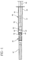
- Fig. 1 is a side-elevational view of the fluid transfer device attached to a syringe.
- Fig. 2 is an exploded view of the fluid transfer device and a syringe barrel.
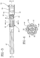
- Fig. 3 is an enlarged side-elevation view of the fluid transfer device.
- Fig. 4 is a cross-sectional view of the fluid transfer device of Fig. 3 taken along line 4-4.
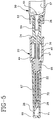
- Fig. 5 is a cross-sectional view of the fluid transfer device of Fig. 3 taken along line 5-5.
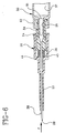
- Fig. 6 is a fluid transfer device of Fig. 5 further illustrating the cutting edge of the access cannula protruding from the distal end of the blunt cannula.
- Fig. 7 is a side-elevational view of the fluid transfer device and syringe being used to draw liquid from a stoppered vial.
- Fig. 8 is a side-elevational view illustrating the fluid transfer device and syringe being used to inject liquid into an injection site of an I.V. set.
-
- While this invention is satisfied by embodiments in many different forms, there are shown in the drawings and will be herein described in detail a preferred embodiment of the invention with the understanding that the present disclosure is to be considered exemplary of the principals of the invention and not intended to limit the scope of the invention to the embodiment illustrated. The scope of the invention will be measured by the appended claims and their equivalents.
- Referring to Figs. 1-8, a
fluid transfer device 20 includes anaccess cannula assembly 21 including anaccess cannula 22 having aproximal end 23, adistal end 25, and a lumen therethrough. Acutting edge 28 is provided at the distal end of the access cannula for piercing a vial stopper or a pierceable septum of an I.V. set injection site. Ahub 29 having an openproximal end 31 and adistal end 32 which is joined to the proximal end of the access cannula so that the lumen of the access cannula is in fluid communication with the open proximal end of the hub. - A
blunt cannula assembly 33 includes ablunt cannula 34 having an openproximal end 35, a bluntdistal end 37, and apassageway 38 therethrough. Ahousing 40 includes an openproximal end 41 and adistal end 43 joined to the proximal end of the blunt cannula. Although the blunt cannula assembly can be made by joining a separate housing and blunt cannula in this embodiment is preferably integrally formed of thermoplastic material having a one-piece construction. The vial access cannula assembly and the blunt cannula assembly are positioned in a concentric relationship wherein a portion ofaccess cannula 22 is within thepassageway 38 of the blunt cannula. - A
spring 45 is positioned betweenhub 29 andhousing 40 for helping to positionaccess cannula 22 withinpassageway 38 ofblunt cannula 34 wherein a proximally directed axial force F, as illustrated in Fig. 6, applied to the blunt cannula will causespring 45 to deflect and cuttingedge 28 ofaccess cannula 22 to project distally outwardly past bluntdistal end 37 of the blunt cannula.Spring 45 in this embodiment is preferably made of elastic material such as natural rubber, synthetic rubber or thermoplastic elastomer.Spring 45 includes alongitudinal conduit 46 which allows it to be slidably placed overaccess cannula 22 and trapped betweenhub 29 andhousing 40. The spring may also be a coil spring similarly placed or placed elsewhere such as adjacent to the access cannula rather than around the access cannula. The spring can also be constructed of cantilever elements projecting to or from the housing or the hub so that the cantilever elements are deflected upon axial movement of the housing toward the hub. The spring element may also be placed around the periphery of the hub, for example, betweenprojections 30 on the hub and the proximal end of the housing. - The fluid transfer device of the present invention also preferably includes means for sealing the access cannula assembly and the blunt cannula assembly so that pressurized liquid passing distally through the access cannula will exit said fluid transfer device through the distal end of the blunt cannula. The means for sealing helps assure that liquid intended for delivery from the blunt distal end of the blunt cannula does not exit the fluid transfer device in other areas. For example, moving through the space between the outside surface of the access cannula and the passageway of the blunt cannula to escape through the space between the hub and the housing. Means for sealing can be accomplished by making the access cannula large enough to substantially occlude the passageway of the blunt cannula to help prevent liquid from passing between the outside of the cannula and the inside of the passageway. Sealing means can also be accomplished by placing a resilient sealing element such as an O-ring or molded annular flange which can seal the space between the access cannula assembly and the blunt cannula assembly. In this preferred embodiment,
spring 45 also functions as a sealing means. In particular,spring 45 is an elastomeric cylindrically shaped element which fits aroundcannula 22 and is slightly compressed when the fluid transfer device is in its resting position so thatdistal end 47 of the spring seals the periphery ofcannula 22 andannular edge 44 in the housing to resist the passage of liquid in a proximal direction from the space between the outside of the access cannula and the passageway of the blunt cannula. The elastomeric element can preferably seal the space between the cannula and the housing or between the hub and the housing or both. - In this embodiment the access cannula assembly preferably includes
access cannula 22 being formed of metal such as stainless steel andhub 29 being formed of a thermoplastic material with the components being joined together by various means including epoxy adhesive. The use of a metal cannula allows a small outside diameter while still maintaining considerable strength. Also, the dimensions and tolerances of the outside diameter of the metal cannula can be closely held for slidable engagement withinpassageway 38 of the blunt cannula to help function as sealing means as described hereinabove. Also, the high strength and reduced diameter of a metal cannula helps reduce penetration forces as the cannula enters a vial stopper or pierceable septum. It is also within the purview of the instant invention to have an access cannula assembly wherein the cannula and the hub are integrally formed of a single material such as thermoplastic. - The fluid transfer device is suitable for use with fluid delivery devices such as syringes. For the purpose of illustration,
fluid transfer device 20 is connected to asyringe 50 comprising asyringe barrel 51 having adistal end 52, an openproximal end 53 and acircular side wall 55 defining achamber 57 for retaining fluid.Volume measuring indicia 58 are on the barrel for measuring the volume of liquid to be delivered. The distal end of the syringe barrel is connected tohub 29 so that the lumen ofaccess cannula 22 is in fluid communication withchamber 57 of the syringe barrel. In this embodiment,distal end 52 of the syringe barrel includes a frusto-conically shapedtip 59 which engages at frusto-conically shapedsurface 26 in openproximal end 31 of the hub. The distal end of the syringe barrel also preferably, but not necessarily, includes a locking luer-type collar 62 concentrically surroundingtip 59. The luer collar has aninternal thread 63 which engagesradial projections 30 onhub 29 to hold the hub securely to the barrel. It is within the scope of the present invention to include various hub configurations to attach to a variety of other medical fluid handling devices. The hub configuration described hereinabove, having a frusto-conically shaped interior cavity, reflects one of these many possibilities. Many syringes and fluid handling devices, such as stopcocks and adapters, and other fluid handling devices contain luer slip and locking luer-type fittings to which a hub having a frusto-conically shaped interior cavity will properly engage. It is within the purview of the present invention to provide a fluid transfer device wherein the hub of the access cannula assembly is integrally molded with the syringe barrel. - A
stopper 64 is positioned inchamber 57 in sliding fluid-tight engagement withcircular side wall 55. A rigidelongate plunger rod 65 is connected to the stopper and extends proximally through the open proximal end ofbarrel 51. The stopper and the plunger rod can be made of one-piece unitary construction. Force applied to the plunger rod causing sliding movement of the stopper in a proximal direction draws fluid throughconduit 61 intochamber 57. Conversely, sliding movement ofstopper 64 in a distal direction urges fluid fromchamber 57 throughconduit 61. -
Fluid transfer device 20 preferably, but not necessary, includes aremovable shield 67 having an openproximal end 68, adistal end 69 and aside wall 70 therebetween defining arecess 71 in the shield. The shield is removably connected to the fluid transfer device so thatblunt cannula 34 is contained withinrecess 71 of the shield. The shield helps protect the blunt cannula from contamination before use. In this embodiment the shield preferably frictionally engageshousing 40 of the blunt cannula assembly. However, it is within the purview of the present invention to provide a shield which engages the hub of the access cannula. - When connecting
fluid transfer device 20 to a syringe such assyringe 50 having a locking luer-type collar the fluid transfer device is rotated to advanceprojections 30 onhub 29 alonginternal thread 63 ofcollar 62. The rotation will pull the hub toward the syringe barrel tightly engagingtip 59 of the syringe barrel into the open proximal end ofhub 29. Because of the torque required to engage the fluid transfer device and a syringe barrel having a locking luer-type collar it is desirable to have torque transmitting means for allowing rotational force applied to the housing of the blunt cannula to be transmitted to the hub of the access cannula assembly so that the user has a larger surface to manually apply rotational forces to the fluid transfer device and such forces are effectively transmitted to the hub. In this embodiment torque transmitting means includes one or more protuberances on the hub such asaxial ribs 39 which engage a slot inhousing 40 formed byaxial projections 24 as best illustrated in Fig. 4. Any combination of protuberances and/or recesses on the hub or housing which are capable of transmitting sufficient torque to engage the hub to the syringe barrel are satisfactory for functioning as torque transmitting means. - It is also preferred to have structure for connecting the hub and the housing to prevent the blunt cannula assembly from being separated from the access cannula assembly and with certain spring configurations, to keep the spring under a slight compressive force, especially when the spring is also being used as sealing means. In this embodiment,
barrier wall 36 at the distal end ofhub 29 engageslongitudinal ribs 24 to help prevent separation of the blunt cannula assembly and the access cannula assembly. These components must be configured to allow the longitudinal ribs to snap over the barrier wall during assembly of the fluid transfer device. -
Fluid transfer device 20, coupled with a fluid delivery device, such assyringe 50 can be used to access fluid in a vial having a pierceable stopper and deliver the fluid to an injection site on an I.V. set or catheter regardless of whether the injection site has a pre-slit septum or a pierceable septum. This is a major advantage of the present invention. No longer are multiple devices needed to fill a syringe from a stoppered vial and deliver the liquid or other medication through an I.V. injection site having a pre-slit septum. The instant invention contains a blunt cannula and an access cannula having a cutting edge at its distal end which is sharp enough to pierce rubber stoppers and septums but does not have to be and is preferably not sharp enough for injection through the skin. Accordingly, there will be less chance to pierce the skin with a dull cutting edge suitable for vial stopper piercing but not for skin injection. - As best illustrated in Fig. 7 the fluid transfer device can be used with
syringe 50 to access injectable liquid or medication, such asfluid 73, contained withinvial 74 having apierceable stopper 75. The fluid is accessed by placing the blunt distal end of the blunt cannula ontop surface 76 ofstopper 75 and applying an axial force through the syringe barrel in direction A. Because the blunt cannula cannot pierce the vial stopper, the top surface of the vial stopper responding with an equal and opposite force to force A, will push the blunt cannula assembly axially proximally towardhub 29 causing the spring to compress and cuttingedge 28 of the access cannula to protrude outwardly from the distal end of the blunt cannula and pierce thestopper 75. When force A is discontinued the cutting edge will, by action of the spring, retract back into the passageway of the blunt cannula. At this point, liquid can be drawn into the syringe barrel using known methods such as the method described hereinabove. The fluid transfer device is then withdrawn from the stopper of the vial. - The filled
syringe 50 withfluid access device 20 attached is now transferred to the point of use where it can be used to inject fluid into a patient through an I.V. set or a catheter having an injection site with a pre-slit or pierceable septum. Specifically, as illustrated in Fig. 8, an I.V. set 80 can include a ahousing 81 having a hollowinterior conduit 82 and aflexible tube 83 connected to the vascular system of a patient, usually through a catheter.Housing 81 also includes anotherflexible tube 85 which is connected to a source of I.V. fluid.Housing 81 also includesport 86 having aconduit 87 therethrough in communication with theinterior conduit 82. Apre-slit septum 88 covers the open end ofconduit 87. The most common ports are covered by pierceable septums or pre-slit septums and are known in the art and sometimes referred to as "PRN" from the Latin pro re nata meaning "as the need arises".Septum 88 is a pre-slit septum having aslit 89 therein.Septum 88 effectively sealsconduit 87 from the exterior of the housing. However, access to the conduit can be achieved by pressing bluntdistal end 37 ofblunt cannula 34 against the area of theseptum containing slit 89. General force applied to the syringe in an axial direction will cause the blunt end of the cannula to enter the conduit through the slit which is forced open by the blunt cannula. Preferably, the force required to open the slit is less than the force required to compress the spring and allow the cutting edge of the access cannula to protrude from the distal end of the blunt cannula. The liquid may now be injected into the I.V. set. Upon completion and removal of the blunt cannula from the conduit, the slit portion of the septum automatically reseals itself. If the septum on the port of the I.V. set is not pre-slit. The fluid access device of the present invention can be used in the same manner as it is used with a pre-slit septum. However, the greater force required to penetrate a pierceable, non-pre-slit septum will cause the spring to compress and the cutting edge of the access cannula to protrude beyond the distal end of the blunt cannula to pierce the septum in a similar manner as when the fluid transfer device is used to pierce the pierceable stopper of the medication vial. The fluid access device of the present invention effectively seals itself so that fluid may be injected through the access cannula or through the blunt cannula, and the cutting edge of the access cannula may be exposed solely by axial proximally directed force exerted on the distal end of the blunt cannula. When the axial force is discontinued the blunt cannula assembly will return to a position wherein the cutting edge of the access cannula is contained within the passageway of the blunt cannula. All relative motions are generally axial and prompted by forces transmitted through the distal end of the blunt cannula.
Claims (1)
- A method for transferring an injectable liquid comprising the steps of:characterized by applying a proximally directed axial force to said blunt cannula to cause said spring means (45) to deflect and said cutting edge (28) of said access cannula to project distally outwardly past the distal end of said blunt cannula;providing syringe (50) including a syringe barrel (51) having an elongate cylindrical body defining a chamber (57) for retaining fluid, an open proximal end (53), a distal end (52) and a tip (59) extending from said distal end having a tip passageway (61) therethrough in fluid communication with said chamber (57), a stopper (64) in fluid-tight slidable engagement inside said barrel and an elongate plunger rod (65) extending proximally from said stopper through said open proximal end of said barrel;providing a fluid transfer device (20) including an access cannula assembly (21) including an access cannula (22) having a proximal end (23), a distal end (25), and a lumen therethrough, a cutting edge (28) at said distal end of said access cannula for piercing a vial stopper, and a hub (29) having an open proximal end (31) and a distal end (32) joined to said proximal end of said access cannula so that said lumen is in fluid communication with said open proximal end of said hub, a blunt cannula assembly (33) including a blunt cannula (34) having a proximal end (35), a blunt distal end (37), and a passageway (38) therethrough, and a housing (40) having an open proximal end (41) and a distal end (43) joined to said proximal end of said blunt cannula, spring means (45) for helping to position said access cannula (22) within said passageway (38) of said blunt cannula (34); and means for sealing said access cannula assembly (21) and said blunt cannula assembly (33) so that pressurized liquid passing distally through said access cannula (22) will exit said fluid transfer device through said distal end (37) of said blunt cannula;
connecting said fluid transfer device (20) to said syringe (50) so that said tip (59) is positioned within said open proximal end (38) of said hub (29) and said chamber (57) is in fluid communication with said lumen of said access cannula (22) ;
providing a vial (74) having a pierceable stopper (75) and containing an injectable liquid (73);
placing said blunt distal end (37) of said blunt cannula (34) in contact with said pierceable stopper (75);
moving said syringe barrel (51) toward said stopper (75) causing said spring (45) to deflect and move said blunt cannula assembly (33) proximally and causing said cutting edge (28) on said distal end of said access cannula (22) to pierce said pierceable stopper to establish fluid communication between the interior of said vial and the chamber of said syringe;
withdrawing the desired amount of injectable liquid (73) from said vial (74) into said chamber (57) by moving said plunger rod (65) in a proximal direction with respect to said barrel (51); and
withdrawing said access cannula (22) from said stopper (75) of said vial (74).
Applications Claiming Priority (2)
| Application Number | Priority Date | Filing Date | Title |
|---|---|---|---|
| US885657 | 1997-06-30 | ||
| US08/885,657 US5755696A (en) | 1997-06-30 | 1997-06-30 | Syringe filling and delivery device |
Publications (3)
| Publication Number | Publication Date |
|---|---|
| EP0888794A2 EP0888794A2 (en) | 1999-01-07 |
| EP0888794A3 EP0888794A3 (en) | 1999-12-08 |
| EP0888794B1 true EP0888794B1 (en) | 2004-11-10 |
Family
ID=25387414
Family Applications (1)
| Application Number | Title | Priority Date | Filing Date |
|---|---|---|---|
| EP98109306A Expired - Lifetime EP0888794B1 (en) | 1997-06-30 | 1998-05-22 | Method for filling syringes |
Country Status (4)
| Country | Link |
|---|---|
| US (1) | US5755696A (en) |
| EP (1) | EP0888794B1 (en) |
| CA (1) | CA2221434C (en) |
| DE (1) | DE69827434T2 (en) |
Families Citing this family (95)
| Publication number | Priority date | Publication date | Assignee | Title |
|---|---|---|---|---|
| IL114960A0 (en) | 1995-03-20 | 1995-12-08 | Medimop Medical Projects Ltd | Flow control device |
| US5928215A (en) * | 1997-08-14 | 1999-07-27 | Becton, Dickinson And Acompany | Syringe filling and delivery device |
| US6610042B2 (en) | 1997-12-05 | 2003-08-26 | Felton Medical, Inc. | Disposable unit-dose jet-injection syringe for pre-filled and/or transfilled liquid injectable medical drug or vaccine products and method thereof |
| US6585701B1 (en) * | 1998-06-15 | 2003-07-01 | Edward D. Dysarz | Trap in modular hub chamber spring needle cannula |
| US7074210B2 (en) * | 1999-10-11 | 2006-07-11 | Felton International, Inc. | Universal protector cap with auto-disable features for needle-free injectors |
| EP1220697B1 (en) | 1999-10-11 | 2004-12-29 | Felton International, Inc. | Universal anti-infectious protector for needleless injectors |
| US6517516B1 (en) * | 1999-10-15 | 2003-02-11 | Becton Dickinson And Company | Method of making a retracting needle syringe |
| US7887506B1 (en) | 1999-11-23 | 2011-02-15 | Pulse Needlefree Systems, Inc. | Safety mechanism to prevent accidental patient injection and methods of same |
| US6770054B1 (en) | 1999-11-23 | 2004-08-03 | Felton International, Inc. | Injector assembly with driving means and locking means |
| US6712787B1 (en) | 2000-05-19 | 2004-03-30 | Edward D. Dysarz | Self destructive safety syringe |
| US6533759B1 (en) * | 2000-06-01 | 2003-03-18 | Robert Watson | Flash chamber with a self closing valve for use with a catheter |
| US6629958B1 (en) | 2000-06-07 | 2003-10-07 | Ronald P. Spinello | Leak sealing needle |
| US6685693B1 (en) | 2000-08-09 | 2004-02-03 | J. Michael Casso | Method of preparing a syringe for injection |
| US6685677B2 (en) * | 2000-09-07 | 2004-02-03 | Christopher H. Green | Needle shield converting to a needleless needle |
| WO2003095002A1 (en) * | 2001-01-24 | 2003-11-20 | North American Medical Products, Inc. | Spring-loaded needle protective assembly for multi-draw needle |
| US6908459B2 (en) | 2001-12-07 | 2005-06-21 | Becton, Dickinson And Company | Needleless luer access connector |
| TW200406829A (en) * | 2002-09-17 | 2004-05-01 | Adv Lcd Tech Dev Ct Co Ltd | Interconnect, interconnect forming method, thin film transistor, and display device |
| AU2003275607A1 (en) * | 2002-10-24 | 2004-05-13 | Terumo Kabushiki Kaisha | Method of producing syringe, cap, and prefilled syringe |
| EP1558311B1 (en) * | 2003-02-11 | 2006-12-06 | Salvus Technology Limited | A safety needle |
| IL161660A0 (en) | 2004-04-29 | 2004-09-27 | Medimop Medical Projects Ltd | Liquid drug delivery device |
| SE0401569D0 (en) * | 2004-06-17 | 2004-06-17 | Gambro Lundia Ab | applicator |
| WO2006082350A1 (en) * | 2005-02-03 | 2006-08-10 | Salvus Technology Ltd | A safety needle |
| US8827961B2 (en) * | 2005-02-03 | 2014-09-09 | West Pharmaceutical Services, Inc. | Safety needle |
| US8597255B2 (en) * | 2005-02-03 | 2013-12-03 | Salvus Technology Limited | Safety needle |
| WO2006090118A1 (en) * | 2005-02-25 | 2006-08-31 | Salvus Technology Limited | Safety needle accessory |
| US8540686B2 (en) * | 2005-03-02 | 2013-09-24 | Covidien Ag | Blunt tip vial access cannula |
| JP5179350B2 (en) | 2005-05-06 | 2013-04-10 | インストゥルメンテーション ラボラトリー カンパニー | Nested closed tube sampling assembly |
| US8070739B2 (en) | 2005-08-11 | 2011-12-06 | Medimop Medical Projects Ltd. | Liquid drug transfer devices for failsafe correct snap fitting onto medicinal vials |
| US8313476B2 (en) * | 2006-06-14 | 2012-11-20 | Dionex Corporation | Sampling needle and methods of forming and using same |
| IL182605A0 (en) | 2007-04-17 | 2007-07-24 | Medimop Medical Projects Ltd | Fluid control device with manually depressed actuator |
| CA2684744C (en) * | 2007-04-26 | 2016-06-21 | Tyco Healthcare Group Lp | Multifunctional medical access device |
| WO2009038860A2 (en) | 2007-09-18 | 2009-03-26 | Medeq Llc | Medicament mixing and injection apparatus |
| IL186290A0 (en) | 2007-09-25 | 2008-01-20 | Medimop Medical Projects Ltd | Liquid drug delivery devices for use with syringe having widened distal tip |
| GB0719876D0 (en) * | 2007-10-11 | 2007-11-21 | Weston Terence E | Safety needle |
| US7981089B2 (en) * | 2008-03-31 | 2011-07-19 | Tyco Healthcare Group Lp | Vial access device |
| US8382722B2 (en) * | 2008-06-30 | 2013-02-26 | Covidien Lp | Blunt tip vial access cannula and method for manufacture |
| USD641080S1 (en) | 2009-03-31 | 2011-07-05 | Medimop Medical Projects Ltd. | Medical device having syringe port with locking mechanism |
| CA2921304C (en) | 2009-07-30 | 2018-06-05 | Tandem Diabetes Care, Inc. | Infusion pump system with disposable cartridge having pressure venting and pressure feedback |
| USD630732S1 (en) | 2009-09-29 | 2011-01-11 | Medimop Medical Projects Ltd. | Vial adapter with female connector |
| IL201323A0 (en) | 2009-10-01 | 2010-05-31 | Medimop Medical Projects Ltd | Fluid transfer device for assembling a vial with pre-attached female connector |
| IL202070A0 (en) | 2009-11-12 | 2010-06-16 | Medimop Medical Projects Ltd | Inline liquid drug medical device |
| IL202069A0 (en) | 2009-11-12 | 2010-06-16 | Medimop Medical Projects Ltd | Fluid transfer device with sealing arrangement |
| BR112012020829B1 (en) | 2010-02-24 | 2020-04-14 | Medimop Medical Projects Ltd | liquid drug transfer device for use with a medical bottle |
| CN102711712B (en) | 2010-02-24 | 2014-08-13 | 麦迪麦珀医疗工程有限公司 | Fluid transfer assembly with venting arrangement |
| USD669980S1 (en) | 2010-10-15 | 2012-10-30 | Medimop Medical Projects Ltd. | Vented vial adapter |
| IL209290A0 (en) | 2010-11-14 | 2011-01-31 | Medimop Medical Projects Ltd | Inline liquid drug medical device having rotary flow control member |
| IL212420A0 (en) | 2011-04-17 | 2011-06-30 | Medimop Medical Projects Ltd | Liquid drug transfer assembly |
| US9125992B2 (en) | 2011-09-16 | 2015-09-08 | Melvin A. Finke | Fluid delivery device with filtration |
| US8945087B2 (en) | 2011-09-30 | 2015-02-03 | Covidien Lp | Pre-pierced IV access port |
| IL215699A0 (en) | 2011-10-11 | 2011-12-29 | Medimop Medical Projects Ltd | Liquid drug reconstitution assemblage for use with iv bag and drug vial |
| USD720451S1 (en) | 2012-02-13 | 2014-12-30 | Medimop Medical Projects Ltd. | Liquid drug transfer assembly |
| USD674088S1 (en) | 2012-02-13 | 2013-01-08 | Medimop Medical Projects Ltd. | Vial adapter |
| USD737436S1 (en) | 2012-02-13 | 2015-08-25 | Medimop Medical Projects Ltd. | Liquid drug reconstitution assembly |
| IL219065A0 (en) | 2012-04-05 | 2012-07-31 | Medimop Medical Projects Ltd | Fluid transfer device with manual operated cartridge release arrangement |
| US9180242B2 (en) | 2012-05-17 | 2015-11-10 | Tandem Diabetes Care, Inc. | Methods and devices for multiple fluid transfer |
| IL221635A0 (en) | 2012-08-26 | 2012-12-31 | Medimop Medical Projects Ltd | Drug vial mixing and transfer device for use with iv bag and drug vial |
| IL221634A0 (en) | 2012-08-26 | 2012-12-31 | Medimop Medical Projects Ltd | Universal drug vial adapter |
| JP5868555B2 (en) | 2012-09-13 | 2016-02-24 | メディモップ・メディカル・プロジェクツ・リミテッド | Nested female vial adapter |
| USD734868S1 (en) | 2012-11-27 | 2015-07-21 | Medimop Medical Projects Ltd. | Drug vial adapter with downwardly depending stopper |
| US9173998B2 (en) | 2013-03-14 | 2015-11-03 | Tandem Diabetes Care, Inc. | System and method for detecting occlusions in an infusion pump |
| IL225734A0 (en) | 2013-04-14 | 2013-09-30 | Medimop Medical Projects Ltd | Ready-to-use drug vial assemblages including drug vial and drug vial closure having fluid transfer member, and drug vial closure therefor |
| DK2983745T3 (en) | 2013-05-10 | 2018-10-22 | West Pharma Services Il Ltd | Medical devices comprising ampoule adapter with interconnected module for dry drug |
| CN205626622U (en) | 2013-08-07 | 2016-10-12 | 麦迪麦珀医疗工程有限公司 | Liquid transfer device that is used together with infusion container |
| USD767124S1 (en) | 2013-08-07 | 2016-09-20 | Medimop Medical Projects Ltd. | Liquid transfer device with integral vial adapter |
| USD765837S1 (en) | 2013-08-07 | 2016-09-06 | Medimop Medical Projects Ltd. | Liquid transfer device with integral vial adapter |
| EP2893916B1 (en) | 2014-01-14 | 2016-04-13 | Tim Plastik ve Kalip Teknolojileri Endustri ve Tic. A.S. | Fluid transfer device having a piercing member |
| USD757933S1 (en) | 2014-09-11 | 2016-05-31 | Medimop Medical Projects Ltd. | Dual vial adapter assemblage |
| JP6358724B2 (en) | 2015-01-05 | 2018-07-18 | ウエスト・ファーマ.サービシーズ・イスラエル,リミテッド | Dual vial adapter assembly with easy removable pill adapter to ensure accurate use |
| USD765838S1 (en) | 2015-03-26 | 2016-09-06 | Tech Group Europe Limited | Syringe retention clip |
| US20170014579A1 (en) * | 2015-07-14 | 2017-01-19 | Smiths Medical Asd, Inc. | Blunt cannula needle device |
| CN113143759B (en) | 2015-07-16 | 2024-01-30 | 西部制药服务以色列有限公司 | Liquid drug transfer device for secure telescopic snap-fit on an injection vial |
| USD801522S1 (en) | 2015-11-09 | 2017-10-31 | Medimop Medical Projects Ltd. | Fluid transfer assembly |
| BR112018010435B1 (en) | 2015-11-25 | 2022-06-28 | West Pharma. Services IL, Ltd. | DOUBLE AMPOULE ADAPTER SET FOR USE WITH A SYRINGE WITHOUT NEEDLE WITH A MALE CONNECTOR, A DRUG AMPOULE AND A LIQUID AMPOULE |
| IL245800A0 (en) | 2016-05-24 | 2016-08-31 | West Pharma Services Il Ltd | Dual vial adapter assemblages including identical twin vial adapters |
| IL245803A0 (en) | 2016-05-24 | 2016-08-31 | West Pharma Services Il Ltd | Dual vial adapter assemblages including vented drug vial adapter and vented liquid vial adapter |
| IL246073A0 (en) | 2016-06-06 | 2016-08-31 | West Pharma Services Il Ltd | Fluid transfer devices for use with drug pump cartridge having slidable driving plunger |
| IL247376A0 (en) | 2016-08-21 | 2016-12-29 | Medimop Medical Projects Ltd | Syringe assembly |
| TWI637756B (en) * | 2016-10-13 | 2018-10-11 | 怡安醫療器材股份有限公司 | Pressure controller for phlegm sucking device |
| USD832430S1 (en) | 2016-11-15 | 2018-10-30 | West Pharma. Services IL, Ltd. | Dual vial adapter assemblage |
| IL249408A0 (en) | 2016-12-06 | 2017-03-30 | Medimop Medical Projects Ltd | Liquid transfer device for use with infusion liquid container and pincers-like hand tool for use therewith for releasing intact drug vial therefrom |
| US10918801B2 (en) * | 2016-12-13 | 2021-02-16 | Becton, Dickinson And Company | Caps for integrated fill and inject of safety needle devices |
| IL251458A0 (en) | 2017-03-29 | 2017-06-29 | Medimop Medical Projects Ltd | User actuated liquid drug transfer devices for use in ready-to-use (rtu) liquid drug transfer assemblages |
| IL254802A0 (en) | 2017-09-29 | 2017-12-31 | Medimop Medical Projects Ltd | Dual vial adapter assemblages with twin vented female vial adapters |
| US11083847B2 (en) | 2018-01-26 | 2021-08-10 | Becton, Dickinson And Company | Flush syringe with flip cap |
| BR112020015242A2 (en) | 2018-01-30 | 2021-01-26 | Becton, Dickinson And Company | universal connector or cap for fittings with male and female threads |
| US11273298B2 (en) | 2018-04-10 | 2022-03-15 | Becton, Dickinson And Company | Universal single-use cap for male and female connectors |
| JP1630477S (en) | 2018-07-06 | 2019-05-07 | ||
| USD923812S1 (en) | 2019-01-16 | 2021-06-29 | West Pharma. Services IL, Ltd. | Medication mixing apparatus |
| JP1648075S (en) | 2019-01-17 | 2019-12-16 | ||
| US11511100B2 (en) | 2019-01-30 | 2022-11-29 | Becton, Dickinson And Company | Universal cap for male and female connectors |
| PT3917486T (en) | 2019-01-31 | 2023-05-08 | West Pharma Services Il Ltd | Liquid transfer device |
| EP4360670A2 (en) | 2019-04-30 | 2024-05-01 | West Pharma Services IL, Ltd | Liquid transfer device with dual lumen iv spike |
| US11890445B2 (en) | 2019-12-23 | 2024-02-06 | Becton, Dickinson And Company | Universal disinfection cap |
| US11890446B2 (en) | 2020-04-17 | 2024-02-06 | Becton, Dickinson And Company | Cap for male and female threaded fittings |
| USD956958S1 (en) | 2020-07-13 | 2022-07-05 | West Pharma. Services IL, Ltd. | Liquid transfer device |
Family Cites Families (20)
| Publication number | Priority date | Publication date | Assignee | Title |
|---|---|---|---|---|
| US2389355A (en) * | 1943-01-27 | 1945-11-20 | Goland | Surgical needle |
| US3662754A (en) * | 1970-05-04 | 1972-05-16 | William X Halloran | Injection apparatus |
| US4139009A (en) * | 1976-11-23 | 1979-02-13 | Marcial Alvarez | Hypodermic needle assembly with retractable needle cover |
| US5411499A (en) * | 1988-01-25 | 1995-05-02 | Baxter International Inc. | Needleless vial access device |
| US4850996A (en) * | 1988-02-22 | 1989-07-25 | Cree Ian C | Safety needle |
| US4846809A (en) * | 1988-02-29 | 1989-07-11 | Winifred Sims | Needle tip protective device |
| US4846804A (en) * | 1988-03-24 | 1989-07-11 | Dlp Inc. | Combined needle protector and guidewire feeder |
| US4906236A (en) * | 1988-08-29 | 1990-03-06 | Alberts David S | Self-sheathing hypodermic needle |
| US5407431A (en) * | 1989-07-11 | 1995-04-18 | Med-Design Inc. | Intravenous catheter insertion device with retractable needle |
| US4998922A (en) * | 1990-02-23 | 1991-03-12 | Kuracina Thomas C | Safety syringe cap minimizing needle-stick probability |
| US5360408A (en) * | 1992-11-16 | 1994-11-01 | Vaillancourt Vincent L | Shielded hypodermic needle assembly and a shield assembly for a hypodermic needle |
| US5472430A (en) * | 1993-08-18 | 1995-12-05 | Vlv Associates | Protected needle assembly |
| ITSS930002U1 (en) * | 1993-09-16 | 1995-03-16 | Antonio Giovanni Flumene | INTRAVENESE CATHETER WITH AUTOMATIC DISAPPEARANCE OF THE GUIDE NEEDLE IN A PROTECTIVE HOOD. |
| US5425718A (en) * | 1993-10-22 | 1995-06-20 | Tay; Sew-Wah | Self-sticking needle assembly and method for insertion into an artery |
| EP0657184B1 (en) * | 1993-12-10 | 2001-11-07 | The BOC Group plc | Medical device |
| US5573510A (en) * | 1994-02-28 | 1996-11-12 | Isaacson; Dennis R. | Safety intravenous catheter assembly with automatically retractable needle |
| US5609584A (en) * | 1994-05-18 | 1997-03-11 | Gettig Technologies, Inc. | Adaptor system for use with a syringe |
| US5549568A (en) * | 1994-08-22 | 1996-08-27 | Shields; Jack W. | Elastomeric needle shield and hub-cap |
| US5584819A (en) * | 1995-03-13 | 1996-12-17 | Kopfer; Rudolph J. | Nested blunt/sharp injection assembly |
| US5549558A (en) * | 1995-06-09 | 1996-08-27 | Martin; Robin P. | Self sheathing safety needle |
-
1997
- 1997-06-30 US US08/885,657 patent/US5755696A/en not_active Expired - Lifetime
- 1997-11-18 CA CA002221434A patent/CA2221434C/en not_active Expired - Lifetime
-
1998
- 1998-05-22 EP EP98109306A patent/EP0888794B1/en not_active Expired - Lifetime
- 1998-05-22 DE DE69827434T patent/DE69827434T2/en not_active Expired - Fee Related
Also Published As
| Publication number | Publication date |
|---|---|
| US5755696A (en) | 1998-05-26 |
| DE69827434T2 (en) | 2005-11-24 |
| DE69827434D1 (en) | 2004-12-16 |
| CA2221434C (en) | 2001-04-17 |
| EP0888794A2 (en) | 1999-01-07 |
| EP0888794A3 (en) | 1999-12-08 |
| CA2221434A1 (en) | 1998-12-30 |
Similar Documents
| Publication | Publication Date | Title |
|---|---|---|
| EP0888794B1 (en) | Method for filling syringes | |
| US5746733A (en) | Syringe filling and delivery device | |
| US5832971A (en) | Syringe filling and delivery device | |
| US4599082A (en) | Two-component syringe assembly | |
| EP0873757B1 (en) | Cannula sealing shield assembly | |
| US5807374A (en) | Syringe filling and delivery device | |
| JP4216466B2 (en) | Fluid transfer assembly | |
| US4932944A (en) | Intravenous port injection and connector system | |
| US6958055B2 (en) | Retractable needle syringe including a sheath and an intravenous adapter | |
| US5928215A (en) | Syringe filling and delivery device | |
| US5718690A (en) | Hypodermic injector system and method for maintaining the sterility thereof prior to use | |
| US20020173753A1 (en) | Attachment for a medical device | |
| CN112105328B (en) | Connector for connecting a medical injection device to a container | |
| EP0820779B1 (en) | Syringe filling and delivery device | |
| JP3294537B2 (en) | Fluid transfer device for accessing fluid from vials and ampules and method for transferring fluid using the device | |
| WO2017011164A1 (en) | Blunt cannula needle device | |
| US20220218909A1 (en) | Syringe Assembly | |
| EP4041343A1 (en) | Connector for connecting a medical injection device to a container and assembly comprising said connector and medical injection device | |
| WO2004043514A2 (en) | Pre-filled retractable needle injection device | |
| MXPA97005521A (en) | Filling and supply device of jeri |
Legal Events
| Date | Code | Title | Description |
|---|---|---|---|
| PUAI | Public reference made under article 153(3) epc to a published international application that has entered the european phase |
Free format text: ORIGINAL CODE: 0009012 |
|
| AK | Designated contracting states |
Kind code of ref document: A2 Designated state(s): DE FR GB IT |
|
| AX | Request for extension of the european patent |
Free format text: AL;LT;LV;MK;RO;SI |
|
| PUAL | Search report despatched |
Free format text: ORIGINAL CODE: 0009013 |
|
| AK | Designated contracting states |
Kind code of ref document: A3 Designated state(s): AT BE CH CY DE DK ES FI FR GB GR IE IT LI LU MC NL PT SE |
|
| AX | Request for extension of the european patent |
Free format text: AL;LT;LV;MK;RO;SI |
|
| 17P | Request for examination filed |
Effective date: 20000510 |
|
| AKX | Designation fees paid |
Free format text: DE FR GB IT |
|
| 17Q | First examination report despatched |
Effective date: 20030806 |
|
| GRAP | Despatch of communication of intention to grant a patent |
Free format text: ORIGINAL CODE: EPIDOSNIGR1 |
|
| RTI1 | Title (correction) |
Free format text: METHOD FOR FILLING SYRINGES |
|
| GRAS | Grant fee paid |
Free format text: ORIGINAL CODE: EPIDOSNIGR3 |
|
| GRAA | (expected) grant |
Free format text: ORIGINAL CODE: 0009210 |
|
| AK | Designated contracting states |
Kind code of ref document: B1 Designated state(s): DE FR GB IT |
|
| REG | Reference to a national code |
Ref country code: GB Ref legal event code: FG4D |
|
| REF | Corresponds to: |
Ref document number: 69827434 Country of ref document: DE Date of ref document: 20041216 Kind code of ref document: P |
|
| PLBE | No opposition filed within time limit |
Free format text: ORIGINAL CODE: 0009261 |
|
| STAA | Information on the status of an ep patent application or granted ep patent |
Free format text: STATUS: NO OPPOSITION FILED WITHIN TIME LIMIT |
|
| 26N | No opposition filed |
Effective date: 20050811 |
|
| ET | Fr: translation filed | ||
| PGFP | Annual fee paid to national office [announced via postgrant information from national office to epo] |
Ref country code: DE Payment date: 20070702 Year of fee payment: 10 |
|
| PG25 | Lapsed in a contracting state [announced via postgrant information from national office to epo] |
Ref country code: DE Free format text: LAPSE BECAUSE OF NON-PAYMENT OF DUE FEES Effective date: 20081202 |
|
| REG | Reference to a national code |
Ref country code: FR Ref legal event code: PLFP Year of fee payment: 19 |
|
| REG | Reference to a national code |
Ref country code: FR Ref legal event code: PLFP Year of fee payment: 20 |
|
| PGFP | Annual fee paid to national office [announced via postgrant information from national office to epo] |
Ref country code: FR Payment date: 20170421 Year of fee payment: 20 Ref country code: GB Payment date: 20170426 Year of fee payment: 20 |
|
| PGFP | Annual fee paid to national office [announced via postgrant information from national office to epo] |
Ref country code: IT Payment date: 20170421 Year of fee payment: 20 |
|
| REG | Reference to a national code |
Ref country code: GB Ref legal event code: PE20 Expiry date: 20180521 |
|
| PG25 | Lapsed in a contracting state [announced via postgrant information from national office to epo] |
Ref country code: GB Free format text: LAPSE BECAUSE OF EXPIRATION OF PROTECTION Effective date: 20180521 |