EP0889611A1 - Time multiplexing method, and related arrangements to be used in a central station and network terminals of a communications network - Google Patents
Time multiplexing method, and related arrangements to be used in a central station and network terminals of a communications network Download PDFInfo
- Publication number
- EP0889611A1 EP0889611A1 EP97401562A EP97401562A EP0889611A1 EP 0889611 A1 EP0889611 A1 EP 0889611A1 EP 97401562 A EP97401562 A EP 97401562A EP 97401562 A EP97401562 A EP 97401562A EP 0889611 A1 EP0889611 A1 EP 0889611A1
- Authority
- EP
- European Patent Office
- Prior art keywords
- group
- network
- network terminals
- central station
- terminals
- Prior art date
- Legal status (The legal status is an assumption and is not a legal conclusion. Google has not performed a legal analysis and makes no representation as to the accuracy of the status listed.)
- Granted
Links
Images

Classifications
-
- H—ELECTRICITY
- H04—ELECTRIC COMMUNICATION TECHNIQUE
- H04J—MULTIPLEX COMMUNICATION
- H04J3/00—Time-division multiplex systems
- H04J3/16—Time-division multiplex systems in which the time allocation to individual channels within a transmission cycle is variable, e.g. to accommodate varying complexity of signals, to vary number of channels transmitted
- H04J3/1694—Allocation of channels in TDM/TDMA networks, e.g. distributed multiplexers
Definitions
- the present invention relates to a method to assign upstream timeslots to a plurality of network terminals, as defined in the preamble of claim 1, an arrangement to be used in a network terminal to perform this method, as defined in the preamble of claim 5, and an arrangement to be used in a central station to perform this method, as defined in the preamble of claim 10.
- the central station in the optical network of the mentioned proposal is called the OLT (Optical Line Termination), whereas the network terminals are named ONU's (Optical Network Units).
- OLT Optical Line Termination
- ONU's Optical Network Units
- the contents of such a PLOAM cell as proposed by Mark Bridger et al. is shown in a figure on page 4 of the just cited proposal.
- the 30 grant messages therein each contain an ONU identifier.
- Each ONU identified in the PLOAM cell is permitted to occupy one timeslot. By downstream broadcasting this message, all ONU's in the network become aware of the order wherein they are allowed to occupy upstream timeslots for transmission of data bursts towards the OLT.
- the upstream timeslots may be standard full size upstream slots with a length of 56 bytes or short slots with a length of 7 bytes. Schemes of the contents of such a short slot and such a standard full size slot are drawn in the figures on pages 2 and 3 of the proposal.
- the amount of downstream bandwidth needed thereto is that for transmission of a group identifier and may be considered equal to that needed for transmission of a terminal identifier in the known method.
- the downstream bandwidth occupancy to assign an equal amount of timeslots to terminals is reduced with a factor equal to the number of network terminals that composes one group.
- the same amount of bandwidth can be used according to the present invention to assign an increased number of timeslots.
- the number of timeslots that can be assigned has increased by a factor equal to the number of network terminals composing one group.
- the central station when the central station itself composes the groups of terminals, the central station is able to modify the composition of groups whenever this is preferable.
- a terminal When a terminal is de-activated for instance, it is preferred to eliminate this terminal from all groups where it belongs to so that it does not receive any permission anymore to occupy upstream timeslots. It also is preferable to compose a group of most active terminals, so that no timeslot is to be assigned to a little active terminal each time a timeslot is assigned to the most active terminal. Obviously, the composition of this group changes in time.
- composing the groups implicitly via a membership-relation has the advantage that no additional complexity is required in the central station for composing the groups and communicating the composition of the groups to the network terminals.
- composing the groups via a membership-relation has the drawback that the groups are not modifiable.
- any terminal can determine from its own terminal identifier whether it belongs to a group or not if it receives the identifier of this group.
- the terminal does not need to memorize a table of groups where it belongs to. It only has to be aware of the membership-relation between its terminal identifier and the group identifiers of groups where it belongs to.
- a network terminal is aware of the predefined order to be respected by the terminals composing a single group in case this order is not derivable from a membership-relation or any other rule known by the terminal. From the index, the network terminal can determine in which timeslot it is allowed to transmit a burst and from which starting time it is allowed to transmit this burst if the timeslots have fixed lengths. The terminal moreover can keep track of any changes in order between terminals in one group if, for some unspecified reason, this would be preferable.
- Still a further feature of the present invention is defined by claim 8 and claim 13.
- a network terminal is also capable of determining the starting time from which it is allowed to transmit a burst in case the timeslots have variable lengths.
- This is for instance so in the co-pending European Patent Application entitled 'Time Slot Management Method and Main Station and Substation Realizing such a Method and Time Division Multiple Access Network Including such a Main Station and such a Substation', filed at even date by the same applicant.
- the time reference information for instance can be the offset from the start time of an upstream timeslot to the start time of an upstream frame, or the offset of the start time of a short timeslot to the start time of a standard timeslot whereof a short timeslot forms part if only the short timeslots are made modifiable in length
- Still a further feature of the present invention is defined by claim 9 and claim 14.
- the central station can adapt the length of a timeslot assigned to a specific terminal whenever this is desired, and the network terminal is capable of determining the length of the timeslot in which it is allowed to transmit an upstream burst.
- a remark is that the amount of downstream bandwidth gained in comparison with the known method to assign a certain number of timeslots to terminals is proportional to the size of the groups, expressed as the number of network terminals whereof it is composed. This is equivalent to stating that the number of timeslots that can be assigned to network terminals, given a certain downstream bandwidth available, is proportional to this size of the groups. Since however the flexibility of assigning timeslots to network terminals decreases with the size of the groups, there is a trade-off between use of bandwidth and network flexibility which will allow network designers to make a proper choice for the size of the groups.
Abstract
Description
Claims (14)
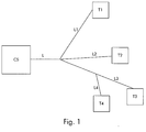
- Method to assign upstream timeslots to a plurality of network terminals (T1, T2, T3, T4) in a communications network wherein a central station (CS) is coupled to said plurality of network terminals (T1, T2, T3, T4) via the cascade connection of a common link (L) and respective individual links (L1, L2, L3, L4) and wherein said network terminals (T1, T2, T3, T4) transmit upstream information to said central station (CS) in a time multiplexed way over said common link (L) using said upstream timeslots,
CHARACTERIZED IN THAT said central station (CS) downstream broadcasts a group identifier (GI2) to assign a plurality of said upstream timeslots in a predefined order to network terminals (T2, T3) of a group (G2) of said plurality of network terminals (T1, T2, T3, T4), said group (G2) having a predefined composition and being identified by said group identifier (GI2). - Method according to claim 1,
CHARACTERIZED IN THAT said composition is predefined by said central station (CS) and communicated from said central station (CS) to said plurality of network terminals (T1, T2, T3, T4). - Method according to claim 1,
CHARACTERIZED IN THAT said composition is predefined implicitly via a membership-relation between said group identifier (GI2) and terminal identifiers (TI2, TI3) of said network terminals (T2, T3) that form part of said group (G2). - Method according to claim 3,
CHARACTERIZED IN THAT said group (G2) is composed of a first network terminal (T2) whose terminal identifier (TI2) equals said group identifier (GI2), and at least one network terminal (T3) with successive terminal identifier (TI3). - Arrangement to be used in a network terminal (T2) of a communications network wherein a central station (CS) is coupled to a plurality of network terminals (T1, T2, T3, T4) via the cascade connection of a common link (L) and respective individual links (L1, L2, L3, L4) and wherein said network terminals (T1, T2, T3, T4) transmit information to said central station (CS) in a time multiplexed way over said common link (L) using upstream timeslots assigned by said central station (CS), said plurality of network terminals (T1, T2, T3, T4) comprising said network terminal (T2),
CHARACTERIZED IN THAT said arrangement comprises:a. comparison means (CMP), adapted to compare a group identifier (GI2), downstream broadcasted by said central station (CS) to assign a plurality of said upstream timeslots in a predefined order to network terminals (T2, T3) of a group (G2) of said plurality of network terminals (T1, T2, T3, T4), said group (G2) being identified by said group identifier (GI2), with group identifiers (GI1, GI2) of groups (G1, G2) of network terminals whereof said network terminal (T2) forms part; andb. control means (CTRL), coupled between said comparison means (CMP) and a transmitting part (TP) of said network terminal (T2) and adapted to control, in case said group identifier (GI2) downstream broadcasted matches one of said group identifiers (GI1, GI2), said transmitting part (TP) to transmit an upstream burst in a thereby assigned upstream timeslot and to respect said predefined order. - Arrangement according to claim 5,
CHARACTERIZED IN THAT said arrangement further comprises:c. memory means (MEM) with an output coupled to an input of said comparison means (CMP), said memory means (MEM) being adapted to memorize said group identifiers (GI1, GI2) of said groups (G1, G2) of network terminals whereof said network terminal (T2) forms part. - Arrangement according to claim 6,
CHARACTERIZED IN THAT said memory means (MEM) further is adapted to memorize for each group (G1, G2) of said groups of network terminals whereof said network terminal (T2) forms part, an index (2, 1) of said network terminal (T2) in said group (G1, G2), i.e. an integer number defining said predefined order for said group (G1, G2). - Arrangement according to claim 6,
CHARACTERIZED IN THAT said memory means (MEM) further is adapted to memorize for each group (G1, G2) of said groups of network terminals where said network terminal (T2) forms part of, time reference information defining the starting time of an upstream timeslot wherein said network terminal (T2) is allowed to send information. - Arrangement according to claim 6,
CHARACTERIZED IN THAT said memory means (MEM) further is adapted to memorize for each group (G1, G2) of said groups of network terminals where said network terminal (T2) forms part of, a timeslot length (7, 7) defining the length of an upstream timeslot wherein said network terminal (T2) is allowed to send information. - Arrangement to be used in a central station (CS) of a communications network wherein said central station (CS) is coupled to a plurality of network terminals (T1, T2, T3, T4) via the cascade connection of a common link (L) and respective individual links (L1, L2, L3, L4) and wherein said network terminals (T1, T2, T3, T4) transmit information to said central station (CS) in a time multiplexed way over said common link (L) using upstream timeslots assigned by said central station (CS),
CHARACTERIZED IN THAT said arrangement comprises:a. selection means (SEL) adapted to select a precomposed group (G2) of network terminals (T2, T3);b. message generating means (MGM), to an input of which said selection means (SEL) is coupled and which is adapted to generate a broadcast message including a group identifier (GI2) of said precomposed group (G2) of network terminals (T2, T3); andc. a transmitting part (TP'), to an input (I2) of which said message generating means (MGM) is coupled, said transmitting part (TP') being adapted to broadcast said broadcast message to said plurality of network terminals (T1, T2, T3, T4) to thereby assign a plurality of said upstream timeslots in a predefined order to said network terminals (T2, T3) of said precomposed group (G2). - Arrangement according to claim 10,
CHARACTERIZED IN THAT said arrangement further comprises:c. grouping means (GRM), adapted to precompose said group (G2) of network terminals (T2, T3) and to assign thereto said group identifier (GI2); andd. communication means (COM), coupled between said grouping means (GRM) and another input (I1) of said transmitting part (TP'), said communication means (COM) being adapted to generate a message containing information with respect to the composition of said precomposed group (G2). - Arrangement according to claim 11,
CHARACTERIZED IN THAT said arrangement further comprises:e. group memory means (GM) adapted to memorize group identifiers (GI1, GI2, GI3, GI4, ...) of precomposed groups (G1, G2, G3, G4, ...) of network terminals similar to said precomposed group (G2), and provided with outputs coupled to inputs of said message generating means (MGM) and said communication means (COM). - Arrangement according to claim 10,
CHARACTERIZED IN THAT said message generating means (MGM) further is adapted to embed in said broadcast message time reference information defining the starting time of said upstream timeslots assigned to said network terminals (T2, T3) of said precomposed group (G2). - Arrangement according to claim 10,
CHARACTERIZED IN THAT said message generating means (MGM) further is adapted to embed in said broadcast message timeslot lengths for said plurality of upstream timeslots assigned to said network terminals (T2, T3) of said precomposed group (G2).
Priority Applications (9)
| Application Number | Priority Date | Filing Date | Title |
|---|---|---|---|
| DE69726845T DE69726845T2 (en) | 1997-07-02 | 1997-07-02 | Time division multiplexing and associated arrangements for use in a central station and network terminals of a communications network |
| ES97401562T ES2208842T3 (en) | 1997-07-02 | 1997-07-02 | Time multiplexing method and RELATED PROVISIONS FOR USE IN A CENTRAL STATION AND IN TERMINALS OF A COMMUNICATION NETWORK. |
| EP97401562A EP0889611B1 (en) | 1997-07-02 | 1997-07-02 | Time multiplexing method, and related arrangements to be used in a central station and network terminals of a communications network |
| AU73149/98A AU737871B2 (en) | 1997-07-02 | 1998-06-25 | Time multiplexing method for a communications network |
| CA002239911A CA2239911A1 (en) | 1997-07-02 | 1998-06-29 | Time multiplexing method and related arrangements to be used in a central station and network terminals of a communications network |
| US09/108,693 US6463075B1 (en) | 1997-07-02 | 1998-07-01 | Time multiplexing method, and related arrangements to be used in a central station and network terminals of a communications network |
| CNB981155839A CN1142643C (en) | 1997-07-02 | 1998-07-02 | Time-division multiplexing method and arrangement for central station and network terminal of communication network |
| JP18792698A JP4057703B2 (en) | 1997-07-02 | 1998-07-02 | Time division multiplexing method and related equipment used in the central station and network terminal of the communication network |
| US10/235,178 US7133413B2 (en) | 1997-07-02 | 2002-09-04 | Time multiplexing method, and related arrangements to be used in a central station and network terminals of a communications network |
Applications Claiming Priority (1)
| Application Number | Priority Date | Filing Date | Title |
|---|---|---|---|
| EP97401562A EP0889611B1 (en) | 1997-07-02 | 1997-07-02 | Time multiplexing method, and related arrangements to be used in a central station and network terminals of a communications network |
Publications (2)
| Publication Number | Publication Date |
|---|---|
| EP0889611A1 true EP0889611A1 (en) | 1999-01-07 |
| EP0889611B1 EP0889611B1 (en) | 2003-12-17 |
Family
ID=8229797
Family Applications (1)
| Application Number | Title | Priority Date | Filing Date |
|---|---|---|---|
| EP97401562A Expired - Lifetime EP0889611B1 (en) | 1997-07-02 | 1997-07-02 | Time multiplexing method, and related arrangements to be used in a central station and network terminals of a communications network |
Country Status (8)
| Country | Link |
|---|---|
| US (2) | US6463075B1 (en) |
| EP (1) | EP0889611B1 (en) |
| JP (1) | JP4057703B2 (en) |
| CN (1) | CN1142643C (en) |
| AU (1) | AU737871B2 (en) |
| CA (1) | CA2239911A1 (en) |
| DE (1) | DE69726845T2 (en) |
| ES (1) | ES2208842T3 (en) |
Cited By (11)
| Publication number | Priority date | Publication date | Assignee | Title |
|---|---|---|---|---|
| EP1021058A2 (en) * | 1999-01-14 | 2000-07-19 | Nec Corporation | Packet communication system, network-side apparatus to be used therein, and time slot allocation control method |
| US6122335A (en) * | 1999-10-01 | 2000-09-19 | Quantum Bridge Communications, Inc. | Method and apparatus for fast burst mode data recovery |
| EP1139607A2 (en) * | 2000-03-28 | 2001-10-04 | Philips Corporate Intellectual Property GmbH | Wireless network with time slot sorting mechanism |
| WO2002013410A2 (en) * | 2000-08-03 | 2002-02-14 | Telefonaktiebolaget L.M. Ericsson | System and method for transmitting control information between cascaded devices |
| DE10063679A1 (en) * | 2000-12-20 | 2002-07-11 | Siemens Ag | Data transmission method for radio communications system uses assigned time slots of reserved transmission capacity for data communication between base stations and base station controller |
| DE10102110A1 (en) * | 2001-01-18 | 2002-08-14 | Marconi Comm Gmbh | Method for bidirectional signal transmission in a distributed network |
| US6498667B1 (en) | 1999-09-10 | 2002-12-24 | Quantum Bridge Communications, Inc. | Method and system for packet transmission over passive optical network |
| US6592272B1 (en) | 1999-10-22 | 2003-07-15 | Quantum Bridge Communications, Inc. | Burst mode transmission over multiple optical wavelengths |
| US6990123B1 (en) | 2000-01-24 | 2006-01-24 | Quantum Bridge Communications Inc. | Method and apparatus for redundant transmission over TDMA optical networks |
| CN102378394A (en) * | 2010-08-12 | 2012-03-14 | 华为技术有限公司 | Network connection method and system thereof |
| GB2528626A (en) * | 2014-01-15 | 2016-02-03 | Canon Kk | A method of transmitting data blocks of a data stream over a communication medium shared by a plurality of devices |
Families Citing this family (19)
| Publication number | Priority date | Publication date | Assignee | Title |
|---|---|---|---|---|
| EP0889611B1 (en) * | 1997-07-02 | 2003-12-17 | Alcatel | Time multiplexing method, and related arrangements to be used in a central station and network terminals of a communications network |
| GB2331659A (en) * | 1997-11-21 | 1999-05-26 | Ericsson Telefon Ab L M | Resource reservation |
| US7610607B1 (en) | 1999-02-19 | 2009-10-27 | Chaincast Networks, Inc. | Chaincast method and system for broadcasting information to multiple systems within the internet |
| US6901604B1 (en) | 1999-02-19 | 2005-05-31 | Chaincast, Inc. | Method and system for ensuring continuous data flow between re-transmitters within a chaincast communication system |
| DE69932499T2 (en) * | 1999-03-17 | 2007-03-08 | Alcatel | Method for centrally controlling a line termination in a tree-like network |
| JP3529296B2 (en) * | 1999-04-16 | 2004-05-24 | 富士通株式会社 | Optical subscriber unit |
| DE69938502T2 (en) * | 1999-12-23 | 2009-06-10 | Alcatel Lucent | A method of distributing uplink timeslots in a time distribution access system, and corresponding line and network termination units |
| GB2376375B (en) | 2000-02-18 | 2003-08-27 | Fujitsu Ltd | Communication system and communication method |
| JP3437990B2 (en) * | 2000-03-17 | 2003-08-18 | インターナショナル・ビジネス・マシーンズ・コーポレーション | Communication method, communication terminal, wireless ad hoc network, and mobile phone |
| JP2002077212A (en) * | 2000-09-01 | 2002-03-15 | Mitsubishi Electric Corp | Optical multi-branch communication system |
| AU2002253378A1 (en) * | 2001-05-14 | 2002-11-25 | Nortel Networks Limited | Data stream filtering apparatus and method |
| US7333513B2 (en) * | 2001-10-09 | 2008-02-19 | Broadcom Corporation | Method, system, and computer program product for synchronizing voice traffic with minimum latency |
| US6999433B2 (en) * | 2002-10-17 | 2006-02-14 | Coppergate Communication Ltd. | Method of reducing near-end crosstalk in an MxU networking architecture |
| GB0600870D0 (en) * | 2006-01-17 | 2006-02-22 | Siemens Ag | A Method Of Scheduling Groups Of Mobile Users |
| CN101034935B (en) * | 2006-03-06 | 2011-06-08 | 华为技术有限公司 | Data multiplexing method of multi-user device for the mobile communication network and its system |
| CN101291513B (en) * | 2007-04-18 | 2012-05-23 | 中兴通讯股份有限公司 | Distributing method of dynamic resource distribution |
| EP2017987B1 (en) * | 2007-07-20 | 2012-02-22 | Nokia Siemens Networks Oy | Passive optical network with flexible roundtrip delay |
| US7940767B2 (en) * | 2007-11-20 | 2011-05-10 | At&T Intellectual Property I, Lp | Method and system of routing a communication within a network |
| CN101552663B (en) * | 2008-04-02 | 2012-12-19 | 中兴通讯股份有限公司 | Passive optical network system and frequency and time synchronizing method thereof |
Citations (5)
| Publication number | Priority date | Publication date | Assignee | Title |
|---|---|---|---|---|
| US4245245A (en) * | 1975-02-24 | 1981-01-13 | Pioneer Electronic Corporation | Interactive CATV system |
| WO1991016775A1 (en) * | 1990-04-25 | 1991-10-31 | Telxon Corporation | Communication system with adaptive media access control |
| US5251324A (en) * | 1990-03-20 | 1993-10-05 | Scientific-Atlanta, Inc. | Method and apparatus for generating and collecting viewing statistics for remote terminals in a cable television system |
| WO1994019909A1 (en) * | 1993-02-16 | 1994-09-01 | Scientific-Atlanta, Inc. | Method of selecting cable television converter groups |
| EP0667696A1 (en) * | 1994-02-11 | 1995-08-16 | ALCATEL BELL Naamloze Vennootschap | Access protocol |
Family Cites Families (6)
| Publication number | Priority date | Publication date | Assignee | Title |
|---|---|---|---|---|
| FR2571917B1 (en) * | 1984-10-16 | 1989-06-02 | Telephonie Ind Commerciale | INTERFACE CIRCUIT FOR CONNECTION OF A DIGITAL EQUIPMENT TO A TIME MULTIPLEX LINK |
| US4893302A (en) * | 1988-03-31 | 1990-01-09 | American Telephone And Telegraph Company, At&T Bell Laboratories | Arrangement for switching concentrated telecommunications packet traffic |
| US4922486A (en) * | 1988-03-31 | 1990-05-01 | American Telephone And Telegraph Company | User to network interface protocol for packet communications networks |
| DE59006804D1 (en) * | 1989-03-17 | 1994-09-22 | Siemens Ag | Circuit arrangement for centrally controlled time-division multiplex telephone switching systems with a central switching matrix and decentralized connection groups. |
| DE69534445T2 (en) * | 1995-04-28 | 2006-04-27 | Alcatel | Method for TDMA management, central station, subscriber station and network for carrying out the method |
| EP0889611B1 (en) * | 1997-07-02 | 2003-12-17 | Alcatel | Time multiplexing method, and related arrangements to be used in a central station and network terminals of a communications network |
-
1997
- 1997-07-02 EP EP97401562A patent/EP0889611B1/en not_active Expired - Lifetime
- 1997-07-02 ES ES97401562T patent/ES2208842T3/en not_active Expired - Lifetime
- 1997-07-02 DE DE69726845T patent/DE69726845T2/en not_active Expired - Lifetime
-
1998
- 1998-06-25 AU AU73149/98A patent/AU737871B2/en not_active Expired
- 1998-06-29 CA CA002239911A patent/CA2239911A1/en not_active Abandoned
- 1998-07-01 US US09/108,693 patent/US6463075B1/en not_active Expired - Lifetime
- 1998-07-02 CN CNB981155839A patent/CN1142643C/en not_active Expired - Lifetime
- 1998-07-02 JP JP18792698A patent/JP4057703B2/en not_active Expired - Lifetime
-
2002
- 2002-09-04 US US10/235,178 patent/US7133413B2/en not_active Expired - Lifetime
Patent Citations (5)
| Publication number | Priority date | Publication date | Assignee | Title |
|---|---|---|---|---|
| US4245245A (en) * | 1975-02-24 | 1981-01-13 | Pioneer Electronic Corporation | Interactive CATV system |
| US5251324A (en) * | 1990-03-20 | 1993-10-05 | Scientific-Atlanta, Inc. | Method and apparatus for generating and collecting viewing statistics for remote terminals in a cable television system |
| WO1991016775A1 (en) * | 1990-04-25 | 1991-10-31 | Telxon Corporation | Communication system with adaptive media access control |
| WO1994019909A1 (en) * | 1993-02-16 | 1994-09-01 | Scientific-Atlanta, Inc. | Method of selecting cable television converter groups |
| EP0667696A1 (en) * | 1994-02-11 | 1995-08-16 | ALCATEL BELL Naamloze Vennootschap | Access protocol |
Cited By (22)
| Publication number | Priority date | Publication date | Assignee | Title |
|---|---|---|---|---|
| EP1021058A3 (en) * | 1999-01-14 | 2001-07-18 | Nec Corporation | Packet communication system, network-side apparatus to be used therein, and time slot allocation control method |
| EP1021058A2 (en) * | 1999-01-14 | 2000-07-19 | Nec Corporation | Packet communication system, network-side apparatus to be used therein, and time slot allocation control method |
| US6747990B1 (en) | 1999-01-14 | 2004-06-08 | Nec Corporation | Packet communication system, network-side apparatus to be used therein, and time slot allocation control method |
| US6498667B1 (en) | 1999-09-10 | 2002-12-24 | Quantum Bridge Communications, Inc. | Method and system for packet transmission over passive optical network |
| US6122335A (en) * | 1999-10-01 | 2000-09-19 | Quantum Bridge Communications, Inc. | Method and apparatus for fast burst mode data recovery |
| US6269137B1 (en) | 1999-10-01 | 2001-07-31 | Quantum Bridge Communications, Inc. | Method and apparatus for fast burst mode data recovery |
| US6592272B1 (en) | 1999-10-22 | 2003-07-15 | Quantum Bridge Communications, Inc. | Burst mode transmission over multiple optical wavelengths |
| US6990123B1 (en) | 2000-01-24 | 2006-01-24 | Quantum Bridge Communications Inc. | Method and apparatus for redundant transmission over TDMA optical networks |
| EP1139607A3 (en) * | 2000-03-28 | 2003-11-19 | Philips Intellectual Property & Standards GmbH | Wireless network with time slot sorting mechanism |
| EP1139607A2 (en) * | 2000-03-28 | 2001-10-04 | Philips Corporate Intellectual Property GmbH | Wireless network with time slot sorting mechanism |
| KR100714376B1 (en) * | 2000-03-28 | 2007-05-07 | 코닌클리케 필립스 일렉트로닉스 엔.브이. | Wireless network including a time slot sorting mechanism |
| WO2002013410A2 (en) * | 2000-08-03 | 2002-02-14 | Telefonaktiebolaget L.M. Ericsson | System and method for transmitting control information between cascaded devices |
| US6925072B1 (en) | 2000-08-03 | 2005-08-02 | Ericsson Inc. | System and method for transmitting control information between a control unit and at least one sub-unit |
| WO2002013410A3 (en) * | 2000-08-03 | 2002-04-11 | Telefonaktiebologet L M Ericss | System and method for transmitting control information between cascaded devices |
| DE10063679A1 (en) * | 2000-12-20 | 2002-07-11 | Siemens Ag | Data transmission method for radio communications system uses assigned time slots of reserved transmission capacity for data communication between base stations and base station controller |
| DE10063679B4 (en) * | 2000-12-20 | 2006-07-06 | Siemens Ag | Method for data transmission in a radio communication system comprising different units and a base station system and radio communication system set up for this purpose |
| DE10102110A1 (en) * | 2001-01-18 | 2002-08-14 | Marconi Comm Gmbh | Method for bidirectional signal transmission in a distributed network |
| CN102378394A (en) * | 2010-08-12 | 2012-03-14 | 华为技术有限公司 | Network connection method and system thereof |
| CN102378394B (en) * | 2010-08-12 | 2015-04-15 | 华为技术有限公司 | Network connection method and system thereof |
| US9084263B2 (en) | 2010-08-12 | 2015-07-14 | Huawei Technologies Co., Ltd. | Network connection method and system |
| GB2528626A (en) * | 2014-01-15 | 2016-02-03 | Canon Kk | A method of transmitting data blocks of a data stream over a communication medium shared by a plurality of devices |
| GB2528626B (en) * | 2014-01-15 | 2016-07-20 | Canon Kk | A method of transmitting data blocks of a data stream over a communication medium shared by a plurality of devices |
Also Published As
| Publication number | Publication date |
|---|---|
| EP0889611B1 (en) | 2003-12-17 |
| AU737871B2 (en) | 2001-09-06 |
| US20030026288A1 (en) | 2003-02-06 |
| ES2208842T3 (en) | 2004-06-16 |
| JP4057703B2 (en) | 2008-03-05 |
| CN1209695A (en) | 1999-03-03 |
| US6463075B1 (en) | 2002-10-08 |
| AU7314998A (en) | 1999-01-14 |
| JPH1174922A (en) | 1999-03-16 |
| DE69726845D1 (en) | 2004-01-29 |
| DE69726845T2 (en) | 2004-07-08 |
| US7133413B2 (en) | 2006-11-07 |
| CN1142643C (en) | 2004-03-17 |
| CA2239911A1 (en) | 1999-01-02 |
Similar Documents
| Publication | Publication Date | Title |
|---|---|---|
| EP0889611B1 (en) | Time multiplexing method, and related arrangements to be used in a central station and network terminals of a communications network | |
| JP3243642B2 (en) | Information communication method and terminal | |
| EP0337619B1 (en) | Communication system | |
| KR100415584B1 (en) | Dynamic bw allocation method in atm passive optical network | |
| EP1130841B1 (en) | Method and apparatus for TDM/TDMA communications | |
| US5930018A (en) | Method and apparatus for controlling communications in a passive optical network | |
| US5930262A (en) | Method for TDMA management, central station, terminal station and network system to perform this method, frame structure used in this method | |
| US5850398A (en) | Method of scheduling data cell transmission in an ATM network | |
| KR987001165A (en) | Multiple Access Telecommunication Network | |
| EP2192723B1 (en) | Optical burst transmission/reception control system, slave station apparatus to be used therein and optical burst transmission/reception control method | |
| JPH11215080A (en) | Method and device for allocating upstream time slot and communication system using the method | |
| US6243364B1 (en) | Upstream access method in bidirectional telecommunication system | |
| KR20040026342A (en) | Media access control scheduling method and EPON system using the method | |
| KR100260251B1 (en) | Atmpon mac protocol | |
| CA2223868A1 (en) | Broadband telecommunications system | |
| US6522657B1 (en) | Method of assigning time slots, as well as system, center, and subscriber facility for carrying out this method | |
| JP3697312B2 (en) | One-to-many communication system access method | |
| MIKI et al. | Time division multiple access protocol for a fiber-optic passive double star transport system |
Legal Events
| Date | Code | Title | Description |
|---|---|---|---|
| PUAI | Public reference made under article 153(3) epc to a published international application that has entered the european phase |
Free format text: ORIGINAL CODE: 0009012 |
|
| AK | Designated contracting states |
Kind code of ref document: A1 Designated state(s): BE DE ES FR GB IT SE |
|
| AX | Request for extension of the european patent |
Free format text: AL;LT;LV;RO;SI |
|
| RAP3 | Party data changed (applicant data changed or rights of an application transferred) |
Owner name: ALCATEL |
|
| RAP3 | Party data changed (applicant data changed or rights of an application transferred) |
Owner name: ALCATEL |
|
| 17P | Request for examination filed |
Effective date: 19990707 |
|
| AKX | Designation fees paid |
Free format text: BE DE ES FR GB IT SE |
|
| 17Q | First examination report despatched |
Effective date: 20020201 |
|
| GRAH | Despatch of communication of intention to grant a patent |
Free format text: ORIGINAL CODE: EPIDOS IGRA |
|
| GRAS | Grant fee paid |
Free format text: ORIGINAL CODE: EPIDOSNIGR3 |
|
| GRAA | (expected) grant |
Free format text: ORIGINAL CODE: 0009210 |
|
| AK | Designated contracting states |
Kind code of ref document: B1 Designated state(s): BE DE ES FR GB IT SE |
|
| PG25 | Lapsed in a contracting state [announced via postgrant information from national office to epo] |
Ref country code: BE Free format text: LAPSE BECAUSE OF FAILURE TO SUBMIT A TRANSLATION OF THE DESCRIPTION OR TO PAY THE FEE WITHIN THE PRESCRIBED TIME-LIMIT Effective date: 20031217 |
|
| REG | Reference to a national code |
Ref country code: GB Ref legal event code: FG4D |
|
| REF | Corresponds to: |
Ref document number: 69726845 Country of ref document: DE Date of ref document: 20040129 Kind code of ref document: P |
|
| PG25 | Lapsed in a contracting state [announced via postgrant information from national office to epo] |
Ref country code: SE Free format text: LAPSE BECAUSE OF FAILURE TO SUBMIT A TRANSLATION OF THE DESCRIPTION OR TO PAY THE FEE WITHIN THE PRESCRIBED TIME-LIMIT Effective date: 20040317 |
|
| REG | Reference to a national code |
Ref country code: ES Ref legal event code: FG2A Ref document number: 2208842 Country of ref document: ES Kind code of ref document: T3 |
|
| ET | Fr: translation filed | ||
| PLBE | No opposition filed within time limit |
Free format text: ORIGINAL CODE: 0009261 |
|
| STAA | Information on the status of an ep patent application or granted ep patent |
Free format text: STATUS: NO OPPOSITION FILED WITHIN TIME LIMIT |
|
| 26N | No opposition filed |
Effective date: 20040920 |
|
| REG | Reference to a national code |
Ref country code: GB Ref legal event code: 732E Free format text: REGISTERED BETWEEN 20131114 AND 20131120 |
|
| REG | Reference to a national code |
Ref country code: FR Ref legal event code: GC Effective date: 20140717 |
|
| REG | Reference to a national code |
Ref country code: FR Ref legal event code: RG Effective date: 20141016 |
|
| REG | Reference to a national code |
Ref country code: FR Ref legal event code: PLFP Year of fee payment: 19 |
|
| REG | Reference to a national code |
Ref country code: FR Ref legal event code: PLFP Year of fee payment: 20 |
|
| PGFP | Annual fee paid to national office [announced via postgrant information from national office to epo] |
Ref country code: IT Payment date: 20160725 Year of fee payment: 20 Ref country code: GB Payment date: 20160721 Year of fee payment: 20 Ref country code: DE Payment date: 20160722 Year of fee payment: 20 |
|
| PGFP | Annual fee paid to national office [announced via postgrant information from national office to epo] |
Ref country code: FR Payment date: 20160721 Year of fee payment: 20 |
|
| PGFP | Annual fee paid to national office [announced via postgrant information from national office to epo] |
Ref country code: ES Payment date: 20160715 Year of fee payment: 20 |
|
| REG | Reference to a national code |
Ref country code: DE Ref legal event code: R071 Ref document number: 69726845 Country of ref document: DE |
|
| REG | Reference to a national code |
Ref country code: GB Ref legal event code: PE20 Expiry date: 20170701 |
|
| PG25 | Lapsed in a contracting state [announced via postgrant information from national office to epo] |
Ref country code: GB Free format text: LAPSE BECAUSE OF EXPIRATION OF PROTECTION Effective date: 20170701 |
|
| REG | Reference to a national code |
Ref country code: ES Ref legal event code: FD2A Effective date: 20180508 |
|
| PG25 | Lapsed in a contracting state [announced via postgrant information from national office to epo] |
Ref country code: ES Free format text: LAPSE BECAUSE OF EXPIRATION OF PROTECTION Effective date: 20170703 |