EP0891005A1 - Array antenna with anti-jamming - Google Patents
Array antenna with anti-jamming Download PDFInfo
- Publication number
- EP0891005A1 EP0891005A1 EP98401718A EP98401718A EP0891005A1 EP 0891005 A1 EP0891005 A1 EP 0891005A1 EP 98401718 A EP98401718 A EP 98401718A EP 98401718 A EP98401718 A EP 98401718A EP 0891005 A1 EP0891005 A1 EP 0891005A1
- Authority
- EP
- European Patent Office
- Prior art keywords
- reception
- adaptive
- antenna
- reduced
- calculation
- Prior art date
- Legal status (The legal status is an assumption and is not a legal conclusion. Google has not performed a legal analysis and makes no representation as to the accuracy of the status listed.)
- Granted
Links
Images

Classifications
-
- H—ELECTRICITY
- H04—ELECTRIC COMMUNICATION TECHNIQUE
- H04K—SECRET COMMUNICATION; JAMMING OF COMMUNICATION
- H04K3/00—Jamming of communication; Counter-measures
- H04K3/20—Countermeasures against jamming
- H04K3/22—Countermeasures against jamming including jamming detection and monitoring
- H04K3/224—Countermeasures against jamming including jamming detection and monitoring with countermeasures at transmission and/or reception of the jammed signal, e.g. stopping operation of transmitter or receiver, nulling or enhancing transmitted power in direction of or at frequency of jammer
- H04K3/228—Elimination in the received signal of jamming or of data corrupted by jamming
-
- G—PHYSICS
- G01—MEASURING; TESTING
- G01S—RADIO DIRECTION-FINDING; RADIO NAVIGATION; DETERMINING DISTANCE OR VELOCITY BY USE OF RADIO WAVES; LOCATING OR PRESENCE-DETECTING BY USE OF THE REFLECTION OR RERADIATION OF RADIO WAVES; ANALOGOUS ARRANGEMENTS USING OTHER WAVES
- G01S7/00—Details of systems according to groups G01S13/00, G01S15/00, G01S17/00
- G01S7/02—Details of systems according to groups G01S13/00, G01S15/00, G01S17/00 of systems according to group G01S13/00
- G01S7/36—Means for anti-jamming, e.g. ECCM, i.e. electronic counter-counter measures
-
- H—ELECTRICITY
- H01—ELECTRIC ELEMENTS
- H01Q—ANTENNAS, i.e. RADIO AERIALS
- H01Q21/00—Antenna arrays or systems
- H01Q21/06—Arrays of individually energised antenna units similarly polarised and spaced apart
- H01Q21/22—Antenna units of the array energised non-uniformly in amplitude or phase, e.g. tapered array or binomial array
-
- H—ELECTRICITY
- H01—ELECTRIC ELEMENTS
- H01Q—ANTENNAS, i.e. RADIO AERIALS
- H01Q3/00—Arrangements for changing or varying the orientation or the shape of the directional pattern of the waves radiated from an antenna or antenna system
- H01Q3/26—Arrangements for changing or varying the orientation or the shape of the directional pattern of the waves radiated from an antenna or antenna system varying the relative phase or relative amplitude of energisation between two or more active radiating elements; varying the distribution of energy across a radiating aperture
- H01Q3/2605—Array of radiating elements provided with a feedback control over the element weights, e.g. adaptive arrays
- H01Q3/2611—Means for null steering; Adaptive interference nulling
- H01Q3/2617—Array of identical elements
-
- G—PHYSICS
- G01—MEASURING; TESTING
- G01S—RADIO DIRECTION-FINDING; RADIO NAVIGATION; DETERMINING DISTANCE OR VELOCITY BY USE OF RADIO WAVES; LOCATING OR PRESENCE-DETECTING BY USE OF THE REFLECTION OR RERADIATION OF RADIO WAVES; ANALOGOUS ARRANGEMENTS USING OTHER WAVES
- G01S7/00—Details of systems according to groups G01S13/00, G01S15/00, G01S17/00
- G01S7/02—Details of systems according to groups G01S13/00, G01S15/00, G01S17/00 of systems according to group G01S13/00
- G01S7/28—Details of pulse systems
- G01S7/2813—Means providing a modification of the radiation pattern for cancelling noise, clutter or interfering signals, e.g. side lobe suppression, side lobe blanking, null-steering arrays
-
- H—ELECTRICITY
- H04—ELECTRIC COMMUNICATION TECHNIQUE
- H04K—SECRET COMMUNICATION; JAMMING OF COMMUNICATION
- H04K2203/00—Jamming of communication; Countermeasures
- H04K2203/30—Jamming or countermeasure characterized by the infrastructure components
- H04K2203/32—Jamming or countermeasure characterized by the infrastructure components including a particular configuration of antennas
Definitions
- the present invention relates to a wave antenna radio or ultrasonic, network type, anti-jamming in reception, with radiant elements or groups of elements radiators individually equipped with active or passive modules amplitude and phase controlled allowing pointing, at emission as at reception, by analog beam formation and with means of adaptive beam formation by calculation performing reception jamming.
- the active or passive modules ordered in amplitude and in phase will be simply called ordered modules for the sole purpose of simplification.
- a network antenna consists of an assembly of elements radiant distributed in a network, mostly surface, according to a mesh of about half ⁇ / 2 of the wavelength of the radiation emitted or received to avoid the appearance of network lobes disrupting the directivity of the antenna.
- the dimensioning of an antenna depends on the amplitude of the signal to be received, i.e. the desired signal-to-noise ratio in reception and the desired angular resolution.
- the signals to be received are characterized by a uniform power surface density instead of reception so that the strength of the received useful signal increases as the useful surface of the antenna.
- the angular resolution is, for its part, defined in each direction by the linear dimension L of the antenna in the direction considered relative to the wavelength ⁇ in the relation ⁇ / L, the solid angular resolution being defined in the ratio ⁇ 2 / S or S is the surface of the antenna.
- the absence of certain radiating elements means that the mesh at approximately ⁇ / 2 is no longer respected which leads to the appearance of network lobes if the disposition missing radiating elements is periodic or diffuse lobes if this arrangement is random. It is important to minimize these network and diffuse lobes.
- a network antenna can be mechanically pointing or electronic.
- the score is electronic, it is done at the show by an analog beam formation while at the reception, it can be done either by an analog beam formation, or by a beamforming by calculation.
- Analog beam formation requires equipping individually the radiating elements of the antenna or groups radiant elements with active or passive modules controlled by amplitude and phase making it possible to orient the plane of the waves emitted or received in the desired direction. It has the advantage of also working both at transmission and at reception.
- an order amplitude or a distribution network allow weighting in amplitude.
- Beam formation by calculation consists in digitizing the signals received by each of the radiating elements after they have been demodulated in a coherent way and then to phase them individually and to make it a weighted sum by calculator to orient the plane of waves received in the desired direction. It has the advantage of giving a great flexibility in beam formation since it is possible to simultaneously form by calculation several beams pointing in different directions. It also allows, when it is adaptive, to anti-jamming by adjusting the position of the zeros in the radiation diagram. However, it has the disadvantage of not being usable at transmission, to require expensive equipment for the scanning the signals from the radiant elements and claiming a very large amount of calculations.
- an antenna network is often used for both transmitting and receiving it is usual to equip the radiating elements with a network antenna individually or in groups, of modules ordered allowing a pointing by analog beam formation and regrouping in reception of the radiating elements of the antenna in sub-networks for perform anti-jamming by a reduced adaptive formation of beam by calculation, grouping in reception of the elements radiant in surface arrays and training adaptive reduced beam by the calculation being carried out in the two pointing directions, deposit and site.
- Reduced adaptive beamforming by calculation generates a radiation diagram of which the main lobe retains the pointing direction produced by the modules ordered but whose the zeros are moved towards the jammers, this by playing mainly on the relative amplitudes and possibly on the second order, on the relative phase shifts imposed on the reception signals of the subnets.
- this diagram of radiation keeps the disadvantage of presenting network lobes to discrete angular positions or diffuse lobes depending on whether the organization surface sub-networks in the antenna is periodic or random because subnets necessarily have spaced phase centers a distance greater than or equal to ⁇ reflecting a subsampling of the antenna surface.
- the non-linear processing of grouping of reception signals resulting from the two reduced beam formations by calculation can generate intermodulation products if several signals are present in the same distance cell of the same cell angular: a target and a clutter for example.
- This drawback can be bypassed by Doppler filtering upstream of the grouping of the two reception signals resulting from reduced beam formations by the calculation but this means that the filtering equipment must be doubled Doppler.
- the object of the present invention is a pointing network antenna by analog beam formation and anti-jamming in reception at means of adaptive reduced beam formations by calculation resulting in a low level of side lobes or diffuse lobes, that this network antenna is full, incomplete or rarefied.
- Anti-jamming is thus carried out upon reception of an antenna electronically-pointing network by analog beam formation at by means of two adaptive beam formations reduced by calculation successive resulting in a reduced processing load for the antenna compared to that of a full adaptive beam formation by the calculation based on the reception signals delivered individually by the controlled modules connected to the radiating elements of the antenna while providing a comparable reduction in disturbance from the side lobes and network lobes.
- the directions of the two sets of subnets linear are orthogonal and oriented one according to the site plan and the other according to the network antenna field plan.
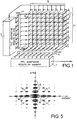
- Figure 1 shows a planar array antenna gathering a set of radiating elements 1 uniformly distributed over m columns and n lines according to a mesh of approximately ⁇ / 2 ( ⁇ being the wavelength antenna usage) to meet the sampling criteria of surface ensuring the absence of network lobes in the case of a wide angle electronic scan.
- Each radiating element 1 is individually equipped with a phase shift module controlled 2 supplemented by a controlled attenuator module 3.
- the ordered modules 2, 3 are ordered, on the first order, by an antenna pointing circuit (not shown) which directs, both on transmission and on reception, the antenna wave plane in the desired direction in deposit and site, playing mainly on the phases and incidentally on the signal levels of the different radiating elements to shape the shape of the lobe (s).
- the outputs of the ordered modules 2, 3 are subject to two groupings: a first grouping in n horizontal alignments of m elements parallel to the bearing axis and a second grouping in m vertical alignments of n elements parallel to the site axis. These two groupings are obtained by means of two crossed and superimposed sets of distributors.
- the latter share the reception signal available at the output of a controlled module 2, 3 into a first and a second component available in parallel and combine on the one hand, the first component with the first components from the other controlled modules 2, 3 belonging to the same horizontal alignment to form a reception signal ⁇ gi, and on the other hand, the second component with the second components from the other controlled modules belonging to the same vertical alignment to form a reception signal ⁇ si .
- reception signals ⁇ gi of all the horizontal alignments of radiating elements 1 are applied by means of a bank 4 of analog-digital converters to a first circuit 5 of adaptive reduced beam formation by the calculation elaborating correction commands to the ordered modules 2, 3 being added, in the second order, to the commands developed by the pointing circuit.
- the reception signals ⁇ if from all the vertical alignments of radiating elements 1 are applied by means of another bank 6 of analog-digital converters to a second circuit 7 of adaptive formation reduced in beam by the calculation forming a reception channel of the global antenna.
- the first circuit 5 of reduced adaptive beam formation by calculation analyzes the disturbances in elevation of the wave plane received by the network antenna and deduces the corrections to be made to the commands designed by the pointing circuit for the various modules controlled 2, 3 to attenuate the disturbances detected. It allows to create, in the radiation pattern on reception of the antenna network, crevices in site in the form of horizontal valleys for eliminate disturbing signals shifted in elevation relative to the axis of pointing the antenna.
- the second circuit 7 of adaptive training reduced by beam by calculation analyzes the disturbances in plane bearing wave received by the network antenna and deduces the amplitude corrections and phase to be brought to the alignment reception signals radiating elements 1 to reduce disturbances detected before summing these reception signals to generate a global signal of reception of the network antenna. It allows you to create, in the radiation pattern of the receiving network antenna, crevices in deposits in the form of vertical valleys to eliminate disturbing signals offset in bearing with respect to the axis of pointing the network antenna.
- the first and second circuits 5 and 7 of adaptive training reduced beam by calculation will not be detailed here as they emerge from the usual anti-jamming technique by means of a adaptive beam formation by calculation based on the search for level and, second order, phase correction of signals of reception used to minimize the power of the overall reception signal, in accordance with the assumption that the disturbing signals that one seeks to eliminate have a power in general superior to that of the useful signal and come from a direction at minus a little different from the pointing of the network antenna.
- Figures 2, 3 and 4 show, plotted in a trihedron of direct reference whose OX axis is graduated in bearing angle, the OY axis in elevation angle and the OZ axis in signal level, the cross-sections in the plane XOZ and YOZ of the antenna radiation pattern surfaces network obtained for reception operation, respectively, in the case of the implementation of the only first training circuit 5 adaptive reduced beam in elevation, in the case of implementation of the only second circuit 7 of reduced adaptive beam formation in deposit and in the case of the combined implementation of the first and second circuits 5 and 7 of adaptive reduced beam formation in site and deposit.
- Figure 2 represents the radiation diagram obtained for the network antenna operating in reception with the only first circuit 5 of reduced adaptive beam formation by operating calculation on the reception signals of the horizontal alignments of elements radiant 1 fitted with controlled modules 2, 3. It has a lobe main end oriented in the direction of pointing determined by the first order settings of the modules ordered 2, 3 imposed by the pointing circuit, and side lobes.
- the side lobes have lower amplitudes in the XOZ field plan because the formation reduced beam is based on solid horizontal alignments and amplitudes more marked in the YOZ site map but with zeros dividers in the form of valleys parallel to the deposit axis and adjustable site positions by the adaptive action of the reduced formation beam.
- FIG. 3 represents the radiation diagram obtained for the network antenna operating in reception with the only second circuit 7 of adaptive reduced beam formation by calculation delivering the overall reception signal from the network antenna. It has a main lobe end oriented in the pointing direction determined by the first order settings of the modules ordered 2, 3 imposed by the pointing circuit, and side lobes.
- the side lobes have lower amplitudes in the YOZ site plan because the reduced formation of beam is based on solid vertical alignments and amplitudes more marked in the XOZ deposit plan but with zeros dividers in the form of valleys parallel to the site axis and adjustable bearing positions by the adaptive action of the formation reduced beam.
- FIG. 4 represents the radiation diagram obtained for the network antenna operating in reception following the combination of the actions of the two adaptive training circuits 5 and 7 reduced beam.
- the adaptive actions of the two training successive beams, one in the site plane and the other in the plane deposit result in the creation of crevices in the form of valleys some parallel to the deposit axis, others parallel to the site axis, each crevice consuming only one degree of freedom in a single reduced adaptive beamforming.
- the zeros or crevices created by both adaptive reduced beam training treatments by calculation be in the shape of a valley and not of a well is an advantage if we consider the shape of the ambiguity diagram of an antenna to separate illumination on site and site.
- the secondary lobes are formed, by amplitudes decreasing, of side lobes 10 which are distributed around the lobe main, in alignments along the main site axes and deposit, and lateral side lobes 11 which are distributed in chessboard. Since, with the exception of the main lobe, it is on the lobes side that the most disturbance is felt, Adaptive valley-shaped zeros are particularly suitable for alignment arrangements of the secondary lobes.
- a network antenna implementing, for anti-jamming, successively, two adaptive formations reduced beam by calculation, a first hybrid acting upstream on the settings of the modules controlled by the radiating elements of the antenna and operating from a grouping of radiating elements of the antenna by horizontal alignments, and a second purely digital downstream delivering a global antenna reception signal network and operating from a grouping of radiating elements of the antenna by vertical alignments.
- Adaptive corrections applied to modules ordered can only correspond to one solution for one single lobe formed.
- Those applied in digital can be parallel solutions applied to multiple lobes. It follows, for a solution with multiple lobes in parallel, that these cannot be formed only in the plane where the adaptive beamforming is fully digital.
- the network antenna which has just been described is an antenna network full. It could obviously be incomplete or rarefied In this case, in the absence of disturbances, the two formations adaptive beam reduced by calculation made successively leave any network or diffuse lobes due to the lacunarity or scarcity while in the presence of disturbances, adaptive cracks or zeros created are those of an adaptive formation of beam by calculation in the environment of diffuse or lateral of the antenna as it is.
- a typical application of the anti-jamming network antenna in reception which has just been described is that of a network antenna for a 3D radar (site, deposit, distance).
- the network antenna For a main lobe of the diagram radiation with an opening of 2 ° in elevation and 1.5 ° in bearing the network antenna must have approximately 80 columns of 54 radiating elements, a total of around 4,320 elements radiant.
- the anti-jamming processing in reception is ensured successively, by the first training adaptive reduced hybrid beam acting on the controls of radiating elements controlled modules, which has 54 moments in site, and by the second reduced adaptive beam formation purely digital delivering a global reception signal, which has 80 moments in deposit.
- the number of degrees of freedom being (54-1) + (80-1) reception anti-jamming is in principle capable confront 132 jammers which ensures a large margin operational.
Abstract
Description
La présente invention concerne une antenne pour ondes radioélectriques ou ultrasonores, de type réseau, antibrouillée en réception, avec des éléments rayonnants ou des groupes d'éléments rayonnants équipés individuellement de modules actifs ou passifs commandés en amplitude et en phase permettant un pointage, à l'émission comme à la réception, par formation analogique de faisceau et avec des moyens de formation adaptative de faisceau par le calcul réalisant l'antibrouillage de réception.The present invention relates to a wave antenna radio or ultrasonic, network type, anti-jamming in reception, with radiant elements or groups of elements radiators individually equipped with active or passive modules amplitude and phase controlled allowing pointing, at emission as at reception, by analog beam formation and with means of adaptive beam formation by calculation performing reception jamming.
Dans la suite, les modules actifs ou passifs commandés en amplitude et en phase seront simplement appelés modules commandés dans un unique but de simplification.In the following, the active or passive modules ordered in amplitude and in phase will be simply called ordered modules for the sole purpose of simplification.
Une antenne réseau est constituée d'un assemblage d'éléments rayonnants répartis en un réseau, la plupart du temps surfacique, selon un maillage d'environ la moitié λ/2 de la longueur d'onde du rayonnement émis ou reçu pour éviter l'apparition de lobes de réseau perturbant la directivité de l'antenne.A network antenna consists of an assembly of elements radiant distributed in a network, mostly surface, according to a mesh of about half λ / 2 of the wavelength of the radiation emitted or received to avoid the appearance of network lobes disrupting the directivity of the antenna.
Le dimensionnement d'une antenne est fonction de l'amplitude du signal à recevoir c'est-à-dire du rapport signal à bruit désiré en réception et de la résolution angulaire souhaitée.The dimensioning of an antenna depends on the amplitude of the signal to be received, i.e. the desired signal-to-noise ratio in reception and the desired angular resolution.
Dans la plupart des cas, les signaux à recevoir sont caractérisés par une densité surfacique de puissance uniforme au lieu de réception de sorte que la puissance du signal utile reçu croít comme la surface utile de l'antenne.In most cases, the signals to be received are characterized by a uniform power surface density instead of reception so that the strength of the received useful signal increases as the useful surface of the antenna.
La résolution angulaire est, quant à elle, définie dans chaque direction par la dimension linéaire L de l'antenne dans la direction considérée rapportée à la longueur d'onde λ dans la relation λ/L, la résolution angulaire solide étant définie dans le rapport λ2/S ou S est la surface de l'antenne.The angular resolution is, for its part, defined in each direction by the linear dimension L of the antenna in the direction considered relative to the wavelength λ in the relation λ / L, the solid angular resolution being defined in the ratio λ 2 / S or S is the surface of the antenna.
Dans la pratique, l'exigence de finesse de résolution angulaire est plus difficile à satisfaire que celle d'un rapport signal/bruit élevé de sorte que l'on aboutit, si aucun compromis n'est accepté, à des éléments rayonnants en surnombre. Comme l'on cherche, pour des raisons de coût, à limiter le plus possible le nombre d'éléments rayonnants d'une antenne réseau, il est intéressant de lutter contre ce surnombre en laissant des vides dans le maillage des éléments rayonnants à la surface d'une antenne réseau. L'antenne réseau est alors dite lacunaire ou raréfiée selon que le nombre d'éléments rayonnants manquants est inférieur ou supérieur au nombre d'éléments rayonnants présents.In practice, the requirement for fine angular resolution is more difficult to satisfy than that of a high signal-to-noise ratio of so that we end up, if no compromise is accepted, with elements radiant in excess. As we seek, for reasons of cost, to limit as much as possible the number of radiating elements of a network antenna, it is interesting to combat this excess in leaving gaps in the mesh of radiating elements on the surface a network antenna. The network antenna is then called incomplete or rarefied according to whether the number of missing radiating elements is lower or higher than the number of radiating elements present.
Dans une antenne réseau lacunaire ou raréfiée, l'absence de certains éléments rayonnants fait que le maillage à environ λ/2 n'est plus respecté ce qui conduit à l'apparition de lobes de réseau si la disposition des éléments rayonnants manquants est périodique ou de lobes diffus si cette disposition est aléatoire. Il importe de réduire le plus possible ces lobes de réseau et diffus.In a patchy or scarce network antenna, the absence of certain radiating elements means that the mesh at approximately λ / 2 is no longer respected which leads to the appearance of network lobes if the disposition missing radiating elements is periodic or diffuse lobes if this arrangement is random. It is important to minimize these network and diffuse lobes.
Une antenne reseau peut être à pointage mécanique ou électronique. Lorsque le pointage est électronique, il se fait à l'émission par une formation analogique de faisceau alors qu'à la réception, il peut se faire soit par une formation analogique de faisceau, soit par une formation de faisceau par le calcul.A network antenna can be mechanically pointing or electronic. When the score is electronic, it is done at the show by an analog beam formation while at the reception, it can be done either by an analog beam formation, or by a beamforming by calculation.
La formation analogique de faisceau nécessite d'équiper individuellement les éléments rayonnants de l'antenne ou des groupes d'éléments rayonnants avec des modules actifs ou passifs commandés en amplitude et en phase permettant d'orienter le plan des ondes émises ou reçues dans la direction voulue. Elle a l'avantage de fonctionner aussi bien à l'émission qu'à la réception. Eventuellement, une commande d'amplitude ou un réseau de distribution permettent une pondération en amplitude.Analog beam formation requires equipping individually the radiating elements of the antenna or groups radiant elements with active or passive modules controlled by amplitude and phase making it possible to orient the plane of the waves emitted or received in the desired direction. It has the advantage of also working both at transmission and at reception. Optionally, an order amplitude or a distribution network allow weighting in amplitude.
La formation de faisceau par le calcul consiste à numériser les signaux reçus par chacun des éléments rayonnants après qu'ils aient été démodulés de façon cohérente puis à les déphaser individuellement et à en faire une somme pondérée par calculateur pour orienter le plan des ondes reçues dans la direction voulue. Elle a l'avantage de donner une grande souplesse à la formation de faisceau puisqu'il est possible de former simultanément par le calcul plusieurs faisceaux pointant dans des directions différentes. Elle permet en outre, lorsqu'elle est adaptative, de faire de l'antibrouillage par ajustement de la position des zéros dans le diagramme rayonnement. Cependant, elle a le désavantage de ne pas être utilisable à l'émission, de nécessiter un équipement coûteux pour la numérisation des signaux des éléments rayonnants et de réclamer une quantité de calculs très importante. Beam formation by calculation consists in digitizing the signals received by each of the radiating elements after they have been demodulated in a coherent way and then to phase them individually and to make it a weighted sum by calculator to orient the plane of waves received in the desired direction. It has the advantage of giving a great flexibility in beam formation since it is possible to simultaneously form by calculation several beams pointing in different directions. It also allows, when it is adaptive, to anti-jamming by adjusting the position of the zeros in the radiation diagram. However, it has the disadvantage of not being usable at transmission, to require expensive equipment for the scanning the signals from the radiant elements and claiming a very large amount of calculations.
Pour limiter le coût d'une formation de faisceau par le calcul on a pensé diviser le réseau de l'antenne en sous-réseaux et réaliser la formation de faisceau par le calcul sous forme réduite non pas sur les signaux individuels des éléments rayonnants mais sur les signaux délivrés individuellement par des regroupements en sous-réseaux des éléments rayonnants. Le maillage de l'antenne à environ λ/2 n'est plus respecté ce qui conduit à l'apparition de lobes de réseau et/ou de lobes diffus de sorte que la formation réduite de faisceau conduit à des performances médiocres de l'antenne sur un large champ angulaire. Elle reste cependant intéressante, sous sa forme adaptative, pour de l'antibrouillage angulaire ponctuel car celui-ci ne nécessite pas, pour être efficace, que la formation de faisceau porte sur un grand nombre de signaux de réception.To limit the cost of beam formation by calculation we thought of dividing the antenna network into sub-networks and carrying out the beamforming by calculation in reduced form not on individual signals of the radiating elements but on the signals delivered individually by grouping elements into subnets radiant. The antenna mesh at about λ / 2 is no longer respected this which leads to the appearance of network lobes and / or diffuse lobes of so that reduced beam formation leads to performance mediocre antenna over a wide angular field. She stays however interesting, in its adaptive form, for anti-jamming angular point because this does not require, to be effective, that the beamforming involves a large number of signals from reception.
Compte tenu de ces considérations et du fait qu'une antenne réseau est souvent employée à la fois à l'émission et à la réception, il est usuel d'équiper les éléments rayonnants d'une antenne réseau individuellement ou par groupe, de modules commandés permettant un pointage par formation de faisceau analogique et de regrouper en réception les éléments rayonnants de l'antenne en sous-réseaux pour effectuer un antibrouillage par une formation adaptative réduite de faisceau par le calcul, le regroupement en réception des éléments rayonnants s'effectuant en sous-réseaux surfaciques et la formation adaptative réduite de faisceau par le calcul s'effectuant dans les deux directions de pointage, gisement et site.Given these considerations and the fact that an antenna network is often used for both transmitting and receiving it is usual to equip the radiating elements with a network antenna individually or in groups, of modules ordered allowing a pointing by analog beam formation and regrouping in reception of the radiating elements of the antenna in sub-networks for perform anti-jamming by a reduced adaptive formation of beam by calculation, grouping in reception of the elements radiant in surface arrays and training adaptive reduced beam by the calculation being carried out in the two pointing directions, deposit and site.
La formation adaptative réduite de faisceau par le calcul engendre un diagramme de rayonnement dont le lobe principal conserve la direction de pointage produite par les modules commandés mais dont les zéros sont déplacés en direction des brouilleurs, cela en jouant principalement sur les amplitudes relatives et éventuellement, au second ordre, sur les déphasages relatifs imposés aux signaux de réception des sous-réseaux. L'énergie totale étant conservée, ce diagramme de rayonnement garde l'inconvénient de présenter des lobes de réseau à des positions angulaires discrètes ou des lobes diffus selon que l'organisation des sous-réseaux surfaciques dans l'antenne est périodique ou aléatoire car les sous-réseaux ont nécessairement des centres de phase espacés d'une distance supérieure ou égale à λ traduisant un sous-échantillonnage de la surface de l'antenne.Reduced adaptive beamforming by calculation generates a radiation diagram of which the main lobe retains the pointing direction produced by the modules ordered but whose the zeros are moved towards the jammers, this by playing mainly on the relative amplitudes and possibly on the second order, on the relative phase shifts imposed on the reception signals of the subnets. The total energy being conserved, this diagram of radiation keeps the disadvantage of presenting network lobes to discrete angular positions or diffuse lobes depending on whether the organization surface sub-networks in the antenna is periodic or random because subnets necessarily have spaced phase centers a distance greater than or equal to λ reflecting a subsampling of the antenna surface.
Pour limiter cet inconvénient, il a été proposé, dans la demande de brevet français FR-2.712.121 déposée par la demanderesse, d'effectuer sur une antenne réseau, un pointage par formation analogique de faisceau complété par un antibrouillage' en réception au moyen de deux formations réduites de faisceau par le calcul appliquées aux signaux de réception des éléments rayonnants équipés de modules commandés, regroupés en deux ensembles de sous-réseaux linéaires parallèles orientés selon deux directions différentes et au moyen d'une combinaison non linéaire des deux signaux de réception résultant des deux formations réduites de faisceau par le calcul. Cette manière de faire entraíne une réduction des perturbations entrant par les lobes secondaires et particulièrement par les lobes de réseau dans le cas d'une antenne lacunaire. Cependant, le traitement non linéaire de regroupement des signaux de réception résultant des deux formations réduites de faisceau par le calcul peut engendrer des produits d'intermodulation si plusieurs signaux sont présents dans la même case distance d'une même cellule angulaire : une cible et un fouillis par exemple. Cet inconvénient peut être contourné par un filtrage Doppler en amont du regroupement des deux signaux de réception résultant des formations réduites de faisceau par le calcul mais cela signifie qu'il faut doubler les équipements de filtrage Doppler.To limit this drawback, it has been proposed in the application French patent FR-2,712,121 filed by the applicant, perform a pointing by analog training on a network antenna beam supplemented by anti-jamming 'on reception by means of two computationally reduced beamforms applied to signals receiving radiating elements fitted with controlled modules, grouped into two sets of oriented parallel linear subnetworks in two different directions and by means of a combination not linear of the two reception signals resulting from the two formations beam reduced by calculation. This way of doing things reduction of disturbances entering through the side lobes and particularly by the network lobes in the case of an antenna incomplete. However, the non-linear processing of grouping of reception signals resulting from the two reduced beam formations by calculation can generate intermodulation products if several signals are present in the same distance cell of the same cell angular: a target and a clutter for example. This drawback can be bypassed by Doppler filtering upstream of the grouping of the two reception signals resulting from reduced beam formations by the calculation but this means that the filtering equipment must be doubled Doppler.
La présente invention a pour but une antenne réseau à pointage par formation de faisceau analogique et à antibrouillage en réception au moyen de formations réduites adaptatives de faisceau par le calcul entraínant un bas niveau de lobes secondaires ou de lobes diffus, que cette antenne réseau soit pleine, lacunaire ou raréfiée.The object of the present invention is a pointing network antenna by analog beam formation and anti-jamming in reception at means of adaptive reduced beam formations by calculation resulting in a low level of side lobes or diffuse lobes, that this network antenna is full, incomplete or rarefied.
Elle a pour objet une antenne réseau antibrouillée en réception, pourvue d'éléments rayonnants équipés individuellement ou par groupes de modules actifs ou passifs commandés en amplitude et en phase permettant un pointage à l'émission comme à la réception, par formation analogique de faisceau, et d'un circuit d'antibrouillage en réception comportant :
- des premiers moyens de formation adaptative réduite de faisceau par le calcul opérant sur des signaux de réception issus des modules commandés, et regroupés d'une première manière en sous-réseaux linéaires parallèles à une première direction, déterminant des corrections à imposer aux signaux de réception provenant des différents sous-réseaux linéaires pris en compte pour éliminer des brouilleurs et appliquant ces corrections aux modules commandés, et
- des deuxièmes moyens de formation adaptative réduite de faisceau par le calcul opérant sur des signaux de réception issus des modules commandés, et regroupés d'une deuxième manière en sous-réseaux linéaires parallèles à une deuxième direction, déterminant des corrections à imposer aux signaux de réception provenant des différents sous-réseaux pris en compte pour éliminer des brouilleurs, imposant ces corrections aux signaux de réception provenant des différents sous-réseaux pris en compte avant de les sommer pour former une voie de réception pour l'antenne globale.
- first means of adaptive reduced beam formation by calculation operating on reception signals from the controlled modules, and grouped in a first way in linear sub-networks parallel to a first direction, determining corrections to be imposed on the reception signals from the different linear sub-networks taken into account to eliminate jammers and applying these corrections to the modules ordered, and
- second means for adaptive reduced beam formation by calculation operating on reception signals from the controlled modules, and grouped in a second manner in linear sub-networks parallel to a second direction, determining corrections to be imposed on the reception signals coming from the different sub-networks taken into account to eliminate interferers, imposing these corrections to the reception signals coming from the different sub-networks taken into account before summing them to form a reception channel for the global antenna.
On réalise ainsi l'antibrouillage en réception d'une antenne réseau à pointage électronique par formation analogique de faisceau au moyen de deux formations adaptatives réduites de faisceau par le calcul successives entraínant pour l'antenne une charge de traitement réduite par rapport à celle d'une formation adaptative complète de faisceau par le calcul partant des signaux de réception délivrés individuellement par les modules commandés raccordés aux éléments rayonnants de l'antenne tout en offrant une réduction comparable des perturbations entrant par les lobes secondaires et lobes de réseau.Anti-jamming is thus carried out upon reception of an antenna electronically-pointing network by analog beam formation at by means of two adaptive beam formations reduced by calculation successive resulting in a reduced processing load for the antenna compared to that of a full adaptive beam formation by the calculation based on the reception signals delivered individually by the controlled modules connected to the radiating elements of the antenna while providing a comparable reduction in disturbance from the side lobes and network lobes.
Avantageusement, les directions des deux ensembles de sous-réseaux linéaires sont orthogonales et orientées l'une selon le plan site et l'autre selon le plan gisement de l'antenne réseau.Advantageously, the directions of the two sets of subnets linear are orthogonal and oriented one according to the site plan and the other according to the network antenna field plan.
D'autres caractéristiques et avantages de l'invention ressortiront de la description ci-après d'un mode de réalisation donné à titre d'exemple. Cette description sera faite en regard du dessin dans lequel :
- une figure 1 représente, de manière schématique, une antenne réseau antibrouillée selon l'invention,
- une figure 2 représente l'effet, sur le diagramme de rayonnement en réception d'une l'antenne réseau, du circuit de formation adaptative réduite de faisceau en site utilisé dans l'antenne réseau antibrouillée de la figure 1,
- une figure 3 représente l'effet, sur le diagramme de rayonnement en réception d'une antenne réseau, du circuit de formation adaptative réduite de faisceau en gisement utilisé dans l'antenne réseau antibrouillée de la figure 1,
- une figure 4 représente les effets combinés, sur le diagramme de rayonnement en réception d'une antenne réseau, des deux circuits de formation adaptative réduite de faisceau en site et gisement utilisés dans l'antenne réseau antibrouillée de la figure 1, et
- une figure 5 est un diagramme illustrant le positionnement, dans le plan site-gisement, des lobes latéraux du diagramme de rayonnement d'une antenne réseau par rapport au lobe principal.
- FIG. 1 schematically represents an anti-jammed array antenna according to the invention,
- FIG. 2 represents the effect, on the radiation diagram on reception of a network antenna, of the reduced adaptive beam formation circuit in elevation used in the scrambled network antenna of FIG. 1,
- FIG. 3 represents the effect, on the radiation diagram on reception of a network antenna, of the adaptive reduced beam formation in field circuit used in the scrambled network antenna of FIG. 1,
- FIG. 4 represents the combined effects, on the radiation pattern on reception of a network antenna, of the two circuits of reduced adaptive formation of beam in elevation and field used in the scrambled network antenna of FIG. 1, and
- FIG. 5 is a diagram illustrating the positioning, in the site-field plane, of the lateral lobes of the radiation diagram of a network antenna with respect to the main lobe.
La figure 1 montre une antenne réseau plan rassemblant un ensemble d'éléments rayonnants 1 uniformément répartis sur m colonnes et n lignes selon un maillage d'environ λ/2 (λ étant la longueur d'onde d'utilisation de l'antenne) pour répondre au critère d'échantillonnage de surface garantissant l'absence de lobes de réseau dans le cas d'un balayage électronique sur un grand angle. Chaque élément rayonnant 1 est équipé individuellement d'un module déphaseur commandé 2 complété par un module atténuateur commandés 3.Figure 1 shows a planar array antenna gathering a set of radiating elements 1 uniformly distributed over m columns and n lines according to a mesh of approximately λ / 2 (λ being the wavelength antenna usage) to meet the sampling criteria of surface ensuring the absence of network lobes in the case of a wide angle electronic scan. Each radiating element 1 is individually equipped with a phase shift module controlled 2 supplemented by a controlled attenuator module 3.
Il est possible, dans le soucis de simplifier la configuration de l'antenne, de faire desservir plusieurs éléments rayonnants de l'antenne par un même module commandé 2.It is possible, for the sake of simplifying the configuration of the antenna, to serve several radiating elements of the antenna by the same controlled module 2.
Les modules commandés 2, 3 sont commandés, au premier ordre, par un circuit de pointage d'antenne non représenté qui oriente, aussi bien à l'émission qu'à la réception, le plan d'onde de l'antenne dans la direction voulue en gisement et en site, en jouant essentiellement sur les phases et accessoirement sur les niveaux des signaux des différents éléments rayonnants pour modeler la forme du ou des lobes.The ordered modules 2, 3 are ordered, on the first order, by an antenna pointing circuit (not shown) which directs, both on transmission and on reception, the antenna wave plane in the desired direction in deposit and site, playing mainly on the phases and incidentally on the signal levels of the different radiating elements to shape the shape of the lobe (s).
En réception, les sorties des modules commandés 2, 3 font
l'objet de deux regroupements : un premier regroupement en n
alignements horizontaux de m éléments parallèles à l'axe gisement et un
deuxième regroupement en m alignements verticaux de n éléments
parallèles à l'axe site. Ces deux regroupements sont obtenus au moyen
de deux ensembles croisés et superposés de distributeurs. Ces derniers
partagent le signal de réception disponible en sortie d'un module
commandé 2, 3 en une première et une deuxième composantes
disponibles en parallèle et regroupent d'une part, la première composante
avec les premières composantes issues des autres modules commandés
2, 3 appartenant au même alignement horizontal pour former un signal de
réception Σgi, et d'autre part, la deuxième composante avec les
deuxièmes composantes issues des autres modules commandés
appartenant au même alignement vertical pour former un signal de
réception Σsi. Les signaux de réception Σgi de l'ensemble des alignements
horizontaux d'éléments rayonnants 1 sont appliqués par l'intermédiaire
d'un banc 4 de convertisseurs analogique-numérique à un premier circuit
5 de formation adaptative réduite de faisceau par le calcul élaborant des
commandes de correction à destination des modules commandés 2, 3
s'ajoutant, au deuxième ordre, aux commandes élaborées par le circuit de
pointage. Les signaux de réception Σsi de l'ensemble des alignements
verticaux d'éléments rayonnants 1 sont appliqués par l'intermédiaire d'un
autre banc 6 de convertisseurs analogique-numérique à un deuxième
circuit 7 de formation adaptative réduite de faisceau par le calcul formant
une voie de réception de l'antenne globale.On reception, the outputs of the ordered modules 2, 3 are subject to two groupings: a first grouping in n horizontal alignments of m elements parallel to the bearing axis and a second grouping in m vertical alignments of n elements parallel to the site axis. These two groupings are obtained by means of two crossed and superimposed sets of distributors. The latter share the reception signal available at the output of a controlled module 2, 3 into a first and a second component available in parallel and combine on the one hand, the first component with the first components from the other controlled modules 2, 3 belonging to the same horizontal alignment to form a reception signal Σ gi, and on the other hand, the second component with the second components from the other controlled modules belonging to the same vertical alignment to form a reception signal Σ si . The reception signals Σ gi of all the horizontal alignments of radiating elements 1 are applied by means of a bank 4 of analog-digital converters to a
Le premier circuit 5 de formation adaptative réduite de faisceau
par le calcul analyse les perturbations en site du plan d'onde reçu par
l'antenne réseau et en déduit les corrections à apporter aux commandes
élaborées par le circuit de pointage à destination des divers modules
commandés 2, 3 pour atténuer les perturbations détectées. Il permet de
créer, dans le diagramme de rayonnement en réception de l'antenne
réseau, des crevasses en site ayant la forme de vallées horizontales pour
éliminer les signaux perturbateurs décalés en site par rapport à l'axe de
pointage de l'antenne.The
Le deuxième circuit 7 de formation adaptative réduite de faisceau par le calcul analyse les perturbations en gisement du plan d'onde reçu par l'antenne réseau et en déduit les corrections d'amplitude et de phase à apporter aux signaux de réception des alignements verticaux d'éléments rayonnants 1 pour atténuer les perturbations détectées avant de sommer ces signaux de réception pour engendrer un signal global de réception de l'antenne réseau. Il permet de créer, dans le diagramme de rayonnement de l'antenne réseau en réception, des crevasses en gisement ayant la forme de vallées verticales pour éliminer les signaux perturbateurs décalés en gisement par rapport à l'axe de pointage de l'antenne réseau.The second circuit 7 of adaptive training reduced by beam by calculation analyzes the disturbances in plane bearing wave received by the network antenna and deduces the amplitude corrections and phase to be brought to the alignment reception signals radiating elements 1 to reduce disturbances detected before summing these reception signals to generate a global signal of reception of the network antenna. It allows you to create, in the radiation pattern of the receiving network antenna, crevices in deposits in the form of vertical valleys to eliminate disturbing signals offset in bearing with respect to the axis of pointing the network antenna.
Les premier et deuxième circuits 5 et 7 de formation adaptative
réduite de faisceau par le calcul ne seront pas détaillés ici car ils
ressortent de la technique habituelle d'antibrouillage au moyen d'une
formation adaptative de faisceau par le calcul basée sur la recherche des
corrections des niveaux et, au deuxième ordre, des phases des signaux
de réception mis à contribution permettant de minimiser la puissance du
signal global de réception, conformément à l'hypothèse selon laquelle les
signaux perturbateurs que l'on cherche à éliminer ont une puissance en
général supérieure à celle du signal utile et proviennent d'une direction au
moins un peu différente de celle de pointage de l'antenne réseau.The first and
Les figures 2, 3 et 4 montrent, tracées dans un trièdre de
référence direct dont l'axe OX est gradué en angle de gisement, l'axe OY
en angle de site et l'axe OZ en niveau de signal, les coupes dans les plan
XOZ et YOZ des surfaces de diagramme de rayonnement de l'antenne
réseau obtenues pour un fonctionnement en réception, respectivement,
dans le cas de la mise en oeuvre du seul premier circuit 5 de formation
adaptative réduite de faisceau en site, dans le cas de la mise en oeuvre
du seul deuxième circuit 7 de formation adaptative réduite de faisceau en
gisement et dans le cas de la mise en oeuvre combinée des premier et
deuxième circuits 5 et 7 de formation réduite adaptative de faisceau en
site et gisement.Figures 2, 3 and 4 show, plotted in a trihedron of
direct reference whose OX axis is graduated in bearing angle, the OY axis
in elevation angle and the OZ axis in signal level, the cross-sections in the plane
XOZ and YOZ of the antenna radiation pattern surfaces
network obtained for reception operation, respectively,
in the case of the implementation of the only
La figure 2 représente le diagramme de rayonnement obtenu
pour l'antenne réseau fonctionnant en réception avec le seul premier
circuit 5 de formation adaptative réduite de faisceau par le calcul opérant
sur les signaux de réception des alignements horizontaux d'éléments
rayonnants 1 équipés de modules commandés 2, 3. Il comporte un lobe
principal fin orienté dans la direction de pointage déterminée par les
réglages au premier ordre des modules commandés 2, 3 imposés par le
circuit de pointage, et des lobes secondaires. Les lobes secondaires ont
des amplitudes plus faibles dans le plan gisement XOZ car la formation
réduite de faisceau est à base d'alignements horizontaux pleins et des
amplitudes plus marquées dans le plan site YOZ mais avec des zéros
intercalaires ayant la forme de vallées parallèles à l'axe gisement et des
positions en site ajustables par l'action adaptative de la formation réduite
de faisceau.Figure 2 represents the radiation diagram obtained
for the network antenna operating in reception with the only
La figure 3 représente le diagramme de rayonnement obtenu pour l'antenne réseau fonctionnant en réception avec le seul deuxième circuit 7 de formation réduite adaptative de faisceau par le calcul délivrant le signal global de réception de l'antenne réseau. Il comporte un lobe principal fin orienté dans la direction de pointage déterminée par les réglages au premier ordre des modules commandés 2, 3 imposés par le circuit de pointage, et des lobes secondaires. Les lobes secondaires ont des amplitudes plus faibles dans le plan site YOZ car la formation réduite de faisceau est à base d'alignements verticaux pleins et des amplitudes plus marquées dans le plan gisement XOZ mais avec des zéros intercalaires ayant la forme de vallées parallèles à l'axe site et des positions en gisement ajustables par l'action adaptative de la formation réduite de faisceau.FIG. 3 represents the radiation diagram obtained for the network antenna operating in reception with the only second circuit 7 of adaptive reduced beam formation by calculation delivering the overall reception signal from the network antenna. It has a main lobe end oriented in the pointing direction determined by the first order settings of the modules ordered 2, 3 imposed by the pointing circuit, and side lobes. The side lobes have lower amplitudes in the YOZ site plan because the reduced formation of beam is based on solid vertical alignments and amplitudes more marked in the XOZ deposit plan but with zeros dividers in the form of valleys parallel to the site axis and adjustable bearing positions by the adaptive action of the formation reduced beam.
La figure 4 représente le diagramme de rayonnement obtenu
pour l'antenne réseau fonctionnant en réception à la suite de la
combinaison des actions des deux circuits 5 et 7 de formation adaptative
réduite de faisceau. Les actions adaptatives des deux formations de
faisceau successives, l'une dans le plan site et l'autre dans le plan
gisement se traduisent par la création de crevasses en forme de vallées
les unes parallèles à l'axe gisement, les autres parallèles à l'axe site,
chaque crevasse ne consommant qu'un degré de liberté dans une seule
formation adaptative réduite de faisceau.FIG. 4 represents the radiation diagram obtained
for the network antenna operating in reception following the
combination of the actions of the two
On remarque que l'utilisation successive, pour de l'antibrouillage en réception, de deux formations adaptatives réduites de faisceau par le calcul portant sur deux regroupements en alignements orthogonaux des éléments rayonnants de l'antenne, l'une agissant en amont sur les modules commandés des éléments rayonnants et l'autre fournissant en aval un signal global de réception de l'antenne réseau permet d'aboutir, du point de vue des lobes secondaires, à un résultat proche de celui d'une formation adaptative complète de faisceau par le calcul, tout en ménageant un nombre suffisant de degrés de liberté (m-1) + (n-1) pour l'élimination des brouilleurs et en réclamant des capacités de traitement bien plus faibles `puisque les formations réduites adaptatives de faisceau par le calcul ne portent plus que sur m + n points au lieu de m x n points.It is noted that the successive use, for anti-jamming in reception, of two adaptive formations reduced in beam by the calculation relating to two groupings in orthogonal alignments of the radiating elements of the antenna, one acting upstream on the modules controlled by radiating elements and the other providing downstream a global signal of reception of the array antenna makes it possible, from the point of view of the secondary lobes, to a result close to that of a complete adaptive formation of beam by the calculation, while providing a sufficient number of degrees of freedom (m-1) + (n - 1) for the elimination of jammers and claiming much lower processing capacities `since the adaptive reduced beam formations by calculation only relate to m + n points instead of mxn points.
Le fait que les zéros ou crevasses créés par les deux
traitements de formation adaptative réduite de faisceau par le calcul
soient en forme de vallée et non de puits est un avantage si l'on
considère la forme du diagramme d'ambiguïté d'une antenne à
illumination séparée en site et gisement. En effet, comme représenté à la
figure 5, les lobes secondaires sont constitués, par amplitudes
décroissantes, de lobes latéraux 10 qui se répartissent autour du lobe
principal, dans des alignements selon les axes principaux site et
gisement, et de lobes latéraux de latéraux 11 qui sont répartis en
échiquier. Comme, à l'exception du lobe principal, c'est sur les lobes
latéraux que les perturbations éventuelles sont le plus ressenties, des
zéros adaptatifs en forme de vallée sont particulièrement adaptés à des
dispositions en alignements des lobes secondaires.The fact that the zeros or crevices created by both
adaptive reduced beam training treatments by calculation
be in the shape of a valley and not of a well is an advantage if we
consider the shape of the ambiguity diagram of an antenna to
separate illumination on site and site. Indeed, as shown in the
Figure 5, the secondary lobes are formed, by amplitudes
decreasing, of
La mise en oeuvre des corrections en amplitude et phase élaborées par le premier circuit de formation réduite adaptative de faisceau par le calcul s'effectuant par des actions sur les modules commandés des éléments rayonnants, un certain laps de temps, très court, est nécessaire pour changer les états des modules commandés. Le temps de calcul des corrections ne s'ajoute pas à ce laps de temps mais, contrairement à une formation réduite adaptative de faisceau classique, le traitement ne peut pas s'appliquer à des signaux provisoirement mémorisés, sans interruption du flux de signaux incidents. Il faut donc accepter une neutralisation d'intervalles de temps de réception pour rafraíchir, quand cela s'impose, les réglages des modules commandés. Pour éviter des périodes de neutralisation périodiques et systématiques, on peut utiliser la fonction d'analyse du premier traitement de formation adaptative réduite de faisceau par le calcul pour surveiller les perturbations et leurs évolutions, et n'interrompre la réception que lorsqu'il se révèle nécessaire de modifier, de manière significative, les réglages des modules commandés. Avec la rapidité des moyens de calcul actuellement disponibles et celle de la micro-électronique hyperfréquence des modules d'antennes actives, il est possible de limiter à une case distance l'interruption de la réception pour la mise à jour des corrections. Dans le cas d'une antenne réseau pour radar à impulsions, il est possible de minimiser les incidences de cette contrainte, en situant les rafraíchissements des corrections sur les réglages des modules commandés en début de récurrence.The implementation of amplitude and phase corrections developed by the first adaptive reduced training circuit of beam by calculation performed by actions on modules ordered radiant elements, a certain amount of time, very short, is necessary to change the states of the modules ordered. The correction calculation time is not added to this period of time but, unlike a conventional adaptive reduced beam training, the processing cannot apply to signals temporarily stored without interrupting the flow of incident signals. Must therefore accept a neutralization of reception time intervals for refresh, when necessary, the settings of the modules ordered. To avoid periodic and systematic neutralization periods, we can use the analysis function of the first training treatment adaptive reduced beam by calculation to monitor disturbances and their evolution, and only interrupt reception when it becomes necessary to significantly modify the settings of the modules ordered. With the speed of the means of calculation currently available and that of microwave microelectronics active antenna modules, it is possible to limit to one box distance the interruption of reception for updating corrections. In the case of a network antenna for pulse radar, it is possible minimize the impact of this constraint, by locating the refreshes of corrections on module settings ordered at the start of recurrence.
On remarque qu'il est possible de dupliquer une ou plusieurs fois le deuxième circuit 7 de formation adaptative réduite de faisceau par le calcul de manière à disposer, à partir de la même antenne, de plusieurs voies de réception pointant dans des directions différentes en gisement. Chaque exemplaire du deuxième circuit 7 de formation adaptative réduite de faisceau par le calcul est alors affecté, au premier ordre, d'un jeu particulier de coefficients complexes de pondération adapté à la direction de pointage en gisement recherchée.We note that it is possible to duplicate one or more times the second circuit 7 of adaptive reduced beam formation by the calculation so as to have, from the same antenna, several reception lines pointing in different directions in the field. Each copy of the second circuit 7 of reduced adaptive training beam by calculation is then assigned, in the first order, a clearance particular of complex weighting coefficients adapted to the direction of pointing in deposit sought.
On a décrit une antenne réseau mettant en oeuvre, pour l'antibrouillage, de manière successive, deux formations adaptatives réduites de faisceau par le calcul, une première hybride agissant en amont sur les réglages des modules commandés des éléments rayonnants de l'antenne et opérant à partir d'un regroupement des éléments rayonnants de l'antenne par alignements horizontaux, et une deuxième purement numérique délivrant en aval un signal global de réception de l'antenne réseau et opérant à partir d'un regroupement des éléments rayonnants de l'antenne par alignements verticaux. On pourrait tout aussi bien faire opérer la première formation adaptative réduite de faisceau de nature hybride à partir d'un regroupement des éléments rayonnants de l'antenne par alignements verticaux et la deuxième formation adaptative réduite de faisceau de nature purement numérique à partir d'un regroupement des éléments rayonnants de l'antenne par alignements horizontaux. Il faut cependant remarquer que la première version est préférable en pratique. En effet, les perturbations par brouillage intentionnel ou fortuit ont, très généralement, une stationnarité plus longue en site qu'en gisement. Il est donc préférable de situer sur l'axe de site le premier traitement hybride de formation adaptative réduite de faisceau qui nécessite de très brèves interruptions de la réception pour les modifications des réglages des modules commandés car alors ces interruptions seront encore moins fréquentes.We have described a network antenna implementing, for anti-jamming, successively, two adaptive formations reduced beam by calculation, a first hybrid acting upstream on the settings of the modules controlled by the radiating elements of the antenna and operating from a grouping of radiating elements of the antenna by horizontal alignments, and a second purely digital downstream delivering a global antenna reception signal network and operating from a grouping of radiating elements of the antenna by vertical alignments. We might as well do operate the first reduced adaptive nature beam formation hybrid from a grouping of the radiating elements of the antenna by vertical alignments and the second reduced adaptive formation of beam of purely digital nature from a grouping of radiating elements of the antenna by horizontal alignments. It is necessary however note that the first version is preferable in practice. Indeed, disturbances by intentional or accidental interference have, very generally, a longer stationarity on site than in a deposit. It is therefore preferable to locate on the site axis the first hybrid treatment of reduced adaptive beamforming which requires very brief reception interruptions for changes to the settings of the modules ordered because then these interruptions will be even less frequent.
Les corrections adaptatives appliquées sur les modules commandés ne peuvent correspondre qu'à une seule solution pour un seul lobe formé. Celles appliquées en numérique peuvent être des solutions parallèles appliquées à des lobes multiples. Il en découle, pour une solution à lobes multiples en parallèles, que ceux-ci ne pourront être formés que dans le plan où la formation de faisceau adaptative est entièrement numérique.Adaptive corrections applied to modules ordered can only correspond to one solution for one single lobe formed. Those applied in digital can be parallel solutions applied to multiple lobes. It follows, for a solution with multiple lobes in parallel, that these cannot be formed only in the plane where the adaptive beamforming is fully digital.
L'antenne réseau qui vient d'être décrite est une antenne réseau pleine. Elle pourrait bien évidemment, être lacunaire ou raréfiée Dans ce cas, en l'absence de perturbations, les deux formations adaptatives réduites de faisceau par le calcul faites successivement laissent en l'état les éventuels lobes de réseau ou diffus dus à la lacunarité ou à la raréfaction tandis qu'en présence de perturbations, les crevasses ou zéros adaptatifs créés sont ceux d'une formation adaptative de faisceau par calcul dans l'environnement de diffus ou de latéraux de l'antenne telle qu'elle est.The network antenna which has just been described is an antenna network full. It could obviously be incomplete or rarefied In this case, in the absence of disturbances, the two formations adaptive beam reduced by calculation made successively leave any network or diffuse lobes due to the lacunarity or scarcity while in the presence of disturbances, adaptive cracks or zeros created are those of an adaptive formation of beam by calculation in the environment of diffuse or lateral of the antenna as it is.
Une application typique de l'antenne réseau antibrouillée en réception qui vient d'être décrite est celle d'une antenne réseau pour un radar 3D (site, gisement, distance). Pour un lobe principal du diagramme de rayonnement ayant une ouverture de 2° en site et 1,5° en gisement l'antenne réseau doit comporter approximativement 80 colonnes de 54 éléments rayonnants soit un totale de l'ordre de 4.320 éléments rayonnants. Avec une telle antenne réseau, le traitement d'antibrouillage en réception est assuré successivement, par la première formation adaptative réduite de faisceau hybride agissant sur les commandes des modules commandés des éléments rayonnants, qui a 54 moments en site, et par la deuxième formation adaptative réduite de faisceau purement numérique délivrant un signal global de réception, qui a 80 moments en gisement. Le nombre de degrés de liberté étant de (54-1) + (80-1) l'antibrouillage de réception est en principe capable d'affronter 132 brouilleurs ce qui assure une importante marge opérationnelle. On remarque en outre que l'on fait une grande économie de traitement par rapport à une formation adaptative complète de faisceau par le calcul puisque les deux formations adaptatives réduites de faisceau ne portent que sur 54 et 80 points au lieu de 4.320.A typical application of the anti-jamming network antenna in reception which has just been described is that of a network antenna for a 3D radar (site, deposit, distance). For a main lobe of the diagram radiation with an opening of 2 ° in elevation and 1.5 ° in bearing the network antenna must have approximately 80 columns of 54 radiating elements, a total of around 4,320 elements radiant. With such a network antenna, the anti-jamming processing in reception is ensured successively, by the first training adaptive reduced hybrid beam acting on the controls of radiating elements controlled modules, which has 54 moments in site, and by the second reduced adaptive beam formation purely digital delivering a global reception signal, which has 80 moments in deposit. The number of degrees of freedom being (54-1) + (80-1) reception anti-jamming is in principle capable confront 132 jammers which ensures a large margin operational. We also notice that we save a lot of treatment versus a full adaptive training of beam by calculation since the two reduced adaptive formations of beam only relate to 54 and 80 points instead of 4.320.
Claims (7)
Applications Claiming Priority (2)
| Application Number | Priority Date | Filing Date | Title |
|---|---|---|---|
| FR9708668A FR2766017B1 (en) | 1997-07-08 | 1997-07-08 | ANTI-FOG NETWORK ANTENNA |
| FR9708668 | 1997-07-08 |
Publications (2)
| Publication Number | Publication Date |
|---|---|
| EP0891005A1 true EP0891005A1 (en) | 1999-01-13 |
| EP0891005B1 EP0891005B1 (en) | 2003-04-02 |
Family
ID=9509010
Family Applications (1)
| Application Number | Title | Priority Date | Filing Date |
|---|---|---|---|
| EP98401718A Expired - Lifetime EP0891005B1 (en) | 1997-07-08 | 1998-07-07 | Array antenna with anti-jamming |
Country Status (5)
| Country | Link |
|---|---|
| US (1) | US6124828A (en) |
| EP (1) | EP0891005B1 (en) |
| CA (1) | CA2241300C (en) |
| DE (1) | DE69812783T2 (en) |
| FR (1) | FR2766017B1 (en) |
Families Citing this family (23)
| Publication number | Priority date | Publication date | Assignee | Title |
|---|---|---|---|---|
| AU2002211881A1 (en) * | 2000-10-13 | 2002-04-22 | Science Applications International Corporation | System and method for linear prediction |
| FR2821164B1 (en) * | 2001-02-16 | 2003-05-16 | Thomson Csf | DISTRIBUTED TRANSMISSION AND RECEPTION SYSTEM, PARTICULARLY RADAR WITH SYNTHETIC TRANSMISSION AND BEAM FORMATION BY CALCULATION |
| US6904444B2 (en) | 2001-04-12 | 2005-06-07 | The United States Of America As Represented By The Secretary Of The Navy | Pseudo-median cascaded canceller |
| US7167884B2 (en) * | 2002-04-22 | 2007-01-23 | The United States Of America As Represented By The Secretary Of The Navy | Multistage median cascaded canceller |
| US8082286B1 (en) | 2002-04-22 | 2011-12-20 | Science Applications International Corporation | Method and system for soft-weighting a reiterative adaptive signal processor |
| US7415065B2 (en) * | 2002-10-25 | 2008-08-19 | Science Applications International Corporation | Adaptive filtering in the presence of multipath |
| US20050003864A1 (en) * | 2003-07-03 | 2005-01-06 | Elliot Robert Douglas | Antenna system |
| US7622529B2 (en) * | 2004-03-17 | 2009-11-24 | Dow Global Technologies Inc. | Polymer blends from interpolymers of ethylene/alpha-olefin with improved compatibility |
| US7317427B2 (en) * | 2005-01-25 | 2008-01-08 | Raytheon Company | Adaptive array |
| FR2885736B1 (en) * | 2005-05-16 | 2007-08-03 | Jean Marc Cortambert | LINEAR SUB-ANTENNA CRUCIFORM ANTENNA AND ASSOCIATED TREATMENT FOR AIRBORNE RADAR |
| FR2885737B1 (en) * | 2005-05-16 | 2008-06-06 | Jean Marc Cortambert | SYSTEM OF CRUCIFORM ANTENNAS WITH LINEAR SUB-ANTENNAS AND TREATMENT THEREOF |
| US10499884B2 (en) | 2012-12-06 | 2019-12-10 | White Eagle Sonic Technologies, Inc. | System and method for scanning for a second object within a first object using an adaptive scheduler |
| US10076313B2 (en) | 2012-12-06 | 2018-09-18 | White Eagle Sonic Technologies, Inc. | System and method for automatically adjusting beams to scan an object in a body |
| US9983905B2 (en) | 2012-12-06 | 2018-05-29 | White Eagle Sonic Technologies, Inc. | Apparatus and system for real-time execution of ultrasound system actions |
| US9529080B2 (en) | 2012-12-06 | 2016-12-27 | White Eagle Sonic Technologies, Inc. | System and apparatus having an application programming interface for flexible control of execution ultrasound actions |
| US9530398B2 (en) | 2012-12-06 | 2016-12-27 | White Eagle Sonic Technologies, Inc. | Method for adaptively scheduling ultrasound system actions |
| CN104038458B (en) | 2013-03-05 | 2019-01-25 | 恩智浦美国有限公司 | BASK demodulator and method for demodulating BASK modulated signal |
| US9778367B2 (en) * | 2013-05-30 | 2017-10-03 | Electronics And Telecommunications Research Institute | Anti-jamming apparatus and method for compact array antenna |
| KR102551252B1 (en) | 2015-11-11 | 2023-07-05 | 삼성메디슨 주식회사 | Ultrasonic diagnostic apparatus and operating method for the same |
| DE102018200751A1 (en) * | 2018-01-18 | 2019-07-18 | Robert Bosch Gmbh | Radar apparatus and method for operating a radar apparatus |
| US11796683B2 (en) | 2018-01-21 | 2023-10-24 | Infinidome Ltd. | Phased-array anti-jamming device and method |
| DE102019204840A1 (en) * | 2019-04-04 | 2020-02-13 | Atlas Elektronik Gmbh | Location signal receiver for the detection of an underwater object with distorted directional characteristics |
| US11506773B1 (en) * | 2022-05-23 | 2022-11-22 | Numerica Corporation | Compact, high-efficiency radar assembly |
Citations (5)
| Publication number | Priority date | Publication date | Assignee | Title |
|---|---|---|---|---|
| US4291310A (en) * | 1979-12-31 | 1981-09-22 | International Telephone And Telegraph Corporation | Adaptive two-dimensional null forming receiving antenna system |
| US4596986A (en) * | 1983-08-29 | 1986-06-24 | The United States Of America As Represented By The Secretary Of The Navy | Sidelobe canceller with adaptive antenna subarraying using a weighted Butler matrix |
| EP0474977A2 (en) * | 1990-08-25 | 1992-03-18 | Siemens Plessey Electronic Systems Limited | Improvements in or relating to radar systems |
| US5343211A (en) * | 1991-01-22 | 1994-08-30 | General Electric Co. | Phased array antenna with wide null |
| EP0651461A1 (en) * | 1993-11-02 | 1995-05-03 | Thomson-Csf | Antenna with array of radiating elements |
Family Cites Families (2)
| Publication number | Priority date | Publication date | Assignee | Title |
|---|---|---|---|---|
| FR2640819B1 (en) * | 1988-12-20 | 1991-05-31 | Thomson Csf | SEMI-RIGID CABLE FOR THE TRANSMISSION OF MICROWAVE WAVES |
| FR2651609B1 (en) * | 1989-09-01 | 1992-01-03 | Thomson Csf | POINT CONTROL FOR AN ELECTRONIC SCANNING ANTENNA SYSTEM AND BEAM FORMATION THROUGH THE CALCULATION. |
-
1997
- 1997-07-08 FR FR9708668A patent/FR2766017B1/en not_active Expired - Fee Related
-
1998
- 1998-07-07 EP EP98401718A patent/EP0891005B1/en not_active Expired - Lifetime
- 1998-07-07 US US09/111,282 patent/US6124828A/en not_active Expired - Fee Related
- 1998-07-07 DE DE69812783T patent/DE69812783T2/en not_active Expired - Fee Related
- 1998-07-07 CA CA002241300A patent/CA2241300C/en not_active Expired - Fee Related
Patent Citations (5)
| Publication number | Priority date | Publication date | Assignee | Title |
|---|---|---|---|---|
| US4291310A (en) * | 1979-12-31 | 1981-09-22 | International Telephone And Telegraph Corporation | Adaptive two-dimensional null forming receiving antenna system |
| US4596986A (en) * | 1983-08-29 | 1986-06-24 | The United States Of America As Represented By The Secretary Of The Navy | Sidelobe canceller with adaptive antenna subarraying using a weighted Butler matrix |
| EP0474977A2 (en) * | 1990-08-25 | 1992-03-18 | Siemens Plessey Electronic Systems Limited | Improvements in or relating to radar systems |
| US5343211A (en) * | 1991-01-22 | 1994-08-30 | General Electric Co. | Phased array antenna with wide null |
| EP0651461A1 (en) * | 1993-11-02 | 1995-05-03 | Thomson-Csf | Antenna with array of radiating elements |
Non-Patent Citations (2)
| Title |
|---|
| COMBAUD M: "Traitement d'antenne par sous-resaux", ONZIÈME COLLOQUE SUR LE TRAITEMENT DU SIGNAL ET DES IMAGES, 1 June 1987 (1987-06-01) - 6 June 1987 (1987-06-06), NICE, pages 419 - 422, XP002058656 * |
| FARINA A AND GIUSTO R: "Wide deterministic nulling by means of multiplicative array techniques", CONFERENCE PROCEEDINGS OF THE 11TH EUROPEAN MICROWAVE CONFERENCE, 7 September 1981 (1981-09-07) - 11 September 1981 (1981-09-11), AMSTERDAM, NETHERLANDS, pages 805 - 812, XP002058657 * |
Also Published As
| Publication number | Publication date |
|---|---|
| CA2241300A1 (en) | 1999-01-08 |
| EP0891005B1 (en) | 2003-04-02 |
| FR2766017A1 (en) | 1999-01-15 |
| DE69812783D1 (en) | 2003-05-08 |
| US6124828A (en) | 2000-09-26 |
| DE69812783T2 (en) | 2004-02-12 |
| FR2766017B1 (en) | 1999-09-24 |
| CA2241300C (en) | 2006-06-06 |
Similar Documents
| Publication | Publication Date | Title |
|---|---|---|
| EP0891005B1 (en) | Array antenna with anti-jamming | |
| EP0651461B1 (en) | Antenna with array of radiating elements | |
| EP0097073B1 (en) | Method and device for the reduction of jamming signal power received by the side lobes of a radar antenna | |
| EP0415818B1 (en) | Control of beam direction for antenna system with electronic scanning and beamforming by computation | |
| EP0014650B1 (en) | Microwave adaptive spatial filter and its method of use in lowering or suppressing the sidelobes of the radiation pattern of an antenna | |
| BE1010979A4 (en) | RADAR NETWORK MONITORING AND PHASE SE SE calibrating ITSELF AND SUBSET EMISSION / RECEPTION INTERCHANGEABLE ADJUSTABLE. | |
| EP2296007B1 (en) | Radar with beam agility, in particular for the function of detecting and avoiding obstacles | |
| FR2491686A1 (en) | MULTIMODE RADAR DIRECTIVE ANTENNA WITH DOUBLE POWER SUPPLY | |
| EP0108670A1 (en) | Feeding device for a scanning array antenna | |
| FR2792116A1 (en) | Phased array antenna digital beam forming method, for communications satellite, converts signals into digital samples to form beam components with same phase | |
| EP0964268B1 (en) | Method for increasing the angular coverage of a beam-forming radar, and radar therefor | |
| FR2465233A1 (en) | APPARATUS FOR DETERMINING AN ULTRASONIC RADAR DEPOSITION | |
| EP1533866B1 (en) | Adaptive phased array antenna with digital beam forming | |
| FR3094797A1 (en) | METHOD AND DEVICE FOR RADAR TRANSMISSION RECEPTION BY DYNAMIC CHANGE OF POLARIZATION, ESPECIALLY FOR THE IMPLEMENTATION OF INTERLACED RADAR MODES | |
| EP3945636A1 (en) | Method for modifying a dispersion diagram of an antenna array, and radar implementing such a method | |
| EP1271689A1 (en) | Repointing system for an reflector antenna array | |
| CA2047032A1 (en) | Elevation angle measuring device for a radar equipped with a double curvature type reflector antenna | |
| CA2031719C (en) | Method and device for imposing a radiation pattern at rest to a receiving antenna array using adaptive beam forming by computation | |
| EP4000131B1 (en) | Multi-panel array antenna | |
| FR3091419A1 (en) | Method for integrating a "network" antenna into a medium of different electromagnetic nature and associated antenna | |
| FR3040794A1 (en) | METHOD FOR TRACKING SATELLITE NAVIGATION SIGNALS | |
| Bucker | Adaptive cross‐sensor beam forming with planar arrays | |
| CA1340234C (en) | Enhanced jamming process | |
| EP0703638A1 (en) | Method and device for enlragement of the radiation diagram for an active antenna | |
| FR3125924A1 (en) | NETWORK ANTENNA |
Legal Events
| Date | Code | Title | Description |
|---|---|---|---|
| PUAI | Public reference made under article 153(3) epc to a published international application that has entered the european phase |
Free format text: ORIGINAL CODE: 0009012 |
|
| AK | Designated contracting states |
Kind code of ref document: A1 Designated state(s): DE FR GB IT |
|
| AX | Request for extension of the european patent |
Free format text: AL;LT;LV;MK;RO;SI |
|
| 17P | Request for examination filed |
Effective date: 19990310 |
|
| AKX | Designation fees paid |
Free format text: DE FR GB IT |
|
| RAP1 | Party data changed (applicant data changed or rights of an application transferred) |
Owner name: THALES |
|
| GRAH | Despatch of communication of intention to grant a patent |
Free format text: ORIGINAL CODE: EPIDOS IGRA |
|
| GRAH | Despatch of communication of intention to grant a patent |
Free format text: ORIGINAL CODE: EPIDOS IGRA |
|
| GRAA | (expected) grant |
Free format text: ORIGINAL CODE: 0009210 |
|
| AK | Designated contracting states |
Designated state(s): DE FR GB IT |
|
| REG | Reference to a national code |
Ref country code: GB Ref legal event code: FG4D Free format text: NOT ENGLISH |
|
| REF | Corresponds to: |
Ref document number: 69812783 Country of ref document: DE Date of ref document: 20030508 Kind code of ref document: P |
|
| GBT | Gb: translation of ep patent filed (gb section 77(6)(a)/1977) |
Effective date: 20030728 |
|
| PLBE | No opposition filed within time limit |
Free format text: ORIGINAL CODE: 0009261 |
|
| STAA | Information on the status of an ep patent application or granted ep patent |
Free format text: STATUS: NO OPPOSITION FILED WITHIN TIME LIMIT |
|
| 26N | No opposition filed |
Effective date: 20040105 |
|
| PGFP | Annual fee paid to national office [announced via postgrant information from national office to epo] |
Ref country code: GB Payment date: 20090701 Year of fee payment: 12 Ref country code: DE Payment date: 20090702 Year of fee payment: 12 |
|
| PGFP | Annual fee paid to national office [announced via postgrant information from national office to epo] |
Ref country code: IT Payment date: 20090721 Year of fee payment: 12 |
|
| GBPC | Gb: european patent ceased through non-payment of renewal fee |
Effective date: 20100707 |
|
| PG25 | Lapsed in a contracting state [announced via postgrant information from national office to epo] |
Ref country code: DE Free format text: LAPSE BECAUSE OF NON-PAYMENT OF DUE FEES Effective date: 20110201 |
|
| REG | Reference to a national code |
Ref country code: DE Ref legal event code: R119 Ref document number: 69812783 Country of ref document: DE Effective date: 20110201 |
|
| PG25 | Lapsed in a contracting state [announced via postgrant information from national office to epo] |
Ref country code: IT Free format text: LAPSE BECAUSE OF NON-PAYMENT OF DUE FEES Effective date: 20100707 |
|
| PG25 | Lapsed in a contracting state [announced via postgrant information from national office to epo] |
Ref country code: GB Free format text: LAPSE BECAUSE OF NON-PAYMENT OF DUE FEES Effective date: 20100707 |
|
| PGFP | Annual fee paid to national office [announced via postgrant information from national office to epo] |
Ref country code: FR Payment date: 20120719 Year of fee payment: 15 |
|
| REG | Reference to a national code |
Ref country code: FR Ref legal event code: ST Effective date: 20140331 |
|
| PG25 | Lapsed in a contracting state [announced via postgrant information from national office to epo] |
Ref country code: FR Free format text: LAPSE BECAUSE OF NON-PAYMENT OF DUE FEES Effective date: 20130731 |