EP0891745A2 - Electrically operated medical device - Google Patents
Electrically operated medical device Download PDFInfo
- Publication number
- EP0891745A2 EP0891745A2 EP98109027A EP98109027A EP0891745A2 EP 0891745 A2 EP0891745 A2 EP 0891745A2 EP 98109027 A EP98109027 A EP 98109027A EP 98109027 A EP98109027 A EP 98109027A EP 0891745 A2 EP0891745 A2 EP 0891745A2
- Authority
- EP
- European Patent Office
- Prior art keywords
- transmitting part
- switch
- receiving station
- signals
- supply
- Prior art date
- Legal status (The legal status is an assumption and is not a legal conclusion. Google has not performed a legal analysis and makes no representation as to the accuracy of the status listed.)
- Granted
Links
Images
Classifications
-
- A—HUMAN NECESSITIES
- A61—MEDICAL OR VETERINARY SCIENCE; HYGIENE
- A61B—DIAGNOSIS; SURGERY; IDENTIFICATION
- A61B18/00—Surgical instruments, devices or methods for transferring non-mechanical forms of energy to or from the body
- A61B18/04—Surgical instruments, devices or methods for transferring non-mechanical forms of energy to or from the body by heating
- A61B18/12—Surgical instruments, devices or methods for transferring non-mechanical forms of energy to or from the body by heating by passing a current through the tissue to be heated, e.g. high-frequency current
- A61B18/1206—Generators therefor
-
- A—HUMAN NECESSITIES
- A61—MEDICAL OR VETERINARY SCIENCE; HYGIENE
- A61B—DIAGNOSIS; SURGERY; IDENTIFICATION
- A61B18/00—Surgical instruments, devices or methods for transferring non-mechanical forms of energy to or from the body
- A61B18/04—Surgical instruments, devices or methods for transferring non-mechanical forms of energy to or from the body by heating
- A61B18/12—Surgical instruments, devices or methods for transferring non-mechanical forms of energy to or from the body by heating by passing a current through the tissue to be heated, e.g. high-frequency current
-
- A—HUMAN NECESSITIES
- A61—MEDICAL OR VETERINARY SCIENCE; HYGIENE
- A61B—DIAGNOSIS; SURGERY; IDENTIFICATION
- A61B17/00—Surgical instruments, devices or methods, e.g. tourniquets
- A61B2017/00973—Surgical instruments, devices or methods, e.g. tourniquets pedal-operated
-
- A—HUMAN NECESSITIES
- A61—MEDICAL OR VETERINARY SCIENCE; HYGIENE
- A61B—DIAGNOSIS; SURGERY; IDENTIFICATION
- A61B18/00—Surgical instruments, devices or methods for transferring non-mechanical forms of energy to or from the body
- A61B2018/00636—Sensing and controlling the application of energy
- A61B2018/0066—Sensing and controlling the application of energy without feedback, i.e. open loop control
-
- A—HUMAN NECESSITIES
- A61—MEDICAL OR VETERINARY SCIENCE; HYGIENE
- A61B—DIAGNOSIS; SURGERY; IDENTIFICATION
- A61B18/00—Surgical instruments, devices or methods for transferring non-mechanical forms of energy to or from the body
- A61B18/04—Surgical instruments, devices or methods for transferring non-mechanical forms of energy to or from the body by heating
- A61B18/12—Surgical instruments, devices or methods for transferring non-mechanical forms of energy to or from the body by heating by passing a current through the tissue to be heated, e.g. high-frequency current
- A61B18/1206—Generators therefor
- A61B2018/1293—Generators therefor having means to prevent interference
Definitions
- the invention relates to an electrically operated medical device, as an electrical-surgical device, according to the preamble of the claim 1.
- connection lines are particularly critical here, which is laid along the floor under the operating table are, e.g. Cables to foot switches, through which the surgeon device functions e.g. can control within a high-frequency surgical device. The foot control is often necessary because the surgeon has both hands needed for manipulation with the instruments, at least of which one is connected to the electrical supply and control unit. Since the electrically operated medical devices mostly for reasons of space at a certain distance from the operating table the pipes on the floor should be relatively long so that they can move freely of people standing around the operating table.
- the aim of the invention is an electrically operated medical To design the device of the type mentioned so that the effort for cable routing is minimized, so that especially in critical Area below and around the operating table are largely prevented by cables laid there.
- line connections between the in particular trained as a foot switch and one preferably close the receiving station arranged in the feed and control device is completely dispensed with, so that the related disabilities of those working at the operating table People are completely avoided.
- a particular problem with electrically operated medical devices is that the interference immunity of the transmission can be very high got to. This is particularly difficult to achieve in operating rooms because there numerous potential interference devices, such as high-frequency surgical devices, X-ray machines, NMR tomographs or similar complicated electronic ones Devices may exist against which there is absolute interference immunity have to be.
- the transmission even in the undisturbed state must so be sure that only the function the surgeon uses the foot switch selects, is switched with high security.
- An advantageous further development of the Invention is taken from claim 4. By digitization or encodability the transmitted signals can be interference as well as mutual Completely exclude influences of foot switches operated in the vicinity.
- the embodiment according to claim 8 is particularly advantageous because in this If the receiving station is only in the receiving socket of a conventional one Foot switch must be plugged in to make the required connection between the foot switch on the transmitter with the power supply and control unit to manufacture.
- a separate charging station to provide for the transmission part, the appropriate place and, if necessary, relative can be located far from the receiving station.
- the charging station should have a holder for the transmitter part, so that this at Non-use can be placed there and during the period of non-use the batteries are charged.
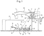
- a side table 33 is arranged on which there is a high-frequency surgical device 12 is located.
- a foot switch 13 is provided by the person working on the operating table 31 Surgeons can be induced by stepping on a pair of switch contacts 13 'to close or open electrically.
- the foot switch 13 is part of a transmitting part 14, the a switching signal conversion stage connected to the switching contact pair 13 ' 19, in which when the switching contact pair 13 'is closed a correspondingly digitized high-frequency signal can be generated, which via a transmission antenna 15 provided in the transmission part 14 a transmission path 32 indicated by dashed lines wirelessly to the receiving antenna 17 can be transmitted to a receiving station 16 at a more suitable Place in the operating room.
- the electrical supply of the switching signal conversion stage 19 in the transmission part 14 takes place via an accumulator 20 which is charged by a charger 26 can be.
- accumulator 20 which is charged by a charger 26 can be.
- Reserve accumulator 22 which automatically when the main accumulator 20 is discharged is connected to the switching signal conversion stage 19, in order to to take over electrical supply.
- a particularly acoustic alarm display 21 within the transmitting part 14 responds when the main accumulator 20 is discharged and the reserve accumulator 22 has taken over the supply.
- Two charging connections lead from the charger 26 to the outside of the transmitting part 14 28, via which the charger 26 is supplied with electrical energy can.
- the receiving station 16 has one connected to the receiving antenna 17 Demodulator 34, which demodulates the received signal and accordingly a switch 35 provided in the receiving station 16 is actuated. In this way, the switch 35 carries out the same switching operations, like the switching contact pair 13 'of the foot switch 13.
- a control line branches 23 to a supply and control device in the form of a high-frequency surgical device 12 and is due to the foot switch switching input 18 a correspondingly designed coupling element connected.
- the Switch 35 of the receiving station 16 causes in the high-frequency surgical device 12 the same switching operations as if a conventional foot switch 13 is connected directly to the switching input 18 via a switching line.
- High-frequency lines extend from the high-frequency surgical device 12 36, 37 to a high-frequency surgical to be operated by the surgeon Electrical instrument 11 or a neutral electrode 38, which with the on the Operating table 31 patients placed in electrically conductive contact becomes.
- the transmission signals 32 still disturbed on the transmission path allowed to be recognized with certainty.
- the charging connections 28 of the transmitting part 14 come automatically in electrically conductive contact with mating connections 29 of the Receiving station 16, the receiving station 16 as long as the power cord 27 is connected to the mains, via the charging connections 28 automatically charging the batteries 20 and 22 in the transmission part 14 ensure.
- the foot switch 13 again automatically ensured that both batteries 20, 22 in full charged state.
- a second foot switch 13 with an identical design Transmitting part 14 are provided. It is also possible that the Foot switch part and the transmitting part 14 via a schematically indicated in Fig. 1 Separation point 39 are connected to each other, so that in the case of a Discharge of the accumulators 20, 22 of the foot switch part at the separation point 39 can be separated from the transmitting part, whereupon a second one is immediately available held transmitter part is plugged in there, whereby the foot switch 13th is fully operational again.
- the transmitting part 14 When not in use, the transmitting part 14 does not have to be at the receiving station 16 can be hung, but can be attached to a wall somewhere Charging station can be attached.
- This version is preferred because because the receiving station 16 can be made very small and therefore e.g. can also be built into the high-frequency surgical device 12.
- the receiving station 16 through a plug adapter with the High-frequency surgical device 12 to connect what may be on the Input socket for the cable of a conventional foot switch could be provided by the receiving station 16 an output signal like a conventional foot switch.
- the plug of a conventional foot switch is obtained remains and only with instead of with a conventional foot switch is connected to the receiving station 16, the switch 35 having. This training is particularly important because at a possible failure of the transmitting part 14 according to the invention is immediately conventional Foot switch can be plugged into the device 12.
Abstract
Description
Die Erfindung betrifft eine elektrisch betriebene medizinische Vorrichtung, wie eine elektrisch-chirurgische Vorrichtung, nach dem Oberbegriff des Patentanspruches 1.The invention relates to an electrically operated medical device, as an electrical-surgical device, according to the preamble of the claim 1.
In Operationssälen werden viele elektrisch betriebene Vorrichtungen verwendet, bei denen zwischen Patient und Vorrichtung elektrische Leitungen oder Schlauchverbindungen vorliegen müssen. Da um den Operationstisch herum wahrend der Operation immer Platzprobleme bestehen, stören derartige Leitungen und Verbindungen erheblich. Besonders kritisch sind hierbei Verbindungsleitungen, die am Boden entlang unter dem Operationstisch verlegt sind, wie z.B. Zuleitungen zu Fußschaltern, über die der Chirurg Gerätefunktionen z.B. innerhalb eines Hochfrequenz-Chirurgiegerätes ansteuern kann. Die Fußbedienung ist deswegen oft notwendig, da der Chirurg beide Hände für das Manipulieren mit den Instrumenten benötigt, von denen mindestens eines an das elektrische Speise- und Steuergerät angeschlossen ist. Da die elektrisch betriebenen medizinischen Vorrichtungen aus Platzgründen meist in einer gewissen Entfernung vom Operationstisch untergebracht sind, müssen die Leitungen am Fußboden relativ lang sein, so daß sie die freie Bewegung der um den Operationstisch herumstehenden Personen behindern.Many electrically operated devices are used in operating theaters, in which electrical lines or between patient and device Hose connections must be available. Because around the operating table Such lines interfere with the operation during the operation and connections significantly. Connection lines are particularly critical here, which is laid along the floor under the operating table are, e.g. Cables to foot switches, through which the surgeon device functions e.g. can control within a high-frequency surgical device. The foot control is often necessary because the surgeon has both hands needed for manipulation with the instruments, at least of which one is connected to the electrical supply and control unit. Since the electrically operated medical devices mostly for reasons of space at a certain distance from the operating table the pipes on the floor should be relatively long so that they can move freely of people standing around the operating table.
Das Ziel der Erfindung besteht darin, eine elektrisch betriebene medizinische Vorrichtung der eingangs genannten Gattung so auszubilden, daß der Aufwand für die Leitungsverlegung minimiert wird, so daß insbesondere im kritischen Bereich unterhalb des Operationstisches und um diesen herum Störungen durch dort verlegte Leitungen weitgehend unterbunden sind. The aim of the invention is an electrically operated medical To design the device of the type mentioned so that the effort for cable routing is minimized, so that especially in critical Area below and around the operating table are largely prevented by cables laid there.
Zur Lösung dieser Aufgabe sind die Merkmale des kennzeichnenden Teils des Anspruches 1 vorgesehen. Bevorzugte Ausführungsformen entnimmt man den Ansprüchen 2 und 3.To solve this problem, the features of the characterizing part of the Claim 1 provided. Preferred embodiments can be found claims 2 and 3.
Erfindungsgemäß wird also auf Leitungsverbindungen zwischen den insbesondere als Fußschalter ausgebildeten Schalter und einer vorzugsweise nahe dem Speise- und Steuergerät angeordneten Empfangsstation völlig verzichtet, so daß die diesbezüglichen Behinderungen der am Operationstisch arbeitenden Personen völlig vermieden sind.According to the invention, line connections between the in particular trained as a foot switch and one preferably close the receiving station arranged in the feed and control device is completely dispensed with, so that the related disabilities of those working at the operating table People are completely avoided.
Ein besonderes Problem bei elektrisch betriebenen medizinischen Vorrichtungen besteht darin, daß die Störsicherheit der Übertragung sehr hoch sein muß. Dies ist in Operationssälen besonders schwierig zu realisieren, da dort zahlreiche potentielle Störvorrichtungen, wie Hochfrequenz-Chirurgiegeräte, Röntgengeräte, NMR-Tomographen oder ähnliche komplizierte elektronische Geräte vorhanden sein können, gegen die eine absolute Störsicherheit gegeben sein muß. Auch die Übertragung selbst im nichtgestörten Zustand muß so sicher sein, daß nur die Funktion, die der Chirurg über den Fußschalter anwählt, mit hoher Sicherheit geschaltet wird. Ein weiteres Problem ergibt sich, wenn möglicherweise in zwei benachbarten Operationssälen Fußschalter der erfindungsgemäßen Art verwendet werden, deren gegenseitige Störung ausgeschlossen sein muß. Eine diesbezüglich vorteilhafte Weiterbildung der Erfindung entnimmt man Anspruch 4. Durch die Digitalisierung bzw. Kodierbarkeit der übertragenen Signale lassen sich Störeinflüsse ebenso wie gegenseitige Beeinflussungen benachbart betriebener Fußschalter vollständig ausschließen. Besonders vorteilhaft ist es, wenn der Sendeteil direkt in den Fußschalter eingebaut ist. Aufgrund moderner elektronischer Bauelemente kann so ein Fußschalter geschaffen werden, der sich äußerlich von einem Fußschalter mit Leitungsübertragung praktisch nicht unterscheidet, jedoch eine drahtlose Übertragung der Schaltsignale zur Empfangsstation ermöglicht. Weiter wird durch diese Merkmale eine völlige Unabhängigkeit des erfindungsgemäß verwendeten Schalters von irgendwelchen äußeren Energiequellen gewährleistet. Weiter werden die Probleme mit einer bevorstehenden Entleerung der Batterien oder Akkumulatoren gut beherrscht.A particular problem with electrically operated medical devices is that the interference immunity of the transmission can be very high got to. This is particularly difficult to achieve in operating rooms because there numerous potential interference devices, such as high-frequency surgical devices, X-ray machines, NMR tomographs or similar complicated electronic ones Devices may exist against which there is absolute interference immunity have to be. The transmission even in the undisturbed state must so be sure that only the function the surgeon uses the foot switch selects, is switched with high security. Another problem arises if, if possible, foot switches in two adjacent operating rooms of the type according to the invention are used, their mutual interference must be excluded. An advantageous further development of the Invention is taken from claim 4. By digitization or encodability the transmitted signals can be interference as well as mutual Completely exclude influences of foot switches operated in the vicinity. It is particularly advantageous if the transmitting part directly into the foot switch is installed. Due to modern electronic components Such a foot switch can be created that differs externally from a foot switch practically no difference with line transmission, but one enables wireless transmission of the switching signals to the receiving station. Furthermore, these features make the invention completely independent switch used from any external energy sources guaranteed. The problems continue with an upcoming one Draining the batteries or accumulators well mastered.
Da medizinische Speise- und Steuergeräte, wie z.B. Elektrochirurgiegeräte, einen normalen Steckeingang für einen Schalter, insbesondere Fußschalter aufweisen, ist es zweckmäßig, wenn erfindungsgemäß nach Anspruch 5 vorgegangen wird und die von der Empfangsstation zum Speise- und Steuergerät führende Leitung einen Steckkontakt bzw. Steckbuchse aufweist, die der einer von einem herkömmlichen Fußschalter kommenden Leitung entspricht. Die Empfangsstation kann dann genauso wie ein herkömmlicher Fußschalter mit dem Schalteingang des Speise- und Steuergerätes verbunden werden. Alternativ könnte jedoch die Empfangsstation auch in das Speise- und Steuergerät eingebaut werden. Nachdem zwischen dem Sendeteil und der Empfangsstation keine körperliche Verbindung besteht, ist diese Ausführungsform ebenfalls vorteilhaft, damit auf jeden Fall während des Nichtgebrauchs Sendeteil und Empfangsstation eine körperliche Einheit bilden. Die Merkmale dieser Ausführungsbeispiele dienen auch zur Wiederaufladung von in dem Sendeteil vorgesehenen Akkumulatoren und zum Zwecke der Stromversorgung des Ladegerätes.Since medical supply and control devices, e.g. Electrosurgery equipment, a normal plug input for a switch, especially a foot switch have, it is expedient if the procedure according to the invention is as claimed in claim 5 and from the receiving station to the power supply and control unit leading line has a plug contact or socket, which one line coming from a conventional foot switch. The receiving station can then just like a conventional foot switch be connected to the switching input of the supply and control unit. Alternatively, however, the receiving station could also be in the feed and control device to be built in. After between the transmitting part and the receiving station this embodiment is not a physical connection also advantageous, so that in any case the transmitter part when not in use and the receiving station form a physical unit. The characteristics these embodiments also serve to recharge in the Transmitting part provided batteries and for the purpose of power supply the charger.
Eine weitgehend automatische Aufladung der Akkumulatoren in dem Sendeteil wird durch die Maßnahmen nach Anspruch 6 gewährleistet.A largely automatic charging of the batteries in the transmitter part is guaranteed by the measures according to claim 6.
Um auch durch äußere Einflüsse gestörte Übertragungssignale sicher erkennen zu können, ist die Ausführungsform nach Anspruch 7 zweckmäßig.In order to reliably detect transmission signals disturbed by external influences to be able to, the embodiment according to claim 7 is appropriate.
Besonders vorteilhaft ist die Ausführungsform nach Anspruch 8, weil in diesem Fall die Empfangsstation lediglich in die Empfangsbuchse eines konventionellen Fußschalters eingesteckt werden muß, um die erforderliche Verbindung zwischen dem Fußschalter am Sendeteil mit dem Speise- und Steuergerät herzustellen. The embodiment according to claim 8 is particularly advantageous because in this If the receiving station is only in the receiving socket of a conventional one Foot switch must be plugged in to make the required connection between the foot switch on the transmitter with the power supply and control unit to manufacture.
Nachdem die erfindungsgemäße Empfangsstation sehr klein dimensioniert sein kann, ist es zweckmäßig, nach Anspruch 9 eine gesonderte Ladestation für den Sendeteil vorzusehen, die an geeigneter Stelle und gegebenenfalls relativ weit entfernt von der Empfangsstation angeordnet werden kann. Die Ladestation soll eine Halterung für den Sendeteil aufweisen, so daß dieser bei Nichtgebrauch dort angebracht werden kann und während der Zeit des Nichtgebrauchs eine Aufladung der Akkumulatoren erfolgt.After the receiving station according to the invention is dimensioned very small may be, it is appropriate, according to claim 9, a separate charging station to provide for the transmission part, the appropriate place and, if necessary, relative can be located far from the receiving station. The charging station should have a holder for the transmitter part, so that this at Non-use can be placed there and during the period of non-use the batteries are charged.
Die Erfindung wird im folgenden beispielsweise anhand der Zeichnung beschrieben; in dieser zeigt:
- Fig. 1
- eine schematische Darstellung eines erfindungsgemäß geschalteten Hochfrequenz-Chirurgiegerätes in Anordnung an einem medizinischen Operationstisch.
- Fig. 1
- is a schematic representation of a high-frequency surgical device switched according to the invention arranged in a medical operating table.
Nach Fig. 1 ist neben einem in einem Operationssaal vorgesehenen Operationstisch
31 ein Beistelltisch 33 angeordnet, auf dem sich ein Hochfrequenz-Chirurgiegerät
12 befindet. Unterhalb des Operationstisches ist auf dem Boden
ein Fußschalter 13 vorgesehen, der vom am Operationstisch 31 arbeitenden
Chirurgen durch Niedertreten veranlaßt werden kann, einen Schaltkontaktpaar
13' elektrisch zu schließen oder zu öffnen.1 is next to an operating table provided in an
Erfindungsgemäß ist der Fußschalter 13 Bestandteil eines Sendeteils 14, die
eine an das Schaltkontaktpaar 13' angeschlossene Schaltsignal-Umwandlungsstufe
19 aufweist, in der beim Schließen des Schaltkontaktpaares 13'
ein entsprechend digitalisiertes Hochfrequenzsignal erzeugt werden kann,
welches über eine in dem Sendeteil 14 vorgesehene Sendeantenne 15 über
einen gestrichelt angedeuteten Übertragungspfad 32 drahtlos zur Empfangsantenne
17 einer Empfangsstation 16 übertragen werden kann, die an geeigneter
Stelle im Operationssaal untergebracht ist. According to the
Die elektrische Speisung der Schaltsignal-Umwandlungsstufe 19 in dem Sendeteil
14 erfolgt über einen Akkumulator 20, der von einem Ladegerät 26 aufgeladen
werden kann. Weiter befindet sich innerhalb des Sendeteils 14 ein
Reserveakkumulator 22, der bei Entladung des Hauptakkumulators 20 automatisch
mit der Schaltsignal-Umwandlungsstufe 19 verbunden wird, um dessen
elektrische Speisung zu übernehmen.The electrical supply of the switching
Eine insbesondere akustische Alarmanzeige 21 innerhalb des Sendeteils 14
spricht an, wenn der Hauptakkumulator 20 entladen ist und der Reserveakkumulator
22 die Speisung übernommen hat.A particularly
Vom Ladegerät 26 führen zur Außenseite des Sendeteils 14 zwei Ladeanschlüsse
28, über die das Ladegerät 26 mit elektrischer Energie versorgt werden
kann.Two charging connections lead from the
Die Empfangsstation 16 weist einen an die Empfangsantenne 17 angeschlossenen
Demodulator 34 auf, der das Empfangssignal demoduliert und dementsprechend
einen in der Empfangsstation 16 vorgesehenen Schalter 35 betätigt.
Der Schalter 35 führt auf diese Weise die gleichen Schaltvorgänge aus,
wie das Schaltkontaktpaar 13' des Fußschalters 13.The receiving station 16 has one connected to the
Von der Empfangsstation 16, die über eine Netzanschlußleitung 27 in nicht
dargestellter Weise mit dem Stromnetz verbunden ist, zweigt eine Steuerleitung
23 zu einem Speise- und Steuergerät in Form eines Hochfrequenz-Chirurgiegerätes
12 ab und ist mit dessen Fußschalter-Schalteingang 18 aufgrund
eines entsprechend gestalteten Kupplungselementes verbunden. Der
Schalter 35 der Empfangsstation 16 bewirkt im Hochfrequenz-Chirurgiegerät
12 die gleichen Schaltvorgänge, als wenn ein herkömmlicher Fußschalter 13
unmittelbar über eine Schaltleitung mit dem Schalteingang 18 verbunden ist.From the receiving station 16, which does not have a
Vom Hochfrequenz-Chirurgiegerät 12 erstrecken sich Hochfrequenzleitungen
36, 37 zu einem vom Chirurgen zu bedienendes hochfrequenz-chirurgisches
Elektroinstrument 11 bzw. einer Neutralelektrode 38, die mit dem auf dem
Operationstisch 31 befindlichen Patienten in elektrisch leitenden Kontakt gebracht
wird.High-frequency lines extend from the high-frequency
In der Empfangsstation 16 befindet sich außerdem eine Signalerkennungsstufe
30, die auf dem Übertragungsweg 32 gestörte Übertragungssignale noch
sicher zu erkennen gestattet.In the receiving station 16 there is also a
An der Empfangsstation 16 befindet sich eine Halterung 24, an der mittels
eines Bügels 25 der Fußschalter 13 während des Nichtgebrauchs aufgehängt
werden kann. Hierbei kommen die Ladeanschlüsse 28 des Sendeteils 14 automatisch
in elektrisch leitenden Kontakt mit Gegenanschlüssen 29 der
Empfangsstation 16, die solange die Empfangsstation 16 über die Netzanschlußleitung
27 mit dem Stromnetz verbunden ist, über die Ladeanschlüsse
28 automatisch eine Aufladung der Akkumulatoren 20 und 22 in dem Sendeteil
14 gewährleisten. Bei erneutem Gebrauch des Fußschalters 13 ist somit
automatisch dafür gesorgt, daß beide Akkumulatoren 20, 22 sich im voll
aufgeladenen Zustand befinden.At the receiving station 16 there is a
Um für den Fall, daß sich beide Akkumulatoren 20, 22 während einer Operation
entladen, den Operationsvorgang nicht unterbrechen zu müssen, kann
erfindungsgemäß ein zweiter Fußschalter 13 mit identisch ausgebildetem
Sendeteil 14 zur Verfügung gestellt werden. Auch ist es möglich, daß der
Fußschalterteil und der Sendeteil 14 über eine in Fig. 1 schematisch angedeutete
Trennstelle 39 miteinander verbunden sind, so daß im Falle einer
Entladung der Akkumulatoren 20, 22 der Fußschalterteil an der Trennstelle
39 vom Sendeteil getrennt werden kann, worauf sofort ein zweiter zur Verfügung
gehaltener Sendeteil dort angesteckt wird, wodurch der Fußschalter 13
erneut voll betriebsbereit ist.To in the event that both
Bei Nichtgebrauch muß der Sendeteil 14 nicht an der Empfangsstation 16
eingehängt werden, sondern kann an eine irgendwo an der Wand befestigte
Ladestation angehängt werden. Diese Ausführung ist deswegen bevorzugt,
weil die Empfangsstation 16 sehr klein dimensioniert werden kann und daher
z.B. auch in das Hochfrequenz-Chirurgiegerät 12 eingebaut sein kann. Es ist
auch denkbar, die Empfangsstation 16 durch einen Steckadapter mit dem
Hochfrequenz-Chirurgiegerät 12 zu verbinden, was gegebenenfalls an der
Eingangsbuchse für das Kabel eines konventionellen Fußschalters vorgenommen
werden könnte, indem die Empfangsstation 16 ein Ausgangssignal
wie ein konventioneller Fußschalter liefert. Von besonderer Bedeutung für die
Erfindung ist es also, daß der Stecker eines konventionellen Fußschalters erhalten
bleibt und lediglich statt mit einem konventionellen Fußschalter mit
der Empfangsstation 16 verbunden ist, die an ihrem Ausgang den Schalter 35
aufweist. Diese Ausbildung ist deswegen von besonderer Bedeutung, weil bei
einem etwaigen Ausfall des erfindungsgemäßen Sendeteils 14 sofort ein konventioneller
Fußschalter an das Gerät 12 angesteckt werden kann. When not in use, the transmitting
- 1111
- ElektroinstrumentElectrical instrument
- 1212th
- Speise- und SteuergerätPower supply and control device
- 1313
- FußschalterFootswitch
- 13'13 '
- SchaltkontaktpaarSwitch contact pair
- 1414
- SendeteilTransmitting part
- 1515
- SendeantenneTransmitting antenna
- 1616
- EmpfangsstationReceiving station
- 1717th
- EmpfangsantenneReceiving antenna
- 1818th
- SchalteingangSwitching input
- 1919th
- Schaltsignal-UmwandlungsstufeSwitching signal conversion stage
- 2020th
- HauptakkumulatorMain accumulator
- 2121
- AlarmanzeigeAlarm indicator
- 2222
- ReserveakkumulatorReserve accumulator
- 2323
- Leitungmanagement
- 2424th
- Halterungbracket
- 2525th
- Bügelhanger
- 2626
- Ladegerätcharger
- 2727
- NetzanschlußleitungPower cord
- 2828
- LadeanschlußCharging port
- 2929
- GegenanschlußCounter connection
- 3030th
- SignalerkennungsstufeSignal detection level
- 3131
- OperationstischOperating table
- 3232
- ÜbertragungspfadTransmission path
- 3333
- BeistelltischSide table
- 3434
- DemodulatorDemodulator
- 3535
- Schalter switch
- 3636
- HochfrequenzleitungRadio frequency line
- 3737
- HochfrequenzleitungRadio frequency line
- 3838
- NeutralelektrodeNeutral electrode
- 3939
- TrennstelleSeparation point
Claims (9)
dadurch gekennzeichnet,
daß der Schalter (13) einem Sendeteil (14) zugeordnet ist, die die Schaltsignale in drahtlos übertragbare Signale umwandelt und über ein Sendeelement (15) zu einem Empfangselement (17) einer Empfangsstation (16) sendet, welche an den Schalteingang (18) des Speise- und Steuergeräts (12) angeschlossen ist und ein dem Schaltsignal entsprechendes Steuersignal an das Speise- und Steuergerät (12) überträgt.Electrically operated medical device, such as electrosurgical device, with an electronic instrument (11) which can be handled by a person and which can be connected to an electrically operated supply and control device (12), such as a high-frequency surgical device, which is connected to one of the Person operated switch (13) is connected, by means of which one or more functions of the electrical instrument (11) in the power supply and control unit (12) can be switched on and off via a switching signal triggered by him,
characterized,
that the switch (13) is assigned to a transmitting part (14), which converts the switching signals into wirelessly transmissible signals and sends via a transmitting element (15) to a receiving element (17) of a receiving station (16), which to the switching input (18) of the Feed and control device (12) is connected and transmits a control signal corresponding to the switching signal to the feed and control device (12).
dadurch gekennzeichnet,
daß die drahtlos übertragenen Signale Infrarot-, Ultraschall- oder Hochfrequenzsignale sind.Device according to claim 1,
characterized,
that the wirelessly transmitted signals are infrared, ultrasonic or radio frequency signals.
dadurch gekennzeichnet,
daß der Schalter (13) ein Fußschalter ist.Device according to claim 1 or 2,
characterized,
that the switch (13) is a foot switch.
dadurch gekennzeichnet,
daß in dem Sendeteil (14) eine Schaltsignalumwandlungsstufe (19) vorgesehen ist, die die vom Schalter (13) erhaltenen Schaltsignale in ein drahtlos übertragbares, digitalisiertes Signal umwandelt und/oder daß die drahtlos übertragenen Signale kodierbar bzw. kodiert sind und/oder daß der Schalter (13) Bestandteil des Sendeteils ist und/oder daß der Sendeteil (14) mittels Batterie oder wiederaufladbarer Akkumulatoren (20) betrieben ist, wobei bevorzugt in dem Sendeteil (14) eine Alarmanzeige (21) eingebaut ist, die rechtzeitig vor Entladung der Batterien oder Akkumulatoren (20) anspricht und ein Alarmsignal abgibt und/oder in dem Sendeteil (14) eine Reservebatterie oder ein Reserveakkumulator (22) vorgesehen ist, der bei weitgehender Entladung der Hauptbatterie bzw. des Hauptakkumulators (20) automatisch die Speisung des Sendeteils (14) übernimmt.Device according to one of the preceding claims,
characterized,
that in the transmitting part (14) a switching signal conversion stage (19) is provided, which converts the switching signals received by the switch (13) into a wirelessly transmitted, digitized signal and / or that the wirelessly transmitted signals are encodable or coded and / or that the Switch (13) is part of the transmitting part and / or that the transmitting part (14) is operated by means of a battery or rechargeable batteries (20), an alarm indicator (21) preferably being installed in the transmitting part (14), which in time before the batteries are discharged or accumulators (20) responds and emits an alarm signal and / or a reserve battery or accumulator (22) is provided in the transmitting part (14), which automatically discharges the transmitting part (14) when the main battery or the main accumulator (20) is largely discharged ) takes over.
dadurch gekennzeichnet,
daß die Empfangsstation (16) mittels einer Verbindung (23) mit dem Speise- und Steuergerät (12) verbunden ist, wobei die Verbindung (23) vorzugsweise an ihrem Ende einen Steckkontakt bzw. eine Steckbuchse aufweist, die der eines herkömmlichen Schalters, insbesondere Fußschalters (13) entspricht, so daß die Verbindung (23) einfach statt des Kabels eines herkömmlichen Schalters an das Speise- und Steuergerät (12) angeschlossen werden kann und/oder daß die Empfangsstation (16) eine Halterung (24) für das Sendeteil (14) während des Nichtgebrauchs aufweist und/oder daß das Sendeteil (14) und/oder die Empfangsstation (16) ein Ladegerät (26) für die Akkumulatoren (20, 22) in dem Sendeteil (14) aufweisen, wobei zweckmäßig die Empfangsstation (16) direkt über eine Netzanschlußleitung (27) oder über das Speise- und Steuergerät (12) an das Stromnetz anschließbar ist.Device according to one of the preceding claims,
characterized,
that the receiving station (16) is connected by means of a connection (23) to the supply and control device (12), the connection (23) preferably having at its end a plug contact or a socket which is that of a conventional switch, in particular a foot switch (13), so that the connection (23) can simply be connected to the supply and control device (12) instead of the cable of a conventional switch and / or that the receiving station (16) has a holder (24) for the transmitting part (14 ) when not in use and / or that the transmitting part (14) and / or the receiving station (16) have a charger (26) for the batteries (20, 22) in the transmitting part (14), the receiving station (16) expediently can be connected directly to the mains via a mains connection line (27) or via the supply and control unit (12).
dadurch gekennzeichnet,
daß bei Halterung des Sendeteils (14) insbesondere an der Empfangsstation (16) der bzw. die Akkumulatoren (20, 22) des Sendeteils (14) automatisch aufgeladen werden, wobei insbesondere bei Halterung des Sendeteils (14) an der Empfangsstation (16) während des Nichtgebrauchs Ladeanschlüsse (28) an dem Sendeteil (14) mit Gegenanschlüssen (29) an der Empfangsstation (16) in elektrischen Kontakt kommen oder bei Halterung des Sendeteils (14) an der Empfangsstation (16) während des Nichtgebrauchs die Empfangsstation (16) zur Aufladung der Akkumulatoren (20, 22) mit einem Ladegerät (26) in dem Sendeteil (14) induktiv gekoppelt ist.Device according to claim 5,
characterized,
that when the transmitting part (14) is held, in particular at the receiving station (16), the accumulator (s) (20, 22) of the transmitting part (14) are automatically charged, in particular when the transmitting part (14) is held at the receiving station (16) during when not in use, charging connections (28) on the transmitting part (14) come into electrical contact with mating connections (29) on the receiving station (16) or, when the transmitting part (14) is held on the receiving station (16), the receiving station (16) is used when not in use Charging of the batteries (20, 22) with a charger (26) in the transmitting part (14) is inductively coupled.
dadurch gekennzeichnet
daß die Ausgangssignale einer Vielzähl verschiedener Sender so kodiert sind, daß sie sich nicht gegenseitig beeinflussen, und daß die Empfangsstation (16) eine entsprechende Signalerkennungsstufe (30) aufweist.Device according to one of the preceding claims,
characterized
that the output signals of a large number of different transmitters are coded so that they do not influence one another, and that the receiving station (16) has a corresponding signal detection stage (30).
dadurch gekennzeichnet,
daß die Empfangsstation (16) mittels eines Steckkontaktes unmittelbar an den Eingang des Speise- und Steuergerätes 12 anschließbar ist, der für den Steckkontakt eines konventionellen Fußschalters vorgesehen ist.Device according to one of claims 5 to 7,
characterized,
that the receiving station (16) can be connected directly to the input of the supply and control device 12 by means of a plug contact, which is provided for the plug contact of a conventional foot switch.
dadurch gekennzeichnet,
daß die Ladestation für den Sendeteil (14) separat von der Empfangsstation (16) an geeigneter Stelle vorgesehen ist und der Sendeteil (14) bei Nichtgebrauch von der Ladestation gehalten wird, um die Aufladung des Akkumulators bzw. der Akkumulatoren (20, 22) vorzunehmen.Device according to one of the preceding claims,
characterized,
that the charging station for the transmitting part (14) is provided separately from the receiving station (16) at a suitable location and the transmitting part (14) is held by the charging station when not in use in order to charge the accumulator (s) (20, 22) .
Applications Claiming Priority (2)
| Application Number | Priority Date | Filing Date | Title |
|---|---|---|---|
| DE19730456A DE19730456A1 (en) | 1997-07-16 | 1997-07-16 | Electrically powered medical device |
| DE19730456 | 1997-07-16 |
Publications (3)
| Publication Number | Publication Date |
|---|---|
| EP0891745A2 true EP0891745A2 (en) | 1999-01-20 |
| EP0891745A3 EP0891745A3 (en) | 1999-05-26 |
| EP0891745B1 EP0891745B1 (en) | 2002-12-11 |
Family
ID=7835874
Family Applications (1)
| Application Number | Title | Priority Date | Filing Date |
|---|---|---|---|
| EP98109027A Expired - Lifetime EP0891745B1 (en) | 1997-07-16 | 1998-05-18 | Electrically operated medical device |
Country Status (3)
| Country | Link |
|---|---|
| US (1) | US6074388A (en) |
| EP (1) | EP0891745B1 (en) |
| DE (2) | DE19730456A1 (en) |
Cited By (3)
| Publication number | Priority date | Publication date | Assignee | Title |
|---|---|---|---|---|
| WO2008031571A1 (en) * | 2006-09-12 | 2008-03-20 | Smiths Medical Deutschland Gmbh | Patient monitoring system |
| WO2008113513A1 (en) * | 2007-03-20 | 2008-09-25 | Kaltenbach & Voigt Gmbh | Arrangement for controlling medicinal devices, in particular of a dental work station |
| EP3692942A1 (en) * | 2019-02-06 | 2020-08-12 | W & H Dentalwerk Bürmoos GmbH | Control module for controlling a volume flow of a gaseous propellant of a dental or medical treatment tool |
Families Citing this family (81)
| Publication number | Priority date | Publication date | Assignee | Title |
|---|---|---|---|---|
| US7137980B2 (en) | 1998-10-23 | 2006-11-21 | Sherwood Services Ag | Method and system for controlling output of RF medical generator |
| US7364577B2 (en) | 2002-02-11 | 2008-04-29 | Sherwood Services Ag | Vessel sealing system |
| US7901400B2 (en) * | 1998-10-23 | 2011-03-08 | Covidien Ag | Method and system for controlling output of RF medical generator |
| WO2003092520A1 (en) * | 2002-05-06 | 2003-11-13 | Sherwood Services Ag | Blood detector for controlling anesu and method therefor |
| US7625208B2 (en) | 2002-06-17 | 2009-12-01 | Warner Thomas P | Universal-control mechanism for dental implements |
| US7422432B2 (en) * | 2002-06-17 | 2008-09-09 | Warner Systems, Llc | System and method for remotely controlling devices |
| DE10235956A1 (en) * | 2002-08-06 | 2004-02-19 | steute Schaltgeräte GmbH & Co. KG | Wireless setting signal transmission device for medical apparatus has setting device provided with mechanical operating element having seating for removable electronic components of signal transmitter |
| ATE416707T1 (en) * | 2002-10-02 | 2008-12-15 | Olympus Corp | OPERATIONAL SYSTEM WITH MULTIPLE MEDICAL DEVICES AND MULTIPLE REMOTE CONTROLS |
| US7044948B2 (en) | 2002-12-10 | 2006-05-16 | Sherwood Services Ag | Circuit for controlling arc energy from an electrosurgical generator |
| DE10311326A1 (en) * | 2003-03-14 | 2004-09-30 | Siemens Ag | Remote controller for remote control of technical device has mounting and contact arrangements matching mounting and contact rails, enabling automatic optical and/or electrical interaction |
| EP1617776B1 (en) | 2003-05-01 | 2015-09-02 | Covidien AG | System for programing and controlling an electrosurgical generator system |
| US20050021020A1 (en) * | 2003-05-15 | 2005-01-27 | Blaha Derek M. | System for activating an electrosurgical instrument |
| EP1707146A3 (en) * | 2003-05-15 | 2008-02-27 | Covidien AG | System for activating an electrosurgical instrument |
| US9035741B2 (en) * | 2003-06-27 | 2015-05-19 | Stryker Corporation | Foot-operated control console for wirelessly controlling medical devices |
| US7883458B2 (en) * | 2003-06-27 | 2011-02-08 | Stryker Corporation | System for remotely controlling two or more medical devices |
| JP4391788B2 (en) * | 2003-10-03 | 2009-12-24 | オリンパス株式会社 | Medical system control device |
| AU2003286644B2 (en) | 2003-10-23 | 2009-09-10 | Covidien Ag | Thermocouple measurement circuit |
| US7396336B2 (en) * | 2003-10-30 | 2008-07-08 | Sherwood Services Ag | Switched resonant ultrasonic power amplifier system |
| DE10351199B3 (en) | 2003-11-03 | 2005-06-30 | Erbe Elektromedizin Gmbh | Control device for controlling electromedical devices |
| US7131860B2 (en) | 2003-11-20 | 2006-11-07 | Sherwood Services Ag | Connector systems for electrosurgical generator |
| US7766905B2 (en) * | 2004-02-12 | 2010-08-03 | Covidien Ag | Method and system for continuity testing of medical electrodes |
| US7780662B2 (en) | 2004-03-02 | 2010-08-24 | Covidien Ag | Vessel sealing system using capacitive RF dielectric heating |
| JP2006061375A (en) | 2004-08-26 | 2006-03-09 | Olympus Corp | Output system and foot switch |
| JP4286198B2 (en) * | 2004-09-01 | 2009-06-24 | オリンパス株式会社 | Foot switch and output system |
| US7628786B2 (en) | 2004-10-13 | 2009-12-08 | Covidien Ag | Universal foot switch contact port |
| WO2006050410A1 (en) | 2004-11-01 | 2006-05-11 | Stryker Corporation | Secure transmission of wireless control to central unit |
| US20070254261A1 (en) * | 2006-04-26 | 2007-11-01 | Discus Dental Impressions, Inc. | Wireless control for dental equipment |
| US7428439B1 (en) | 2005-01-13 | 2008-09-23 | Linemaster Switch Corporation | Wireless foot control system with optical transmitter and transceiver |
| DE102005011667A1 (en) * | 2005-03-14 | 2006-09-28 | Siemens Ag | Medical examination or treatment device, in particular X-ray or CT device |
| US9474564B2 (en) | 2005-03-31 | 2016-10-25 | Covidien Ag | Method and system for compensating for external impedance of an energy carrying component when controlling an electrosurgical generator |
| CA2539271C (en) * | 2005-03-31 | 2014-10-28 | Alcon, Inc. | Footswitch operable to control a surgical system |
| US20070031781A1 (en) * | 2005-08-02 | 2007-02-08 | Warner Thomas P | System and method for remotely controlling devices |
| US7659833B2 (en) * | 2005-08-02 | 2010-02-09 | Warner Thomas P | System and method for remotely controlling devices |
| US20070030166A1 (en) * | 2005-08-02 | 2007-02-08 | Warner Thomas P | Device selection module and method for selecting devices |
| US7675430B2 (en) * | 2005-08-02 | 2010-03-09 | Warner Thomas P | Device control module and method for controlling devices |
| US8734438B2 (en) | 2005-10-21 | 2014-05-27 | Covidien Ag | Circuit and method for reducing stored energy in an electrosurgical generator |
| US7947039B2 (en) | 2005-12-12 | 2011-05-24 | Covidien Ag | Laparoscopic apparatus for performing electrosurgical procedures |
| US20070166662A1 (en) * | 2006-01-17 | 2007-07-19 | Kevin Lint | Hard-wired and wireless system with footswitch for operating a dental or medical treatment apparatus |
| US7439463B2 (en) | 2006-01-17 | 2008-10-21 | Dentsply International Inc. | Foot switch for activating a dental or medical treatment apparatus |
| US7513896B2 (en) * | 2006-01-24 | 2009-04-07 | Covidien Ag | Dual synchro-resonant electrosurgical apparatus with bi-directional magnetic coupling |
| US20070173813A1 (en) * | 2006-01-24 | 2007-07-26 | Sherwood Services Ag | System and method for tissue sealing |
| US9186200B2 (en) | 2006-01-24 | 2015-11-17 | Covidien Ag | System and method for tissue sealing |
| CA2575392C (en) | 2006-01-24 | 2015-07-07 | Sherwood Services Ag | System and method for tissue sealing |
| US8147485B2 (en) | 2006-01-24 | 2012-04-03 | Covidien Ag | System and method for tissue sealing |
| US8216223B2 (en) | 2006-01-24 | 2012-07-10 | Covidien Ag | System and method for tissue sealing |
| US8685016B2 (en) | 2006-01-24 | 2014-04-01 | Covidien Ag | System and method for tissue sealing |
| CA2574935A1 (en) | 2006-01-24 | 2007-07-24 | Sherwood Services Ag | A method and system for controlling an output of a radio-frequency medical generator having an impedance based control algorithm |
| CA2574934C (en) | 2006-01-24 | 2015-12-29 | Sherwood Services Ag | System and method for closed loop monitoring of monopolar electrosurgical apparatus |
| US7651493B2 (en) | 2006-03-03 | 2010-01-26 | Covidien Ag | System and method for controlling electrosurgical snares |
| US7648499B2 (en) | 2006-03-21 | 2010-01-19 | Covidien Ag | System and method for generating radio frequency energy |
| US7651492B2 (en) | 2006-04-24 | 2010-01-26 | Covidien Ag | Arc based adaptive control system for an electrosurgical unit |
| US8753334B2 (en) | 2006-05-10 | 2014-06-17 | Covidien Ag | System and method for reducing leakage current in an electrosurgical generator |
| US7731717B2 (en) | 2006-08-08 | 2010-06-08 | Covidien Ag | System and method for controlling RF output during tissue sealing |
| US8034049B2 (en) * | 2006-08-08 | 2011-10-11 | Covidien Ag | System and method for measuring initial tissue impedance |
| US7794457B2 (en) | 2006-09-28 | 2010-09-14 | Covidien Ag | Transformer for RF voltage sensing |
| US8777941B2 (en) | 2007-05-10 | 2014-07-15 | Covidien Lp | Adjustable impedance electrosurgical electrodes |
| US7834484B2 (en) | 2007-07-16 | 2010-11-16 | Tyco Healthcare Group Lp | Connection cable and method for activating a voltage-controlled generator |
| DE102007042389A1 (en) * | 2007-09-04 | 2009-03-05 | Carl Zeiss Surgical Gmbh | A method of registering wireless electrical control devices on a medical device |
| US8216220B2 (en) | 2007-09-07 | 2012-07-10 | Tyco Healthcare Group Lp | System and method for transmission of combined data stream |
| US8512332B2 (en) | 2007-09-21 | 2013-08-20 | Covidien Lp | Real-time arc control in electrosurgical generators |
| US8149108B2 (en) * | 2007-11-14 | 2012-04-03 | Stryker Corporation | System and method for automatically powering on and synchronizing a wireless remote console to a central control unit so as to allow remote control of a medical device |
| US8226639B2 (en) | 2008-06-10 | 2012-07-24 | Tyco Healthcare Group Lp | System and method for output control of electrosurgical generator |
| US8274376B2 (en) * | 2008-11-17 | 2012-09-25 | Canyon Ridge Resources, L.L.C. | System and method for wireless control of medical devices |
| US8937561B2 (en) | 2008-11-17 | 2015-01-20 | Canyon Ridge Resources, L.L.C. | System and method for control of medical equipment using multiple wireless devices |
| US8159370B2 (en) * | 2008-11-17 | 2012-04-17 | Canyon Ridge Resources, Llc | System and method for control of medical equipment using multiple wireless devices |
| US8262652B2 (en) | 2009-01-12 | 2012-09-11 | Tyco Healthcare Group Lp | Imaginary impedance process monitoring and intelligent shut-off |
| US8708211B2 (en) | 2009-02-12 | 2014-04-29 | Covidien Lp | Powered surgical instrument with secondary circuit board |
| US8120301B2 (en) | 2009-03-09 | 2012-02-21 | Intuitive Surgical Operations, Inc. | Ergonomic surgeon control console in robotic surgical systems |
| US8418073B2 (en) | 2009-03-09 | 2013-04-09 | Intuitive Surgical Operations, Inc. | User interfaces for electrosurgical tools in robotic surgical systems |
| US8423182B2 (en) | 2009-03-09 | 2013-04-16 | Intuitive Surgical Operations, Inc. | Adaptable integrated energy control system for electrosurgical tools in robotic surgical systems |
| US8723668B1 (en) | 2010-11-14 | 2014-05-13 | Gene Michael Strohallen | System and method for controlling at least one device |
| PL2497427T3 (en) * | 2011-03-10 | 2020-05-18 | Erbe Elektromedizin Gmbh | Surgical instrument with digital data interface |
| EP2895098B1 (en) | 2012-09-17 | 2022-08-10 | Intuitive Surgical Operations, Inc. | Methods and systems for assigning input devices to teleoperated surgical instrument functions |
| US10864048B2 (en) | 2012-11-02 | 2020-12-15 | Intuitive Surgical Operations, Inc. | Flux disambiguation for teleoperated surgical systems |
| US10631939B2 (en) | 2012-11-02 | 2020-04-28 | Intuitive Surgical Operations, Inc. | Systems and methods for mapping flux supply paths |
| US9872719B2 (en) | 2013-07-24 | 2018-01-23 | Covidien Lp | Systems and methods for generating electrosurgical energy using a multistage power converter |
| US9655670B2 (en) | 2013-07-29 | 2017-05-23 | Covidien Lp | Systems and methods for measuring tissue impedance through an electrosurgical cable |
| US10166061B2 (en) | 2014-03-17 | 2019-01-01 | Intuitive Surgical Operations, Inc. | Teleoperated surgical system equipment with user interface |
| DE102014118883A1 (en) | 2014-12-17 | 2016-06-23 | Bowa-Electronic Gmbh & Co. Kg | Switching device and method for switching a device |
| CN104539010A (en) * | 2014-12-22 | 2015-04-22 | 无锡怡生医疗设备有限公司 | Operating table and hand controller connecting wire charging device capable of conducting wireless remote control |
| CN106361526A (en) * | 2016-08-26 | 2017-02-01 | 章建全 | Multifunctional intensive interventional ultrasonic surgical bed |
Family Cites Families (9)
| Publication number | Priority date | Publication date | Assignee | Title |
|---|---|---|---|---|
| US4184510A (en) * | 1977-03-15 | 1980-01-22 | Fibra-Sonics, Inc. | Valued device for controlling vacuum in surgery |
| DE3313074C2 (en) * | 1983-04-12 | 1985-10-31 | Stephan, Eberhart, Prof. Dr., 3000 Hannover | Portable sampling device for blood and other body fluids |
| CA2027781A1 (en) * | 1989-10-20 | 1991-04-21 | Bosko Jovicevic | Method and apparatus for examination of visual acuity |
| US5249121A (en) * | 1989-10-27 | 1993-09-28 | American Cyanamid Company | Remote control console for surgical control system |
| US5431645A (en) * | 1990-05-10 | 1995-07-11 | Symbiosis Corporation | Remotely activated endoscopic tools such as endoscopic biopsy forceps |
| DE4125313A1 (en) * | 1991-07-31 | 1993-02-04 | Ritter Gmbh Dentaleinrichtung | METHOD FOR CONTROLLING A DENTAL TREATMENT DEVICE AND A DENTAL TREATMENT DEVICE |
| KR950004749B1 (en) * | 1991-10-25 | 1995-05-06 | 삼성전자주식회사 | Non-contact digital power transmitting system of cordless-phone |
| US5351187A (en) * | 1992-12-30 | 1994-09-27 | At/Comm Incorporated | Automatic debiting parking meter system |
| DE4421798C2 (en) * | 1994-06-22 | 1996-11-07 | Siemens Ag | Operating device for an X-ray system |
-
1997
- 1997-07-16 DE DE19730456A patent/DE19730456A1/en not_active Withdrawn
-
1998
- 1998-05-18 EP EP98109027A patent/EP0891745B1/en not_active Expired - Lifetime
- 1998-05-18 DE DE59806594T patent/DE59806594D1/en not_active Expired - Lifetime
- 1998-07-14 US US09/115,494 patent/US6074388A/en not_active Expired - Fee Related
Non-Patent Citations (1)
| Title |
|---|
| None |
Cited By (3)
| Publication number | Priority date | Publication date | Assignee | Title |
|---|---|---|---|---|
| WO2008031571A1 (en) * | 2006-09-12 | 2008-03-20 | Smiths Medical Deutschland Gmbh | Patient monitoring system |
| WO2008113513A1 (en) * | 2007-03-20 | 2008-09-25 | Kaltenbach & Voigt Gmbh | Arrangement for controlling medicinal devices, in particular of a dental work station |
| EP3692942A1 (en) * | 2019-02-06 | 2020-08-12 | W & H Dentalwerk Bürmoos GmbH | Control module for controlling a volume flow of a gaseous propellant of a dental or medical treatment tool |
Also Published As
| Publication number | Publication date |
|---|---|
| DE19730456A1 (en) | 1999-01-21 |
| EP0891745B1 (en) | 2002-12-11 |
| EP0891745A3 (en) | 1999-05-26 |
| US6074388A (en) | 2000-06-13 |
| DE59806594D1 (en) | 2003-01-23 |
Similar Documents
| Publication | Publication Date | Title |
|---|---|---|
| EP0891745B1 (en) | Electrically operated medical device | |
| DE2803275C3 (en) | Remote switching device for switching a monopolar HF surgical device | |
| DE102010006845B4 (en) | Medical device with wireless foot switch | |
| DE4339049C2 (en) | Surgical system configuration facility | |
| EP2097014B1 (en) | Surgical dc power tool with surgical switched-mode power supply | |
| DE3523871C2 (en) | ||
| WO2005043569A1 (en) | Control device for controlling electromedical devices | |
| DE102004056997A1 (en) | Charging device for charging a wireless control element of a medical examination and / or treatment device and associated control unit | |
| EP1158924B1 (en) | Active instrument for determining a position in navigation systems for assisting surgical interventions | |
| EP1322245A1 (en) | Device for supplying an electro-pen with electrical energy | |
| DE102005044918A1 (en) | Identification/communication between a high frequency generator and surgical instruments, without contact, uses antennae and random access memories at the instrument plug and socket connections | |
| DE102011076708A1 (en) | Radio unit with a supply circuit for power supply and method for operating such a radio unit | |
| DE102004027159A1 (en) | Medical apparatus e.g. nuclear medical device, for medical diagnosis and therapy system, has interference-free transmission path established as shielded conduit between control device and console, when device engages console | |
| WO2019223919A1 (en) | Method for making a bluetooth pairing for a patient monitor system, and patient monitor system | |
| DE69917814T2 (en) | DEVICE AND METHOD FOR CHECKING AND ALERTING THE PRESENCE OF HANDLED AND TEMPORED FIXED GROUND CONNECTORS TO HIGH VOLTAGE LOADERS, AS WELL AS AN ALARM AND LADDER INSTALLED IN THE SYSTEM | |
| DE202007010626U1 (en) | Data-energy hybrid cable for use in MRI | |
| WO2022117832A1 (en) | Connector unit, control unit and control system | |
| DE102018219296A1 (en) | Device for charging a battery of an electrically powered motor vehicle | |
| DE19957919A1 (en) | Switching device for electrosurgical devices | |
| WO2008031571A1 (en) | Patient monitoring system | |
| DE102007036220B4 (en) | Apparatus for emitting light signals, and a base station containing such a device of a dust collecting robot system comprising these and at least one dust collecting robot | |
| DE3529327A1 (en) | Device for signalling the onset of parturition in domestic cattle | |
| DE10353970B4 (en) | Bio-signal measurement system | |
| WO2001021056A2 (en) | Surgical tool cabinet | |
| EP3375405A1 (en) | Device for operating an intraoral scanner |
Legal Events
| Date | Code | Title | Description |
|---|---|---|---|
| PUAI | Public reference made under article 153(3) epc to a published international application that has entered the european phase |
Free format text: ORIGINAL CODE: 0009012 |
|
| AK | Designated contracting states |
Kind code of ref document: A2 Designated state(s): DE FR GB IT |
|
| AX | Request for extension of the european patent |
Free format text: AL;LT;LV;MK;RO;SI |
|
| PUAL | Search report despatched |
Free format text: ORIGINAL CODE: 0009013 |
|
| AK | Designated contracting states |
Kind code of ref document: A3 Designated state(s): AT BE CH CY DE DK ES FI FR GB GR IE IT LI LU MC NL PT SE |
|
| AX | Request for extension of the european patent |
Free format text: AL;LT;LV;MK;RO;SI |
|
| AKX | Designation fees paid | ||
| REG | Reference to a national code |
Ref country code: DE Ref legal event code: 8566 |
|
| 17P | Request for examination filed |
Effective date: 19991118 |
|
| RBV | Designated contracting states (corrected) |
Designated state(s): DE FR GB IT |
|
| 17Q | First examination report despatched |
Effective date: 20011227 |
|
| GRAG | Despatch of communication of intention to grant |
Free format text: ORIGINAL CODE: EPIDOS AGRA |
|
| GRAG | Despatch of communication of intention to grant |
Free format text: ORIGINAL CODE: EPIDOS AGRA |
|
| GRAH | Despatch of communication of intention to grant a patent |
Free format text: ORIGINAL CODE: EPIDOS IGRA |
|
| GRAH | Despatch of communication of intention to grant a patent |
Free format text: ORIGINAL CODE: EPIDOS IGRA |
|
| GRAA | (expected) grant |
Free format text: ORIGINAL CODE: 0009210 |
|
| RAP1 | Party data changed (applicant data changed or rights of an application transferred) |
Owner name: BERCHTOLD HOLDING GMBH |
|
| AK | Designated contracting states |
Kind code of ref document: B1 Designated state(s): DE FR GB IT |
|
| REG | Reference to a national code |
Ref country code: GB Ref legal event code: FG4D Free format text: NOT ENGLISH |
|
| RIC1 | Information provided on ipc code assigned before grant |
Free format text: 7A 61B 18/00 A |
|
| GBT | Gb: translation of ep patent filed (gb section 77(6)(a)/1977) |
Effective date: 20021211 |
|
| REF | Corresponds to: |
Ref document number: 59806594 Country of ref document: DE Date of ref document: 20030123 |
|
| ET | Fr: translation filed | ||
| PLBE | No opposition filed within time limit |
Free format text: ORIGINAL CODE: 0009261 |
|
| STAA | Information on the status of an ep patent application or granted ep patent |
Free format text: STATUS: NO OPPOSITION FILED WITHIN TIME LIMIT |
|
| 26N | No opposition filed |
Effective date: 20030912 |
|
| PGFP | Annual fee paid to national office [announced via postgrant information from national office to epo] |
Ref country code: IT Payment date: 20060531 Year of fee payment: 9 |
|
| PGFP | Annual fee paid to national office [announced via postgrant information from national office to epo] |
Ref country code: FR Payment date: 20090507 Year of fee payment: 12 |
|
| PG25 | Lapsed in a contracting state [announced via postgrant information from national office to epo] |
Ref country code: IT Free format text: LAPSE BECAUSE OF NON-PAYMENT OF DUE FEES Effective date: 20070518 |
|
| PGFP | Annual fee paid to national office [announced via postgrant information from national office to epo] |
Ref country code: GB Payment date: 20090407 Year of fee payment: 12 |
|
| PGFP | Annual fee paid to national office [announced via postgrant information from national office to epo] |
Ref country code: DE Payment date: 20100531 Year of fee payment: 13 |
|
| GBPC | Gb: european patent ceased through non-payment of renewal fee |
Effective date: 20100518 |
|
| REG | Reference to a national code |
Ref country code: FR Ref legal event code: ST Effective date: 20110131 |
|
| PG25 | Lapsed in a contracting state [announced via postgrant information from national office to epo] |
Ref country code: FR Free format text: LAPSE BECAUSE OF NON-PAYMENT OF DUE FEES Effective date: 20100531 |
|
| PG25 | Lapsed in a contracting state [announced via postgrant information from national office to epo] |
Ref country code: GB Free format text: LAPSE BECAUSE OF NON-PAYMENT OF DUE FEES Effective date: 20100518 |
|
| REG | Reference to a national code |
Ref country code: DE Ref legal event code: R119 Ref document number: 59806594 Country of ref document: DE |
|
| REG | Reference to a national code |
Ref country code: DE Ref legal event code: R119 Ref document number: 59806594 Country of ref document: DE |
|
| PG25 | Lapsed in a contracting state [announced via postgrant information from national office to epo] |
Ref country code: DE Free format text: LAPSE BECAUSE OF NON-PAYMENT OF DUE FEES Effective date: 20111130 |