EP0892169B1 - Lufteinlass für verbrennungsmotor - Google Patents
Lufteinlass für verbrennungsmotor Download PDFInfo
- Publication number
- EP0892169B1 EP0892169B1 EP97912519A EP97912519A EP0892169B1 EP 0892169 B1 EP0892169 B1 EP 0892169B1 EP 97912519 A EP97912519 A EP 97912519A EP 97912519 A EP97912519 A EP 97912519A EP 0892169 B1 EP0892169 B1 EP 0892169B1
- Authority
- EP
- European Patent Office
- Prior art keywords
- air
- filter
- wall
- intake unit
- air intake
- Prior art date
- Legal status (The legal status is an assumption and is not a legal conclusion. Google has not performed a legal analysis and makes no representation as to the accuracy of the status listed.)
- Expired - Lifetime
Links
Images


Classifications
-
- F—MECHANICAL ENGINEERING; LIGHTING; HEATING; WEAPONS; BLASTING
- F02—COMBUSTION ENGINES; HOT-GAS OR COMBUSTION-PRODUCT ENGINE PLANTS
- F02M—SUPPLYING COMBUSTION ENGINES IN GENERAL WITH COMBUSTIBLE MIXTURES OR CONSTITUENTS THEREOF
- F02M35/00—Combustion-air cleaners, air intakes, intake silencers, or induction systems specially adapted for, or arranged on, internal-combustion engines
- F02M35/10—Air intakes; Induction systems
- F02M35/10314—Materials for intake systems
- F02M35/10321—Plastics; Composites; Rubbers
-
- F—MECHANICAL ENGINEERING; LIGHTING; HEATING; WEAPONS; BLASTING
- F02—COMBUSTION ENGINES; HOT-GAS OR COMBUSTION-PRODUCT ENGINE PLANTS
- F02B—INTERNAL-COMBUSTION PISTON ENGINES; COMBUSTION ENGINES IN GENERAL
- F02B27/00—Use of kinetic or wave energy of charge in induction systems, or of combustion residues in exhaust systems, for improving quantity of charge or for increasing removal of combustion residues
- F02B27/02—Use of kinetic or wave energy of charge in induction systems, or of combustion residues in exhaust systems, for improving quantity of charge or for increasing removal of combustion residues the systems having variable, i.e. adjustable, cross-sectional areas, chambers of variable volume, or like variable means
- F02B27/0205—Use of kinetic or wave energy of charge in induction systems, or of combustion residues in exhaust systems, for improving quantity of charge or for increasing removal of combustion residues the systems having variable, i.e. adjustable, cross-sectional areas, chambers of variable volume, or like variable means characterised by the charging effect
- F02B27/0215—Oscillating pipe charging, i.e. variable intake pipe length charging
-
- F—MECHANICAL ENGINEERING; LIGHTING; HEATING; WEAPONS; BLASTING
- F02—COMBUSTION ENGINES; HOT-GAS OR COMBUSTION-PRODUCT ENGINE PLANTS
- F02M—SUPPLYING COMBUSTION ENGINES IN GENERAL WITH COMBUSTIBLE MIXTURES OR CONSTITUENTS THEREOF
- F02M15/00—Carburettors with heating, cooling or thermal insulating means for combustion-air, fuel, or fuel-air mixture
- F02M15/06—Heat shieldings, e.g. from engine radiations
-
- F—MECHANICAL ENGINEERING; LIGHTING; HEATING; WEAPONS; BLASTING
- F02—COMBUSTION ENGINES; HOT-GAS OR COMBUSTION-PRODUCT ENGINE PLANTS
- F02M—SUPPLYING COMBUSTION ENGINES IN GENERAL WITH COMBUSTIBLE MIXTURES OR CONSTITUENTS THEREOF
- F02M35/00—Combustion-air cleaners, air intakes, intake silencers, or induction systems specially adapted for, or arranged on, internal-combustion engines
- F02M35/02—Air cleaners
- F02M35/024—Air cleaners using filters, e.g. moistened
-
- F—MECHANICAL ENGINEERING; LIGHTING; HEATING; WEAPONS; BLASTING
- F02—COMBUSTION ENGINES; HOT-GAS OR COMBUSTION-PRODUCT ENGINE PLANTS
- F02M—SUPPLYING COMBUSTION ENGINES IN GENERAL WITH COMBUSTIBLE MIXTURES OR CONSTITUENTS THEREOF
- F02M35/00—Combustion-air cleaners, air intakes, intake silencers, or induction systems specially adapted for, or arranged on, internal-combustion engines
- F02M35/10—Air intakes; Induction systems
- F02M35/10006—Air intakes; Induction systems characterised by the position of elements of the air intake system in direction of the air intake flow, i.e. between ambient air inlet and supply to the combustion chamber
- F02M35/10026—Plenum chambers
- F02M35/10039—Intake ducts situated partly within or on the plenum chamber housing
-
- F—MECHANICAL ENGINEERING; LIGHTING; HEATING; WEAPONS; BLASTING
- F02—COMBUSTION ENGINES; HOT-GAS OR COMBUSTION-PRODUCT ENGINE PLANTS
- F02M—SUPPLYING COMBUSTION ENGINES IN GENERAL WITH COMBUSTIBLE MIXTURES OR CONSTITUENTS THEREOF
- F02M35/00—Combustion-air cleaners, air intakes, intake silencers, or induction systems specially adapted for, or arranged on, internal-combustion engines
- F02M35/10—Air intakes; Induction systems
- F02M35/10006—Air intakes; Induction systems characterised by the position of elements of the air intake system in direction of the air intake flow, i.e. between ambient air inlet and supply to the combustion chamber
- F02M35/10026—Plenum chambers
- F02M35/10052—Plenum chambers special shapes or arrangements of plenum chambers; Constructional details
-
- F—MECHANICAL ENGINEERING; LIGHTING; HEATING; WEAPONS; BLASTING
- F02—COMBUSTION ENGINES; HOT-GAS OR COMBUSTION-PRODUCT ENGINE PLANTS
- F02M—SUPPLYING COMBUSTION ENGINES IN GENERAL WITH COMBUSTIBLE MIXTURES OR CONSTITUENTS THEREOF
- F02M35/00—Combustion-air cleaners, air intakes, intake silencers, or induction systems specially adapted for, or arranged on, internal-combustion engines
- F02M35/10—Air intakes; Induction systems
- F02M35/10242—Devices or means connected to or integrated into air intakes; Air intakes combined with other engine or vehicle parts
- F02M35/10268—Heating, cooling or thermal insulating means
-
- F—MECHANICAL ENGINEERING; LIGHTING; HEATING; WEAPONS; BLASTING
- F02—COMBUSTION ENGINES; HOT-GAS OR COMBUSTION-PRODUCT ENGINE PLANTS
- F02M—SUPPLYING COMBUSTION ENGINES IN GENERAL WITH COMBUSTIBLE MIXTURES OR CONSTITUENTS THEREOF
- F02M35/00—Combustion-air cleaners, air intakes, intake silencers, or induction systems specially adapted for, or arranged on, internal-combustion engines
- F02M35/10—Air intakes; Induction systems
- F02M35/10314—Materials for intake systems
- F02M35/10334—Foams; Fabrics; Porous media; Laminates; Ceramics; Coatings
-
- F—MECHANICAL ENGINEERING; LIGHTING; HEATING; WEAPONS; BLASTING
- F02—COMBUSTION ENGINES; HOT-GAS OR COMBUSTION-PRODUCT ENGINE PLANTS
- F02M—SUPPLYING COMBUSTION ENGINES IN GENERAL WITH COMBUSTIBLE MIXTURES OR CONSTITUENTS THEREOF
- F02M35/00—Combustion-air cleaners, air intakes, intake silencers, or induction systems specially adapted for, or arranged on, internal-combustion engines
- F02M35/10—Air intakes; Induction systems
- F02M35/1034—Manufacturing and assembling intake systems
- F02M35/10347—Moulding, casting or the like
-
- F—MECHANICAL ENGINEERING; LIGHTING; HEATING; WEAPONS; BLASTING
- F02—COMBUSTION ENGINES; HOT-GAS OR COMBUSTION-PRODUCT ENGINE PLANTS
- F02M—SUPPLYING COMBUSTION ENGINES IN GENERAL WITH COMBUSTIBLE MIXTURES OR CONSTITUENTS THEREOF
- F02M35/00—Combustion-air cleaners, air intakes, intake silencers, or induction systems specially adapted for, or arranged on, internal-combustion engines
- F02M35/10—Air intakes; Induction systems
- F02M35/1034—Manufacturing and assembling intake systems
- F02M35/10354—Joining multiple sections together
-
- F—MECHANICAL ENGINEERING; LIGHTING; HEATING; WEAPONS; BLASTING
- F02—COMBUSTION ENGINES; HOT-GAS OR COMBUSTION-PRODUCT ENGINE PLANTS
- F02M—SUPPLYING COMBUSTION ENGINES IN GENERAL WITH COMBUSTIBLE MIXTURES OR CONSTITUENTS THEREOF
- F02M35/00—Combustion-air cleaners, air intakes, intake silencers, or induction systems specially adapted for, or arranged on, internal-combustion engines
- F02M35/14—Combined air cleaners and silencers
-
- F—MECHANICAL ENGINEERING; LIGHTING; HEATING; WEAPONS; BLASTING
- F02—COMBUSTION ENGINES; HOT-GAS OR COMBUSTION-PRODUCT ENGINE PLANTS
- F02B—INTERNAL-COMBUSTION PISTON ENGINES; COMBUSTION ENGINES IN GENERAL
- F02B27/00—Use of kinetic or wave energy of charge in induction systems, or of combustion residues in exhaust systems, for improving quantity of charge or for increasing removal of combustion residues
- F02B27/02—Use of kinetic or wave energy of charge in induction systems, or of combustion residues in exhaust systems, for improving quantity of charge or for increasing removal of combustion residues the systems having variable, i.e. adjustable, cross-sectional areas, chambers of variable volume, or like variable means
- F02B27/0226—Use of kinetic or wave energy of charge in induction systems, or of combustion residues in exhaust systems, for improving quantity of charge or for increasing removal of combustion residues the systems having variable, i.e. adjustable, cross-sectional areas, chambers of variable volume, or like variable means characterised by the means generating the charging effect
- F02B27/0268—Valves
- F02B27/0273—Flap valves
-
- F—MECHANICAL ENGINEERING; LIGHTING; HEATING; WEAPONS; BLASTING
- F02—COMBUSTION ENGINES; HOT-GAS OR COMBUSTION-PRODUCT ENGINE PLANTS
- F02M—SUPPLYING COMBUSTION ENGINES IN GENERAL WITH COMBUSTIBLE MIXTURES OR CONSTITUENTS THEREOF
- F02M35/00—Combustion-air cleaners, air intakes, intake silencers, or induction systems specially adapted for, or arranged on, internal-combustion engines
- F02M35/10—Air intakes; Induction systems
- F02M35/10091—Air intakes; Induction systems characterised by details of intake ducts: shapes; connections; arrangements
- F02M35/10111—Substantially V-, C- or U-shaped ducts in direction of the flow path
-
- F—MECHANICAL ENGINEERING; LIGHTING; HEATING; WEAPONS; BLASTING
- F02—COMBUSTION ENGINES; HOT-GAS OR COMBUSTION-PRODUCT ENGINE PLANTS
- F02M—SUPPLYING COMBUSTION ENGINES IN GENERAL WITH COMBUSTIBLE MIXTURES OR CONSTITUENTS THEREOF
- F02M35/00—Combustion-air cleaners, air intakes, intake silencers, or induction systems specially adapted for, or arranged on, internal-combustion engines
- F02M35/10—Air intakes; Induction systems
- F02M35/10209—Fluid connections to the air intake system; their arrangement of pipes, valves or the like
- F02M35/10216—Fuel injectors; Fuel pipes or rails; Fuel pumps or pressure regulators
-
- F—MECHANICAL ENGINEERING; LIGHTING; HEATING; WEAPONS; BLASTING
- F05—INDEXING SCHEMES RELATING TO ENGINES OR PUMPS IN VARIOUS SUBCLASSES OF CLASSES F01-F04
- F05C—INDEXING SCHEME RELATING TO MATERIALS, MATERIAL PROPERTIES OR MATERIAL CHARACTERISTICS FOR MACHINES, ENGINES OR PUMPS OTHER THAN NON-POSITIVE-DISPLACEMENT MACHINES OR ENGINES
- F05C2225/00—Synthetic polymers, e.g. plastics; Rubber
- F05C2225/08—Thermoplastics
-
- Y—GENERAL TAGGING OF NEW TECHNOLOGICAL DEVELOPMENTS; GENERAL TAGGING OF CROSS-SECTIONAL TECHNOLOGIES SPANNING OVER SEVERAL SECTIONS OF THE IPC; TECHNICAL SUBJECTS COVERED BY FORMER USPC CROSS-REFERENCE ART COLLECTIONS [XRACs] AND DIGESTS
- Y02—TECHNOLOGIES OR APPLICATIONS FOR MITIGATION OR ADAPTATION AGAINST CLIMATE CHANGE
- Y02T—CLIMATE CHANGE MITIGATION TECHNOLOGIES RELATED TO TRANSPORTATION
- Y02T10/00—Road transport of goods or passengers
- Y02T10/10—Internal combustion engine [ICE] based vehicles
- Y02T10/12—Improving ICE efficiencies
Description
Claims (14)
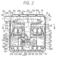
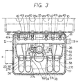
- Lufteinlaßeinheit für einen Verbrennungsmotor, die die folgenden Bauteile aufweist:dadurch gekennzeichnet, daßeinen Luftfilter (21) zum Filtern von Luft, die an den Verbrennungsmotor (10) geliefert wird,ein Filtergehäuse (12, 13) zur Unterbringung des Luftfilters (21), undeinen Ansaugkrümmer (100) zum Einführen der durch den Luftfilter (21) gefilterten Luft in eine Lufteinlaßöffnung (10a),
der Ansaugkrümmer (100) in dem Filtergehäuse (12, 13) angeordnet ist und zusammen mit dem Filtergehäuse (12, 13) eine Doppelwandkonstruktion bildet, die aus einer Durchlaßwand des Ansaugkrümmers (100), die in einer Innenwand (14) ausgebildet ist, und einer Wand des Filtergehäuses (12, 13) die in einer Außenwand (16) ausgebildet ist, zusammengesetzt ist, wobei eine Geräusche-und-Wärme-Isolationsschicht (18) zwischen der Innenwand (14) und der Außenwand (16) angeordnet ist. - Lufteinlaßeinheit gemäß Anspruch 1, dadurch gekennzeichnet, daß ein Teil (40, 41) eines Systems zur Lieferung von Kraftstoff an den Motor (10) in dem Gehäuse (12, 13) untergebracht ist.
- Lufteinlaßeinheit gemäß Anspruch 2, dadurch gekennzeichnet, daß der Teil des Systems zur Lieferung von Kraftstoff eine Einspritzdüse (40) zur Einspritzung von Kraftstoff in den Verbrennungsmotor (10) ist.
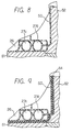
- Lufteinlaßeinheit gemäß einem der Ansprüche 1 bis 3, dadurch gekennzeichnet, daß das Filtergehäuse (12, 13) eine Doppelwandkonstruktion hat, die aus der Innenwand (14, 15) und der Außenwand (16, 17) und einem Geräusch-und-Wärme-Isolationsbauteil (18, 19) zusammengesetzt ist, das zwischen der Innenwand (14, 15) und der Außenwand (16, 17) angeordnet ist.
- Lufteinlaßeinheit gemäß einem der Ansprüche 1 bis 4, dadurch gekennzeichnet, daß das Geräusch-und-Wärme-Isolationsbauteil eine Luftschicht (18, 19) ist.
- Lufteinlaßeinheit gemäß einem der Ansprüche 1 bis 4, dadurch gekennzeichnet, daß das Geräusch-und-Wärme-Isolationsbauteil ein Geräusch-und-Wärme-Isolationsmaterial ist, das zwischen der Innenwand (14, 15) und der Außenwand (16, 17) eingefüllt ist.
- Lufteinlaßeinheit gemäß einem der Ansprüche 1 bis 4 und 6, dadurch gekennzeichnet, daß die Geräusch-und-Wärme-Isolationsschicht aus einem geschäumten Material hergestellt ist.
- Lufteinlaßeinheit gemäß Anspruch 7, dadurch gekennzeichnet, daß die Geräusch-und-Wärme-Isolationsschicht ein Bauteil aufweist, das aus einem geschäumten Material hergestellt ist, das an das Filtergehäuse (12, 13) angeklebt ist.
- Lufteinlaßeinheit gemäß Anspruch 7, dadurch gekennzeichnet, daß die Geräusch-und-Wärme-Isolationsschicht aus einem geschäumten Material hergestellt ist, wenn das Filtergehäuse (12, 13) gebildet wird.
- Lufteinlaßeinheit gemäß einem der voranstehenden Ansprüche 1 bis 9, des weiteren gekennzeichnet durch
eine Auslaßleitung (24), die in dem Filtergehäuse zur Einführung der durch den Luftfilter (21) gefilterten Luft angeordnet ist, wobei die Auslaßleitung (24) eine Filterabstützung (22) an ihrem offenen Ende hat, die den Luftfilter (21) getrennt von dem Filtergehäuse (12, 13) abnehmbar abstützt. - Lufteinlaßeinheit gemäß Anspruch 10, dadurch gekennzeichnet, daß
in dem Filtergehäuse eine Drosselklappe (25) untergebracht ist, die mit der Auslaßleitung (24) und dem Ansaugkrümmer (100) verbunden ist. - Lufteinlaßeinheit gemäß Anspruch 11, dadurch gekennzeichnet, daß
der Luftfilter (21) und die Filterabstützung (22) an einem oberen Abschnitt des Filtergehäuses (12, 13) angeordnet sind, und
die Auslaßleitung (24), die Drosselklappe (25) und der Ansaugkrümmer (100) in dem Filtergehäuse (12, 13) tiefer als der Luftfilter (21) und die Filterabstützung (22) angeordnet sind. - Lufteinlaßeinheit gemäß einem der Ansprüche 10 bis 12, dadurch gekennzeichnet, daß
der Luftfilter (21) ein Filterbauteil (21a) zum Filtern der Ansaugluft und einen Flanschabschnitt (21b) hat, der sich von einem äußeren Umfang des Filterbauteils (21a) nach außen erstreckt,
die Filterabstützung (22) einen Flanschabschnitt (22a) hat, und
der Flanschabschnitt (21b) des Luftfilters (21) abnehmbar durch eine Klemme (23) an dem Flanschabschnitt (22a) der Filterabstützung (22) befestigt ist. - Lufteinlaßeinheit gemäß einem der Ansprüche 10 bis 12, dadurch gekennzeichnet, daß
der Luftfilter (21) ein Filterbauteil (21a) zum Filtern von Ansaugluft und einen Flanschabschnitt (21b) hat, der sich von einem äußeren Umfang des Filterbauteils (21a) nach außen erstreckt;
die Filterabstützung (22) eine Nut (22d) an einem inneren Umfang hat; und
der Flanschabschnitt (21b) des Luftfilters (21) elastisch in die Nut (22d) eingepaßt ist.
Applications Claiming Priority (7)
| Application Number | Priority Date | Filing Date | Title |
|---|---|---|---|
| JP31195096 | 1996-11-22 | ||
| JP311950/96 | 1996-11-22 | ||
| JP31195096 | 1996-11-22 | ||
| JP31394796 | 1996-11-25 | ||
| JP313947/96 | 1996-11-25 | ||
| JP31394796 | 1996-11-25 | ||
| PCT/JP1997/004222 WO1998022705A1 (fr) | 1996-11-22 | 1997-11-19 | Dispositif d'admission d'un moteur a combustion interne |
Publications (3)
| Publication Number | Publication Date |
|---|---|
| EP0892169A1 EP0892169A1 (de) | 1999-01-20 |
| EP0892169A4 EP0892169A4 (de) | 2000-06-28 |
| EP0892169B1 true EP0892169B1 (de) | 2002-06-12 |
Family
ID=26566962
Family Applications (1)
| Application Number | Title | Priority Date | Filing Date |
|---|---|---|---|
| EP97912519A Expired - Lifetime EP0892169B1 (de) | 1996-11-22 | 1997-11-19 | Lufteinlass für verbrennungsmotor |
Country Status (4)
| Country | Link |
|---|---|
| US (1) | US6024188A (de) |
| EP (1) | EP0892169B1 (de) |
| DE (1) | DE59707508D1 (de) |
| WO (1) | WO1998022705A1 (de) |
Cited By (1)
| Publication number | Priority date | Publication date | Assignee | Title |
|---|---|---|---|---|
| DE10348361B4 (de) * | 2003-10-17 | 2016-02-04 | Volkswagen Ag | Saugrohr für eine Brennkraftmaschine |
Families Citing this family (21)
| Publication number | Priority date | Publication date | Assignee | Title |
|---|---|---|---|---|
| KR100331454B1 (ko) | 1998-09-01 | 2002-04-09 | 신구 이이치 | 다기통 내연기관에 있어서의 관성과급식 흡기매니폴드의 구조및 이 흡기매니폴드에 있어서의 브랜치파이프의 접합방법 |
| US6267092B1 (en) * | 1998-11-06 | 2001-07-31 | Honda Giken Kogyo Kabushiki Kaisha | Suction apparatus of multi-cylinder internal combustion engine |
| DE19856044B4 (de) * | 1998-12-04 | 2007-12-06 | Volkswagen Ag | Kraftfahrzeug-Aggregateraum mit einem Dämpferfilter |
| US6263850B1 (en) | 1999-08-03 | 2001-07-24 | Visteon Global Technologies, Inc. | Integrated air induction module for gasoline engines |
| US6308686B1 (en) * | 1999-11-18 | 2001-10-30 | Siemens Canada Limited | Intake manifold with internal fuel rail and injectors |
| DE10004552A1 (de) * | 2000-02-02 | 2001-08-09 | Mann & Hummel Filter | Saugrohr mit integrierter Abgasrückführung |
| JP4467731B2 (ja) * | 2000-08-09 | 2010-05-26 | 富士重工業株式会社 | 樹脂製チャンバの遮音構造 |
| US6418888B1 (en) * | 2000-10-24 | 2002-07-16 | Siemens Vdo Automotive, Inc. | Ultra sonic or heat staked fastening for air intake manifold active system |
| JP4442847B2 (ja) * | 2000-12-22 | 2010-03-31 | ヤマハ発動機株式会社 | 船外機用エンジンの吸気管長可変装置 |
| JP2002235617A (ja) * | 2001-02-08 | 2002-08-23 | Denso Corp | 吸気装置 |
| US6886532B2 (en) * | 2001-03-13 | 2005-05-03 | Nissan Motor Co., Ltd. | Intake system of internal combustion engine |
| US6705268B2 (en) * | 2001-09-21 | 2004-03-16 | Basf Aktiengesellschaft | Engine noise barrier |
| US6691665B2 (en) * | 2001-10-05 | 2004-02-17 | Ford Global Technologies, Llc | Dual air induction arrangement |
| US6938728B2 (en) * | 2001-12-03 | 2005-09-06 | Siemens Vdo Automotive Inc. | Method and apparatus for attaching a resonance chamber to an air induction component |
| US6510833B1 (en) * | 2001-12-20 | 2003-01-28 | American Diesel & Gas, Inc. | Fuel saving combustion engine insulation method and system |
| US7207307B2 (en) * | 2003-02-13 | 2007-04-24 | Denso Corporation | Intake system and method for producing the same |
| KR100579284B1 (ko) * | 2004-07-06 | 2006-05-11 | 현대자동차주식회사 | 자동차의 가변흡기 시스템 |
| FR2888290B1 (fr) * | 2005-07-07 | 2010-07-30 | Peugeot Citroen Automobiles Sa | Repartiteur d'admission d'air et moteur a combustion interne avec un tel repartiteur |
| EP1916161B1 (de) * | 2006-10-20 | 2011-01-12 | MANN+HUMMEL GmbH | Filtersystem für eine Brennkraftmaschine in einem Kraftfahrzeug |
| JP5832111B2 (ja) * | 2011-03-17 | 2015-12-16 | 株式会社セキソー | 吸気ダクト |
| DE102013113214A1 (de) * | 2013-11-29 | 2015-06-03 | Dr. Ing. H.C. F. Porsche Aktiengesellschaft | Sauganordnung für einen Verbrennungsmotor |
Family Cites Families (19)
| Publication number | Priority date | Publication date | Assignee | Title |
|---|---|---|---|---|
| JPS52124309U (de) * | 1976-03-18 | 1977-09-21 | ||
| JPS58173657U (ja) * | 1982-05-15 | 1983-11-19 | 株式会社明電舎 | エレベ−タの速度制御装置 |
| JPS58173756U (ja) * | 1982-05-17 | 1983-11-19 | 富士ロビン株式会社 | エンジンの吸気部構造 |
| DE3707617A1 (de) * | 1987-03-10 | 1988-09-22 | Audi Ag | Ansaugrohr fuer eine brennkraftmaschine |
| JPH0183157U (de) * | 1987-11-24 | 1989-06-02 | ||
| JPH0645656Y2 (ja) * | 1988-05-31 | 1994-11-24 | 株式会社土屋製作所 | エアクリーナ |
| JPH0240963U (de) * | 1988-09-14 | 1990-03-20 | ||
| JPH0269057U (de) * | 1988-11-11 | 1990-05-25 | ||
| JP2521714Y2 (ja) * | 1988-12-28 | 1997-01-08 | 株式会社土屋製作所 | エアクリーナ |
| EP0435588A3 (en) * | 1989-12-27 | 1992-06-24 | Cadillac Rubber & Plastics, Inc. | Air intake duct and method for making same |
| JPH03260366A (ja) * | 1990-03-09 | 1991-11-20 | Suzuki Motor Corp | 自動二輪車のエアークリーナー |
| SE467670B (sv) * | 1991-07-08 | 1992-08-24 | Volvo Ab | Anordning vid foerbraenningsmotor med braensleinsprutning |
| JPH0557352U (ja) * | 1991-12-27 | 1993-07-30 | 株式会社土屋製作所 | エアクリーナ |
| US5269143A (en) * | 1992-12-07 | 1993-12-14 | Ford Motor Company | Diesel engine turbo-expander |
| US5538571A (en) * | 1993-12-01 | 1996-07-23 | Asahi Tec Corporation | Method of manufacturing hollow resin molding |
| DE4402048A1 (de) * | 1994-01-25 | 1995-07-27 | Mann & Hummel Filter | Integriertes Ansaugsystem |
| JP3473642B2 (ja) * | 1994-09-20 | 2003-12-08 | 株式会社デンソー | 燃料噴射装置 |
| US5575247A (en) * | 1995-02-01 | 1996-11-19 | Nippondenso Co., Ltd. | Air intake device for an internal combustion engine |
| JP3356241B2 (ja) * | 1995-02-01 | 2002-12-16 | 株式会社デンソー | 内燃機関の吸気装置 |
-
1997
- 1997-11-19 WO PCT/JP1997/004222 patent/WO1998022705A1/ja active IP Right Grant
- 1997-11-19 EP EP97912519A patent/EP0892169B1/de not_active Expired - Lifetime
- 1997-11-19 DE DE59707508T patent/DE59707508D1/de not_active Expired - Fee Related
-
1998
- 1998-05-20 US US09/081,789 patent/US6024188A/en not_active Expired - Fee Related
Cited By (1)
| Publication number | Priority date | Publication date | Assignee | Title |
|---|---|---|---|---|
| DE10348361B4 (de) * | 2003-10-17 | 2016-02-04 | Volkswagen Ag | Saugrohr für eine Brennkraftmaschine |
Also Published As
| Publication number | Publication date |
|---|---|
| EP0892169A1 (de) | 1999-01-20 |
| US6024188A (en) | 2000-02-15 |
| WO1998022705A1 (fr) | 1998-05-28 |
| DE59707508D1 (de) | 2002-07-18 |
| EP0892169A4 (de) | 2000-06-28 |
Similar Documents
| Publication | Publication Date | Title |
|---|---|---|
| EP0892169B1 (de) | Lufteinlass für verbrennungsmotor | |
| DE69915764T2 (de) | Lüftergehäuse und Lufteinlassanordnung | |
| DE602006000983T2 (de) | Einlasskrümmer aus Kunststoff | |
| EP0664390B1 (de) | Integriertes Ansaugsystem | |
| DE2649043A1 (de) | Kompressoraggregat | |
| DE602004006661T2 (de) | Brennkraftmaschine mit Entlüftungsvorrichtung | |
| EP0631043B1 (de) | Aktivkohlefilter zur Kraftstofftankentlüftung | |
| DE10036241A1 (de) | Integriertes Luftansaugmodul für Benzinmotoren | |
| WO2005095783A1 (de) | Ansaugfilter für eine brennkraftmaschine eines fahrzeugs | |
| DE4403219A1 (de) | Als Baueinheit vorfertigbares Saugmodul für eine Mehrzylnder-Brennkraftmaschine | |
| DE4202077A1 (de) | Ansaugverteiler fuer eine brennkraftmaschine | |
| DE102010020064B4 (de) | Schalldämpferanordnung für eine insbesondere aufgeladene Kraftfahrzeug-Brennkraftmaschine | |
| EP0891486B1 (de) | Ansaugsystem für einen verbrennungsmotor | |
| DE102013020286A1 (de) | Filtervorrichtung für Fluid und Trägerelement für wenigstens ein Filterelement | |
| DE19546545B4 (de) | Saugrohrmodul | |
| EP0879350A1 (de) | Luftführungsanlage | |
| EP1520977B1 (de) | Ansaugvorrichtung für eine Vorreinigungseinrichtung in Verbindung mit einer Ventilatorverkleidung | |
| DE10212407A1 (de) | Tankinternes Kraftstoffpumpensystem | |
| EP1422413B1 (de) | Ansaugsystem | |
| DE19753390A1 (de) | Stapelförmig angeordneter, schneckenförmiger Krümmer | |
| DE10243883A1 (de) | Resonatorluftfilter | |
| DE102011103429B4 (de) | Staubfilter | |
| DE2900787A1 (de) | Luftansaugsystem fuer eine diesel- brennkraftmaschine | |
| DE102021112122A1 (de) | Filterelement für ein Filtersystem mit einer Resonatorstruktur und Filtersystem mit einer Resonatorstruktur | |
| DE102020127763A1 (de) | Luftfiltervorrichtung in einem luftansaugsystem für einen motor und verfahren zur verwendung der vorrichtung |
Legal Events
| Date | Code | Title | Description |
|---|---|---|---|
| PUAI | Public reference made under article 153(3) epc to a published international application that has entered the european phase |
Free format text: ORIGINAL CODE: 0009012 |
|
| 17P | Request for examination filed |
Effective date: 19981102 |
|
| AK | Designated contracting states |
Kind code of ref document: A1 Designated state(s): DE |
|
| K1C1 | Correction of patent application (title page) published |
Effective date: 19990120 |
|
| A4 | Supplementary search report drawn up and despatched |
Effective date: 20000509 |
|
| AK | Designated contracting states |
Kind code of ref document: A4 Designated state(s): DE |
|
| 17Q | First examination report despatched |
Effective date: 20000914 |
|
| GRAG | Despatch of communication of intention to grant |
Free format text: ORIGINAL CODE: EPIDOS AGRA |
|
| GRAG | Despatch of communication of intention to grant |
Free format text: ORIGINAL CODE: EPIDOS AGRA |
|
| GRAH | Despatch of communication of intention to grant a patent |
Free format text: ORIGINAL CODE: EPIDOS IGRA |
|
| GRAH | Despatch of communication of intention to grant a patent |
Free format text: ORIGINAL CODE: EPIDOS IGRA |
|
| GRAA | (expected) grant |
Free format text: ORIGINAL CODE: 0009210 |
|
| AK | Designated contracting states |
Kind code of ref document: B1 Designated state(s): DE |
|
| REF | Corresponds to: |
Ref document number: 59707508 Country of ref document: DE Date of ref document: 20020718 |
|
| PLBE | No opposition filed within time limit |
Free format text: ORIGINAL CODE: 0009261 |
|
| STAA | Information on the status of an ep patent application or granted ep patent |
Free format text: STATUS: NO OPPOSITION FILED WITHIN TIME LIMIT |
|
| 26N | No opposition filed |
Effective date: 20030313 |
|
| PGFP | Annual fee paid to national office [announced via postgrant information from national office to epo] |
Ref country code: DE Payment date: 20051117 Year of fee payment: 9 |
|
| PG25 | Lapsed in a contracting state [announced via postgrant information from national office to epo] |
Ref country code: DE Free format text: LAPSE BECAUSE OF NON-PAYMENT OF DUE FEES Effective date: 20070601 |