EP0892431A2 - Heat radiating plate - Google Patents
Heat radiating plate Download PDFInfo
- Publication number
- EP0892431A2 EP0892431A2 EP98112303A EP98112303A EP0892431A2 EP 0892431 A2 EP0892431 A2 EP 0892431A2 EP 98112303 A EP98112303 A EP 98112303A EP 98112303 A EP98112303 A EP 98112303A EP 0892431 A2 EP0892431 A2 EP 0892431A2
- Authority
- EP
- European Patent Office
- Prior art keywords
- heat radiating
- radiating fins
- heat
- heat transfer
- transfer plate
- Prior art date
- Legal status (The legal status is an assumption and is not a legal conclusion. Google has not performed a legal analysis and makes no representation as to the accuracy of the status listed.)
- Granted
Links
Images


Classifications
-
- H—ELECTRICITY
- H01—ELECTRIC ELEMENTS
- H01L—SEMICONDUCTOR DEVICES NOT COVERED BY CLASS H10
- H01L23/00—Details of semiconductor or other solid state devices
- H01L23/34—Arrangements for cooling, heating, ventilating or temperature compensation ; Temperature sensing arrangements
- H01L23/36—Selection of materials, or shaping, to facilitate cooling or heating, e.g. heatsinks
- H01L23/367—Cooling facilitated by shape of device
- H01L23/3672—Foil-like cooling fins or heat sinks
-
- F—MECHANICAL ENGINEERING; LIGHTING; HEATING; WEAPONS; BLASTING
- F28—HEAT EXCHANGE IN GENERAL
- F28F—DETAILS OF HEAT-EXCHANGE AND HEAT-TRANSFER APPARATUS, OF GENERAL APPLICATION
- F28F13/00—Arrangements for modifying heat-transfer, e.g. increasing, decreasing
- F28F13/06—Arrangements for modifying heat-transfer, e.g. increasing, decreasing by affecting the pattern of flow of the heat-exchange media
- F28F13/12—Arrangements for modifying heat-transfer, e.g. increasing, decreasing by affecting the pattern of flow of the heat-exchange media by creating turbulence, e.g. by stirring, by increasing the force of circulation
-
- F—MECHANICAL ENGINEERING; LIGHTING; HEATING; WEAPONS; BLASTING
- F28—HEAT EXCHANGE IN GENERAL
- F28F—DETAILS OF HEAT-EXCHANGE AND HEAT-TRANSFER APPARATUS, OF GENERAL APPLICATION
- F28F3/00—Plate-like or laminated elements; Assemblies of plate-like or laminated elements
- F28F3/02—Elements or assemblies thereof with means for increasing heat-transfer area, e.g. with fins, with recesses, with corrugations
-
- H—ELECTRICITY
- H01—ELECTRIC ELEMENTS
- H01L—SEMICONDUCTOR DEVICES NOT COVERED BY CLASS H10
- H01L23/00—Details of semiconductor or other solid state devices
- H01L23/34—Arrangements for cooling, heating, ventilating or temperature compensation ; Temperature sensing arrangements
- H01L23/46—Arrangements for cooling, heating, ventilating or temperature compensation ; Temperature sensing arrangements involving the transfer of heat by flowing fluids
- H01L23/467—Arrangements for cooling, heating, ventilating or temperature compensation ; Temperature sensing arrangements involving the transfer of heat by flowing fluids by flowing gases, e.g. air
-
- F—MECHANICAL ENGINEERING; LIGHTING; HEATING; WEAPONS; BLASTING
- F28—HEAT EXCHANGE IN GENERAL
- F28F—DETAILS OF HEAT-EXCHANGE AND HEAT-TRANSFER APPARATUS, OF GENERAL APPLICATION
- F28F2215/00—Fins
- F28F2215/10—Secondary fins, e.g. projections or recesses on main fins
-
- H—ELECTRICITY
- H01—ELECTRIC ELEMENTS
- H01L—SEMICONDUCTOR DEVICES NOT COVERED BY CLASS H10
- H01L2924/00—Indexing scheme for arrangements or methods for connecting or disconnecting semiconductor or solid-state bodies as covered by H01L24/00
- H01L2924/0001—Technical content checked by a classifier
- H01L2924/0002—Not covered by any one of groups H01L24/00, H01L24/00 and H01L2224/00
-
- H—ELECTRICITY
- H01—ELECTRIC ELEMENTS
- H01L—SEMICONDUCTOR DEVICES NOT COVERED BY CLASS H10
- H01L2924/00—Indexing scheme for arrangements or methods for connecting or disconnecting semiconductor or solid-state bodies as covered by H01L24/00
- H01L2924/30—Technical effects
- H01L2924/301—Electrical effects
- H01L2924/3011—Impedance
Definitions
- the present invention relates to a heat radiating plate which dissipates heat generated by a heat generating element such as a semiconductor device.
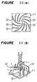
- FIG 11 a conventional heat radiating plate which has been disclosed in e.g. JP-U-629148.
- a view (a) is an a plan view of the conventional heat radiating plate
- a view (b) is a perspective view to explain cooling function under natural air-cooling.
- reference numeral 11 designates a heat transfer plate.
- the heat transfer plate 11 is prepared by cutting a rolled plate of high heat conductive aluminum alloy into a rectangular shape.
- the heat transfer plate is formed in a flat shape to have a slightly smaller contour than the top surface of a semiconductor device package to be coupled.
- Reference numeral 12 designates heat radiating fins.
- the heat radiating fins 12 are prepared by molding a material of aluminum alloy similar to the heat radiating plate 11 by extrusion so as to have a shaped section and cutting the molded material at a certain length.
- Each of the heat radiating fins is formed in such a curved shape so that it has a horizontal section formed so as to have a curvature which forms a part of a scroll directed from a peripheral portion to the center of the heat transfer plate 11 and it has a vertical section without a projection.
- the heat radiation fins are arranged in a radial pattern along respective scrolls directed to the center of the heat transfer plate 11 and are spaced with intervals therebetween without joining and contacting together at a central portion of the heat transfer plate.
- the heat radiating fins are bonded on the heat transfer plate 11 by a high heat conductive adhesive.
- the conventional heat radiating plate Since the conventional heat radiating plate is constructed as stated earlier and works under natural air-cooling, the conventional heat radiating plate has created a problem in that increased dissipation of heat requires enlargement of the heat transfer plate or increased height of the heat radiating fins, preventing the entire heat radiating plate from being compact.
- the arrangement of the heat radiating fins in the conventional heat radiating plate has a significant resistance to the air current between the heat radiating fins, creating a problem in that it is difficult to obtain good heat radiating efficiency.
- a heat radiating plate wherein a plurality of heat radiating fins are formed on a surface of a heat transfer plate, wherein the heat radiating fins are formed in a curved shape and are arranged in a radial pattern on the heat transfer plate, and wherein a space is provided on the surface of the heat transfer plate so as to be surrounded by inward edges of the heat radiating fins.
- the heat radiating fins have a sidewall formed with a plurality of projections in the first aspect.
- the projections on the sidewall of a heat radiating fin are staggered with respect to the projections on an opposed sidewall of an adjacent heat radiating fin in the second aspect.
- the projections have a height gradually increased from an inward portion toward an outward portion of the heat radiating fins in the second aspect.
- the projections are formed on inner and outer sidewalls of the heat radiating fins, and the projections on the inner sidewalls are higher than those on the outer sidewalls in the second aspect.
- the heat radiating fins are arranged on the heat transfer plate so that the heat radiating fins have the respective inward edges located on an imaginary circle on the heat transfer plate in the first aspect.
- the heat radiating fins are arranged on the heat transfer plate so that the heat radiating fins have respective outward edges located on an imaginary circle in the first aspect.
- the heat radiating fins are arranged on the heat transfer plate so that the heat radiating fins have the respective inward edges located on a first imaginary circle and respective outward edges located a second imaginary circle having a greater diameter than the first imaginary circle in the first aspect.
- the transfer plate is formed in a circular shape which is concentric with the imaginary circles of the inward and outward edges of the heat radiating fins in the eighth aspect.
- the heat radiating fins have a smaller thickness than the heat transfer plate in the first aspect.
- the resistance to the air current flowing between the heat radiating fins can be minimized to increase the current speed on the heat radiating fins.
- Supply of air from the space into gaps between the heat radiating fins and suction form the gaps between the heat radiating fins into the space can be effectively carried out to provide an increased heat radiating effect, making the heat radiating plate small and lightweight.
- a vortex can be generated on a downstream side of each of the projections to improve a heat transfer rate, providing a further increased heat radiating effect.
- the heat transfer rate of the entire heat radiating fins can be raised to improve the heat radiating effect.
- the heat transfer rate on the outward portion where the current speed is low can be raised to improve the heat radiating effect.
- the strong air which fits against on the inner sidewalls can be diffused toward the outer sidewalls to increase the heat radiating effect.
- the resistance to the air which enters between the heat radiating fins can be minimized, or a discharge of air can be equalized to improve the heat radiating effect.
- the discharge of air can be equalized or the resistance to the air which enters between the heat radiating fins can be minimized to improve the heat radiating effect.
- the heat radiating fins can be respective lengths equalized to avoid generation of a temperature difference, not only improving the heat radiating effect but also preventing noise from occurring.
- the heat transfer can be equalized not only to improve the heat radiating effect but also to make the heat radiating plate smaller.
- the heat radiating effect can be further improved.
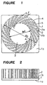
- FIG 1 a plan view of the heat radiating plate according to a first embodiment of the present invention.
- Figure 2 is shown a side view of the heat radiating plate.
- reference numeral 1 designates a heat transfer plate which is made of aluminum alloy and is formed in a substantially square shape.
- Reference numeral 1a designates a mounting surface of the heat transfer plate, to which a heat generating element such as a semiconductor device is fixed by a heat conductive adhesive.
- Reference numeral 1b designates a heat radiating surface which is opposite to the mounting surface 1a.
- Reference numeral 2 designates one of heat radiating fins which are made of an aluminum alloy plate like the heat transfer plate 1, which have a smaller thickness than the heat transfer plate 1, and which are arranged on the heat radiating surface 1b of the heat transfer plate 1 so as to extend perpendicularly thereto.
- Reference numeral 3 designates a space which is provided at a substantially central portion on the heat radiating surface 1b without provision of the heat radiating fins 2, and which works as an air inlet stated later on.
- Reference numeral 4 designates one of plural outer projections which project from an outer sidewall 2a of each of the heat radiating fins 2 in a curved shape and are formed in a substantially triangular shape in section.
- Reference numeral 5 designates one of plural inner projections which project from an inner sidewall 2b of each of the heat radiating fins 2 and are formed in a substantially triangular shape in section.
- FIG. 3 is shown a schematic view to explain a forced cooling function.
- Reference numeral 6 designates an electric motor
- reference numeral 7 designates a fan which is arranged to confront the air inlet 3 and which is driven by the electric motor 6 to supply cooling air in a direction B.
- the heat radiating fins 2 are arranged on the heat radiating surface 1b of the heat transfer plate 1 so as to be radially directed from an inner portion toward an outer portion thereof at substantially equal intervals along the entire periphery thereof.
- the heat radiating fins 2 are arranged in an annular shape so that respective inward edges of the heat radiating fins are located on an imaginary circle having a diameter d and so that respective outward edges of the heat radiating fins are located on another imaginary circle having a greater diameter D than the diameter d.
- the respective inward edges of the heat radiating fins 2 confront the air inlet 3.
- the gap between the inward edges of adjacent heat radiating fins 2 works as an inlet C for the cooling air supplied from the fan 7, and the gap between the outward edges of the adjacent heat radiating fins works as an outlet E for the cooling air.
- the outlet E is greater than the inlet C, and the divergent angle from the inlet C toward the outlet E is set at about 14 degree in the shown example to provide the air current with a diffusing effect.
- the heat radiating fins 2 are arranged on the heat radiating surface 1b of the heat transfer plate 1 at a certain angle with respect to the radial direction of the circle on which the respective inward edges of the heat radiating fins 2 are located.
- the heat radiating fins 2 are curved along the flow direction of the cooling air at a certain curvature. In other words, the heat radiating fins are arranged so that there is a relationship between a velocity vector at the outlet (outer diameter) of the fan 7 and the heat radiating fins 2 as shown in Figure 4.
- reference U represents a peripheral velocity of the fan 7 ( ⁇ fan diameter ⁇ fan revolution )
- reference W represents a relative velocity of a discharge current with respect to the fan
- reference V represents an absolute velocity of the discharge current as viewed in terms of the rest frame, at which the discharge current enters the gap between the adjacent heat radiating fins 2 at the absolute velocity V.
- the angle of the inlet C between adjacent heat radiating fins 2 can be set to conform with the angle of the absolute velocity V (the discharge angle of the air A supplied by the fan 7) to minimize the flow resistance at the inlet of the heat radiating fins.
- the discharge current by the fan 7 flows out whirlwinding since it includes a velocity component in the peripheral direction.
- the respective curved heat radiating fins 2 are arranged in a scroll pattern to minimize the flow resistance in the passages defined by the heat radiating fins 2, providing smooth whirling currents.
- the outer projections 4 and the inner projections 5 are formed so that they have a height gradually increased from the side of each of the inlets C toward the side of each of the outlets E.
- the inner projections 5 are formed so that they are higher than the outer projection 4 in the corresponding orders with respect to the inlets.
- the outer projections 4 which project from the outer sidewall 2a of one of adjacent heat radiating fins 2 are staggered with respect to the inner projection 5 which project from the inner sidewall 2b of the other opposed heat radiating fin 2.
- the heat radiating plate may be prepared by forming the heat transfer plate 1 and the heat radiating fins 2 in a one-piece construction, and the production of the heat radiating plate can be carried out by e.g. die-casting, liquid metal forging and forging. It is preferable that the aluminum alloy material has at least 90 wt% of aluminum included therein.
- the aluminum alloy material having such a content of aluminum has a high heat conductivity and provide a smooth flow of molten metal in shaping, making the shaping easy.
- a semiconductor device (not shown) is closely fixed to the mounting surface 1a of the heat transfer plate 1.
- the semiconductor device When the semiconductor device is energized to generate heat, the heat is transferred to the heat radiating fins 2 through the heat transfer plate 1 to heat the heat radiating plate as a whole.
- the fan 7 is driven by the electric motor 6 to supply cooling air to the heat radiating plate, cooling the heat radiating plate.
- the heat transfer rate of a heat radiating plate increases as the air current speed on the heat radiating fins of the heat radiating plate increases. From this standing point, the present invention provides the heat radiating fins 2 with a unique shape and arrangement in order to make the air current speed as fast as possible.
- the cooling air is supplied toward the air inlet 3, arrives at the heat radiating surface 1b, diffuses outwardly, enters the gaps between the heat radiating fins 2 through the inlets C, carries out heat exchange with the heat radiating fins 2, and is exhausted through the outlets E throughout the entire periphery of the heat radiating plate. Because the angle of the inlets C of the heat radiating fins 2 conforms to the discharge angle of the air supplied by the fan 7 as stated earlier, and because the air inlet 3 is formed in a circular shape, the resistance to the air is minimized when entering the inlets C.
- the passages defined by the heat radiating fins 2 have a small resistance to the flows to make the air current speed faster, obtaining a good heat radiating effect. Since the outer edges of the heat radiating fins 2 are located on the other circle, and since the heat radiating fins 2 have an equal length one another, discharge of the air is equalized to make heat resiasion equal. As a result, the respectively heat radiating fins 2 have no temperature difference one another, preventing noise from occurring.
- FIG 5 is shown a schematic view to explain how air flows along the outer sidewall 2a of a heat radiating fin 2.
- the air which was a laminar flow at a point 1 ⁇ , has a portion thereof near to the outer sidewall 2a delayed by viscosity resistance of the outer sidewall 2a in comparison with a portion thereof away from the outer sidewall in terms of current speed (a point 2 ⁇ ).
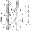
- the fluid flow between normal parallel plates will be explained, referring to Figure 6.
- the flow has such a parabola velocity distribution that it has portions thereof near to wall surfaces decelerated by the viscosity of the wall surfaces and a central portion thereof having the maximum velocity.
- Figure 7 is shown a schematic view of the air flow behind the projection 4 (a downstream side of the air flow).
- the air flow exfoliates at the point 3 ⁇ because of the projection 4 and readheres at a point 4 ⁇ .
- a solid line connecting the points 3 ⁇ and 4 ⁇ represents the exfoliation boundary line of the air flow.
- the vortex Since strong turbulence (vortex) generated on the exfoliation boundary line comes near to the outer sidewall at a location near to the readhering point, the vortex causes strong velocity components to be produced in a direction perpendicular to the surface of the heat radiating fin 2 so that a perpendicular velocity component directed to the surface of the heat radiating fin 2 supplies the surface with cool air of a primary current away of the surface and the remaining perpendicular velocity component supplies the primary current with warm air on the surface. As a result, the heat transfer rate at the location near to the readhering point can be significantly improved.
- the plural projections 4 on a sidewall of a heat radiating fin are staggered with respect to the plural projections 5 on an opposed sidewall of an adjacent heat radiating fin, further improving the heat transfer rate. Since an exfoliation area S surrounded by the exfoliation boundary line has a low heat transfer rate due to no contact with the primary current, and since the transfer rate at a location away from the readhering point toward the downstream side is low due to a decrease in the vortex, a small number of the projections are not enough to improve the entire heat transfer rate though a small number of the projections can locally improve the heat transfer rate.
- the staggered projections 4 and 5 can make each exfoliation region with a low heat transfer rate as narrow as possible, and repeats exfoliation and readhering to narrow portions with no vortex behind readhering points toward the downstream side.
- FIG 8 schematically shown how air flows between opposed heat radiating fins 2.
- the upper heat radiating fin is indicated by the reference numeral 2A
- the lower heat radiating fin is indicated by reference numeral 2B.
- Reference numerals 5a, 5b and 5c designate inner projection which are formed on the inner sidewall 2b of the heat radiating fin 2A.
- Reference numerals 4a and 4b designate outer projections which are formed on the outer sidewall 2a of the heat radiating fin 2B.
- the inner projections 5a, 5b, 5c are arranged so as to stagger with respect to the outer projections 4a, 4b.
- the air currents which have entered from the left side in Figure 8 are deviated toward the lower heat radiating fin 2B by the first inner projection on the heat radiating fin 2A.
- the air currents which have been deviated downward are deviated upward by the first outer projection 4a on the heat radiating fin 2B.
- the air currents which have exfoliated at the first inner projection 5a readhere to the heat radiating fin 2A rapidly.
- Such a phenomenon is repeated by the projections 5a, 5b and 5c on the downstream side.
- the staggering arrangement of the projections on the opposed sidewall of the adjacent heat radiating fins 2 allows the distance from exfoliation to the readhering point of the air currents to be shortened.
- the successive arrangement of the projections can provide the readhering points at a plural locations to remarkably improve the heat transfer rate.
- the pitch between adjacent projections on a single sidewall is required to have such requirements that the air currents can readhere at a location at least between the adjacent projections.
- the requirements are determined by the shape of the projections, the height of the projections, current speed, the distance between the adjacent heat radiating fins, the curvature of the heat radiating fins and so on.
- the surface viscosity of the heat radiating fins 2 causes the current speed to decrease, lowering heat recovery.
- the provision of the outer and inner projections 4 and 5 can increase the heat transfer rate since the outer projections 4 and the inner projections 5 have a height thereof gradually increased toward the outer side of the heat radiating plate.
- the air which is passing between the opposed heat radiating fins 2 includes a strong portion on the side of the inner sidewall 2b of the upper heat radiating fin 2 and a weak portion on the side of the outer sidewall 2a of the lower heat radiating fin, the inner projections 5 are formed so as to be higher than the outer projections 4 in corresponding orders from the air inlet. As a result, the strong portion of the air which hits against the inner sidewall 2b is diffused toward the outer sidewall 2a, improving the heat radiating effect.
- the heat radiating fins 2 are thinner than the heat radiating plate 1, the heat which has been absorbed from the heat generating element by the heat radiating plate 1 can be easily diffused through the heat radiating fins 2, providing good heat radiating efficiency.
- the reduced thickness of the heat radiating fins 2 can increase the number of the heat radiating fins 2 keeping a required opening ratio for the inlets C of the cooling air. As a result, the heat radiating effect can be improved.
- each of the heat radiating fins 2 which is obtained by being cutting at a plane parallel with the heat transfer rate 1 is greater than the cross-sectional area of heat radiating pins which are arranged at plural positions on a portion where each of the heat radiating fins occupies.
- the provision of the heat radiating fins can provide good heat conduction and a good heat radiating effect.
- the cross-sectional shape of the projections is triangular in the first embodiment, the cross-sectional shape may be semicircular as shown in Figure 9a, quarter circular as shown in Figure 9b, rectangular as shown in Figure 9c and trapezoidal as shown in Figure 9d. whatever shape the projections have, a similar effect can be obtained as long as the projections project from the heat radiating fins 2.
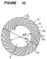
- FIG 10 is shown a plan view of the heat radiating plate in accordance with a third embodiment.
- the plane shape of the heat transfer plate 1 is circular like the outer periphery of the heat radiating fins 2. Such a shape can equalize the heat transfer from the heat transfer plate 1 to the heat radiating fins 2, further improving the heat radiating effect. If the heat transfer plate 1 has the same diameter of the outer periphery of the heat radiating fins 2 as shown in Figure 10, the heat radiating plate can be made smaller.
- the shape of the heat transfer plate 1 is not limited to the example stated earlier.
- the shape of the heat transfer plate may be rectangular.
- the heat radiating fins 2 may be arranged so as to occupy a location shifted from the central portion of the heat transfer plate 1.
Abstract
Description
Claims (10)
- A heat radiating plate comprising:a heat transfer plate (1); anda plurality of heat radiating fins (2) formed on a surface (1b) of the heat transfer plate;
wherein the heat radiating fins are formed in a curved shape and are arranged in a radial pattern on the heat transfer plate, and wherein a space (3) is provided on the surface of the heat transfer plate so as to be surrounded by inward edges of the heat radiating fins. - The heat radiating plate according to Claim 1, wherein the heat radiating fins have a side wall formed with a plurality of projections (4, 5).
- The heat radiating plate according to Claim 2, wherein the projections on the side wall (2a) of a heat radiating fin are staggered with respect to the projections on an opposed side wall (2b) of an adjacent heat radiating fins.
- The heat radiating plate according to Claim 2, wherein the projections have a height thereof gradually increased from an inward portion toward an outward portion of the heat radiating fins.
- The heat radiating plate according to Claim 2, wherein the projections are formed on inner and outer side walls of the heat radiating fins, and the projections on the inner side walls are higher than those on the outer side walls.
- The heat radiating plate according to Claim 1, wherein the heat radiating fins are arranged on the heat transfer plate so that the heat radiating fins have the respective inward edges located on a first imaginary circle on the heat transfer plate.
- The heat radiating plate according to Claim 1, wherein the heat radiating fins are arranged on the heat transfer plate so that the heat radiating fins have respective outward edges located on a second imaginary circle on the heat transfer plate.
- The heat radiating plate according to Claim 1, wherein the heat radiating fins are arranged on the heat transfer plate so that the heat radiating fins have the respective inward edges located on a first imaginary circle on the heat transfer plate, and so that the heat radiating fins have respective outward edges located on a second imaginary circle on the heat transfer plate, the second imaginary circle having a greater diameter than that the first imaginary circle.
- The heat radiating plate according to Claim 8, wherein the heat transfer plate is formed in a circular shape which is concentric with the first and second imaginary circles.
- The heat radiating plate according to Claim 1, wherein the heat radiating fins have a smaller thickness than the heat transfer plate.
Applications Claiming Priority (3)
| Application Number | Priority Date | Filing Date | Title |
|---|---|---|---|
| JP18799797 | 1997-07-14 | ||
| JP187997/97 | 1997-07-14 | ||
| JP18799797A JP3352362B2 (en) | 1997-07-14 | 1997-07-14 | Heat sink |
Publications (3)
| Publication Number | Publication Date |
|---|---|
| EP0892431A2 true EP0892431A2 (en) | 1999-01-20 |
| EP0892431A3 EP0892431A3 (en) | 2000-08-02 |
| EP0892431B1 EP0892431B1 (en) | 2009-09-16 |
Family
ID=16215837
Family Applications (1)
| Application Number | Title | Priority Date | Filing Date |
|---|---|---|---|
| EP98112303A Expired - Lifetime EP0892431B1 (en) | 1997-07-14 | 1998-07-02 | Heat radiating plate |
Country Status (7)
| Country | Link |
|---|---|
| US (1) | US6015008A (en) |
| EP (1) | EP0892431B1 (en) |
| JP (1) | JP3352362B2 (en) |
| KR (1) | KR100377652B1 (en) |
| CN (1) | CN1127762C (en) |
| DE (1) | DE69841150D1 (en) |
| TW (1) | TW390005B (en) |
Cited By (3)
| Publication number | Priority date | Publication date | Assignee | Title |
|---|---|---|---|---|
| DE19934554A1 (en) * | 1999-07-22 | 2001-01-25 | Michael Stollenwerk | Heat exchanger has cooling body with channel structure for introducing the cooling medium |
| WO2001061751A2 (en) | 2000-02-18 | 2001-08-23 | Intel Corporation | Parallel-plate/pin-fin hybrid copper heat sink for cooling high-powered microprocessor |
| CN100453823C (en) * | 2006-03-06 | 2009-01-21 | 张炜 | Miniature heat-collecting pump |
Families Citing this family (53)
| Publication number | Priority date | Publication date | Assignee | Title |
|---|---|---|---|---|
| US7220782B1 (en) | 1999-02-26 | 2007-05-22 | University Of Iowa Research Foundation | Methods to reduce the sensitivity of endothelially-compromised vascular smooth muscle |
| US7393864B2 (en) | 1999-02-26 | 2008-07-01 | University Of Iowa Research Foundation | Use of ClC3 chloride channel blockers to modulate vascular tone |
| US6349760B1 (en) | 1999-10-22 | 2002-02-26 | Intel Corporation | Method and apparatus for improving the thermal performance of heat sinks |
| US6244331B1 (en) * | 1999-10-22 | 2001-06-12 | Intel Corporation | Heatsink with integrated blower for improved heat transfer |
| KR100688235B1 (en) * | 2000-05-31 | 2007-02-28 | 한라공조주식회사 | Cooling plate structure of electric heat sink |
| KR20020019743A (en) * | 2000-09-06 | 2002-03-13 | 김봉기, 김선기 | A card settling system for electronic commerce |
| US6796370B1 (en) * | 2000-11-03 | 2004-09-28 | Cray Inc. | Semiconductor circular and radial flow cooler |
| JP3686005B2 (en) * | 2001-03-30 | 2005-08-24 | 山洋電気株式会社 | Cooling device with heat sink |
| US6418020B1 (en) * | 2001-03-30 | 2002-07-09 | Advanced Thermal Technologies | Heat dissipation device with ribbed fin plates |
| US6671172B2 (en) * | 2001-09-10 | 2003-12-30 | Intel Corporation | Electronic assemblies with high capacity curved fin heat sinks |
| KR100450326B1 (en) * | 2002-01-22 | 2004-09-30 | 성이제 | Heat sink construction of largest radiant heat area |
| US6847525B1 (en) * | 2002-05-24 | 2005-01-25 | Unisys Corporation | Forced convection heat sink system with fluid vector control |
| US6830097B2 (en) | 2002-09-27 | 2004-12-14 | Modine Manufacturing Company | Combination tower and serpentine fin heat sink device |
| US20040200608A1 (en) * | 2003-04-11 | 2004-10-14 | Baldassarre Gregg J. | Plate fins with vanes for redirecting airflow |
| US6937473B2 (en) * | 2003-06-30 | 2005-08-30 | Intel Corporation | Heatsink device and method |
| GB2406442A (en) * | 2003-09-24 | 2005-03-30 | Giga Byte Tech Co Ltd | Heat sink |
| US7290598B2 (en) * | 2004-02-26 | 2007-11-06 | University Of Rochester | Heat exchange device |
| US20060011324A1 (en) * | 2004-07-13 | 2006-01-19 | Rogers C J | Wound, louvered fin heat sink device |
| US20060021736A1 (en) * | 2004-07-29 | 2006-02-02 | International Rectifier Corporation | Pin type heat sink for channeling air flow |
| TWI274538B (en) * | 2004-11-12 | 2007-02-21 | Asustek Comp Inc | Heat sink structure |
| US7269011B2 (en) * | 2005-08-04 | 2007-09-11 | Delphi Technologies, Inc. | Impingement cooled heat sink with uniformly spaced curved channels |
| US7278468B2 (en) * | 2005-10-04 | 2007-10-09 | Delphi Technologies, Inc. | Heat sink with multiple coolant inlets |
| US7896611B2 (en) * | 2007-01-03 | 2011-03-01 | International Business Machines Corporation | Heat transfer device in a rotating structure |
| US7760506B1 (en) * | 2007-06-06 | 2010-07-20 | Hewlett-Packard Development Company, L.P. | Electronic components, systems and apparatus with air flow devices |
| US8033325B2 (en) * | 2007-07-24 | 2011-10-11 | Asia Vital Components Co., Ltd. | Heat dissipation apparatus with coarse surface capable of intensifying heat transfer |
| US20090321046A1 (en) * | 2008-06-30 | 2009-12-31 | Alcatel-Lucent Technologies Inc. | Flow diverters to enhance heat sink performance |
| US8248809B2 (en) * | 2008-08-26 | 2012-08-21 | GM Global Technology Operations LLC | Inverter power module with distributed support for direct substrate cooling |
| US20100108292A1 (en) * | 2008-10-31 | 2010-05-06 | Teledyne Scientific & Imaging, Llc | Heat sink system with fin structure |
| KR101000020B1 (en) | 2008-10-31 | 2010-12-10 | 한국과학기술원 | Heat sink |
| US20100170657A1 (en) * | 2009-01-06 | 2010-07-08 | United Technologies Corporation | Integrated blower diffuser-fin heat sink |
| US8068338B1 (en) | 2009-03-24 | 2011-11-29 | Qlogic, Corporation | Network device with baffle for redirecting cooling air and associated methods |
| KR100938290B1 (en) * | 2009-07-31 | 2010-01-22 | (주) 이노밴 | Heat sink for lighting apparatus |
| US8169779B2 (en) * | 2009-12-15 | 2012-05-01 | GM Global Technology Operations LLC | Power electronics substrate for direct substrate cooling |
| TWI400420B (en) * | 2010-01-20 | 2013-07-01 | Asia Vital Components Co Ltd | Spiral heat exchanger |
| US10103089B2 (en) | 2010-03-26 | 2018-10-16 | Hamilton Sundstrand Corporation | Heat transfer device with fins defining air flow channels |
| US10852069B2 (en) | 2010-05-04 | 2020-12-01 | Fractal Heatsink Technologies, LLC | System and method for maintaining efficiency of a fractal heat sink |
| US10041745B2 (en) | 2010-05-04 | 2018-08-07 | Fractal Heatsink Technologies LLC | Fractal heat transfer device |
| US9228785B2 (en) | 2010-05-04 | 2016-01-05 | Alexander Poltorak | Fractal heat transfer device |
| US8295046B2 (en) * | 2010-07-19 | 2012-10-23 | Hamilton Sundstrand Corporation | Non-circular radial heat sink |
| US20220120517A1 (en) * | 2011-05-12 | 2022-04-21 | Fractal Heatsink Technologies LLC | Fractal heat transfer device |
| AT515828B1 (en) * | 2014-05-23 | 2022-02-15 | Fronius Int Gmbh | Cooling device and inverter housing with such a cooling device |
| US10506735B2 (en) | 2014-08-25 | 2019-12-10 | Hamilton Sundstrand Corporation | Heat exchange device in directed flow system |
| JP6176263B2 (en) | 2015-01-19 | 2017-08-09 | トヨタ自動車株式会社 | Automatic driving device |
| JP6781553B2 (en) * | 2015-03-25 | 2020-11-04 | エルジー イノテック カンパニー リミテッド | Holder and lighting device equipped with it |
| US10486232B2 (en) * | 2015-04-21 | 2019-11-26 | Varian Semiconductor Equipment Associates, Inc. | Semiconductor manufacturing device with embedded fluid conduits |
| CN106594692A (en) * | 2015-10-20 | 2017-04-26 | 王信懿 | Heat dissipation device |
| US10830545B2 (en) | 2016-07-12 | 2020-11-10 | Fractal Heatsink Technologies, LLC | System and method for maintaining efficiency of a heat sink |
| EP3655718A4 (en) | 2017-07-17 | 2021-03-17 | Alexander Poltorak | Multi-fractal heat sink system and method |
| CN109548381B (en) * | 2018-12-21 | 2020-07-10 | 华中科技大学 | Radiator with radial fins with protrusions on surface |
| CN109671690B (en) * | 2018-12-28 | 2020-12-04 | 国网江苏省电力有限公司无锡供电分公司 | Multi-head spiral flow channel liquid cooler for heat dissipation of electronic component |
| DE102019127203A1 (en) * | 2019-10-09 | 2021-04-15 | Danfoss Silicon Power Gmbh | Cooling system with a serpentine passage |
| US11039550B1 (en) | 2020-04-08 | 2021-06-15 | Google Llc | Heat sink with turbulent structures |
| US11686536B2 (en) * | 2021-02-09 | 2023-06-27 | Raytheon Technologies Corporation | Three-dimensional diffuser-fin heat sink with integrated blower |
Citations (1)
| Publication number | Priority date | Publication date | Assignee | Title |
|---|---|---|---|---|
| JPH08195456A (en) | 1995-01-17 | 1996-07-30 | Toto Ltd | Cooler for electronic apparatus |
Family Cites Families (14)
| Publication number | Priority date | Publication date | Assignee | Title |
|---|---|---|---|---|
| US3163207A (en) * | 1961-07-26 | 1964-12-29 | Robert T Schultz | Heat dissipating mount for electric components |
| DE2508727A1 (en) * | 1975-02-28 | 1976-09-09 | John Edward Randell | Heat exchanger with centrifugal blower - has ring of thermally conductive guide blades connected with thermal conductors |
| US4838041A (en) * | 1987-02-05 | 1989-06-13 | Gte Laboratories Incorporated | Expansion/evaporation cooling system for microelectronic devices |
| US5132780A (en) * | 1988-01-07 | 1992-07-21 | Prime Computer, Inc. | Heat sink apparatus with an air deflection member |
| JP2720072B2 (en) * | 1988-09-09 | 1998-02-25 | 株式会社日立製作所 | Electronic equipment cooling device |
| JP3067399B2 (en) * | 1992-07-03 | 2000-07-17 | 株式会社日立製作所 | Semiconductor cooling device |
| JPH0629148A (en) * | 1992-07-09 | 1994-02-04 | Murata Mfg Co Ltd | Manufacture of capacitor element |
| JP2765801B2 (en) * | 1993-08-20 | 1998-06-18 | 山洋電気株式会社 | Electronic component cooling device |
| JPH07234035A (en) * | 1994-02-23 | 1995-09-05 | Aisin Seiki Co Ltd | Radiator |
| US5597034A (en) * | 1994-07-01 | 1997-01-28 | Digital Equipment Corporation | High performance fan heatsink assembly |
| JPH08195453A (en) * | 1995-01-12 | 1996-07-30 | Rokuro Shimada | Heat dissipation plate |
| JP3458527B2 (en) * | 1995-05-26 | 2003-10-20 | 松下電器産業株式会社 | Heat sink device |
| GB2303970A (en) * | 1995-07-31 | 1997-03-05 | Ming Der Chiou | CPU heat dissipating apparatus |
| US5661638A (en) * | 1995-11-03 | 1997-08-26 | Silicon Graphics, Inc. | High performance spiral heat sink |
-
1997
- 1997-07-14 JP JP18799797A patent/JP3352362B2/en not_active Expired - Fee Related
-
1998
- 1998-06-19 TW TW087109920A patent/TW390005B/en not_active IP Right Cessation
- 1998-07-01 KR KR10-1998-0026353A patent/KR100377652B1/en not_active IP Right Cessation
- 1998-07-02 EP EP98112303A patent/EP0892431B1/en not_active Expired - Lifetime
- 1998-07-02 DE DE69841150T patent/DE69841150D1/en not_active Expired - Lifetime
- 1998-07-10 US US09/113,501 patent/US6015008A/en not_active Expired - Fee Related
- 1998-07-14 CN CN98116041A patent/CN1127762C/en not_active Expired - Fee Related
Patent Citations (1)
| Publication number | Priority date | Publication date | Assignee | Title |
|---|---|---|---|---|
| JPH08195456A (en) | 1995-01-17 | 1996-07-30 | Toto Ltd | Cooler for electronic apparatus |
Cited By (4)
| Publication number | Priority date | Publication date | Assignee | Title |
|---|---|---|---|---|
| DE19934554A1 (en) * | 1999-07-22 | 2001-01-25 | Michael Stollenwerk | Heat exchanger has cooling body with channel structure for introducing the cooling medium |
| WO2001061751A2 (en) | 2000-02-18 | 2001-08-23 | Intel Corporation | Parallel-plate/pin-fin hybrid copper heat sink for cooling high-powered microprocessor |
| WO2001061751A3 (en) * | 2000-02-18 | 2002-03-07 | Intel Corp | Parallel-plate/pin-fin hybrid copper heat sink for cooling high-powered microprocessor |
| CN100453823C (en) * | 2006-03-06 | 2009-01-21 | 张炜 | Miniature heat-collecting pump |
Also Published As
| Publication number | Publication date |
|---|---|
| CN1127762C (en) | 2003-11-12 |
| JPH1131769A (en) | 1999-02-02 |
| JP3352362B2 (en) | 2002-12-03 |
| EP0892431A3 (en) | 2000-08-02 |
| KR100377652B1 (en) | 2005-01-31 |
| EP0892431B1 (en) | 2009-09-16 |
| DE69841150D1 (en) | 2009-10-29 |
| TW390005B (en) | 2000-05-11 |
| KR19990013502A (en) | 1999-02-25 |
| US6015008A (en) | 2000-01-18 |
| CN1205549A (en) | 1999-01-20 |
Similar Documents
| Publication | Publication Date | Title |
|---|---|---|
| US6015008A (en) | Heat radiating plate | |
| US7063130B2 (en) | Circular heat sink assembly | |
| US8881794B2 (en) | Cooling device | |
| EP0732741B1 (en) | Heat sinks | |
| US7117928B2 (en) | Heat sinks for a cooler | |
| US7254030B2 (en) | Heat sink | |
| EP2065283B1 (en) | Cooling device for mobile body | |
| EP1830403B1 (en) | A heat sink with a centrifugal fan | |
| US11107749B2 (en) | Heat dissipation fin structure and cooling structure for electric substrate using the same | |
| US20030034150A1 (en) | Radial folded fin heat sink | |
| TWM614782U (en) | Heat sink structure | |
| JP2009099740A (en) | Cooling device for housing | |
| JP3982121B2 (en) | Heat sink device | |
| JP2003142637A (en) | Cooling structure of heat sink and heating element | |
| US5782292A (en) | Heat sink for an electronic component cooling apparatus | |
| US20070240868A1 (en) | Air-guiding structure for heat-dissipating fin | |
| JP3403012B2 (en) | Heating element cooling device | |
| JPH0273697A (en) | Heat radiating fin | |
| JP3591391B2 (en) | Control device | |
| JP3156375B2 (en) | Forced air-cooled inverter | |
| JPH0629148U (en) | Heat sink for semiconductor package | |
| CN219248401U (en) | Combined radiator structure | |
| US11686536B2 (en) | Three-dimensional diffuser-fin heat sink with integrated blower | |
| JP2003218295A (en) | Heat sink and cooling device having the same | |
| CN217183679U (en) | Radiator and heat dissipation device |
Legal Events
| Date | Code | Title | Description |
|---|---|---|---|
| PUAI | Public reference made under article 153(3) epc to a published international application that has entered the european phase |
Free format text: ORIGINAL CODE: 0009012 |
|
| AK | Designated contracting states |
Kind code of ref document: A2 Designated state(s): DE FR GB |
|
| AX | Request for extension of the european patent |
Free format text: AL;LT;LV;MK;RO;SI |
|
| PUAL | Search report despatched |
Free format text: ORIGINAL CODE: 0009013 |
|
| AK | Designated contracting states |
Kind code of ref document: A3 Designated state(s): AT BE CH CY DE DK ES FI FR GB GR IE IT LI LU MC NL PT SE |
|
| AX | Request for extension of the european patent |
Free format text: AL;LT;LV;MK;RO;SI |
|
| 17P | Request for examination filed |
Effective date: 20000915 |
|
| AKX | Designation fees paid |
Free format text: DE FR GB |
|
| 17Q | First examination report despatched |
Effective date: 20031117 |
|
| RAP1 | Party data changed (applicant data changed or rights of an application transferred) |
Owner name: MITSUBISHI ELECTRIC HOME APPLIANCE CO., LTD Owner name: MITSUBISHI DENKI KABUSHIKI KAISHA |
|
| GRAP | Despatch of communication of intention to grant a patent |
Free format text: ORIGINAL CODE: EPIDOSNIGR1 |
|
| RIN1 | Information on inventor provided before grant (corrected) |
Inventor name: KAGA, KUNIHIKO Inventor name: OSHIMA, TAKAO, Inventor name: IMAI, TOSHIHISA, Inventor name: TSUKAHARA, HIROAKI, Inventor name: FUKUSHIMA, TADASHI, Inventor name: KOGURE, EIJI, |
|
| RAP1 | Party data changed (applicant data changed or rights of an application transferred) |
Owner name: MITSUBISHI ELECTRIC HOME APPLIANCE CO., LTD Owner name: MITSUBISHI DENKI KABUSHIKI KAISHA |
|
| GRAS | Grant fee paid |
Free format text: ORIGINAL CODE: EPIDOSNIGR3 |
|
| GRAA | (expected) grant |
Free format text: ORIGINAL CODE: 0009210 |
|
| AK | Designated contracting states |
Kind code of ref document: B1 Designated state(s): DE FR GB |
|
| REG | Reference to a national code |
Ref country code: GB Ref legal event code: FG4D |
|
| REF | Corresponds to: |
Ref document number: 69841150 Country of ref document: DE Date of ref document: 20091029 Kind code of ref document: P |
|
| REG | Reference to a national code |
Ref country code: GB Ref legal event code: S27 Free format text: APPLICATION FILED; APPLICATION TO AMEND SPECIFICATION UNDER SECTION 27 FILED ON 10 FEBRUARY 2010 |
|
| REG | Reference to a national code |
Ref country code: GB Ref legal event code: S27 Free format text: APPLICATION OPEN FOR OPPOSITION; PATENTS FORM 15 GIVING THE COMPTROLLER NOTICE OF OPPOSITION TO THE AMENDMENTS. YOU ALSO NEED TO FILE TWO COPIES OF A STATEMENT SETTING OUT FULLY THE FACTS OF YOUR CASE AND THE RELIEF THAT YOU ARE SEEKING.FOR A COPY OF THESE AMENDMENTS, PHONE LITIGATION SECTION (01633 814376) |
|
| PLBE | No opposition filed within time limit |
Free format text: ORIGINAL CODE: 0009261 |
|
| STAA | Information on the status of an ep patent application or granted ep patent |
Free format text: STATUS: NO OPPOSITION FILED WITHIN TIME LIMIT |
|
| REG | Reference to a national code |
Ref country code: GB Ref legal event code: S27 Free format text: SPECIFICATION AMENDED; APPLICATION FOR AMENDMENT UNDER SECTION 27 FILED ON 10 FEBRUARY 2010, ALLOWED ON 27 JULY 2010 |
|
| 26N | No opposition filed |
Effective date: 20100617 |
|
| PGFP | Annual fee paid to national office [announced via postgrant information from national office to epo] |
Ref country code: GB Payment date: 20110629 Year of fee payment: 14 |
|
| PGFP | Annual fee paid to national office [announced via postgrant information from national office to epo] |
Ref country code: FR Payment date: 20110727 Year of fee payment: 14 |
|
| PGFP | Annual fee paid to national office [announced via postgrant information from national office to epo] |
Ref country code: DE Payment date: 20110629 Year of fee payment: 14 |
|
| GBPC | Gb: european patent ceased through non-payment of renewal fee |
Effective date: 20120702 |
|
| REG | Reference to a national code |
Ref country code: FR Ref legal event code: ST Effective date: 20130329 |
|
| PG25 | Lapsed in a contracting state [announced via postgrant information from national office to epo] |
Ref country code: GB Free format text: LAPSE BECAUSE OF NON-PAYMENT OF DUE FEES Effective date: 20120702 Ref country code: DE Free format text: LAPSE BECAUSE OF NON-PAYMENT OF DUE FEES Effective date: 20130201 Ref country code: FR Free format text: LAPSE BECAUSE OF NON-PAYMENT OF DUE FEES Effective date: 20120731 |
|
| REG | Reference to a national code |
Ref country code: DE Ref legal event code: R119 Ref document number: 69841150 Country of ref document: DE Effective date: 20130201 |