EP0892549A2 - Method and apparatus for reproducing an image with gray level printing - Google Patents
Method and apparatus for reproducing an image with gray level printing Download PDFInfo
- Publication number
- EP0892549A2 EP0892549A2 EP98118918A EP98118918A EP0892549A2 EP 0892549 A2 EP0892549 A2 EP 0892549A2 EP 98118918 A EP98118918 A EP 98118918A EP 98118918 A EP98118918 A EP 98118918A EP 0892549 A2 EP0892549 A2 EP 0892549A2
- Authority
- EP
- European Patent Office
- Prior art keywords
- dot
- cell
- gray level
- pixels
- pixel
- Prior art date
- Legal status (The legal status is an assumption and is not a legal conclusion. Google has not performed a legal analysis and makes no representation as to the accuracy of the status listed.)
- Granted
Links
Images


Classifications
-
- H—ELECTRICITY
- H04—ELECTRIC COMMUNICATION TECHNIQUE
- H04N—PICTORIAL COMMUNICATION, e.g. TELEVISION
- H04N1/00—Scanning, transmission or reproduction of documents or the like, e.g. facsimile transmission; Details thereof
- H04N1/40—Picture signal circuits
- H04N1/405—Halftoning, i.e. converting the picture signal of a continuous-tone original into a corresponding signal showing only two levels
- H04N1/4055—Halftoning, i.e. converting the picture signal of a continuous-tone original into a corresponding signal showing only two levels producing a clustered dots or a size modulated halftone pattern
- H04N1/4057—Halftoning, i.e. converting the picture signal of a continuous-tone original into a corresponding signal showing only two levels producing a clustered dots or a size modulated halftone pattern the pattern being a mixture of differently sized sub-patterns, e.g. spots having only a few different diameters
-
- H—ELECTRICITY
- H04—ELECTRIC COMMUNICATION TECHNIQUE
- H04N—PICTORIAL COMMUNICATION, e.g. TELEVISION
- H04N1/00—Scanning, transmission or reproduction of documents or the like, e.g. facsimile transmission; Details thereof
- H04N1/40—Picture signal circuits
- H04N1/405—Halftoning, i.e. converting the picture signal of a continuous-tone original into a corresponding signal showing only two levels
- H04N1/4055—Halftoning, i.e. converting the picture signal of a continuous-tone original into a corresponding signal showing only two levels producing a clustered dots or a size modulated halftone pattern
- H04N1/4058—Halftoning, i.e. converting the picture signal of a continuous-tone original into a corresponding signal showing only two levels producing a clustered dots or a size modulated halftone pattern with details for producing a halftone screen at an oblique angle
Definitions
- the present invention relates to the field of encoding pictorial imagery for reproduction on display or printing systems, and more particularly to improvements in displays or printing apparatus that use gray level display/printing.
- gray level has been achieved in a number of different manners.
- the representation of the intensity, i.e., the gray level, of a color by binary displays and printers has been the object of a variety of algorithms.
- Binary displays and printers are capable of making a mark, usually in the form of a dot, of a given, uniform size and at a specified resolution in marks per unit length, typically dots per inch. It has been common to place the marks according to a variety of geometrical patterns such that a group of marks when seen by the eye gives a rendition of an intermediate color tone between the color of the background (usually white paper stock) and total coverage, or solid density.
- Continuous tone images contain an apparent continuum of gray levels.
- pictorial imagery has been represented via binary halftone technologies.
- one picture element of the recording or display surface consists of a j x k matrix of sub-elements where j and k are positive integers.
- a halftone image is reproduced by printing the respective sub-elements or leaving them blank, in other words, by suitably distributing the printed marks.
- Halftone image processing algorithms are evaluated in part, by their capability of delivering a complete gray scale at normal viewing distances.
- the capability of a particular process to reproduce high frequency rendition (fine detail) with high contrast modulation makes that procedure superior to one which reproduces such fine detail with lesser or no output contrast.
- each pixel has the capability to render several different dot sizes.
- the dot size for a pixel is a function of the exposure tune provided an LED element (or other suitable printing device) corresponding to that pixel. The longer the exposure time, the more toner is attracted to that particular pixel.
- gray level halftone printing there are two major concerns in rendering a continuous tone image for printing: (1) the resolution of image details, and (2) the reproduction of gray scales.
- these two fundamental factors compete with each other. The more gray levels that are rendered, the larger is the halftone cell. Consequently, coarse halftone line screens are provided, with the attendant poor image appearance.
- a compromise is made in rendering between the selection of line resolution and gray scales in binary halftone printing.
- gray level halftone printing one can satisfy both resolution and gray level requirements.
- gray level printing the same number of addressable dots are present, and there is a choice of dot sizes from one dot-size of 1 bit/pixel to 16 different dot-sizes of 4 bits/pixel.
- An image could then be rendered with 133 line screens and 128 gray scales of higher quality image.
- gray level dots are the digital representation of the gray level screening, and must be realized through a printing process. It is desirable in gray level screening to layout the dots with the printing process characteristics built into it such that the appearance of the dots are pleasing to the eye: less grainy, stable, less artifacts, less texture (i.e., visible screen and its microstructure).
- text the number of tone scales is not as important as providing a smooth text edge, whereas the opposite holds true for continuous tone images.
- Providing a single type of gray level halftone rendering technique to a document that contains two or more types of images may lead to the production of a document in which one or more of the different types of images are reproduced unsatisfactorily.
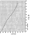
- an exposure time for the pixels such that there is an equal lightness change between steps in gray level halftone design.
- An example of a lightness vs. exposure time curve is shown in Figure 18. This exposure curve is that obtained for continuous tone, which is then normally used for halftone. Such a curve works well also for continuous tone output and gray level error diffusion as well as partial dot halftone.
- these methods have granularity limitations when the toner particles are relatively large (e.g. 12 microns volume diameter).
- the exposure times are associated with different dot sizes. For example, with 3 bits/pixel, there can be 7 different exposure times (or intensity levels if intensity is varied rather than exposure duration), and thus 7 different dot sizes.
- a problem selecting the 7 exposure times from the continuous tone curve can be recognized from Figure 19, which shows lightness of the overall gray level of a halftone vs. a step number of the halftone, for a mixed dot type halftone cell described later. As can be readily seen, there is a non-even lightness jump in some of the steps. If the unevenness of this lightness jump is too great, noticeable density contouring in the output print will occur.
- continuous-tone pictures cap only be printed in binary form through a halftoning process.
- the halftone process breaks the picture into dots via a screen-like structure.
- a sensation of gray shades is achieved.
- increasing the dot resolutions for example, 2000 dots per inch (dpi) - 3000 dpi or higher
- making the dots smaller are the way to produce a high quality picture (a continuous-tone like picture).
- 400 dpi or 500 dpi printing resolutions with 8-bit to 12-bit gray scales are adequate for true continuous tone photographic quality printing.
- Such continuous tone printing systems for example, the photographic film based process and the dye sublimation thermal based process
- These are very expensive exposure system controls which deliver 8-bit to 12-bit gray scales.
- Those printing devices and exposure system controls currently use two designs: a current modulating laser intensity system or a time modulating laser exposure system.
- the toning process is based on the differential electrostatic force generated by the charge potential on the latent image.
- a well (i.e. satisfactorily) formed cluster type of charge-potential-well is therefore advantageous for developing a stable dot.
- Certain dot designs have a well formed potential well already built in, so that the rendered images will be less grainy. However, certain other dot designs will render a grainy image because there is no such well formed charge-potential-well for that dot structure on the latent image to stabilize the dot.
- a method of producing a gray level image comprising controlling a gray level printhead such that the printhead forms dots of variable dot sizes on a recording medium at plural pixel locations, the pixel locations being grouped into cells having cell gray levels, wherein the dots of a cell are determined such that for each increase in cell gray level, a dot at at least one of said pixels in the cell forms a larger dot-size.
- an apparatus for reproducing an original image comprising a scanner which scans and digitizes the original image into pixels ; a controller means coupled to the scanner to receive the digitized original image, and which produces a first signal corresponding to a gray level halftoned representation of the digitized original image; and a printer coupled to the controller to receive said first signal and which produces a gray level halftoned reproduction of the original image wherein the controller means groups the pixels into cells that each have a determined cell gray level, and controls the formation of dots within the pixels of an individual cell by the printer such that for each increase in cell gray level, a dot at at least one of said pixels in the cell forms to a larger dot-size.
- an apparatus for reproducing an original image comprising a scanner which scans the original image and generates first signals representing said original image as pixels of different gray level values; a controller coupled to the scanner and responsive to the first signals, and which generates second signals corresponding to a gray level halftoned representation of the original image; and a printer coupled to the controller to receive said second signals and which produces a gray level halftoned reproduction of the original image; and wherein the controller includes means for defining a criteria for stable pixel locations in accordance with a screen frequency and screen angle of the image to be reproduced and for determining in accordance with said criteria whether or not there is to be a stable dot at a current pixel and if the current pixel is determined to be at a location meeting said criteria for a stable pixel location, alters a gray level value of the current pixel to increase the density of the current pixel for stabilizing said pixel at said location and diffuses error introduced by increasing the density of the current pixel to pixels that neighbor the current
- a method of reproducing an original image comprises the steps of generating first signals representing an original image divided into pixels of varying intensity values; in accordance with a criterion based on screen frequency, identifying a current pixel as being a preferred pixel for forming of a stable dot if the current pixel meets said criterion; in response to a current pixel being identified as a preferred pixel introducing an error to adjust the intensity value of the current pixel to form a modified intensity value; comparing the modified intensity value with a threshold value; and as a result of said comparing step defining a grey level value for printing the current pixel; and distributing the error to adjust intensity values of pixels neighboring a preferred pixel that are not preferred pixels.
- a method of reproducing a original image that contains at least one of a text region or a halftone region comprises scanning said original image to produce a signal representing a digitized original image; determining that a region of said original image contains either a text region or a halftone region; and performing contour suppression on every pixel of said digitized original image; controlling a gray level printer to print the digitized original image after contour suppression has been performed.
- a method of reproducing an original image that contains at least one of a text region or a halftone region comprises scanning said original image to produce a signal representing a digitized original image, said original image having a screen frequency; determining that a region of said original image contains either a text region or a halftone region; and controlling a gray level printer to print the digitized original image with an output screen frequency higher in screen frequency than the screen frequency of the original image.
- a method of reproducing an original image comprises
- a method and apparatus of reproducing an original image comprising scanning an original image to produce a digitized image; performing a local structure analysis of the digitized image; selectively applying a descreening filter to a region of the digitized image based on the results of the local structure analysis to remove a specific frequency of the digitized image caused by halftone screens; bypassing the descreening filter with regions of the digitized image such that bypassed regions remain unfiltered by said descreening filter; printing filtered regions and bypassed regions as a single, unified reproduction of the original image; and wherein in the descreening filter the image is transformed to a frequency spectrum and the strength at a certain frequency is reduced and the modified image transformed into the spatial domain, and there is feedback between the spatial domain and the frequency domain to iteratively reduce to a minimum the certain screen frequency.
- an apparatus for reproducing an original image comprising means for scanning and digitizing the original image into pixels; controller means for producing a first signal corresponding to a gray level halftoned representation of the original image; and a gray level printer means coupled to the controller means and responsive to said first signal for producing at least three gray level dot sizes to form a gray level halftoned reproduction of the original image; wherein the controller means includes first means for processing the pixels by cells, each of plural pixels, and for controlling the printer means to form dots of variable size in a cell along lines in accordance with at least one template, such that a first line structure is formed that is stable before beginning formation of additional lines within the cell corresponding to increasing cell gray levels.
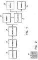
- Figure 1 illustrates an apparatus which reproduces a document in accordance with the various aspects of the invention described herein.
- the document 10 can contain different types of images on the same document.
- document 10 may contain both text and continuous tone areas, and may also contain halftone areas.
- the document 10 is scanned in and digitized by a conventional scanner 12, which operates to provide digital signals representative of the densities of the areas of the document 10 corresponding to various pixels. These signals are sent to a memory (or buffer) 14. Under the direction of a controller 16, these signals may be modified and provided as gray level signals through a frame store 17 to a printer 18 and/or a display 20 for each pixel. The printer 18 and/or display 20 will then reproduce the document 10 by energizing each of the individual pixels according to the gray levels as modified (or not modified) by the controller 16.
- the printer may be a gray level LED printhead or a laser printer or other grey level exposure device.
- the printer may be an electrographic recording device that imagewise charges an electrostatic image supporting member.
- the member may be photographic film or a photoconductive image supporting member.
- the controller 16 of the present invention may include a computer that is programmed or hardwired in accordance with the teachings herein to carry out the various aspects of the invention.
- the controller operates to modify the gray level that is to be printed for a pixel in dependence on the local contrast.
- the controller 16 will select between a "mixed dot" type rendering technique and a "fixed threshold” type rendering technique. Before describing the selection process, these two rendering techniques will now be discussed.
- each pixel has the capability to be rendered in several different dot sizes, and thus different gray levels.
- several pixels may be organized together to form a superpixel, or cell.
- Each of the pixels in a cell is then provided with a gray level.
- the human visual response integrates the various gray levels of the individual pixels in the cell to a single perceived gray level for the cell. This is similar to the basic concept of binary halftoning.
- the number of tone scales for a cell is increased greatly, however, due to the number of different gray levels available for each pixel.
- eight levels can be provided with gray level printing for each pixel in a cell (3 bits/pixel).
- the gray level printing allows 121 different gray shades to be rendered for that cell.
- An example of a 4x4 cell 28 with numbers that represent gray levels for each pixel is shown in Figure 2.
- the formation of the dots in the pixels of a cell can be performed in a number of different manners to achieve different desired results.
- the dots can be formed as "full” dot, "partial” dot, or “mixed” dot to provide gray level halftoning.
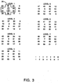
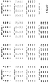
- Figure 3 illustrates an example of a 3-bit gray halftone dot layout for a full dot type cell formation. Also illustrated are seven different pixel-dot sizes, corresponding to the sizes that each individual pixel-dot can obtain. There are 57 possible gray levels for the exemplary eight element cell 30 shown here. An example of the formation of a cell that is at gray level 12 will now be given.
- the pixel circled in level 1, reference numeral 1, is formed to dot-size 1 in level 1. (Only one cell will be described, although the pixels of other cells are changed according to the same layout, as shown in Figure 3).
- the dot at this circled pixel grows larger and larger as the levels increase from level 1 to level 2 all the way to level 7. One can see that this pixel increases in value from 1 to 7 as the levels increase. If the desired gray level for the cell 30 was 7, then the formation of this cell would be completed once the circled pixel 1 has reached the dot-size of 7 in level 7. In this example, however, the gray level for the cell 30 is desired to be 12.
- the circled pixel 1 has reached its maximum dot-size, so that a dot at another pixel within cell 30 must now start forming. This dot starts forming at the pixel indicated with a square around it in level 1, with the numeral 8.
- the dot formation process continues, with the dot at this second pixel growing larger and larger as the levels again increase from level 1 to level 5.
- the formation process stops at level 5, since the pixel has now reached the value of 12.
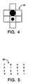
- the halftone cell 30 now contains, as seen in Figure 4, a dot of dot-size 7, and a dot of dot size 5.
- the extension of this formation process to 57 gray levels is easy to see from this example.
- gray level 55 is at Level 6 in Figure 3. All pixel locations in cell 30 that are less than 55 in Level 6 are grown to dot-size 7, whereas the pixel at location 55 is grown to dot size 6.
- the full dot type process thus involves forming dots in a cell at the highest priority pixels to their maximum allowable dot-size before beginning the formation of the dots at the next highest priority pixels.
- An exemplary halftone dot mask 32 with pixel priorities indicated is shown in Figure 5. Different matrix sizes, cell shapes and priorities can be used for the cells than that illustrated in Figure 3, without departing from the spirit and scope of the present invention.
- the full dot type formation process is favored because it forms stable dots and exhibits less granularity (halftone printing noise).
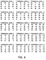
- a 3-bit gray halftone dot layout for the partial dot type formation process is shown in Figure 6.
- the cell 34 is built by providing a dot of the same size to each pixel in the cell to the extent possible, before building up the dot at any particular pixel to the next larger size.
- the circled pixel in level 1 would have a dot formed at that pixel with a dot-size of 1, as would similarly pixel locations "2", "3", "4", "5" and "6".
- each of the pixels in the cell 34 would be built up to at least dot-size of 1.
- the pixels indicated with a square around them in level 2 would be built up to have a dot size of 2.
- the partial dot formation process can thus be seen to spread out the information over the cell, and therefore carries more information detail than the full dot. It does suffer from less stable dots and more granularity, however.
- the mixed dot type combines the merits of both the full dot and the partial dot types in gray level halftoning.
- a number of different processes can be provided to combine the full dot type and the partial dot type, with the specific mixed dot type being chosen based on which renders an image with more smoothness, less graininess, and more image details. Suggested strategies are: 1) build small stable dots in the highlight (toe) region; 2) keep tone response linear in the mid-tone region; 3) reduce dot structure in the shadow (shoulder) region and render more details.
- a specific mixed dot type can be chosen by one of ordinary skill in the art to optimize stable dots, more image detail and less graininess.
- FIG. 7 An example of a specific mixed dot type 3-bit gray halftone dot layout is illustrated in Figure 7.
- the pixels are constrained from growing beyond dot-size of 5.
- the pixels grow in a full dot type process, with the pixel circled growing to a dot-size of 5, with the pixel that is squared then starting to grow in size.
- the cell then increases in gray level by using a partial dot type process. In other words, each of the pixels in the cell must grow to a dot-size of 6 before any of the pixels begins growing to a dot-size of 7.
- FIG 8. An example of a 4-bit gray halftone dot layout for mixed dot type is illustrated in Figure 8. The formation of the dots is the same in concept to that illustrated in Figure 7. Because there are 15 dot sizes available for each pixel, 121 gray levels for an eight element cell are obtainable.
- the highest priority pixel grows to dot-size 11 for corresponding cell gray levels 0 to 11.
- the pixel of the next highest priority is then added and is of dot size 1.
- the corresponding increases are made to the pixel of next highest priority until both said pixels are at gray level 11.
- further growth in cell density occurs by increasing the dot-size or density of the pixel at the third highest priority location and so on.
- cell gray level 88 further increases in cell gray level are made by distributing the increases to the pixels in accordance with the growth pattern described for the partial dot approach.
- Another type of rendering technique is a fixed threshold method.
- each individual pixel is rendered with only limited tone scales. For example, 4 bits/pixel renders 16 different tone shades.
- the fixed threshold type renders the highest resolution among the various types, and an edge can be rendered more accurately down to each pixel.
- the fixed threshold type renders an image with even higher sharpness than the partial dot type since it is not limited by the cell size as is the partial dot type.
- the problem with the fixed threshold type is that it has less tone scale, so that a false contour could easily be seen in the rendered image.
- the fixed threshold type will provide excellent rendering results on text and halftone originals.
- the mixed dot type is the best choice for continuous tone rendering.
- the full dot type creates a screen structure in the background of text and a Moire pattern in the halftone.
- the mixed dot type also creates a screen structure in the background of text and creates a Moire pattern in the halftone, though weaker than that created by the full dot type.
- the fixed threshold type renders well on both text and halftone.
- the unified rendering technique of the present invention uses both fixed threshold type and mixed dot types according to local image content so that text, halftone and continuous tone images are all reproduced well.
- a 4-bit mixed dot type thresholding mask is illustrated in Figure 9, while the fixed threshold type thresholding mask is shown in Figure 10.
- These thresholding masks are derived from a dot layout, such as shown in Figure 8 for the mixed dot type. (The dot layout for the fixed threshold type is not shown, only the derived thresholding mask).
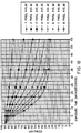
- the thresholding masks are derived from the dot layouts using a tone reproduction control chart, such as shown in Figure 12.
- the tone reproduction chart has four quadrants.
- the first quadrant (I) contains the input and output density of a specific tone reproduction curve, which specifies the gamma or the contrast of the image to be reproduced.
- the second quadrant (II) captures the characteristics of the gray level printing process.
- the fourth quadrant (IV) preserves the characteristics of the scanner, which converts the density to a gray value.
- the third quadrant (III) maps gray values into gray steps linking the quadrants IV, I and II together.
- the step number of the dot sequence in the dot layout of a cell is replaced by a gray value.
- the mapping along arrows a, b, c, and d provides the gray value of 12.
- the gray value maps to 224.
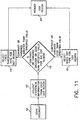
- FIG. 11 An exemplary embodiment of a method for unified image rendering is illustrated in Figure 11.
- a document 10 is scanned in step 40, using the scanner 12 as shown in Figure 1.
- the controller 16 collects statistical information from each dot region (e.g. 4x4 pixels) in step 42.
- This statistical information can include contrast, variance, variation or roughness, for exAlthough any one of the three dot types (full, partial or mixed) coample.
- the contrast is defined as the difference between local maximum intensity and local minimum intensity.
- the variation is defined as the average of the intensity difference between the nearest neighboring pixels. Techniques for finding the contrast or the variation are well known to those of ordinary skill in the art.
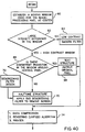
- the present invention determines in step 43 ( Figure 11) whether the contrast or variance of a dot region is greater than a specified value in step 43. If the contrast or variance is greater than the value, a fixed threshold type dot is selected for that dot region (step 44), otherwise, a mixed dot is selected (step 46). Finally, the image is reproduced by the printer 18 in step 48, with the specific dot region rendered in either the selected fixed threshold type or mixed type dot.
- a fixed threshold type dot is rendered for text and halftone, since text and halftone are usually higher contrast in nature. This will not cause the Moire pattern in the halftone and will produce a smooth text boundary.
- the mixed dot the best of the different dot types for continuous tone images, is rendered for the continuous tone region.
- Collecting the statistical information and locally selecting the appropriate dot type from between a fixed threshold type and a mixed dot type provides superior reproduction of an image that contains different types of image regions, such as text, halftone and continuous tone regions.
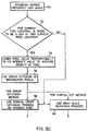
- FIG 13 Another exemplary embodiment of a method for unified image rendering is illustrated in Figure 13. This method is the same as that shown in Figure 11, except that if the contrast or variance is greater than the value, a partial dot is selected for that dot region (step 44), otherwise, a mixed dot is selected (step 46).
- a partial dot is rendered for text and halftone, since text and halftone are usually higher contrast in nature.
- the partial dot type will not cause the Moire pattern in the halftone and will produce a smooth text boundary.
- the mixed dot the best of the different dot types for continuous tone images, is still rendered for the continuous tone region in this embodiment of the present invention.
- Collecting the statistical information and locally selecting the appropriate dot type from between a partial dot type and a mixed dot type provides superior reproduction of an image that contains different types of image regions, such as text, halftone and continuous tone regions.
- the unified rendition method described above achieves many quality goals to render a mixed type document.
- there are some noise problems associated in the halftone printing due to its rendered weak dots in the halftone picture.
- To stabilize the rendered dots in the halftone picture a different screen structure is necessary to impose on the original halftone screen.
- this enhances the Moire pattern in the halftone picture.
- a compromise between the noise issues and the Moire pattern is necessary to minimize the problem in printing halftone pictures and other mixed types of images.
- a method and apparatus for reproducing an original image scans an original image to produce a digitized image, performs a local structure analysis of the digitized image and selectively applies a descreening filter to a region of the digitized image based on the results of the local structure analysis to remove a specific frequency of the digitized image caused by halftone screens.
- the descreening filter bypasses regions of the digitized image such that the bypassed regions remain unfiltered.
- the filtered regions and the bypassed regions are printed as a single, unified reproduction of the original image. This removes halftone screens from the image while maintaining the contrast of the text.
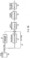
- FIG. 38 The approach of the present invention, a basic flow diagram of which is illustrated in Figure 38, further enhances the quality of the unified rendition method in dealing with a mixed type document.
- a document is scanned in step 40, and this scanned document is processed through a descreening filter in step 42 which removes only a certain frequency caused by the halftone screen.
- the descreening filter can be resident in the scanner 12 or the controller 16 of Figure 1. The text blurring effects of this filter have been minimized for the specific designed filter characteristics.
- a local structure analysis of the image is performed by the controller in step 44.
- the filter operation is applied selectively to the image region based on the results of this local structure analysis.
- the controller will not alter those pixels along the text border (see bypass 43) while it filters those pixels in a low contrast region and in a halftone dot region. In this way, the text contrast is maintained and the noise and the halftone screen are smoothed out.
- the processed image is then stored ( step 46 ) and rendered later through the unified method (step 48) and printed (step 50).
- a frequency spectrum is selected in which the frequency response needs to be achieved. For example, in the present invention, it is desired to boost a certain frequency region while smoothing out another frequency region in the 256x256 size spectrum because of the scanner modulation transfer function which needs to be corrected in this manner.
- This frequency spectrum has a real number representation instead of a conventional complex number (a real part and an imaginary part) representation.
- the filter modifies the frequency strength around some frequency spots of the desired frequency spectrum to a minimum (i.e., approaching zero response) in a continuous but sharp slope change. These frequency spots are the locations of the halftone screen frequency. Other frequencies will not be altered.
- this modified frequency spectrum is then applied to an inverse FFT (Fast Fourier Transform) back to the spatial domain where image processing is operated. It has now a complex number representation in the spatial domain.
- An mxn window near the center (i.e., low frequency response region) of the real part of the spatial spectrum is cropped out.
- This window size is the designed filter size, for example a 5x5 filter kernel size. Due to this window cropping operation, certain regions in the spatial domain were excluded, in other words, coefficients are set to zero outside of the window. This cropping will modify some of the response shape in the desired frequency spectrum. Hence several feedback loops between the second step and the third step of previous described method are performed to enforce the strength of the screen frequency to be removed to the minimum.
- a final m x n window in the spatial domain is then chosen as the kernel of the descreening filter.
- This filter when operated on the image, will then remove the specific frequency generated by the halftone screens. However, this filtering operation will also smooth out some contrast of text (the blurring effects) to a certain extent.
- the filter is convolved with image pixels to produce a result.
- a structure analysis in the current window for example, 5x5 sizes
- the original pixel is output instead of the convolved result if there is a text structure in the operated window.
- some regions with text structures are maintained in the original pixel values while other regions with halftone structures are convolved with a descreening filter.
- the present descreening invention makes a determination that a region is halftone or text, or is low or high contrast. Both text and halftone structure are high contrast, but their local structures are different. For example, text as normally presented has a high contrast transition across its border. One side has a high pixel value while the other side (in vertical direction or in horizontal direction) has a low pixel value. If the pixel value difference from one side to the other side is greater than a certain threshold, it is determined to be a high contrast window. Otherwise, it is determined to be a low contrast window. If there is a consistent transition in the high contrast window such that one side has high values while the other side has low values, it is assumed that a text structure is in this window.
- step 60 a moving window (such as a 5x5 window) is established for the image, with the pixel being processed at the center of this image.
- step 62 it is determined whether there is a large intensity difference in the window. If there is not a large intensity difference, then the windowed region is a low contrast region, so that a smoothing filter operation to remove noise is applied in step 64, and these filtered pixels are provided to step 74 to be stored (compressed), rendered, and printed.
- a simple smooth filter that can be used is a weighted average operated with 3x3 or 5x5 window size.
- the window is determined to be a high contrast window.
- the consistency of the transition within the window around the central pixel is then evaluated in step 66. If there is a consistent transition, then the window is considered to contain text structure and the original pixel is provided as an output in step 68.
- the structure in the window is considered to be halftone structure, and the 5x5 descreening filter is applied to remove the screen in step 70.
- the image is Fourier transformed into the frequency domain and then some specific frequency content (such as 133, 150, or 200 lines per inch or respectively 5.24, 5.91 or 7.87 lines per mm screens) are removed. This modified Fourier image spectrum is then transformed back to the spatial image domain to complete the removal of the halftone screen. After being descreened, the image pixels are provided to step 74 for final processing.
- the design of the descreening filter can be performed "on-line" as indicated by step 72, or it can be already provided. However, this is computationally slow, and it is preferred to operate the filter design off-line and only perform convolution in the halftone window structures on-line.
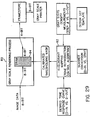
- FIG. 29 A simplified block diagram illustrating the gray scale rendering process is provided in Figure 29 and reference will now be made to elements described in Figure 29.
- Eight-bit image data is input to the digital halftone process block 60, which also receives signals relating to a calibrated thresholding mask that is created.
- the tone reproduction block 62 performs the 40-quadrant mapping illustrated in Figure 12 to create a threshold pattern such as shown in Figure 9 and described below.
- the tone reproduction block receives as inputs the desired tone response curve, the gray steps density measurements, and the scanner converstion and generates a mapping from step number to gray code value output as the calibrated thresholding mask.
- the digital halftoning process block 60 converts the input pixel value into output exposure levels through the thresholding value setting at each pixel location in the cell. This can be implemented by a SRAM 64 lookup table that receives the thresholding mask. An image with a reduced bit-depth of four bits in the output of the digital halftoning process block 60.
- the 4-bit image is provided to a framestore and can then be printed by a 6-bit gray scale printer. (Other information such as 2-bit pixel classification information can be added to the 4-bit image data from the framestore.)
- a 4-bit mixed dot type thresholding mask is illustrated in Figure 9.
- This thresholding mask is derived from a dot layout, such as shown in Figure 8 for the mixed dot type, using the tone reproduction control chart, as shown in Figure 12.
- the tone reproduction chart has four quadrant.
- the first quadrant (I) contains the input and output density of a specific tone reproduction curve, which specifies the gamma or the contrast of the image to be reproduced.
- the second quadrant (II) captures the characteristic of the gray level printing process.
- the fourth quadrant (IV) preserves the characteristics of the scanner, which converts the density to a gray value.
- the third quadrant (III) maps gray values into gray steps linking the quadrants IV, I and II together.
- the step number of the dot sequence in the dot layout of a cell is replaced by a gray value.
- the mapping along arrows a, b, c, and d provides the gray value of 12.
- the gray value maps to 224.
- the values of the step number and the gray values are inversely related). In this manner, the thresholding masks of Figure 9 is derived.
- the thresholding mask is used to determine what the gray level of an output pixel should be given corresponding to its input pixel gray value. Assume, for example, that the input image pixel at location (1,1) of the 4x4 matrix cell of Figure 9 has a gray value of 56.
- the 15 thresholding values at the (1,1) location of the 4x4 cell are: 71, 69, 66, 64, 61, 59, 57, 54, 53, 51, 50, 49, 19, 12 and 9.
- the output gray level 7 is given to that pixel.
- the layouts described above used a 4x4 cell template, and renders a picture with a 45 degree orientation, 141 screen frequency with 121 gray levels.
- the present invention provides a screen layout using a 6x6 cell template which will render a picture with 45 degree, 189 lines per inch (7.44 lines per mm) type screens at 400 dpi (15.74 dots per mm) resolution, and can produce a maximum of 181 gray levels for the 4-bit image, although it will normally render 156 gray levels.
- the increase in the number of gray levels and the higher screen frequency provide the present invention with successful picture rendering results.
- Figure 14 graphically depicts the basic process for constructing the dots.
- the dots according to a set of templates, such as those shown in Figure 15, are built in a line-type structure.
- the selection of how may gray levels are used with the first template is based on the printing process characteristics in which the dots start to form a stable line structure instead of a dust appearance.
- An exemplary embodiment of the present invention uses the gray level of 5 for the initial line build-up, and indicated by template A of Figure 15.
- template A of Figure 15 uses the gray level of 5 for the initial line build-up, and indicated by template A of Figure 15.
- the dots are laid down along lines according to the arrangement of template A.
- the dots are laid down along lines also according to the arrangement of template A, but are all of size 2.
- the template A arrangement for growth is similarly used for growth to successive gray levels up to gray level 5.
- the process continues by building multiple pixel dots at each gray level on top of the line structure so as to produce a more stable line structure that has a smoother shade gradation. This step uses templates B and C to build the dots.
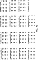
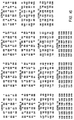
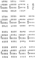
- Figure 16 provides an example of a 189 lines per inch, gray scale dot sequence with indicated level numbers.
- the pixels are arranged in 6x6 blocks.
- the formation of the dots follows the same process as already described with respect to Figures 3, 6, 7 and 8 for different layout designs.
- An example of the exposure levels for the cell at gray level 100 is shown in Figure 17. This exposure level is found in level 8 of Figure 16.
- Those pixels in Figure 17 that have exposure levels of 7 correspond to those pixels in Figure 16, level 8 that are greater than 100, and so have not reached level 8 exposure yet.
- R R p + A D ⁇ f(t) - R P ⁇ , where R P is the reflectance of the paper base, A D is the toned dot area/unit area and f(t) is the reflectance of the toned area as a function of exposure time (t) for a continuous tone patch and R is the reflectance of the halftone patch, then for more than 5 pixels in a cell that are turned on, A D approaches 1 (the continuous tone case). This assumption is true only for a mixed dot of a specified type of 141/inch screen (at 45 degree angle) with a 400 dpi system.
- a D ⁇ 1 and A D increases from 0 to 1 with respect to a function that is related to the perimeter of the dot/unit area.
- the printhead of the printer 18 may be a 6 bits/pixel gray level printhead. This may provide 40 uniformly corrected gray levels per pixel. In the present invention, only 3 bits or 4 bits per pixel are used to identify the gray level image data of the pixel so as to provide a device independent approach in printing. By using the halftone structural information, it is possible to produce a more even lightness jump between steps.
- Figure 20 illustrates a flow chart for converting the device independent 4-bits/pixel image data to 6 bits/pixel gray level exposure time (or intensity) data (see in this regard, WO 91/10311).
- the printer 18 receives 2-bit classification information that identifies which pixel location and line location inside a halftone cell is being addressed. This information is generated by a classifier in step 52 which essentially indicates whether the pixel is in the center of a cell or on the periphery of the cell by the generation of a 2-bit sub-address.
- the 2-bit sub-address containing structural information is combined with the 4-bits of image information to act as an address for a 40 levels/pixel look up table (LUT).
- the printhead pixel location in the line is provided to address which one of the 4992 pixels in a full wide printhead for which the pixel is supposed to extract the 40 levels of information.
- the output from the LUT is 6 bits/pixel printer information that is sent to the printhead in step 56.
- Figure 22 illustrates another embodiment of the method of the present invention.
- the first LUT 55 is a non-uniformity brightness LUT (8K bytes).
- the second LUT 53 is a 14-bit address LUT that provides the correct exposure for each pixel when provided with gray value input and position classifier input.
- the non-uniformity LUT 55 can be an 8K byte SRAM, for example.
- the brightness of the LED elements is sorted into 256 "bins" so that a better usage of the non-uniformity range of an LED is used.
- the pixel counter points to each individual element which then outputs its brightness bin (1 of 256).
- This eight-bit brightness bin acts as an index pointer to the 14-bit LUT 53, which can be a 14-bit x 8 SRAM ⁇ 16K bytes LUT.
- the 14-bit LUT 53 has the rest of the LUT address (6 bits) from the 4-bit gray levels input and the 2-bit position classifier. Although there are theoretically 64 levels for each pixel, due to the nonuniformity of the printhead, there are only approximately 40 real levels that exist after non-uniformity correction for some elements.
- FIG 21 An example of a classifier is shown in Figure 21, which illustrates a 4x4 classifier 60.
- the first class is a pixel within the center of a cell (1).
- the second class are those pixels which surround the center pixel (2).
- the third class are those pixels which may overlap pixels in the surrounding halftone dots (3).
- the 2-bit sub-address provides information sufficient for three classifications.
- Class 3 pixels are essentially very much like continuous tone, so that one can use the exposure times for the continuous tone curve for exposure (the 8 pixels curve) that was illustrated in Figure 18.
- the exposure times for the continuous tone curve for exposure the 8 pixels curve
- These exposure values are stored in the LUT, so that once the pixel location in a halftone cell is classified by the classifier, a different exposure level is provided by the LUT to achieve a more even halftone lightness jump.
- the exposure level may be (a). If the pixel next to the first one is class 2, and would have an exposure level of (a) if standing alone, this second pixel of class 2 will be assigned an exposure level of (b), which will be lower than (a), to achieve an equivalent change in lightness in the halftone.
- this second pixel of class 2 will be assigned an exposure level of (b), which will be lower than (a), to achieve an equivalent change in lightness in the halftone.
- the approach of still another embodiment of the present invention has reduced the bit-depth from 8-bits to 4-bits, so that a compression or data packing is achieved.
- This rendition goal is not the same as that of data compression.
- data compression it is mainly for storage/transmission purposes which later expand the compressed image to the original image form without visual loss of information.
- the result of data packing in the multi-bit rendering of the present invention benefits the throughput of the system and the bandwidth of the data transfer.
- the present invention extends the dispersion dot type which is often used in binary halftone rendering to a multi-bit dot pattern.
- the gray scale dot designs "full”, “partial”, and “mixed” dot types have been defined above.
- Each dot type has its own tonal characteristics and texture patterns.
- dot template i.e., the optimal Bayer dot pattern or the cluster dot pattern
- pixel bit-depth i.e., 4-bit or 5-bit per pixel
- the "partial" dot type structure a set of gray dot patterns is generated that will create a continuous tone look image.
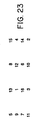
- a Bayer dispersion dot template is illustrated in Figure 23, and the 4-bit partial dot pattern set gray dot pattern in Figure 24.
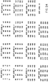
- the thresholding pattern for gray scale rendering obtained from the patterns of Figure 24 by the 4-quadrant tone reproduction process are illustrated in Figure 25.
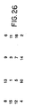
- a cluster dot pattern dot template is illustrated in Figure 26, and the 4-bit partial dot pattern set gray dot pattern in Figure 27.
- the thresholding pattern for gray scale rendering obtained from the patterns of Figure 27 by the 4-quadrant tone reproduction process are illustrated in Figure 28.
- the generation of the threshold mask patterns of Figures 25 and 28 will be described. These thresholding masks are derived from the dot layouts, such as shown in Figures 24 and 27, respectively, using a tone reproduction control chart, such as shown in Figure 12.
- the tone reproduction chart has four quadrants.
- the first quadrant (I) contains the input and output density of a specific tone reproduction curve, which specifies the gamma or the contrast of the image to be reproduced.
- the second quadrants (II) captures the characteristic of the gray level printing process.
- the fourth quadrant (IV) preserves the characteristics of the scanner, which converts the density to a gray value.
- the third quadrant (III) maps gray values into gray steps linking the quadrants IV, I and II together.
- the step number of the dot sequence in the dot layout of a cell is replaced by a gray value.
- the mapping along arrows a, b, c, and d provides, in this example, the gray value of 145 (not shown in Figure 12 but see Figure 25, level 7).
- the gray value maps to 250 (not shown in Figure 12 but see Figure 25, level 1).
- the values of the step number and the gray values are inversely related). In this manner, the thresholding masks of Figures 25 and 28 are derived.
- the thresholding mask is used to determine what the gray level of an output pixel should be given corresponding to its input pixel gray value. Assume, for example, that the input image pixel at location (1,1) of the 4x4 matrix cell of Figure 25 has a gray value of 125.
- the 15 thresholding values at the (1,1) location of the 4x4 cell are: 250, 234, 218, 202, 186, 170, 154, 138, 122, 106, 90, 74, 58, 42 and 26.
- the output gray level 8 is given to that pixel.
- a digital halftoning process converts the image into a multi-bit image representation with the thresholding values of either Figure 25 or Figure 28, depending on which dot template is used.
- This multi-bit image has a continuous-tone look structure with a weak dot screen imbedded in it.
- a continuous-tone look image is then reconstructed from the multi-bit rendered image through a gray scale printer.
- the constructed images have no visual screen structure. Hence, a continuous tone picture printing is achieved through the multi-bit image rendition method.
- FIG. 29 A simplified block diagram illustrating the gray scale rendering process of the present invention is provided in Figure 29.
- Eight-bit image data is input to the digital halftone process block 60, which also receives signals relating to the calibrated thresholding mask that has been created as in Figures 25 and 28.
- the tone reproduction block 62 performs the 4-quadrant mapping illustrated in Figure 12 to produce threshold masks from the dot layouts.
- the tone reproduction block receives as inputs the desired tone response curve, the gray steps density measurements, and the scanner conversion, and generates a mapping from step number of a dot layout to a gray code value output of the calibrated thresholding mask.
- the digital halftoning process block 60 converts the pixel value into output exposure levels through the thresholding value setting at each pixel location in the cell. This can be implemented by a SRAM 64 lookup table that receives the thresholding mask. An image with a reduced bit-depth of four bits is the output of the digital halftoning process block 60.
- This 4-bit image is provided to a framestore and can then be printed by a 6-bit gray scale printer. (Other information such as 2-bit pixel classification information, can be added to the 4-bit image data from the framestore).
- an image that looks like a continuous tone picture is provided using a reduced (4-bits) image representation and gray scale printing.
- the electrophotographic printing process involves: electrostatically charging, exposure, developing (or toning), transfer to a receiver sheet such as paper or plastic, and image fixing stages. Due to its unique toning process which is based on the differential electrostatic force generated by the charge potential on the latent image, a well (i.e, satisfactorily) formed cluster type of charge-potential-well is advantageous for developing a stable dot. Such a well (i.e., satisfactorily) formed potential-well is already built in to the mixed-dot and the full dot types of dot designs described above. Hence, the rendered images are visually less grainy. However, it is not true as an image rendered through the partial dot structure. The image looks grainy.
- an imbedded controlled dot structure in error diffused gray scale image or partial dot rendered image will stabilize the dot.
- the imbedded structure can be in either dot form or line form. The rendered images are more pleasing with the controlled structures added in.
- an error diffusion algorithm for example, to illustrate one method of imbedding dot structure in gray scale images during the rendering process.
- a number of known different error diffusion algorithms could be used in the present invention, such as shown in "An Adaptive Algorithm for Spatial Gray Scale", by Flord and Steinberg, Proc. SID, Vol. 17/2, pp. 75-77 and “Digital Halftoning" by Ulichney. Accordingly, the specifics of an error diffusion algorithm will not be further described here.
- the screen frequency and the angle are determined in order to decide what are the imbedded dot structures; i.e. which dots are the dots which will be stabilized.
- This can be as simple as a periodic screen structure in dot or line form.
- the structure could be, for example, 45 degree lines with 141 lines-per-inch screens at 400 dpi resoluition.
- this dot is determined to be a dot that is to be stabilized.
- Such a determination of pixels that will be stabilized is easy to perform in pixel processing.
- the imposed screen structure can be selected by a designer, but should not be distracting when viewing. Therefore, the periodicity or a template can be determined that is similar to the dot design procedure of a normal halftoning method.
- step (52) it is determined for a corresponding location on the template of a current pixel whether a controlled dot should be laid down or not. If a controlled dot should be layed down, the current pixel value will be lowered proportionally according to its intensity value. Otherwise, it will proceed normally as error diffusion does by jumping to step 58 and use the normal error diffusion process on the current pixel. With the partial dot method (as shown in dashed lines), if a controlled dot should not be laid down, step 60 is performed so that gray scale rendering process such as that shown in Figure 29 is used on the current pixel.
- the purpose of the adjustment on those specific locations is that on this current pixel, more light will be exposed (i.e., the pixel-dot will be slightly darker in the Neg/Pos electrophotographic process) than its original. This current pixel then will act as a stabilized center for the neighboring rendered pixels.
- the amount of adjustment on each pixel could be determined experimentally from the process latitude (i.e., it may be adjusted in two or few more exposure steps on those specific locations according to the process). The amount of the adjustment is dependent on the process conditions such as the toner size, developing potential, photoconductor characteristics, etc. Since the main factor in the toning and transfer process is the electrostatic force mechanism, a larger potential difference created between the pixels is advantageous to stabilize the developing dot and provide an easier transfer.
- the difference of the exposure level may vary with respect to exposures so that a larger difference of exposure is set at lower exposures. For example, if the mean exposure is at level 3 or 4, the controlled pixels should be adjusted to exposure level 9 or 10. However, when the mean exposure is at level 9 or 10 the controlled pixels should be adjusted only to exposure level 11 or 12.
- step 54 the further introduced error on that specific (the current) pixel will then be distributed to its neighborhood pixels to balance the specific pixel. Since this adjustment will not change the total tone value but redistributes it as the error diffusion does, the imbedded dot structure is carried naturally in the gray scale error diffusion image. This added dot structure provides a stabilized center on the latent image and improves the toning development process in the electrophotographic printing.
- this imbedded controlled dot structure can be utilized to the partial dot structure described earlier or other dot structures without a stable dot center in the image.
- FIG. 31 An example of a 6x6 cell subjected to gray scale error diffusion according to the present invention is illustrated in Figure 31.
- the shaded pixels, with higher exposure levels, are the controlled pixels that are to be stabilized.
- the 6x6 cell shown on the left without stabilization there are no large exposure differences among the pixels.
- the exposure at each pixel is scattered among levels 8, 9 and 10, so that there is no well formed structure in the cell.
- the cell on the right of Figure 31 after dot stabilization provides a stable dot structure for developing the flat field, and appears as a screen imposed on top of the 6x6 cell.
- a method and an apparatus for reproducing an original image that has one or more different image type regions.
- a controller operates a gray level printer in a default mode when the original image contains a text region or a halftone region.
- This default mode includes either contour suppression applied to every pixel of the original image or uses an output screen that is a higher frequency than the frequency of a screen of the original image.
- successful gray level halftones at 141/inch screen (45 degree) of the mixed dot type may be produced to represent output images with a gray level printing system at 400 dpi output resolution.
- the gray level halftone is tuned to balance between the visibility of the fundamental screen and the granularity of the system for a particular process.
- 12 microns toner with electrostatic transfer is used.
- a power spectrum of an output print of a 0.8 black density patch with full dot type is shown in Figure 32. As one can see, the fundamental frequency at 141/inch screen is very prominent but the granularity is low.
- the output images using the mixed dot type with a 141/inch screen exhibit a fine balance between sharpness, granularity and screen texture.
- the input to the scanner is a halftone (in this case a 150/inch screen picture)
- this output screen which is good for continuous tone pictorial input
- the 141/inch may break up the fine structures and may not be desirable.
- This aspect of the present invention provides two different methods for providing a default mode that produces satisfactory images for each of the different image types. The first of these is termed “contour suppression/pixel” and the second is termed “higher screen frequency”.
- contour suppression/pixel method of providing a default mode is shown in Figure 35.
- contour suppression is applied to every input pixel. For example, assume that there are 16 gray levels (4 bits) within one pixel and the input data value is just at gray level 3. Then gray level 3 will have a 50% probability to be on, but gray levels 4 to 16 will have a 100% probability to be on and gray levels 1 and 2 will have a 0% probability to be on.
- a halftone input 150/inch screen
- the original halftone is in fact stabilizing tone reproduction with this per pixel contour suppression method.
- the contour suppression/pixel method will be further explained with an example below.
- the generation of a threshold mask has been described with regard to the 4-bit mixed dot type thresholding mask illustrated in Figure 9.
- This thresholding mask is derived from a dot layout, such as shown in Figure 8 for the mixed dot type, using a tone reproduction control chart, such as shown in Figure 12.
- the input image pixel at location (1,1) of the 4x4 matrix cell of Figure 9 has a gray value of 56.
- the 15 thresholding values at the (1,1) location of the 4x4 cell are: 71, 69, 66, 64, 61, 59, 57, 54, 51, 50, 49, 19, 12, and 9.
- the output gray level 7 would be given to that pixel in the method previously described. Hence, that input image pixel with value 56 at location (1,1) will have a probability of gray level 7 being on of 100%. Similarly, the same output gray level 7 would also be given to an image input pixel with a gray value of 55 using the method previously described.
- contour suppression does not involve assigning 100% probability to all pixel values in between the thresholds. Instead, the probability is made proportional to the difference of the pixel value relative to the thresholds. For example, the value 56 will not have gray output level 7 all of the time. If the probability is set to 80%, then this pixel will be output with gray level 7 80% of the time, and with gray level 8 20% of the time.
- This method of contour suppression which does not fix the probability of a specific gray level being on at 100% for values between thresholds, but rather makes it a function of the difference of the pixel value relative to the thresholds, delivers more accurate tone and eliminates false contouring due to large differences between threshold values.
- the contour suppression/pixel method used on scanned in text also shows high resolution. Therefore the system should be able to preserve images whether it is a halftone input or high resolution text/graphics input and has been going through the copying process more than once (recopying). However, if the method is used on continuous tone input, the output can be grainy. In this case, the contour suppression scheme does reduce density contouring compared with a straight threshold value matrix in gray level printing. Further improvement includes passing the original image through an 8 bits to 4 bits conversion type of Bayer matrix to give the system more gray levels, thereby eliminating contour suppression.
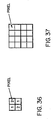
- the second method of the present invention uses a higher output screen such as a 282/inch or 11.10/mm (45 degree screen) shown in Figure 36 or a 200/inch or 7.87/mm (90 degree screen) shown in Figure 37 with gray level printing.
- a moire pattern generated due to the frequency beating of the input and output screens will go to a higher frequency.
- the moire pattern thus generated will therefore be less observable than the moire created by two frequencies that are close to each other, like 141/inch and 150/inch screens.
- the moire pattern from a halftone input image can be further reduced if the strength of the output screen is lessened (e.g., by a partial dot as in Figure 33 or a mixed dot as in Figure 34).
- a balance is made between reducing the moire and the granularity that is generated from a continuous tone image with a certain toner size.
- the granularity for these higher screen systems with continuous tone input would still be better than that of just contour suppression on each pixel since a weak screen is provided to stabilize the system.
- Contour suppression on the halftone may still be necessary for a high screen in order to generate enough gray levels to reduce contouring. Text screening at 282/inch screen has also been shown to be quite satisfactory.
- the above two methods provide a default mode for universal color document digital copying in addition to a photographic mode which can produce very good output with photographic input.
- the default mode will preserve text/graphics, halftone with the least moire and reasonable photographic pictorial inputs.
- the default mode can reproduce photographic input reasonably well, it is preferred that this default mode be supplemented by a photographic mode which deals with continuous tone input very well.
- the invention may be summarized as follows:
Abstract
Description
71, 69, 66, 64, 61, 59, 57, 54, 53, 51, 50, 49, 19, 12 and 9.
250, 234, 218, 202, 186, 170, 154, 138, 122, 106, 90, 74, 58, 42 and 26.
71, 69, 66, 64, 61, 59, 57, 54, 51, 50, 49, 19, 12, and 9.
wherein the controller includes means for defining a criteria for stable pixel locations in accordance with a screen frequency and screen angle of the image to be reproduced and for determining in accordance with said criteria whether or not there is to be a stable dot at a current pixel and if the current pixel is determined to be at a location meeting said criteria for a stable pixel location, alters a gray level value of the current pixel to increase the density of the current pixel for stabilizing said pixel at said location and diffuses error introduced by increasing the density of the current pixel to pixels that neighbor the current pixel.
wherein the step of performing the local structure analysis includes the steps of:
wherein the descreening filter includes means for transforming the digitized image into a frequency domain, means for reducing the strength at a specific frequency content from the digitized image, and means for transforming the digitized image back into the spatial image domain and feedback means between the spatial domain and the frequency domain to iteratively reduce to a minimum the specific frequency in the digitized image.
wherein in the descreening filter the image is transformed to a frequency spectrum and the strength at a certain frequency is reduced and the modified image transformed into the spatial domain, and there is feedback between the spatial domain and the frequency domain to iteratively reduce to a minimum the certain screen frequency.
wherein the controller means groups the pixels into cells that each have a determined cell gray level, and controls the formation of dots within the pixels of an individual cell by the printer such that for each increase in cell gray level, a dot at at least one of said pixels in the cell forms to a larger dot-size.
to a gray level halftoned representation of the original image; and
wherein the controller means includes first means for processing the pixels by cells, each of plural pixels, and for controlling the printer means to form dots of variable size in a cell along lines in accordance with at least one template, such that a first line structure is formed that is stable before beginning formation of additional lines within the cell corresponding to increasing cell gray levels.
wherein the controller means includes means for operating the printer in a first mode when the original image contains a text region or a halftone region, said first mode including contour suppression applied to every pixel of said original image.
Claims (11)
- A method of producing a halftoned gray level image, comprising:controlling a gray level printer such that the printer forms dots of variable dot sizes on a recording medium at plural pixel locations, the pixel locations being grouped into cells having cell gray levels and each cell comprised of plural pixel locations,
wherein a characteristic of the dots of a cell are determined such that for an increase in cell gray level, a dot at at least one of said pixel locations in the cell forms a larger dot-size and characterized in that the gray level printer is controlled to form dots,each of at least three possible gray level dot sizes,along a line type structure in accordance with at least a first predetermined growth pattern for increasing cell gray levels until the line type structure in the cell is stable and is further controlled to form dots, each of at least three gray level dot sizes, along a line type structure in the cell in accordance with at least a second predetermined growth pattern for establishing further increasing gray levels of the cell. - The method of claim 1 and including:processing pixels to be formed as dots by cells, each of plural pixels, wherein in accordance with at least one template, a halftone cell of one gray level is defined as having a first line structure that is stable before beginning formation of an additional line within a cell corresponding to an increased cell gray level.
- The method of any of Claims 1 or 2 and including controlling the processing of the pixels with at least two templates, with pixels being assigned along a line defined by one of said two templates corresponding to increasing cell gray levels until said first line structure is stable, and then assigning pixels along another line determined by the other of said two templates corresponding to increasing cell gray levels.
- The method of Claims 2 or 3 and wherein in accordance with the one template, dot sizes are increased simultaneously at plural pixel locations along the first line structure in the cell when the cell gray level is increased from one gray level to a second and next succeeding gray level.
- The method of Claim 4 and wherein in accordance with the one template, the plural pixel locations are contiguous.
- The method of Claim 4 and wherein in accordance with the one template, all pixel locations along the first line grow simultaneously from the one cell gray level to the next succeeding gray level.
- The method of Claim 6 and wherein in accordance with the first template, pixel locations along plural parallel first lines in the cell grow simultaneously from the one cell gray level to the next succeeding cell gray level.
- An apparatus for reproducing an image, comprising:controller means (16) for producing a signal corresponding to a gray level halftoned representation of the image; anda gray level printer means (18, 20) coupled to the controller means and responsive to said signal for producing pixels in at least three gray level dot sizes to form a gray level halftoned reproduction of the original image;wherein the controller means includes first means for processing the pixels by cells, each of plural pixels, and for controlling the printer means to form dots of variable size in a cell along lines in accordance with at least one predetermined growth pattern, such that a line structure is formed that is stable before beginning formation of additional lines within the cell corresponding to increasing cell gray levels.
- The apparatus of Claim 8 wherein the controller means controls the printer means to form dots in accordance with at least two templates, with dots being formed along lines defined by a first of said two templates corresponding to increasing cell gray levels until said first line structure is stable, and then forming dots along lines defined by the other of said two templates corresponding to increasing cell gray levels.
- An apparatus for reproducing an original image, comprising:means for generating first signals representing an image as pixels of different gray level values;a controller responsive to the first signals, and which generates second signals corresponding to a gray level halftoned representation of the original image; anda printer coupled to the controller to receive said second signals and which produces a gray level halftoned reproduction of the image; andwherein the controller includes means for defining a criteria for stable pixel locations in accordance with a screen frequency of the image to be reproduced and for determining in accordance with said criteria whether or not there is to be a stable dot at a current pixel and if the current pixel is determined to be at a location meeting said criteria for a stable dot location, alters a gray level value of the current pixel to increase the density of the current pixel for stabilizing said dot at said location and diffuses error introduced by increasing the density of the current pixel to pixels that neighbor the current pixel.
- A method of reproducing an original image comprising the steps of:generating first signals representing an image divided into pixels of varying intensity values;in accordance with a criterion based on screen frequency, identifying a current pixel as being a preferred pixel for forming of a stable dot if the current pixel meets said criterion;in response to a current pixel being identified as a preferred pixel introducing an error to adjust the intensity value of the current pixel to form a modified intensity value;comparing the modified intensity value with a threshold value; andas a result of said comparing step defining a grey level value for printing the current pixel; anddistributing the error to adjust intensity values of pixels neighboring a preferred pixel that are not preferred pixels.
Applications Claiming Priority (18)
| Application Number | Priority Date | Filing Date | Title |
|---|---|---|---|
| US07/895,985 US5204753A (en) | 1992-06-05 | 1992-06-05 | Multi-bit rendering method and arrangement for continuous tone picture representation and printing |
| US07/894,858 US5359431A (en) | 1992-06-05 | 1992-06-05 | Classification to change exposure within a cell of different pixels |
| US07/894,857 US5258849A (en) | 1992-06-05 | 1992-06-05 | Halftone dot arrangement in gray level halftone printing |
| US895554 | 1992-06-05 | ||
| US894858 | 1992-06-05 | ||
| US07/894,859 US5313309A (en) | 1992-06-05 | 1992-06-05 | Method and apparatus for printing halftones with a gray level printer with contour suppression and/or minimization of moire patterns |
| US895555 | 1992-06-05 | ||
| US07/895,986 US5239390A (en) | 1992-06-05 | 1992-06-05 | Image processing method to remove halftone screens |
| US07/895,988 US5258850A (en) | 1992-06-05 | 1992-06-05 | Line screen design for gray scale rendering |
| US07/895,555 US5200831A (en) | 1992-06-05 | 1992-06-05 | Method and arrangement for locally switching gray dot types to reproduce an image with gray level printing |
| US895986 | 1992-06-05 | ||
| US07/895,554 US5260807A (en) | 1992-06-05 | 1992-06-05 | Method and apparatus for imbedding controlled structure for gray scale rendering |
| US894857 | 1992-06-05 | ||
| US895988 | 1992-06-05 | ||
| EP93914235A EP0598104B1 (en) | 1992-06-05 | 1993-06-03 | Method and apparatus for reproducing an image with gray level printing |
| PCT/US1993/005097 WO1993026116A2 (en) | 1992-06-05 | 1993-06-03 | Method and apparatus for reproducing an image with gray level printing |
| US894859 | 2001-06-27 | ||
| US895985 | 2001-06-28 |
Related Parent Applications (1)
| Application Number | Title | Priority Date | Filing Date |
|---|---|---|---|
| EP93914235A Division EP0598104B1 (en) | 1992-06-05 | 1993-06-03 | Method and apparatus for reproducing an image with gray level printing |
Publications (3)
| Publication Number | Publication Date |
|---|---|
| EP0892549A2 true EP0892549A2 (en) | 1999-01-20 |
| EP0892549A3 EP0892549A3 (en) | 1999-02-03 |
| EP0892549B1 EP0892549B1 (en) | 2001-11-21 |
Family
ID=27575536
Family Applications (2)
| Application Number | Title | Priority Date | Filing Date |
|---|---|---|---|
| EP98118918A Expired - Lifetime EP0892549B1 (en) | 1992-06-05 | 1993-06-03 | Method and apparatus for reproducing an image with gray level printing |
| EP93914235A Expired - Lifetime EP0598104B1 (en) | 1992-06-05 | 1993-06-03 | Method and apparatus for reproducing an image with gray level printing |
Family Applications After (1)
| Application Number | Title | Priority Date | Filing Date |
|---|---|---|---|
| EP93914235A Expired - Lifetime EP0598104B1 (en) | 1992-06-05 | 1993-06-03 | Method and apparatus for reproducing an image with gray level printing |
Country Status (4)
| Country | Link |
|---|---|
| EP (2) | EP0892549B1 (en) |
| JP (1) | JP3597529B2 (en) |
| DE (2) | DE69331476T2 (en) |
| WO (1) | WO1993026116A2 (en) |
Cited By (7)
| Publication number | Priority date | Publication date | Assignee | Title |
|---|---|---|---|---|
| US6501565B1 (en) | 1998-07-07 | 2002-12-31 | Electronics For Imaging, Inc. | Method and apparatus for smoothing text outlines |
| US6567186B1 (en) * | 1998-10-27 | 2003-05-20 | Hewlett-Packard Company | Method for determining gray values in a printer |
| WO2005112430A1 (en) * | 2004-04-30 | 2005-11-24 | Eastman Kodak Company | Multi-color printing using a halftone screen |
| EP2018040A1 (en) * | 2007-07-19 | 2009-01-21 | Hewlett-Packard Development Company, L.P. | Contouring reduction in halftoning |
| US7508549B2 (en) * | 2004-04-30 | 2009-03-24 | Eastman Kodak Company | Method and apparatus for multi-color printing using hybrid dot-line halftone composite screens |
| US8493623B2 (en) | 2008-10-17 | 2013-07-23 | Eastman Kodak Company | Adaptive exposure printing and printing system |
| US8824907B2 (en) | 2011-04-21 | 2014-09-02 | Eatsman Kodak Company | Electrophotographic printing with column-dependent tonescale adjustment |
Families Citing this family (20)
| Publication number | Priority date | Publication date | Assignee | Title |
|---|---|---|---|---|
| DE69527675T2 (en) * | 1994-04-27 | 2003-04-03 | Agfa Gevaert Nv | Multi-level halftone screening with grouped dots and lines for electrographic color printing |
| EP0682438B1 (en) * | 1994-05-11 | 2000-05-31 | Agfa-Gevaert N.V. | Multilevel halftoning using a randomised Bayer matrix |
| US6317220B1 (en) * | 1996-12-06 | 2001-11-13 | Seiko Epson Corporation | Image forming apparatus capable of preventing linear nonuniformity and improving image quality |
| US6222643B1 (en) * | 1998-11-16 | 2001-04-24 | Conexant Systems, Inc. | Probability error diffusion for digital image printing |
| DE10022225B4 (en) | 2000-05-08 | 2015-12-17 | Heidelberger Druckmaschinen Ag | Multi-level screening with grids of any screen width and screen angle |
| US7079287B1 (en) * | 2000-08-01 | 2006-07-18 | Eastman Kodak Company | Edge enhancement of gray level images |
| US6982814B1 (en) * | 2000-08-23 | 2006-01-03 | Hewlett-Packard Development Company, L.P. | Image printing devices with AM/FM half-toning with self-determination of dot size and method of implementing same |
| US6778299B2 (en) * | 2001-03-09 | 2004-08-17 | Hewlett-Packard Development Company, L.P. | Error diffusion with partial dots method and system |
| US20110235060A1 (en) | 2010-03-29 | 2011-09-29 | Hwai-Tzuu Tai | Screened hardcopy reproduction apparatus compensation data calculation |
| US8482802B2 (en) | 2010-03-29 | 2013-07-09 | Eastman Kodak Company | Screened hardcopy reproduction apparatus with compensation |
| KR20220001519A (en) | 2012-12-27 | 2022-01-05 | 카티바, 인크. | Techniques for print ink volume control to deposit fluids within precise tolerances |
| US9700908B2 (en) | 2012-12-27 | 2017-07-11 | Kateeva, Inc. | Techniques for arrayed printing of a permanent layer with improved speed and accuracy |
| US11141752B2 (en) | 2012-12-27 | 2021-10-12 | Kateeva, Inc. | Techniques for arrayed printing of a permanent layer with improved speed and accuracy |
| US9352561B2 (en) | 2012-12-27 | 2016-05-31 | Kateeva, Inc. | Techniques for print ink droplet measurement and control to deposit fluids within precise tolerances |
| US11673155B2 (en) | 2012-12-27 | 2023-06-13 | Kateeva, Inc. | Techniques for arrayed printing of a permanent layer with improved speed and accuracy |
| JP6102281B2 (en) * | 2013-01-28 | 2017-03-29 | 株式会社リコー | Electrophotographic image output device |
| KR102034420B1 (en) | 2013-12-12 | 2019-11-08 | 카티바, 인크. | Ink-based layer fabrication using halftoning to control thickness |
| KR20230014885A (en) * | 2014-06-30 | 2023-01-30 | 카티바, 인크. | Techniques for arrayed printing of a permanent layer with improved speed and accuracy |
| WO2023177387A1 (en) * | 2022-03-14 | 2023-09-21 | Hewlett-Packard Development Company, L.P. | Selecting print agent dot sizes |
| CN114817615B (en) * | 2022-06-27 | 2022-10-21 | 广州盛祺信息科技股份有限公司 | Accounting original document fast scanning and cloud management system |
Citations (7)
| Publication number | Priority date | Publication date | Assignee | Title |
|---|---|---|---|---|
| US4412226A (en) * | 1981-02-06 | 1983-10-25 | Fuji Photo Film Co., Ltd. | Ink-jet printing method |
| US4651287A (en) * | 1984-06-14 | 1987-03-17 | Tsao Sherman H | Digital image processing algorithm for output devices with discrete halftone gray scale capability |
| EP0291300A2 (en) * | 1987-05-11 | 1988-11-17 | The Mead Corporation | Apparatus for producing an image |
| US4814886A (en) * | 1985-03-20 | 1989-03-21 | Canon Kabushiki Kaisha | Image processing process and apparatus therefor |
| EP0370271A2 (en) * | 1988-11-24 | 1990-05-30 | Dainippon Screen Mfg. Co., Ltd. | Method of and apparatus for recording halftone images and halftone images produced thereby |
| EP0398763A2 (en) * | 1989-05-19 | 1990-11-22 | Canon Kabushiki Kaisha | Image forming apparatus |
| EP0417806A2 (en) * | 1989-09-14 | 1991-03-20 | Dainippon Screen Mfg. Co., Ltd. | Method of recording halftone dot image |
Family Cites Families (8)
| Publication number | Priority date | Publication date | Assignee | Title |
|---|---|---|---|---|
| JPS5537092A (en) * | 1978-09-05 | 1980-03-14 | Ibm | Mode switch for setting threshold value |
| JPS56152373A (en) * | 1980-04-24 | 1981-11-25 | Fuji Photo Film Co Ltd | Laser recording device |
| FR2497043B1 (en) * | 1980-12-19 | 1985-09-13 | Cit Alcatel | IMAGE PRINTING DEVICE |
| GB2121658A (en) * | 1982-05-28 | 1983-12-21 | Linotype Paul Ltd | Mapping ram for a modulated display |
| EP0248616A3 (en) * | 1986-06-02 | 1990-03-07 | Kabushiki Kaisha Toshiba | Picture printing apparatus |
| EP0292292B1 (en) * | 1987-05-20 | 1993-10-06 | Canon Kabushiki Kaisha | Image processing apparatus |
| EP0304289A3 (en) * | 1987-08-18 | 1991-03-13 | Kabushiki Kaisha Toshiba | Half-tone image reproduction method and apparatus |
| DE4025793A1 (en) * | 1990-08-13 | 1992-02-20 | Siemens Ag | METHOD FOR PRINTING A HALFTONE IMAGE |
-
1993
- 1993-06-03 WO PCT/US1993/005097 patent/WO1993026116A2/en active IP Right Grant
- 1993-06-03 EP EP98118918A patent/EP0892549B1/en not_active Expired - Lifetime
- 1993-06-03 DE DE1993631476 patent/DE69331476T2/en not_active Expired - Lifetime
- 1993-06-03 JP JP50152094A patent/JP3597529B2/en not_active Expired - Lifetime
- 1993-06-03 EP EP93914235A patent/EP0598104B1/en not_active Expired - Lifetime
- 1993-06-03 DE DE69324653T patent/DE69324653T2/en not_active Expired - Lifetime
Patent Citations (7)
| Publication number | Priority date | Publication date | Assignee | Title |
|---|---|---|---|---|
| US4412226A (en) * | 1981-02-06 | 1983-10-25 | Fuji Photo Film Co., Ltd. | Ink-jet printing method |
| US4651287A (en) * | 1984-06-14 | 1987-03-17 | Tsao Sherman H | Digital image processing algorithm for output devices with discrete halftone gray scale capability |
| US4814886A (en) * | 1985-03-20 | 1989-03-21 | Canon Kabushiki Kaisha | Image processing process and apparatus therefor |
| EP0291300A2 (en) * | 1987-05-11 | 1988-11-17 | The Mead Corporation | Apparatus for producing an image |
| EP0370271A2 (en) * | 1988-11-24 | 1990-05-30 | Dainippon Screen Mfg. Co., Ltd. | Method of and apparatus for recording halftone images and halftone images produced thereby |
| EP0398763A2 (en) * | 1989-05-19 | 1990-11-22 | Canon Kabushiki Kaisha | Image forming apparatus |
| EP0417806A2 (en) * | 1989-09-14 | 1991-03-20 | Dainippon Screen Mfg. Co., Ltd. | Method of recording halftone dot image |
Cited By (10)
| Publication number | Priority date | Publication date | Assignee | Title |
|---|---|---|---|---|
| US6501565B1 (en) | 1998-07-07 | 2002-12-31 | Electronics For Imaging, Inc. | Method and apparatus for smoothing text outlines |
| US6885477B2 (en) | 1998-07-07 | 2005-04-26 | Electronics For Imaging, Inc. | Methods and apparatus for smoothing text outlines |
| US7636180B2 (en) | 1998-07-07 | 2009-12-22 | Electronics For Imaging, Inc. | Methods and apparatus for smoothing text outlines |
| US6567186B1 (en) * | 1998-10-27 | 2003-05-20 | Hewlett-Packard Company | Method for determining gray values in a printer |
| WO2005112430A1 (en) * | 2004-04-30 | 2005-11-24 | Eastman Kodak Company | Multi-color printing using a halftone screen |
| US7508549B2 (en) * | 2004-04-30 | 2009-03-24 | Eastman Kodak Company | Method and apparatus for multi-color printing using hybrid dot-line halftone composite screens |
| US7839537B2 (en) | 2004-04-30 | 2010-11-23 | Eastman Kodak Company | Method and apparatus for multi-color printing using a rosette or diamond halftone screen for one or more of the colors |
| EP2018040A1 (en) * | 2007-07-19 | 2009-01-21 | Hewlett-Packard Development Company, L.P. | Contouring reduction in halftoning |
| US8493623B2 (en) | 2008-10-17 | 2013-07-23 | Eastman Kodak Company | Adaptive exposure printing and printing system |
| US8824907B2 (en) | 2011-04-21 | 2014-09-02 | Eatsman Kodak Company | Electrophotographic printing with column-dependent tonescale adjustment |
Also Published As
| Publication number | Publication date |
|---|---|
| JPH06509930A (en) | 1994-11-02 |
| EP0598104A1 (en) | 1994-05-25 |
| EP0598104B1 (en) | 1999-04-28 |
| WO1993026116A2 (en) | 1993-12-23 |
| JP3597529B2 (en) | 2004-12-08 |
| DE69324653D1 (en) | 1999-06-02 |
| DE69331476D1 (en) | 2002-02-21 |
| EP0892549A3 (en) | 1999-02-03 |
| DE69324653T2 (en) | 1999-11-11 |
| EP0892549B1 (en) | 2001-11-21 |
| DE69331476T2 (en) | 2002-08-08 |
| WO1993026116A3 (en) | 1994-04-14 |
Similar Documents
| Publication | Publication Date | Title |
|---|---|---|
| EP0598104B1 (en) | Method and apparatus for reproducing an image with gray level printing | |
| US5694224A (en) | Method and apparatus for tone adjustment correction on rendering gray level image data | |
| US5729632A (en) | Reproduction apparatus and method for adjusting rendering with toners of different particle sizes | |
| US5956157A (en) | Method and apparatus for locally blending gray dot types of the same or different types to reproduce an image with gray level printing | |
| US5239390A (en) | Image processing method to remove halftone screens | |
| US5200831A (en) | Method and arrangement for locally switching gray dot types to reproduce an image with gray level printing | |
| CA2077278C (en) | Halftoning with enhanced dynamic range and edge enhanced error diffusion | |
| US5325211A (en) | Error diffusion with output and input based feedback | |
| US7099049B2 (en) | Stochastic screening method with dot pattern regularity control and dot growth | |
| EP0560872B1 (en) | Method and apparatus for halftone rendering of a gray scale image using a blue noise mask | |
| US5543941A (en) | Method and apparatus for halftone rendering of a gray image using a blue noise mask | |
| US7440139B2 (en) | Systems and methods for controlling a tone reproduction curve using error diffusion | |
| US5625460A (en) | Method and apparatus for locally switching gray dot types to reproduce an image with gray level printing | |
| US5313309A (en) | Method and apparatus for printing halftones with a gray level printer with contour suppression and/or minimization of moire patterns | |
| US5258850A (en) | Line screen design for gray scale rendering | |
| US6760126B1 (en) | Adaptive halftoning method and apparatus | |
| US5258849A (en) | Halftone dot arrangement in gray level halftone printing | |
| US5204753A (en) | Multi-bit rendering method and arrangement for continuous tone picture representation and printing | |
| JPH0774950A (en) | Generating method for half-tone picture using modeling of print symbol | |
| US5260807A (en) | Method and apparatus for imbedding controlled structure for gray scale rendering | |
| JP2001527340A (en) | Method and apparatus for creating a threshold array using variance minimization and pixel angle calculation | |
| US5359431A (en) | Classification to change exposure within a cell of different pixels | |
| US6552824B2 (en) | Method of processing pixels with binary or multibit error diffusion | |
| US5406379A (en) | Method of hybrid halftone printing by limiting the number of gray pixels and gray pixel levels | |
| US5786843A (en) | Two-dimensional modulation for line screen printing |
Legal Events
| Date | Code | Title | Description |
|---|---|---|---|
| PUAI | Public reference made under article 153(3) epc to a published international application that has entered the european phase |
Free format text: ORIGINAL CODE: 0009012 |
|
| PUAL | Search report despatched |
Free format text: ORIGINAL CODE: 0009013 |
|
| AC | Divisional application: reference to earlier application |
Ref document number: 598104 Country of ref document: EP |
|
| AK | Designated contracting states |
Kind code of ref document: A2 Designated state(s): DE FR GB |
|
| AK | Designated contracting states |
Kind code of ref document: A3 Designated state(s): DE FR GB |
|
| 17P | Request for examination filed |
Effective date: 19990715 |
|
| 17Q | First examination report despatched |
Effective date: 20000114 |
|
| RAP1 | Party data changed (applicant data changed or rights of an application transferred) |
Owner name: NEXPRESS SOLUTIONS LLC |
|
| GRAG | Despatch of communication of intention to grant |
Free format text: ORIGINAL CODE: EPIDOS AGRA |
|
| GRAG | Despatch of communication of intention to grant |
Free format text: ORIGINAL CODE: EPIDOS AGRA |
|
| GRAH | Despatch of communication of intention to grant a patent |
Free format text: ORIGINAL CODE: EPIDOS IGRA |
|
| GRAH | Despatch of communication of intention to grant a patent |
Free format text: ORIGINAL CODE: EPIDOS IGRA |
|
| GRAA | (expected) grant |
Free format text: ORIGINAL CODE: 0009210 |
|
| AC | Divisional application: reference to earlier application |
Ref document number: 598104 Country of ref document: EP |
|
| AK | Designated contracting states |
Kind code of ref document: B1 Designated state(s): DE FR GB |
|
| REG | Reference to a national code |
Ref country code: GB Ref legal event code: IF02 |
|
| REF | Corresponds to: |
Ref document number: 69331476 Country of ref document: DE Date of ref document: 20020221 |
|
| ET | Fr: translation filed | ||
| PLBE | No opposition filed within time limit |
Free format text: ORIGINAL CODE: 0009261 |
|
| STAA | Information on the status of an ep patent application or granted ep patent |
Free format text: STATUS: NO OPPOSITION FILED WITHIN TIME LIMIT |
|
| 26N | No opposition filed | ||
| REG | Reference to a national code |
Ref country code: GB Ref legal event code: 732E |
|
| PGFP | Annual fee paid to national office [announced via postgrant information from national office to epo] |
Ref country code: GB Payment date: 20050506 Year of fee payment: 13 |
|
| REG | Reference to a national code |
Ref country code: FR Ref legal event code: TP |
|
| PGFP | Annual fee paid to national office [announced via postgrant information from national office to epo] |
Ref country code: FR Payment date: 20050602 Year of fee payment: 13 |
|
| PG25 | Lapsed in a contracting state [announced via postgrant information from national office to epo] |
Ref country code: GB Free format text: LAPSE BECAUSE OF NON-PAYMENT OF DUE FEES Effective date: 20060603 |
|
| GBPC | Gb: european patent ceased through non-payment of renewal fee |
Effective date: 20060603 |
|
| REG | Reference to a national code |
Ref country code: FR Ref legal event code: ST Effective date: 20070228 |
|
| PG25 | Lapsed in a contracting state [announced via postgrant information from national office to epo] |
Ref country code: FR Free format text: LAPSE BECAUSE OF NON-PAYMENT OF DUE FEES Effective date: 20060630 |
|
| PGFP | Annual fee paid to national office [announced via postgrant information from national office to epo] |
Ref country code: DE Payment date: 20120629 Year of fee payment: 20 |
|
| REG | Reference to a national code |
Ref country code: DE Ref legal event code: R071 Ref document number: 69331476 Country of ref document: DE |
|
| PG25 | Lapsed in a contracting state [announced via postgrant information from national office to epo] |
Ref country code: DE Free format text: LAPSE BECAUSE OF EXPIRATION OF PROTECTION Effective date: 20130604 |