EP0893108A2 - Kink-resistant stent-graft - Google Patents
Kink-resistant stent-graft Download PDFInfo
- Publication number
- EP0893108A2 EP0893108A2 EP98305680A EP98305680A EP0893108A2 EP 0893108 A2 EP0893108 A2 EP 0893108A2 EP 98305680 A EP98305680 A EP 98305680A EP 98305680 A EP98305680 A EP 98305680A EP 0893108 A2 EP0893108 A2 EP 0893108A2
- Authority
- EP
- European Patent Office
- Prior art keywords
- stent
- graft
- ribbon
- undulations
- turns
- Prior art date
- Legal status (The legal status is an assumption and is not a legal conclusion. Google has not performed a legal analysis and makes no representation as to the accuracy of the status listed.)
- Granted
Links
Images


Classifications
-
- A—HUMAN NECESSITIES
- A61—MEDICAL OR VETERINARY SCIENCE; HYGIENE
- A61F—FILTERS IMPLANTABLE INTO BLOOD VESSELS; PROSTHESES; DEVICES PROVIDING PATENCY TO, OR PREVENTING COLLAPSING OF, TUBULAR STRUCTURES OF THE BODY, e.g. STENTS; ORTHOPAEDIC, NURSING OR CONTRACEPTIVE DEVICES; FOMENTATION; TREATMENT OR PROTECTION OF EYES OR EARS; BANDAGES, DRESSINGS OR ABSORBENT PADS; FIRST-AID KITS
- A61F2/00—Filters implantable into blood vessels; Prostheses, i.e. artificial substitutes or replacements for parts of the body; Appliances for connecting them with the body; Devices providing patency to, or preventing collapsing of, tubular structures of the body, e.g. stents
- A61F2/02—Prostheses implantable into the body
- A61F2/04—Hollow or tubular parts of organs, e.g. bladders, tracheae, bronchi or bile ducts
- A61F2/06—Blood vessels
- A61F2/07—Stent-grafts
-
- A—HUMAN NECESSITIES
- A61—MEDICAL OR VETERINARY SCIENCE; HYGIENE
- A61F—FILTERS IMPLANTABLE INTO BLOOD VESSELS; PROSTHESES; DEVICES PROVIDING PATENCY TO, OR PREVENTING COLLAPSING OF, TUBULAR STRUCTURES OF THE BODY, e.g. STENTS; ORTHOPAEDIC, NURSING OR CONTRACEPTIVE DEVICES; FOMENTATION; TREATMENT OR PROTECTION OF EYES OR EARS; BANDAGES, DRESSINGS OR ABSORBENT PADS; FIRST-AID KITS
- A61F2/00—Filters implantable into blood vessels; Prostheses, i.e. artificial substitutes or replacements for parts of the body; Appliances for connecting them with the body; Devices providing patency to, or preventing collapsing of, tubular structures of the body, e.g. stents
- A61F2/82—Devices providing patency to, or preventing collapsing of, tubular structures of the body, e.g. stents
- A61F2/844—Devices providing patency to, or preventing collapsing of, tubular structures of the body, e.g. stents folded prior to deployment
-
- A—HUMAN NECESSITIES
- A61—MEDICAL OR VETERINARY SCIENCE; HYGIENE
- A61F—FILTERS IMPLANTABLE INTO BLOOD VESSELS; PROSTHESES; DEVICES PROVIDING PATENCY TO, OR PREVENTING COLLAPSING OF, TUBULAR STRUCTURES OF THE BODY, e.g. STENTS; ORTHOPAEDIC, NURSING OR CONTRACEPTIVE DEVICES; FOMENTATION; TREATMENT OR PROTECTION OF EYES OR EARS; BANDAGES, DRESSINGS OR ABSORBENT PADS; FIRST-AID KITS
- A61F2/00—Filters implantable into blood vessels; Prostheses, i.e. artificial substitutes or replacements for parts of the body; Appliances for connecting them with the body; Devices providing patency to, or preventing collapsing of, tubular structures of the body, e.g. stents
- A61F2/82—Devices providing patency to, or preventing collapsing of, tubular structures of the body, e.g. stents
- A61F2/86—Stents in a form characterised by the wire-like elements; Stents in the form characterised by a net-like or mesh-like structure
- A61F2/88—Stents in a form characterised by the wire-like elements; Stents in the form characterised by a net-like or mesh-like structure the wire-like elements formed as helical or spiral coils
-
- A—HUMAN NECESSITIES
- A61—MEDICAL OR VETERINARY SCIENCE; HYGIENE
- A61F—FILTERS IMPLANTABLE INTO BLOOD VESSELS; PROSTHESES; DEVICES PROVIDING PATENCY TO, OR PREVENTING COLLAPSING OF, TUBULAR STRUCTURES OF THE BODY, e.g. STENTS; ORTHOPAEDIC, NURSING OR CONTRACEPTIVE DEVICES; FOMENTATION; TREATMENT OR PROTECTION OF EYES OR EARS; BANDAGES, DRESSINGS OR ABSORBENT PADS; FIRST-AID KITS
- A61F2/00—Filters implantable into blood vessels; Prostheses, i.e. artificial substitutes or replacements for parts of the body; Appliances for connecting them with the body; Devices providing patency to, or preventing collapsing of, tubular structures of the body, e.g. stents
- A61F2/95—Instruments specially adapted for placement or removal of stents or stent-grafts
-
- A—HUMAN NECESSITIES
- A61—MEDICAL OR VETERINARY SCIENCE; HYGIENE
- A61F—FILTERS IMPLANTABLE INTO BLOOD VESSELS; PROSTHESES; DEVICES PROVIDING PATENCY TO, OR PREVENTING COLLAPSING OF, TUBULAR STRUCTURES OF THE BODY, e.g. STENTS; ORTHOPAEDIC, NURSING OR CONTRACEPTIVE DEVICES; FOMENTATION; TREATMENT OR PROTECTION OF EYES OR EARS; BANDAGES, DRESSINGS OR ABSORBENT PADS; FIRST-AID KITS
- A61F2/00—Filters implantable into blood vessels; Prostheses, i.e. artificial substitutes or replacements for parts of the body; Appliances for connecting them with the body; Devices providing patency to, or preventing collapsing of, tubular structures of the body, e.g. stents
- A61F2/82—Devices providing patency to, or preventing collapsing of, tubular structures of the body, e.g. stents
- A61F2/86—Stents in a form characterised by the wire-like elements; Stents in the form characterised by a net-like or mesh-like structure
- A61F2/89—Stents in a form characterised by the wire-like elements; Stents in the form characterised by a net-like or mesh-like structure the wire-like elements comprising two or more adjacent rings flexibly connected by separate members
-
- A—HUMAN NECESSITIES
- A61—MEDICAL OR VETERINARY SCIENCE; HYGIENE
- A61F—FILTERS IMPLANTABLE INTO BLOOD VESSELS; PROSTHESES; DEVICES PROVIDING PATENCY TO, OR PREVENTING COLLAPSING OF, TUBULAR STRUCTURES OF THE BODY, e.g. STENTS; ORTHOPAEDIC, NURSING OR CONTRACEPTIVE DEVICES; FOMENTATION; TREATMENT OR PROTECTION OF EYES OR EARS; BANDAGES, DRESSINGS OR ABSORBENT PADS; FIRST-AID KITS
- A61F2/00—Filters implantable into blood vessels; Prostheses, i.e. artificial substitutes or replacements for parts of the body; Appliances for connecting them with the body; Devices providing patency to, or preventing collapsing of, tubular structures of the body, e.g. stents
- A61F2/82—Devices providing patency to, or preventing collapsing of, tubular structures of the body, e.g. stents
- A61F2/86—Stents in a form characterised by the wire-like elements; Stents in the form characterised by a net-like or mesh-like structure
- A61F2/90—Stents in a form characterised by the wire-like elements; Stents in the form characterised by a net-like or mesh-like structure characterised by a net-like or mesh-like structure
-
- A—HUMAN NECESSITIES
- A61—MEDICAL OR VETERINARY SCIENCE; HYGIENE
- A61F—FILTERS IMPLANTABLE INTO BLOOD VESSELS; PROSTHESES; DEVICES PROVIDING PATENCY TO, OR PREVENTING COLLAPSING OF, TUBULAR STRUCTURES OF THE BODY, e.g. STENTS; ORTHOPAEDIC, NURSING OR CONTRACEPTIVE DEVICES; FOMENTATION; TREATMENT OR PROTECTION OF EYES OR EARS; BANDAGES, DRESSINGS OR ABSORBENT PADS; FIRST-AID KITS
- A61F2/00—Filters implantable into blood vessels; Prostheses, i.e. artificial substitutes or replacements for parts of the body; Appliances for connecting them with the body; Devices providing patency to, or preventing collapsing of, tubular structures of the body, e.g. stents
- A61F2/02—Prostheses implantable into the body
- A61F2/04—Hollow or tubular parts of organs, e.g. bladders, tracheae, bronchi or bile ducts
- A61F2/06—Blood vessels
- A61F2/07—Stent-grafts
- A61F2002/075—Stent-grafts the stent being loosely attached to the graft material, e.g. by stitching
-
- A—HUMAN NECESSITIES
- A61—MEDICAL OR VETERINARY SCIENCE; HYGIENE
- A61F—FILTERS IMPLANTABLE INTO BLOOD VESSELS; PROSTHESES; DEVICES PROVIDING PATENCY TO, OR PREVENTING COLLAPSING OF, TUBULAR STRUCTURES OF THE BODY, e.g. STENTS; ORTHOPAEDIC, NURSING OR CONTRACEPTIVE DEVICES; FOMENTATION; TREATMENT OR PROTECTION OF EYES OR EARS; BANDAGES, DRESSINGS OR ABSORBENT PADS; FIRST-AID KITS
- A61F2/00—Filters implantable into blood vessels; Prostheses, i.e. artificial substitutes or replacements for parts of the body; Appliances for connecting them with the body; Devices providing patency to, or preventing collapsing of, tubular structures of the body, e.g. stents
- A61F2/95—Instruments specially adapted for placement or removal of stents or stent-grafts
- A61F2002/9505—Instruments specially adapted for placement or removal of stents or stent-grafts having retaining means other than an outer sleeve, e.g. male-female connector between stent and instrument
- A61F2002/9511—Instruments specially adapted for placement or removal of stents or stent-grafts having retaining means other than an outer sleeve, e.g. male-female connector between stent and instrument the retaining means being filaments or wires
-
- A—HUMAN NECESSITIES
- A61—MEDICAL OR VETERINARY SCIENCE; HYGIENE
- A61F—FILTERS IMPLANTABLE INTO BLOOD VESSELS; PROSTHESES; DEVICES PROVIDING PATENCY TO, OR PREVENTING COLLAPSING OF, TUBULAR STRUCTURES OF THE BODY, e.g. STENTS; ORTHOPAEDIC, NURSING OR CONTRACEPTIVE DEVICES; FOMENTATION; TREATMENT OR PROTECTION OF EYES OR EARS; BANDAGES, DRESSINGS OR ABSORBENT PADS; FIRST-AID KITS
- A61F2/00—Filters implantable into blood vessels; Prostheses, i.e. artificial substitutes or replacements for parts of the body; Appliances for connecting them with the body; Devices providing patency to, or preventing collapsing of, tubular structures of the body, e.g. stents
- A61F2/95—Instruments specially adapted for placement or removal of stents or stent-grafts
- A61F2/962—Instruments specially adapted for placement or removal of stents or stent-grafts having an outer sleeve
- A61F2/966—Instruments specially adapted for placement or removal of stents or stent-grafts having an outer sleeve with relative longitudinal movement between outer sleeve and prosthesis, e.g. using a push rod
- A61F2002/9665—Instruments specially adapted for placement or removal of stents or stent-grafts having an outer sleeve with relative longitudinal movement between outer sleeve and prosthesis, e.g. using a push rod with additional retaining means
-
- A—HUMAN NECESSITIES
- A61—MEDICAL OR VETERINARY SCIENCE; HYGIENE
- A61F—FILTERS IMPLANTABLE INTO BLOOD VESSELS; PROSTHESES; DEVICES PROVIDING PATENCY TO, OR PREVENTING COLLAPSING OF, TUBULAR STRUCTURES OF THE BODY, e.g. STENTS; ORTHOPAEDIC, NURSING OR CONTRACEPTIVE DEVICES; FOMENTATION; TREATMENT OR PROTECTION OF EYES OR EARS; BANDAGES, DRESSINGS OR ABSORBENT PADS; FIRST-AID KITS
- A61F2210/00—Particular material properties of prostheses classified in groups A61F2/00 - A61F2/26 or A61F2/82 or A61F9/00 or A61F11/00 or subgroups thereof
- A61F2210/0014—Particular material properties of prostheses classified in groups A61F2/00 - A61F2/26 or A61F2/82 or A61F9/00 or A61F11/00 or subgroups thereof using shape memory or superelastic materials, e.g. nitinol
- A61F2210/0019—Particular material properties of prostheses classified in groups A61F2/00 - A61F2/26 or A61F2/82 or A61F9/00 or A61F11/00 or subgroups thereof using shape memory or superelastic materials, e.g. nitinol operated at only one temperature whilst inside or touching the human body, e.g. constrained in a non-operative shape during surgery, another temperature only occurring before the operation
-
- A—HUMAN NECESSITIES
- A61—MEDICAL OR VETERINARY SCIENCE; HYGIENE
- A61F—FILTERS IMPLANTABLE INTO BLOOD VESSELS; PROSTHESES; DEVICES PROVIDING PATENCY TO, OR PREVENTING COLLAPSING OF, TUBULAR STRUCTURES OF THE BODY, e.g. STENTS; ORTHOPAEDIC, NURSING OR CONTRACEPTIVE DEVICES; FOMENTATION; TREATMENT OR PROTECTION OF EYES OR EARS; BANDAGES, DRESSINGS OR ABSORBENT PADS; FIRST-AID KITS
- A61F2220/00—Fixations or connections for prostheses classified in groups A61F2/00 - A61F2/26 or A61F2/82 or A61F9/00 or A61F11/00 or subgroups thereof
- A61F2220/0025—Connections or couplings between prosthetic parts, e.g. between modular parts; Connecting elements
- A61F2220/0075—Connections or couplings between prosthetic parts, e.g. between modular parts; Connecting elements sutured, ligatured or stitched, retained or tied with a rope, string, thread, wire or cable
-
- A—HUMAN NECESSITIES
- A61—MEDICAL OR VETERINARY SCIENCE; HYGIENE
- A61F—FILTERS IMPLANTABLE INTO BLOOD VESSELS; PROSTHESES; DEVICES PROVIDING PATENCY TO, OR PREVENTING COLLAPSING OF, TUBULAR STRUCTURES OF THE BODY, e.g. STENTS; ORTHOPAEDIC, NURSING OR CONTRACEPTIVE DEVICES; FOMENTATION; TREATMENT OR PROTECTION OF EYES OR EARS; BANDAGES, DRESSINGS OR ABSORBENT PADS; FIRST-AID KITS
- A61F2220/00—Fixations or connections for prostheses classified in groups A61F2/00 - A61F2/26 or A61F2/82 or A61F9/00 or A61F11/00 or subgroups thereof
- A61F2220/0025—Connections or couplings between prosthetic parts, e.g. between modular parts; Connecting elements
- A61F2220/0091—Connections or couplings between prosthetic parts, e.g. between modular parts; Connecting elements connected by a hinged linkage mechanism, e.g. of the single-bar or multi-bar linkage type
-
- A—HUMAN NECESSITIES
- A61—MEDICAL OR VETERINARY SCIENCE; HYGIENE
- A61F—FILTERS IMPLANTABLE INTO BLOOD VESSELS; PROSTHESES; DEVICES PROVIDING PATENCY TO, OR PREVENTING COLLAPSING OF, TUBULAR STRUCTURES OF THE BODY, e.g. STENTS; ORTHOPAEDIC, NURSING OR CONTRACEPTIVE DEVICES; FOMENTATION; TREATMENT OR PROTECTION OF EYES OR EARS; BANDAGES, DRESSINGS OR ABSORBENT PADS; FIRST-AID KITS
- A61F2230/00—Geometry of prostheses classified in groups A61F2/00 - A61F2/26 or A61F2/82 or A61F9/00 or A61F11/00 or subgroups thereof
- A61F2230/0002—Two-dimensional shapes, e.g. cross-sections
- A61F2230/0028—Shapes in the form of latin or greek characters
- A61F2230/0041—J-shaped
-
- A—HUMAN NECESSITIES
- A61—MEDICAL OR VETERINARY SCIENCE; HYGIENE
- A61F—FILTERS IMPLANTABLE INTO BLOOD VESSELS; PROSTHESES; DEVICES PROVIDING PATENCY TO, OR PREVENTING COLLAPSING OF, TUBULAR STRUCTURES OF THE BODY, e.g. STENTS; ORTHOPAEDIC, NURSING OR CONTRACEPTIVE DEVICES; FOMENTATION; TREATMENT OR PROTECTION OF EYES OR EARS; BANDAGES, DRESSINGS OR ABSORBENT PADS; FIRST-AID KITS
- A61F2230/00—Geometry of prostheses classified in groups A61F2/00 - A61F2/26 or A61F2/82 or A61F9/00 or A61F11/00 or subgroups thereof
- A61F2230/0002—Two-dimensional shapes, e.g. cross-sections
- A61F2230/0028—Shapes in the form of latin or greek characters
- A61F2230/006—Y-shaped
-
- A—HUMAN NECESSITIES
- A61—MEDICAL OR VETERINARY SCIENCE; HYGIENE
- A61F—FILTERS IMPLANTABLE INTO BLOOD VESSELS; PROSTHESES; DEVICES PROVIDING PATENCY TO, OR PREVENTING COLLAPSING OF, TUBULAR STRUCTURES OF THE BODY, e.g. STENTS; ORTHOPAEDIC, NURSING OR CONTRACEPTIVE DEVICES; FOMENTATION; TREATMENT OR PROTECTION OF EYES OR EARS; BANDAGES, DRESSINGS OR ABSORBENT PADS; FIRST-AID KITS
- A61F2230/00—Geometry of prostheses classified in groups A61F2/00 - A61F2/26 or A61F2/82 or A61F9/00 or A61F11/00 or subgroups thereof
- A61F2230/0063—Three-dimensional shapes
- A61F2230/0073—Quadric-shaped
- A61F2230/0078—Quadric-shaped hyperboloidal
-
- A—HUMAN NECESSITIES
- A61—MEDICAL OR VETERINARY SCIENCE; HYGIENE
- A61F—FILTERS IMPLANTABLE INTO BLOOD VESSELS; PROSTHESES; DEVICES PROVIDING PATENCY TO, OR PREVENTING COLLAPSING OF, TUBULAR STRUCTURES OF THE BODY, e.g. STENTS; ORTHOPAEDIC, NURSING OR CONTRACEPTIVE DEVICES; FOMENTATION; TREATMENT OR PROTECTION OF EYES OR EARS; BANDAGES, DRESSINGS OR ABSORBENT PADS; FIRST-AID KITS
- A61F2250/00—Special features of prostheses classified in groups A61F2/00 - A61F2/26 or A61F2/82 or A61F9/00 or A61F11/00 or subgroups thereof
- A61F2250/0058—Additional features; Implant or prostheses properties not otherwise provided for
- A61F2250/0096—Markers and sensors for detecting a position or changes of a position of an implant, e.g. RF sensors, ultrasound markers
- A61F2250/0098—Markers and sensors for detecting a position or changes of a position of an implant, e.g. RF sensors, ultrasound markers radio-opaque, e.g. radio-opaque markers
Definitions
- This invention relates generally to implants for repairing ducts and passageways in the body. More specifically, the invention relates to an expandable stent-graft.
- Treatment or isolation of vascular aneurysms or of vessel walls which have been thinned or thickened by disease has traditionally been performed via surgical bypassing with vascular grafts.
- Shortcomings of this procedure include the morbidity and mortality associated with surgery, long recovery times after surgery, and the high incidence of repeat intervention needed due to limitations of the graft or of the procedure.
- Vessels thickened by disease are currently sometimes treated less invasively with intraluminal stents that mechanically hold these vessels open either subsequent to or as an adjunct to a balloon angioplasty procedure.
- Shortcomings of current stents include the use of highly thrombogenic materials (stainless steels, tantalum, ELGILOY) which are exposed to blood, the general failure of these materials to attract and support functional endothelium, the irregular stent/vessel surface that causes unnatural blood flow patterns, and the mismatch of mechanical compliance and flexibility between the vessel and the stent.
- Pinchuk in U.S. Pat. Nos. 5,019,090, 5,092,887, and 5,163,958, suggests a spring stent which appears to circumferentially and helically wind about as it is finally deployed except, perhaps, at the very end link of the stent.
- the Pinchuk '958 patent further suggests the use of a pyrolytic carbon layer on the surface of the stent to present a porous surface of improved antithrombogenic properties.
- U.S. Patent No. 5,123,917, to Lee suggests an expandable vascular graft having a flexible cylindrical inner tubing and a number of "scaffold members" which are expandable, ring-like and provide circumferential rigidity to the graft.
- the scaffold members are deployed by deforming them beyond their plastic limit using, e.g., an angioplasty balloon.
- Ersek shows a system for deploying expandable, plastically deformable stents of metal mesh having an attached graft through the use of an expansion tool.
- Palmaz describes a variety of expandable intraluminal vascular grafts in a sequence of patents: U.S. Patent Nos. 4,733,665; 4,739,762; 4,776,337; and 5,102,417.
- the Palmaz '665 patent suggests grafts (which also function as stents) that are expanded using angioplasty balloons.
- the grafts are variously a wire mesh tube or of a plurality of thin bars fixedly secured to each other.
- the devices are installed, e.g., using an angioplasty balloon and consequently are not seen to be self-expanding.
- Palmaz '762 and '337 patents appear to suggest the use of thin-walled, biologically inert materials on the outer periphery of the earlier-described stents.
- Palmaz '417 patent describes the use of multiple stent sections each flexibly connected to its neighbor.
- the stent is a sequence of ring-like members formed of links spaced apart along the graft.
- the graft is a sleeve of a material such as an expanded polyfluorocarbon, expanded polytetrafluoroethylene available from W.L. Gore & Associates, Inc. or IMPRA Corporation.
- Schatz U.S. Pat. No. 5,195,984, shows an expandable intraluminal stent and graft related in concept to the Palmaz patents discussed above.
- Schatz discusses, in addition, the use of flexibly-connecting vascular grafts which contain several of the Palmaz stent rings to allow flexibility of the overall structure in following curving body lumen.
- Cragg European Patent Application 0,556,850 discloses an intraluminal stent made up of a continuous helix of zig-zag wire and having loops at each apex of the zig-zags. Those loops on the adjacent apexes are individually tied together to form diamond-shaped openings among the wires.
- the stent may be made of a metal such as nitinol (col. 3 lines 15-25 and col. 4, lines 42+), and may be associated with a "polytetrafluoroethylene (PTFE), dacron, or any other suitable biocompatible material". Those biocompatible materials may be inside the stent (col. 3 lines 52+) or outside the stent (col. 4, lines 6+).
- WO93/13825 to Maeda et al. discloses a self-expanding stent having a wire bent into an elongated zig-zag pattern and helically would about a tubular shape interconnected with a filament.
- a sleeve may be attached to the outer or inner surface of the stent.
- PCT application publication WO/95/05132 discloses a stent-graft with a tubular diametrically adjustable stent.
- the present invention involves a stent-graft including a stent member having an inner surface and an outer surface, a generally tubular graft member and a coupling member that couples the stent member to the graft member.
- the coupling member which in the preferred embodiment is in the form of a ribbon, covers only a portion of at least one of the inner or outer surface of the stent member and secures the stent member and graft member to one another.
- the coupling member can be described as interconnecting less than entirely the inner or outer surface of the stent member to the graft member.
- regions of the stent member do not interface with the coupling member. This is believed to advantageously reduce shear stresses between the stent member and the coupling member when the stent-graft undergoes bending so that tearing of the coupling and/or graft member can be minimized or eliminated. It is also believed that this arrangement minimizes the likelihood of delamination between the coupling member and the graft. If delamination were to occur, the inner portion of the stent-graft could perceivable collapse into the vessel lumen and interfere with desired blood flow. Thus, the stent-graft is believed to be capable of conforming to curves in a blood vessel lumen with minimal risk of tearing the graft or coupling member, or delamination between the stent and graft members.
- the coupling member is secured to the graft member without sutures.
- this arrangement eliminates the need for having sutures extend into the lumen formed by the graft member and possibly interfere with blood flow.
- suture holes need not be placed in the graft which could adversely affect its integrity.
- the coupling member may be thermally or adhesively bonded to the graft member.
- the coupling member preferably has a generally broad or flat working surface as compared to filament or thread-like structures such as sutures.
- a preferred coupling member is in the form of a ribbon. This configuration advantageously increases potential bonding surface area between the coupling member and the graft member to enhance the integrity of the bond therebetween.
- the increased bonding surface may facilitate minimizing the thickness of the coupling member so that the stent-graft lumen volume and blood flow dynamics therein can be optimized.
- a thicker coupling member would increase the overall stent-graft thickness which can cause an undesirable lumen diameter reduction at the transition where the vessel lumen interfaces the inlet of the stent-graft. This, in turn, can result in undesirable turbulent flow which possibly can lead to complications such as thrombosis.
- the coupling member is arranged in a helical configuration with multiple turns. Each of a number of the coupling member turns is spaced from the turn(s) adjacent thereto.
- a generally uniform distribution of coupling member-free stress relief zones may be achieved. Elastic wrinkling in the graft member may occur in those zones so that the graft member can absorb stress when bent along its longitudinal axis, for example, and resist kinking.
- At least a portion of the stent member includes undulations and is arranged in a helical configuration with multiple turns.
- Each stent member undulation includes an apex and an open base portion.
- the apexes and base portions are configured so as not to restrain one apex into the undulation in an adjacent turn and substantially in-phase therewith when the stent-graft is bent or compressed. This is believed to facilitate undulation movement during bending or compression and minimize the likelihood of stress build-up that may cause kinking.
- the coupling member typically covers a substantial portion of each undulation so as to minimize the likelihood of the stent member apexes bending away from the graft member and interfering with the environment or tether line which may be used to maintain the stent-graft in a folded state before deployment.
- the coupling member also may be positioned adjacent to the apexes to minimize the likelihood of such apex movement.
- the end portions of the stent-member also may be enveloped between the coupling member or discrete coupling members and the graft member. This prevents the terminal portions of the stent and graft members from significantly moving away from one another. For example, when the stent-member is external to the graft member, the terminal graft portions may flap away from the stent member and possibly interfere with blood flow if the terminal coupling portions were not present.
- the stent-graft is advantageously manufactured by placing a cushioning layer around a mandrel, assembling the stent-graft on the cushioning layer, surrounding the mandrel mounted assembly with a multi-component member formed from a PTFE tube having a longitudinal slit and which is wrapped with an expanded PTFE or other film or tape to compress the assembly, and heating the assembly to bond a coupling member to the graft.
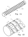
- Fig. 1A is a perspective view of a stent-graft constructed in accordance with the principles of the present invention.
- Fig. 1B is an enlarged perspective view of a mid-portion of the stent-graft shown in Fig. 1A.
- Fig. 1C is an enlarged perspective view of a portion of the stent-graft shown in Fig. 1A mounted on a cushioned mandrel.
- Fig. 2 is a side view of an enlarged portion of the stent-graft shown in Fig. 1A
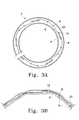
- Fig. 3A is a diagrammatic representation of a transverse section of the stent-graft of Fig. 1 prior to the coupling and graft members being secured to one another.
- Fig. 3B is an enlarged portion of the section shown in Fig. 3A after the coupling and graft members have been secured to one another.
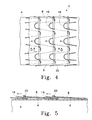
- Fig. 4 illustrates the stent-graft of Figs. 1A and 1B under longitudinal, axial compression.
- Fig. 5 is a sectional view of the stent-graft of Figs. 1A and 1B taken along line 5-5 in Fig. 4.
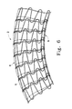
- Fig. 6 diagrammatically shows a portion of the stent-graft of Figs 1A and 1B bent along its longitudinal axis.
- Fig. 7 is a perspective view of another embodiment of the stent-graft of the present invention having an alternate stent to graft coupling configuration.
- Fig. 8 is a side view of an enlarged portion of the stent-graft shown in Fig. 7.
- Fig. 9 is a perspective view of a further embodiment of the stent-graft of the present invention having yet another stent to graft coupling.
- Fig. 10 is a side view of an enlarged portion of the stent-graft shown in Fig. 9.
- Fig. 11 is a partial view of the stent-graft of Fig. 1A showing an end portion of the device.
- Fig. 12 is an abstracted portion of a suitable stent and shows the concept of torsion on a portion of that stent.
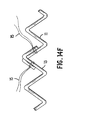
- Fig. 13A diagrammatically shows a further stent-member of the present invention with flared ends (the coupling tape drawn back to more clearly show the helically wound undulating stent configuration).
- Fig. 13B diagrammatically shows a further stent-member construction for supporting the graft member.
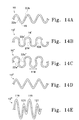
- Figs. 14A, 14B, 14C, 14D, 14E, and 14F are plan views of unrolled stent forms suitable for use in the invention.
- Figs. 15A, 15C and 15E show procedures for folding the stent-grafts.
- Figs. 15B, 15D, and 15F show the corresponding folded stent-grafts.
- Figs. 16A, 16B, and 16C diagrammatically show a procedure for deploying the stent-grafts using an external sleeve.
- Figs. 17A and 18A are partial perspective views of folded stent-grafts.
- Figs. 17B, 18C, 18B, and 18C are end views of the stent-grafts shown in Figs. 17A and 18A in folded and open states.
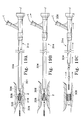
- Figs. 19A, 19B, and 19C diagrammatically show a procedure for deploying the stent-grafts shown in Figs. 17A-17C and 18A-18C using a tether wire.
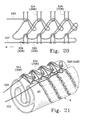
- Figs. 20 show a close-up view of a stent fold line using a preferred sack knot in the slip line.
- Fig. 21 is a diagrammatic perspective view of a folded stent-graft held in a position by a tether line and a sack knot as illustrated in Fig. 20.
- Fig. 22 shows an enlarged view of a stent fold line using another sack knot arrangement in the slip line.
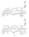
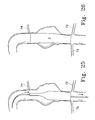
- Figs. 23, 24, 25, and 26 are diagrammatic sequential illustrations of a further deployment procedure.
- an expandable stent-graft 2 is shown constructed according to the principles of the present invention. Although particular stent and graft constructions will be described in conjunction with the preferred embodiments, it should be understood that other constructions may be used without departing from the scope of the invention.
- stent-graft 2 generally includes a thin-walled tube or graft member 4, a stent member 6 and a coupling member 8 for coupling the stent and graft members together.
- the stent and graft members are coupled together so that they are generally coaxial.
- Tubular expandable stent member 6 is generally cylindrical and comprises a helically arranged undulating member 10 having plurality of helical turns 12 and preferably comprising nitinol wire.
- the undulations preferably are aligned so that they are "in-phase" with each other as shown in Figs. 1A and 1B, for example.
- undulating helical member 10 forms a plurality of undulations 14, each including an apex portion 16 and a base portion 18.
- apex portions 16 in adjacent helical turns 12 are aligned so that an apex portion 16 may be displaced into a respective base portion 18 of a corresponding undulation in-phase therewith and in an adjacent helical turn.
- linking member 20 may be provided to maintain the phased relationship of the undulations during compression and deployment, and during bending of the stent member.
- linking member 20 is laced or interwoven between undulations in adjacent turns of the helical member and acquires a helical configuration (See, e.g., Figs. 1-3).
- Linking member 20 preferably comprises a biocompatible polymeric or metallic material having sufficient flexibility to be readily folded upon itself.
- Undulations 14 preferably are unconfined in that they are configured so as not to tend to inhibit the movement of flexible link 20 down between respective torsion arms or lengths 22a and 22b.
- the undulations preferably are configured and arranged so that a respective apex portion can readily move within a corresponding undulation base portion 18 in-phase therewith. It is believed that this construction minimizes the likelihood of stress build-up, for example, during bending or compression (as depicted in the lower portion of Fig. 6) and, thus, improves the kink resistance of the stent-graft.
- stent member 6 is disposed between generally tubular graft member 4 and coupling member 8.
- the stent member provides a support structure for the graft member to minimize the likelihood of the graft member collapsing during use.
- the graft member may surround the outer surface of the stent member, it preferably is placed within the stent member to provide a relatively smooth (wrinkles may form in the graft member between coupling member turns during compression) intralumental stent-graft surface as shown in the drawings.
- the coupling member which secures the stent member to the graft member, covers only a portion of the stent member.
- the coupling member can be described as preferably interconnecting less than entirely the inner or outer surface of the stent member to the graft member (e.g., it covers less than all of the outer surface of the stent member when the graft member is positioned inside the stent member). With this construction, regions of the stent member do not interface with the coupling member when the stent-graft is an uncompressed state, for example.
- the coupling member also preferably has a generally broad or flat surface for interfacing with the stent and graft members as compared to filament or thread-like structures such as sutures. This increases potential bonding surface area between the coupling member and the graft member to enhance the structural integrity of the stent-graph. The increased bonding surface area also facilitates minimizing the thickness of the coupling member. It has been found that a coupling member in a form of a generally flat ribbon or tape as shown in the drawings and designated with reference numeral 8, provides the desired results.
- coupling member 8 preferably is in the form of a generally flat ribbon or tape having at least one generally flat surface.
- coupling member 8 is arranged in a helical configuration according to the preferred embodiments illustrated in the drawings. Referring to Fig. 2, helically arranged coupling member 8 is formed with multiple helical turns 23, each being spaced from the turns adjacent thereto, thereby forming coupling member-free stress relief zones 24 between adjacent turns.
- the coupling member also preferably is arranged to provide a generally uniform distribution of stress relief zones 24.
- coupling member 8 is helically wound around the stent member with its helical turns 23 aligned with the stent member turns 12. As shown, the coupling member may be constructed with a constant width and arranged with uniform spacing between turns.
- Coupling member 8 also preferably covers a substantial portion of each undulation so as to minimize the likelihood of the stent member apexes lifting away from the graft member and interfering with their immediate environment.
- Coupling members having widths of 0.025, 0.050 and 0.075 inches have been applied to the illustrated stent member having a peak-to-peak undulation amplitude of about 0.075 inch with suitable results.
- the coupling member band width increases, the stent-graft flexibility generally is diminished. It is believed that coupling member width of about one-forth to three-fourths the amplitude of undulations 14, measured peak-to-peak, is preferred (more preferably about one third to two thirds that amplitude) to optimize flexibility.
- the coupling member width may be reduced without significantly sacrificing apex securement. Varying the width of the coupling member can also result in the adjustment of other structural properties. Increasing the width can also potentially increase the radial stiffness and the burst pressure and decrease the porosity of the device. Increasing band width can also diminish graft member wrinkling between coupling member turns.
- Coupling member 8 (or separate pieces thereof) also surrounds the terminal end portions of the stent-graft to secure the terminal portions of the graft member to the support structure formed by stent member 6 as shown in Fig. 11, for example.
- coupling member 8 may cover a substantial portion of each undulation as discussed above, apex portions 16 may still move within the undulations in-phase therewith as shown in Figs. 4-6 due primarily to the flexibility of coupling and linking members 8 and 20 respectively.
- coupling member 8 may be wrapped so as to be completely external to stent member 6 as shown in Figs. 1-6, interwoven above and below alternating undulations 14 as shown in Figs. 7 and 8, or interwoven above and below alternating undulation arms 22a and 22b as shown in Figs. 9 and 10.
- the ribbon-shaped tape or coupling member 8 may be axially spaced away from the apexes and linking member 20 (Figs.
- This spacing provides an area 28 in which linking member 20 can freely move without restraint, thereby reducing any resistance placed on apexes moving into corresponding undulations during compression or bending.
- the coupling member 8 may be wrapped (placed) on or interwoven with the undulations of the stent before or after it is positioned around the graft.
- the coupling member may be placed on or interwoven with the undulations of element 10 of Fig. 14A.
- FEP fluorinated ethylene propylene
- coupling member(s) arranged in a multiple helix may be used. Longitudinally extending strips of ribbon may be used and may be preferred when the coupling member is used in conjunction with other stent member configurations.
- Each undulation 14 alternatively may be described as a torsion segment and for purposes of the following discussion will be referred to as a torsion segment 14.
- a torsion segment 14 Referring to Fig. 12, an isolated undulation 14 is shown to facilitate the following discussion involving stent mechanics involved in deployment of the device.
- Each torsion segment includes an apex portion 16 and two adjacent torsion arms or lengths 22a and 22b extending therefrom.
- each torsion arm 22a & b will be a component of each of two adjacent torsion segments 14.
- torsion segment 14 undergoes a flexing in the amount of ⁇ ° apex portion 16 will flex some amount ⁇ °
- torsion arm 22a will undertake a twist of ⁇ °
- torsion arm 22b will undertake a twist opposite of that found in torsion arm 22a in the amount of ⁇ °.
- the amounts of angular torsion found in the torsion arms (22a & 22b) will not necessarily be equal because the torsion arms will not necessarily be equal because the torsion arms are not necessarily at the same angle to the longitudinal axis of the stent-member. Nevertheless, the sum of ⁇ ° + ⁇ ° + ⁇ ° will equal ⁇ °.
- the values of the other three angles are chosen by virtue of selection of number or torsion segments around the stent, size and physical characteristics of the wire, and length of the torsion areas (22a & b).
- Each of the noted angles must not be so large as to exceed the values at which the chosen material of construction plastically deforms at the chosen value of ⁇ °.
- torsion segment 14 undergoes a significant amount of flexing as the stent-member is folded or compressed in some fashion.
- the flexing provides a twist to the torsion arms (22a & b), a significant portion of which is generally parallel to the longitudinal axis of the stent.
- the described stent-member uses concepts which can be thought of as widely distributing and storing the force necessary to fold the tubular stent into a configuration which will fit through a diameter smaller than its relaxed outside diameter without inducing plastic deformation of the constituent metal or plastic and yet allowing those distributed forces to expand the stent upon deployment.
- Stent-graft 2 iv includes stent member 6' which is the same as stent member 6 with the exception that it includes flared end portions 142 at one or both ends. Flared end portions 142 provide secure anchoring of the resulting stent-graft 2 iv against the vessel wall and prevents the implant from migrating downstream. In addition, flared end portions 142 provide a tight seal against the vessel so that the blood is channeled through the lumen rather than outside the graft.
- the undulating structure may vary in spacing to allow the helical turns to maintain their phased relationship as discussed above. Although a linking member between the continuous helical turns is not shown, such structure preferably is included to maintain the alignment of the apexes as discussed above.
- the graft support structure also may be made by forming a desired structural pattern out of a flat sheet. The sheet may then be rolled to form a tube.
- the stent also may be machined from tubing. If the chosen material is nitinol, careful control of temperature during the machining step may be had by EDM (electro-discharge-machining), laser cutting, chemical machining, or high pressure water cutting.
- the stent-member (graft support structure) may comprise multiple tubular members or sections 50, each coupled to the graft-member 4 with a coupling member as described above.
- Tubular members or sections 50 may have various construction and, thus, may be configured to have the same construction as the stent-member 6 shown in Figs. 1-11, for example.
- Tubular members also may be directly coupled to each other (e.g., with bridging element(s) extend between adjacent sections as would be apparent to one of ordinary skill) or, indirectly coupled to each other through their interconnection with the graft member.
- Fig. 14A shows the sinusoidal shaped undulating member 10 described above. Adjacent torsion arms 22a & b are not parallel.
- Fig 14B shows an undulating member 10' having generally U-shaped undulations or torsion members where the torsion arms are generally parallel.
- Fig 14C shows a further variation where undulating member 10" includes ovoid shaped undulations or torsion segments. In this variation, adjacent torsion arms 22" a & b are again not parallel, but generally form an open-ended oval.
- Fig. 14D shows another variation where undulating member 10"' includes V-shaped torsion members.
- Fig. 14E shown undulating member 10 iv in which adjacent undulations have different amplitudes.
- the peaks of the large amplitude torsion segments 119 may be lined up "out of phase” or “peak to peak” with small or large amplitude torsion segments 110, 121, respectively, in the adjacent turn of the helix or may be positioned "in phase” similar to those discussed with regard to Figs. 1A and B above.
- the configurations shown in Figs. 14 A - 14E are exceptionally kink-resistant and flexible when flexed along the longitudinal axis of the stent-member.
- Fig. 14F shows a stent formed from sections 11 and 13 which are connected to one another by sutures 15.
- the stent member preferably is oriented coaxially with the tubular graft member.
- the stent member may be placed within the graft member, it preferably is placed on the outer surface of the graft member so that a relatively smooth graft wall interfaces with the blood.
- an additional graft member may be placed on the outer surface of the stent-graft illustrated in the drawings.
- the stent structure should have the strength and flexibility to urge the graft tubing firmly against the vessel wall so that the graft member conforms with the inner surface of the vessel wall.
- the graft member preferably is impermeable to blood at normal or physiologic blood pressures. The impermeability makes the stent-graft suitable for shunting and thereby hydraulically isolating aneurysms.
- the stent member is constructed of a reasonably high strength material, i.e., one which is resistant to plastic deformation when stressed.
- the stent member comprises a wire which is helically wound around a mandrel having pins arranged thereon so that the helical turns and undulations can be formed simultaneously.
- Other constructions also may be used.
- an appropriate shape may be formed from a flat stock and wound into a cylinder or a length of tubing formed into an appropriate shape.
- the stent material should have a high strength-to-volume ratio.
- Use of designs as depicted herein provides stents which may be longer in length than conventional designs. Additionally, the designs do not suffer from a tendency to twist (or helically unwind) or to shorten as the stent-graft is deployed.
- materials suitable in these stents and meeting these criteria include various metals and some polymers.
- a percutaneously delivered stent-graft must expand from a reduced diameter, necessary for delivery, to a larger deployed diameter.
- the diameters of these devices obviously vary with the size of the body lumen into which they are placed.
- the stents of this invention may range in size from 2.0mm in diameter (for neurological applications) to 40mm in diameter (for placement in the aorta). A range of about 2.0mm to 6.5mm (perhaps to 10.0mm) is believed to be desirable.
- expansion ratios of 2:1 or more are required.
- These stents are capable of expansion ratios of up to 5:1 for larger diameter stents.
- Typical expansion ratios for use with the stents-grafts of the invention typically are in the range of about 2:1 to about 4:1 although the invention is not so limited.
- the thickness of the stent materials obviously varies with the size (or diameter) of the stent and the ultimate required yield strength of the folded stent. These values are further dependent upon the selected materials of construction.
- Wire used in these variations are typically of stronger alloys, e.g., nitinol and stronger spring stainless steels, and have diameters of about 0.002 inches to 0.005 inches.
- the appropriate diameter for the stent wire may be somewhat larger, e.g., 0.005 to 0.020 inches.
- stent flat stock For flat stock metallic stents, thickness of about 0.002 inches to 0.005 inches is usually sufficient. For the larger stents, the appropriate thickness for the stent flat stock may be somewhat thicker, e.g., 0.005 to 0.020 inches.
- the stent-graft is fabricated in the expanded configuration. In order to reduce its diameter for delivery the stent-graft would be folded along its length, similar to the way in which a PCTA balloon would be folded. It is desirable, when using super-elastic alloys which also have temperature-memory characteristics, to reduce the diameter of the stent at a temperature below the transition-temperature of the alloys. Often the phase of the alloy at the lower temperature is somewhat more workable and easily formed. The temperature of deployment is desirably above the transition temperature to allow use of the super-elastic properties of the alloy.
- Jervis in U.S. Pat. Nos. 4,665,906 and 5,067,957, describes the use of shape memory alloys having stress-induced martensite properties in medical devices which are implantable or, at least, introduced into the human body.
- Nitinol is especially preferred because of its "super-elastic" or "pseudo-elastic" shape recovery properties, i.e., the ability to withstand a significant amount of bending and flexing and yet return to its original form without deformation.
- These metals are characterized by their ability to be transformed from an austenitic crystal structure to a stress-induced martensitic structure at certain temperatures, and to return elastically to the austenitic shape when the stress is released.
- These alternating crystalline structures provide the alloy with its super-elastic properties. These alloys are well known but are described in U.S. Pat. Nos. 3,174,851, 3,351,463, and 3,753,700.
- nitinol will be nominally 50.6% ( ⁇ 0.2%) Ni with remainder Ti.
- Commercially available nitinol materials usually will be sequentially mixed, cast, formed, and separately cold-worked to 30-40%, annealed, and stretched. Nominal, ultimate yield strength values for commercial nitinol are in the range of 30 psi and for Young's modulus are about 700 Kbar.
- the '700 patent describes an alloy containing a higher iron content and consequently has a higher modulus than the Ni-Ti alloys.
- Nitinol is further suitable because it has a relatively high strength to volume ratio. This allows the torsion members to be shorter than for less elastic metals.
- the flexibility of the stent-graft is largely dictated by the length of the torsion segments and/or torsion arms. The shorter the pitch of the device, the more flexible the stent-graft structure can be made.
- Materials other than nitinol are suitable. Spring tempered stainless steels and cobalt-chromium alloys such as ELGILOY are also suitable as are a wide variety of other known "super-elastic" alloys.
- Nitinol is preferred in this service because of its physical properties and its significant history in implantable medical devices, we also consider it also to be useful in a stent because of its overall suitability with magnetic resonance imaging (MRI) technology. Many other alloys, particularly those based on iron, are an anathema to the practice of MRI causing exceptionally poor images in the region of the alloy implant. Nitinol does not cause such problems.
- thermotropic liquid crystal polymers are high molecular weight materials which can exist in a so-called “liquid crystalline state” where the material has some of the properties of a liquid (in that it can flow) but retains the long range molecular order of a crystal.
- thermotropic refers to the class of LCP's which are formed by temperature adjustment. LCP's may be prepared from monomers such as p,p'-dihydroxy-polynuclear-aromatics or dicarboxy-polynuclear-aromatics.
- the LCP's are easily formed and retain the necessary interpolymer attraction at room temperature to act as high strength plastic artifacts as are needed as a foldable stent. They are particularly suitable when augmented or filled with fibers such as those of the metals or alloys discussed below. It is to be noted that the fibers need not be linear but may have some preforming such as corrugations which add to the physical torsion enhancing abilities of the composite.
- Flexible link 20 which is slidably disposed between adjacent turns of the helix may be of any appropriate filamentary material which is blood compatible or biocompatible and sufficiently flexible to allow the stent to flex and not deform the stent upon folding.
- the linkage may be a single or multiple strand wire (platinum, platinum/tungsten, gold, palladium, tantalum, stainless steel, etc.), much preferred in this invention is the use of polymeric biocompatible filaments.
- Synthetic polymers such as polyethylene, polypropylene, polyurethane, polyglycolic acid, polyesters, polyamides, their mixtures, blends and copolymers are suitable; preferred of this class are polyesters such as, polyethylene terephthalate including DACRON and MYLAR and polyaramids such as KEVLAR, polyfluorocarbons such as polytetrafluoroethylene with and without copolymerized hexafluoropropylene, TEFLON or ePTFE, and porous or nonporous polyurethanes. Natural materials or materials based on natural sources such as collagen may also be used in this service.
- the tubular component or graft member of the stent-graft may be made up of any material which is suitable for use as a graft in the chosen body lumen.
- Many graft materials are known, particularly known are those used as vascular graft materials.
- natural materials such as collagen may be introduced onto the inner surface of the stent and fastened into place.
- Desirable collagen-based materials include those described in U.S. Pat. No. 5,162,430, to Rhee et al, and WO 94/01483 (PCT/US93/06292), the entirety of which are incorporated by reference.
- Synthetic polymers such as polyethylene, polypropylene, polyurethane, polyglycolic acid, polyesters, polyamides, their mixture, blends, copolymers, mixtures, blends and copolymers are suitable, preferred of this class are polyesters such as polyethylene terephthalate including DACRON and MYLAR and polyaramids such as KEVLAR, polyfluorocarbons such as polytetrafluoroethylene (PTFE) with and without copolymerized hexafluoropropylene, expanded or not-expanded PTFE, and porous or nonporous polyurethanes.
- PTFE polytetrafluoroethylene
- PTFE polytetrafluoroethylene
- FEP fluorinated ethylene propylene
- TFE tetrafluorethylene
- PFA perfluoro (propyl vinyl ether)
- PCTFE polychlorotrifluoroethylene
- ECTFE ethylene-chlorotrifluoroethylene
- ETFE polyvinylidene fluoride
- PVDF polyvinylidene fluoride
- PVF polyvinyfluoride
- radio-opaque metallic fibers such as gold, platinum, platinum-tungsten, palladium, platinum-iridium, rhodium, tantalum, or alloys or composites of these metals like may be incorporated into the device, particularly, into the graft, to allow fluoroscopic visualization of the device.
- the tubular component may also be reinforced using a network of small diameter fibers.
- the fibers may be random, braided, knitted or woven.
- the fibers may be imbedded in the tubular component, may be placed in a separate layer coaxial with the tubular component, or may be used in a combination of the two.
- a preferred material for the graft and coupling members is porous expanded polytetrafluorethylene.
- An FEP coating is one preferred adhesive that is provided on one side of the coupling member.
- the stent member wire is helically wound around a mandrel having pins positioned thereon so that the helical structure and undulations can be formed simultaneously. While still on the mandrel, the stent member is heated to about 460°F for about 20 minutes so that it retains its shape.
- Wire sizes and materials may vary widely depending on the application.
- the following is an example construction for a stent-graft designed to accommodate 6mm diameter vessel lumen.
- the stent member comprises a nitinol wire (50.8 atomic % Ni) having a diameter of about 0.007 inch.
- the wire is formed to have sinusoidal undulations, each having an amplitude measured peak-to-peak of about 0.100 inch and the helix is formed with a pitch of about 10 windings per inch.
- the inner diameter of the helix (when unconstrained) is about 6.8mm.
- the nitinol wire may be polished if desired.
- the wire is fed through an electrolytic bath having an applied potential to electrolytically clean, passivate and polish the wire.
- the polishing reduces the availability of surface nickel for extraction or corrosion.
- Suitable electrolytic treating materials for the bath are commercially available.
- One such source of a commercially available electrolytic treating material is NDC (Nitinol Devices and Components.
- the linking member can be arranged as shown in the drawings and may have a diameter of about 0.006 inch.
- the graft member is porous expanded polytetrafluorethylene (PTFE), while the coupling member is expanded PTFE coated with FEP.
- the coupling member is in the form of a flat ribbon (as shown in the illustrative embodiments) that is positioned around the stent and graft members as shown in Figs. 1-3.
- the side of the coupling member or ribbon that is FEP coated faces the graft member to secure it to the graft member.
- the intermediate stent-graft construction is heated to allow the materials of the ribbon and graft member to merge and self-bind as will be described in more detail below.
- the FEP-coated porous expanded PTFE film used to form the ribbon shaped coupling member preferably is made by a process which comprises the steps of:
- thermoplastic polymers including thermoplastic fluoropolymers may also be used to make this coated film.
- the adhesive coating on the porous expanded PTFE film may be either continuous (non-porous) or discontinuous (porous) depending primarily on the amount and rate of stretching, the temperature during stretching, and the thickness of the adhesive prior to stretching.
- the thin wall expanded PTFE graft used to construct this example contains an inner tube of PTFE and an outer helical wrap of PTFE.
- the graft was about 0.1mm (0.004 in) thickness and had a density of about 0.5g/cc.
- the microstructure of the porous expanded PTFE contained fibrils of about 25 micron length.
- a 3cm length of this graft material was placed on a mandrel the same diameter as the inner diameter of the graft.
- a cushioning layer 5 was placed on the mandrel 3 prior to placement of the graft 4.
- the nitinol stent member having about a 3cm length was then carefully fitted over the center of the thin wall graft 4 and extended to its desired length. Any struts out of phase should be placed in phase prior to applying the coupling member.
- the stent-member was then provided with a ribbon shaped coupling member comprised of the FEP coated film as described above.
- the coupling member was helically wrapped around the exterior surface of the stent-member as shown in Figs. 1-6.
- the uniaxially-oriented fibrils of the microstructure of the helically-wrapped ribbon were helically-oriented about the exterior of stent surface.
- the ribbon shaped coupling member was oriented so that its FEP-coated side faced inward and contacted the exterior of surface of the stent-member. This ribbon surface was exposed to the outward facing surface of the thin wall graft member exposed through the openings in the stent member.
- an outer, multi-component sheath 9, formed by a longitudinally slit tube of non-adhering PTFE and an outer helical wrap of non-adhering PTFE is placed around the stent-graft-coupling member assembly to compress the assembly onto the mandrel (Fig. 1C).
- sheath 9 may be formed by helically wrapping PTFE around the stent-graft-coupling assembly without the longitudinally slit tube.
- the mandrel assembly was placed into an oven set at 315°C for a period of 15 minutes after which the film-wrapped mandrel was removed from the oven and allowed to cool. Following cooling to approximately ambient temperature, the mandrel, as well as the cushioning layer and outer compression tube, was removed from the resultant stent-graft. The amount of heat applied was adequate to melt the FEP-coating on the porous expanded PTFE film and thereby cause the graft and coupling members to adhere to each other.
- the graft member was adhesively bonded to the inner surface of helically-wrapped coupling member 8 through the openings between the adjacent wires of the stent member.
- the combined thickness of the luminal and exterior coverings (graft and coupling members) and the stent member was about 0.4mm.
- the stent-graft was then folded in order to prepare it for delivery.
- a stainless steel wire which was a couple of inches longer than the stent-graft was inserted through the lumen of the stent-graft.
- the stent-graft was flattened and the stainless steel wire positioned at one end of the stent-graft.
- a second stainless wire of about the same length was placed on the outer surface of the stent-graft adjacent to the first stainless steel wire.
- the wires were then mounted together into a fixture, tensioned and then rotated, thereby folding the stent-graft as shown in Figs. 15 C & D which will be discussed in more detail below.
- the stent-graft As the stent-graft rotates it is pressed into a "C" shaped elongated stainless steel clip in order to force it to roll upon itself. The folded stent-graft is then advanced along the wire out of the clip into a glass capture tube. A removable tether line, which is used to constrain the stent-graft in the rolled configuration for delivery, as will be discussed in more detail below, is applied to the stent-graft at this point by gradually advancing the stent-graft out of the capture tube and lacing the tether line through the stent-graft structure. After this step is completed, the stent-graft is pulled off of the first wire and transferred onto the distal end of the catheter shaft or tubing for delivery.
- the stent-graft Prior to folding, the stent-graft was cooled to about -30°C so that the nitinol was fully martensitic and, thus, malleable. This is done to allow the stent-graft to be more easily folded. Cooling is accomplished by spray soaking the graft with chilled gas such as tetrafluroethane. Micro-DustTM dry circuit duster manufactured by MicroCave Corporation (Conn) provides suitable results. The spray canister was held upside down to discharge the fluid as a liquid onto the stent-graft.
- the stent-graft may be delivered percutaneously, typically through the vasculature, after having been folded to a reduced diameter. Once reaching the intended delivery site, it is expanded to form a lining on the vessel wall.
- a stent-graft having torsion members As described above, is folded, crushed, or otherwise collapsed, mechanical energy is stored in torsion in those members.
- the torsion members In this loaded state, the torsion members have a torque exerted by the torsion members as folded down to a reduced diameter must be restrained from springing open.
- the stent-member preferably has at least one torsion member per fold.
- the stent-graft is folded along its longitudinal axis and restrained from springing open.
- the stent-graft is then deployed by removing the restraining mechanism, thus allowing the torsion members to spring open against the vessel wall.
- the stent grafts of this invention are generally self-opening once deployed. If desired, an inflatable balloon catheter or similar means to ensure full opening of the stent-graft may be used under certain circumstances.
- the attending physician will select an appropriately sized stent-graft.
- the stent-graft will be selected to have an expanded diameter of up to about 10% greater than the diameter of the lumen at the deployment site.
- Fig. 15A diagrammatically illustrates a folding sequence for folding a stent-graft constructed according to the present invention.
- the stent-graft generally designated with reference numeral 200 is positioned about a guidewire 232 and folded into a loose C-shaped configuration.
- Fig. 15B shows a diagrammatic perspective view of the resulting folded stent-graft.
- Figs. 15C & E show further folding sequences.
- Figs. 15D & F show diagrammatic perspective views of the resulting folded stent-grafts showing the rolled and triple lobed configurations, respectively. The rolled configuration is preferred.
- FIGs. 16A-16C diagrammatically illustrate deployment procedures for the present invention.
- Fig. 16A shows an example target site having a narrowed vessel lumen.
- a guidewire 208 having a guide tip has been directed to the site using known techniques.
- the stent-graft 210 is mounted on guidewire tubing 212 inside outer sliding sheath 214 after having been folded in the manner discussed above.
- the outer sliding sheath 214 binds the compressed stent-graft 210 in place until released.
- Fig. 16B shows placement of the stent-graft 120 at the selected site by sliding the stent-graft over the guidewire all together with the guidewire tubing 212 and the outer sliding sheath 214.
- the stent-graft is deployed by holding the guidewire tubing 212 in a stationary position while withdrawing the outer sliding sheath 214.
- Fig. 16B shows the stent-graft partially deployed
- Fig. 16C shows the stent-graft fully deployed after the guidewire tubing and the outer sliding sheath have been fully retracted.
- Figs. 17A-C, 18A-C, and 19A-C show deployment variations for deploying a stent-graft constructed according to the present invention. These methods involve the use of a control line or tether line which maintains the stent or stent-graft in a folded configuration until release.
- stent-graft 302 is shown folded about guidewire 304 so that, when deployed, the guidewire 304 is within stent-graft 302.
- a tether wire 306 is passed through loops 308 which preferably are formed by pulling the linking member discussed above away from the stent structure.
- tether wire 306 is removed by sliding it axially along the stent-graft and out of loops 308, the stent-graft unfolds into a generally cylindrical shape.
- Figs. 18A & B stent-graft 302 is shown in a rolled pre-deployment configuration. In this case, guidewire 304 is inside the stent.
- the stent-graft assumes the form shown in Fig. 18C.
- Figs. 19A-C diagrammatically show additional procedures for deploying a stent-graft of the present invention using a percutaneous catheter assembly 314.
- catheter assembly 314 has been inserted to a selected site within a body lumen.
- Stent-graft 312 is folded about guidewire 319 and guidewire tube 318 held axially in place prior to deployment by distal barrier 320 and proximal barrier 322.
- the distal and proximal barriers typically are affixed to the guidewire tube 318.
- Tether wire 306 is extends through loops 308 proximally through the catheter assembly's 314 outer jacket 324 through to outside the body.
- FIG. 19B shows partial removal of tether wire 306 from loops 308 to partially expand the stent-graft 312 onto the selected site.
- Fig. 19C shows complete removal of the tether wire, the loops and retraction of the catheter assembly 314 from the interior of the stent-graft which is fully expanded.
- Fig. 20 shows a close-up of a stent fold line having the familiar herringbone pattern of the preferred "sack knot" used to close the fold in the stent.
- This knot is the one used to hold, e.g., burlap sacks of feed grain closed prior to use and yet allow ease of opening when the sack is to be opened.
- the slip line has a fixed end 320 and a release end 322. Loops of the slip line pass through the eyelets 324 on the side of the stent fold associated with the fixed end 320 and are held in place by eyelets 326 on the side of the stent fold associated with the release end 322.
- the fixed end 320 is not typically tied to the stent so to allow removal of the slip line after deployment.
- the eyelets 324 and 326 are desirable but optional.
- the eyelets 324 and 326 may be wire or polymeric thread or the like tied to the stent structure at the edge of the stent fold. If so desired, the loops may be dispensed with and the slip line woven directly into the stent structure.
- the self-expanding stent may be deployed by pulling axially on release end 322 as shown by the arrow in the drawing.
- Fig. 21 is a diagrammatic perspective view of a folded stent-graft using the knot shown in Fig. 20.
- Fig. 21 shows the use of a single stent fold similar in configuration to those described above.
- the fixed end portion 320 of the slip line is associated with a row of eyelets 324 which preferably are formed by pulling local portions of linking member 20 away from the fold line, threading the slip line therethrough and then releasing the respective portion of the linking member.
- the eyelets may be tied or otherwise fixed to the stent.
- the release end 322 is associated with the other row of eyelets 326.
- release end 322 also is positioned so that when the release mechanism is associated with the stent-graft, release end 322 is in the vicinity of the proximal portion of the stent-graft.
- release end 322 is pulled, the stent-graft unfolds from the proximal to the distal end (i.e., opposite to that shown in Figs. 16B and 19B, for example).
- this arrangement eliminates the extra folded-back length of the tether line leading to release end 322 and may reduce the likelihood of snagging between the tether or slip line and the stent member.
- This arrangement also may provide less fluid flow resistance when eh stent-grath is deployed against the flow of blood which may improve positioning accuracy during deployment.
- stent-graft deployment is described using a catheter for percutaneous delivery, it should be understood that other deployment techniques may be used.
- the folded stent-graft may also be deployed through artificial or natural body openings with a sheath or endoscopic delivery device, for example, and perhaps, without a guidewire.
- the stent-graft may be delivered manually during a surgical procedure.
- the stent-graft of the present invention may be used, for example, to reinforce vascular irregularities and provide a smooth nonthrombogenic interior vascular surface for diseased areas in blood vessels, or to increase blood flow past a diseased area of a vessel by mechanically improving the interior surface of the vessel.
- the inventive stent-graft is especially suitable for use within smaller vessels between 2mm and 6mm in diameter but is equally suitable for significantly larger vessels.
- the inventive stent-graft may be self-expanded so that it may be percutaneously delivered in a folded state on an endovascular catheter or via surgical or other techniques and then expanded.
- the stent-graft construction described above also provides a variable length stent-graft. This is especially advantageous during implantation procedures.
- stent-graft design of the present invention allows the physician to adjust its length during deployment allowing more accurate placement of the device.
- stent-graft is a single tubular design, placed into the thoracic aorta 70, and will be located between the renal arteries and the T-7 artery.
- the direction of deployment will be from renals 'upstream' to the T-7 artery.
- the device will be supplied in its longest state with shortening capability during deployment (the inverse where a compressed stent-graft is deployed also is possible).
- the physician estimates the length required, and chooses a device which is at least as long, and usually slightly longer than the estimated length.
- the stent-graft is inserted through an introducer as is conventional in the art. It is advanced until its distal ends 2a is located as desired near the renal arteries (72) (Fig. 22). At this point, the proximal end of the stent-graft would be located at or past the T-7 artery (74).
- the stent-graft deployment is initiated slowly, distal to proximal ('downstream to upstream') (Fig. 23) while watching the proximal end location on fluoroscopy.
- the delivery catheter 76 which is of conventional construction, would be pulled toward the operator, shortening the stent-graft to keep the proximal end in the correct location. This shortening can occur as long as the portion of the stent-graft being compressed is within the aneurysm 78. Once the proximal end is correctly located (Fig. 25), the stent graft is fully deployed, and the delivery catheter is removed (Fig. 26).
Abstract
Description
Claims (43)
- A stent-graft comprising:a stent member having an inner surface and an outer surface;a generally tubular graft member; anda ribbon adherred in contact with at least one of the inner and outer surfaces of said stent member and forming multiple strips spaced from one another, the ribbon securing the stent member and graft member to one another.
- The stent-graft of claim 1 wherein said stent member comprises a tubular member.
- The stent-graft of claim 2 wherein said stent member comprises multiple tubular members.
- The stent-graft of claim 1 wherein said stent member comprises a first member having undulations and being arranged in a helical configuration with multiple turns.
- The stent-graft of claim 4 wherein said ribbon is arranged in a helical configuration with multiple turns, each turn being spaced from an adjacent turn and forming one of said multiple strips.
- The stent-graft of claim 5 wherein said spacing between said turns is uniform.
- The stent-graft of claim 5 wherein said ribbon covers a portion of said undulations.
- The stent-graft of claim 5 wherein said ribbon is interwoven into at least one of said undulations.
- The stent-graft of claim 5 further including a linking member threaded between adjacent turns to maintain undulations in adjacent turns generally in-phase with one another.
- The stent-graft of claim 9 wherein a number of said undulations are configured to permit therein unrestrained movement of an undulation generally in-phase therewith.
- The stent-graft of claim 5 wherein a group of said undulations forms a sinusoidal curve.
- The stent-graft of claim 5 wherein said ribbon has a width less than or equal to about two-thirds the average amplitude, measured peak-to-peak, of one of said undulations.
- The stent-graft of claim 12 wherein said ribbon has a width less than or equal to about three-fourths the average amplitude, measured peak-to-peak, of one of said undulations.
- The stent-graft of claim 1 wherein said graft member has an average thickness of less than or equal to about 0.006 inch.
- The stent-graft of claim 14 wherein said ribbon has an average thickness of less than or equal to about 0.005 inch.
- The stent-graft of claim 1 wherein said graft member comprises a fluoropolymer.
- The stent-graft of claim 16 wherein said fluoropolymer comprises porous expanded polytetrafluorethylene.
- The stent-graft of claim 1 wherein said graft member contains radiopaque fibers.
- The stent-graft of claim 1 wherein said stent member comprises a nickel-titanium alloy.
- The stent-graft of claim 1 wherein said ribbon is adhesively bonded to said graft member.
- The stent-graft of claim 1 wherein said ribbon has a generally flat portion that faces said graft member.
- A stent-graft comprising:a stent member having an inner surface and an outer surface;a generally tubular graft member having an inner and an outer surface, one of said stent and graft members surrounding at least a portion of the other; anda ribbon interconnecting less than entirely one of said inner and outer surfaces of said graft member to said stent member.
- The stent-graft of claim 22 wherein said ribbon is arranged to include multiple helical turns, at least one of said turns being spaced from a turn adjacent thereto.
- The stent-graft of claim 22 wherein said ribbon has a generally flat portion that faces said graft member.
- The stent-graft of claim 22 wherein said stent member is tubular, said stent and graft member are generally coaxial, and said graft member is disposed in said stent member.
- A stent-graft comprising:a stent member having an inner surface and an outer surface, said stent member including a first member and a second member, said first member being arranged in a helical configuration with multiple helical turns, said second member coupling adjacent helical turns;a generally tubular graft member having an inner surface and an outer surface, one of said stent and graft members surrounding at least a portion of the other, anda coupling member coupling less than entirely one of said inner and outer surfaces of said graft member to said stent member.
- The stent-graft of claim 26 wherein said first member includes multiple undulations, each having an apex, said coupling member is helically arranged and spaced from said apexes to form therewith respective openings, said apexes being configured to permit unrestrained movement of said second member within said openings.
- A stent-graft comprising:a generally tubular stent member having inner and outer circumferences, said stent member including a first member being arranged in a helical configuration with multiple helical turns and having multiple undulations, each undulation having an apex,a flat ribbon helically arranged and disposed to contact at least one of said inner and outer circumferences of said stent member and forming multiple windings spaced from one another; anda generally tubular graft member disposed within said stent member portions of which are secured to said ribbon.
- The stent-graft of claim 28 wherein said helically wound ribbon is generally spaced from said apexes and forms therewith respective openings, said apexes being configured to permit unrestrained movement of said second member within said openings.
- A method of deploying a stent-graft comprising the steps of:placing a first end of a variable length stent-graft having an inner graft member, an outer, helically wound stent coupled to said graft member by a helically wound ribbon with spaced apart turns, at a first site in a mammal; moving the second end of the stent-graft toward a second site in a mammal; lengthening the stent-graft if the second end does not reach the second site; andshortening of the stent-graft if the second end extends beyond the second site.
- A process for making a stent graft comprising:(a) placing a graft around a mandrel;(b) positioning a stent having undulations around said graft; and(c) covering a portion of said stent and graft with a coupling member having a flat surface, to form a stent-graft assembly.
- The process according to claim 31 further comprising the step of:
(a1) prior to step (a), placing a cushioning layer around the mandrel. - The process according to claim 31, wherein said covering step comprises helically wrapping the coupling member around the stent whereby adjacent turns of the helically wrapper coupling member are spaced from one another.
- The process according to claim 32, wherein said covering step comprises helically wrapping the coupling member around the stent whereby adjacent turns of the helically wrapper coupling member are spaced from one another.
- The process according to claim 32 wherein the coupling member is bonded to an outer surface of the graft.
- The process according to claim 31 further comprising the step of:
(d) placing a sheath around the assembly of step (c) to form a compressed assembly. - The process according to claim 35 further comprising the step of:
(e) heating the tensioned assembly of step (d) to bond the coupling member to the graft. - The process according to claim 34 further comprising:(d) placing a tubular sheath having a longitudinal slit around the assembly of step (c); and(e) helically wrapping a film around the sheath to compress the assembly.
- The processing according to claim 36 wherein the sheath includes a helical wrapping of PTFE film.
- The stent-graft of claim 16 wherein one side of said ribbon has a coating of a fluorinated ethylene propylene polymer.
- An device compromising;a generally tubular support member having inner and outer circumferences, said support member having multiple undulations, each having an amplitude;a generally tubular graft member disposed within said support member; anda fluoropolymer tape helically arranged to contact at least one of said inner and outer circumferences of said support member and forming multiple windings spaced from one another, each winding covering only a portion of the amplitude of the undulations.
- A stent-grafted comprising;a generally tubular stent member having inner and outer circumferences, said stent member having multiple undulations, each having an amplitude;a generally tubular graft member disposed within said stent member; anda fluoropolymer tape helically arranged to contact at least one of said inner and outer circumferences of said stent member and forming multiple windings spaced from one another, each winding covering only a portion of the amplitude of the undulations.
- A device compromising;a stent member having multiple undulations, each having an amplitude;a generally tubular graft member at least disposed within said stent member; anda helically arranged tape to forming multiple spaced windings from one another, each winding covering only a portion of the amplitude of the undulations.
Priority Applications (1)
| Application Number | Priority Date | Filing Date | Title |
|---|---|---|---|
| EP20040007188 EP1477129A3 (en) | 1997-07-18 | 1998-07-16 | Kink resistant stent-graft |
Applications Claiming Priority (2)
| Application Number | Priority Date | Filing Date | Title |
|---|---|---|---|
| US896805 | 1997-07-18 | ||
| US08/896,805 US6042605A (en) | 1995-12-14 | 1997-07-18 | Kink resistant stent-graft |
Related Child Applications (1)
| Application Number | Title | Priority Date | Filing Date |
|---|---|---|---|
| EP20040007188 Division EP1477129A3 (en) | 1997-07-18 | 1998-07-16 | Kink resistant stent-graft |
Publications (3)
| Publication Number | Publication Date |
|---|---|
| EP0893108A2 true EP0893108A2 (en) | 1999-01-27 |
| EP0893108A3 EP0893108A3 (en) | 2000-03-01 |
| EP0893108B1 EP0893108B1 (en) | 2007-01-03 |
Family
ID=25406876
Family Applications (2)
| Application Number | Title | Priority Date | Filing Date |
|---|---|---|---|
| EP98305680A Expired - Lifetime EP0893108B1 (en) | 1997-07-18 | 1998-07-16 | Process for making a kink-resistant stent-graft |
| EP20040007188 Withdrawn EP1477129A3 (en) | 1997-07-18 | 1998-07-16 | Kink resistant stent-graft |
Family Applications After (1)
| Application Number | Title | Priority Date | Filing Date |
|---|---|---|---|
| EP20040007188 Withdrawn EP1477129A3 (en) | 1997-07-18 | 1998-07-16 | Kink resistant stent-graft |
Country Status (5)
| Country | Link |
|---|---|
| US (4) | US6042605A (en) |
| EP (2) | EP0893108B1 (en) |
| AT (1) | ATE349972T1 (en) |
| DE (1) | DE69836780T2 (en) |
| ES (1) | ES2279561T3 (en) |
Cited By (50)
| Publication number | Priority date | Publication date | Assignee | Title |
|---|---|---|---|---|
| WO2000045743A1 (en) * | 1999-02-02 | 2000-08-10 | Impra, Inc. | Partial encapsulation of stents using strips and bands |
| WO2000071057A1 (en) * | 1999-05-20 | 2000-11-30 | Scimed Life Systems, Inc. | Stent-graft with increased flexibility |
| WO2001001887A1 (en) * | 1999-07-02 | 2001-01-11 | Scimed Life Systems, Inc. | Improved composite vascular graft |
| US6183481B1 (en) | 1999-09-22 | 2001-02-06 | Endomed Inc. | Delivery system for self-expanding stents and grafts |
| WO2000049973A3 (en) * | 1999-02-26 | 2001-03-22 | Vascular Architects Inc | Coiled stent and catheter assembly |
| US6238430B1 (en) | 1999-02-26 | 2001-05-29 | Vascular Architects, Inc. | Catheter assembly with controlled release endoluminal prosthesis and method for placing |
| US6402779B1 (en) | 1999-07-26 | 2002-06-11 | Endomed, Inc. | Balloon-assisted intraluminal stent graft |
| US6409750B1 (en) | 1999-02-01 | 2002-06-25 | Board Of Regents, The University Of Texas System | Woven bifurcated and trifurcated stents and methods for making the same |
| US6673103B1 (en) | 1999-05-20 | 2004-01-06 | Scimed Life Systems, Inc. | Mesh and stent for increased flexibility |
| US6770087B2 (en) | 1999-02-02 | 2004-08-03 | Bard Peripheral Vascular, Inc. | Partial encapsulation of stents |
| US6792979B2 (en) | 1999-02-01 | 2004-09-21 | Board Of Regents, The University Of Texas System | Methods for creating woven devices |
| US6945991B1 (en) * | 2000-11-28 | 2005-09-20 | Boston Scientific/Scimed Life Systems, Inc. | Composite tubular prostheses |
| US6974473B2 (en) | 2000-06-30 | 2005-12-13 | Vascular Architects, Inc. | Function-enhanced thrombolytic AV fistula and method |
| WO2007002331A1 (en) * | 2005-06-23 | 2007-01-04 | Boston Scientific Scimed, Inc. | Eptfe lamination-resizing eptfe tubing |
| WO2007028452A1 (en) | 2005-07-19 | 2007-03-15 | Aesculap Ag & Co. Kg | Stent-graft prosthesis |
| WO2007100456A1 (en) * | 2006-03-01 | 2007-09-07 | Boston Scientific Scimed, Inc. | Flexible stent-graft devices and methods of producing the same |
| WO2008156683A1 (en) * | 2007-06-13 | 2008-12-24 | Med Institute, Inc. | Stent attachment for endovascular aneurysm repair |
| US8337650B2 (en) | 1995-03-10 | 2012-12-25 | Bard Peripheral Vascular, Inc. | Methods for making a supported graft |
| EP2499997A3 (en) * | 2011-03-14 | 2013-01-09 | Cook Medical Technologies LLC | Endoluminal prostheses |
| FR2991162A1 (en) * | 2012-06-05 | 2013-12-06 | Ass Marie Lannelongue | ENDOPROTHESIS, IN PARTICULAR VASCULAR OR CARDIAC, WITH THROMBOGENIC ELEMENTS |
| US8617441B2 (en) | 1995-03-10 | 2013-12-31 | Bard Peripheral Vascular, Inc. | Methods for making an encapsulated stent |
| WO2013074663A3 (en) * | 2011-11-16 | 2014-01-23 | W.L. Gore & Associates, Inc. | Lattice |
| WO2014020609A1 (en) | 2012-08-01 | 2014-02-06 | Endospan Ltd. | Stent-grafts configured for post-implantation expansion |
| US8791171B2 (en) | 2003-05-01 | 2014-07-29 | Abbott Cardiovascular Systems Inc. | Biodegradable coatings for implantable medical devices |
| WO2014158580A3 (en) * | 2013-03-14 | 2015-05-07 | W.L. Gore & Associates, Inc. | Methods and apparatus for assembling stent-grafts |
| US9445887B2 (en) | 2012-01-16 | 2016-09-20 | W. L. Gore & Associates, Inc. | Articles including expanded polytetrafluoroethylene membranes with serpentine fibrils and having a discontinuous fluoropolymer layer thereon |
| US9629736B2 (en) | 2006-10-22 | 2017-04-25 | Idev Technologies, Inc. | Secured strand end devices |
| US9668892B2 (en) | 2013-03-11 | 2017-06-06 | Endospan Ltd. | Multi-component stent-graft system for aortic dissections |
| US9737422B2 (en) | 2011-01-14 | 2017-08-22 | W. L. Gore & Associates, Inc. | Stent |
| US9744033B2 (en) | 2011-04-01 | 2017-08-29 | W.L. Gore & Associates, Inc. | Elastomeric leaflet for prosthetic heart valves |
| AU2015268627B2 (en) * | 2011-11-16 | 2017-09-14 | W. L. Gore & Associates, Inc. | Lattice |
| WO2017189225A1 (en) * | 2016-04-25 | 2017-11-02 | Medtronic Vascular Inc. | Dissection prosthesis system and method |
| US9931193B2 (en) | 2012-11-13 | 2018-04-03 | W. L. Gore & Associates, Inc. | Elastic stent graft |
| US9993360B2 (en) | 2013-01-08 | 2018-06-12 | Endospan Ltd. | Minimization of stent-graft migration during implantation |
| US10279084B2 (en) | 2012-12-19 | 2019-05-07 | W. L. Gore & Associates, Inc. | Medical balloon devices and methods |
| US10485684B2 (en) | 2014-12-18 | 2019-11-26 | Endospan Ltd. | Endovascular stent-graft with fatigue-resistant lateral tube |
| US10603197B2 (en) | 2013-11-19 | 2020-03-31 | Endospan Ltd. | Stent system with radial-expansion locking |
| US10842918B2 (en) | 2013-12-05 | 2020-11-24 | W.L. Gore & Associates, Inc. | Length extensible implantable device and methods for making such devices |
| US11129622B2 (en) | 2015-05-14 | 2021-09-28 | W. L. Gore & Associates, Inc. | Devices and methods for occlusion of an atrial appendage |
| US11173023B2 (en) | 2017-10-16 | 2021-11-16 | W. L. Gore & Associates, Inc. | Medical devices and anchors therefor |
| US11229512B2 (en) | 2016-04-21 | 2022-01-25 | W. L. Gore & Associates, Inc. | Diametrically adjustable endoprostheses and associated systems and methods |
| US11457925B2 (en) | 2011-09-16 | 2022-10-04 | W. L. Gore & Associates, Inc. | Occlusive devices |
| US11471276B2 (en) | 2014-09-15 | 2022-10-18 | W. L. Gore & Associates, Inc. | Prosthetic heart valve with retention elements |
| US11497601B2 (en) | 2019-03-01 | 2022-11-15 | W. L. Gore & Associates, Inc. | Telescoping prosthetic valve with retention element |
| US11826248B2 (en) | 2012-12-19 | 2023-11-28 | Edwards Lifesciences Corporation | Vertical coaptation zone in a planar portion of prosthetic heart valve leaflet |
| US11857412B2 (en) | 2017-09-27 | 2024-01-02 | Edwards Lifesciences Corporation | Prosthetic valve with expandable frame and associated systems and methods |
| US11872122B2 (en) | 2012-12-19 | 2024-01-16 | Edwards Lifesciences Corporation | Methods for improved prosthetic heart valve with leaflet shelving |
| US11896481B2 (en) | 2012-12-19 | 2024-02-13 | Edwards Lifesciences Corporation | Truncated leaflet for prosthetic heart valves |
| US11911258B2 (en) | 2013-06-26 | 2024-02-27 | W. L. Gore & Associates, Inc. | Space filling devices |
| US11950999B2 (en) | 2012-07-25 | 2024-04-09 | Edwards Lifesciences Corporation | Everting transcatheter valve and methods |
Families Citing this family (427)
| Publication number | Priority date | Publication date | Assignee | Title |
|---|---|---|---|---|
| US6331188B1 (en) | 1994-08-31 | 2001-12-18 | Gore Enterprise Holdings, Inc. | Exterior supported self-expanding stent-graft |
| US20020156523A1 (en) * | 1994-08-31 | 2002-10-24 | Lilip Lau | Exterior supported self-expanding stent-graft |
| US6015429A (en) | 1994-09-08 | 2000-01-18 | Gore Enterprise Holdings, Inc. | Procedures for introducing stents and stent-grafts |
| US6579314B1 (en) | 1995-03-10 | 2003-06-17 | C.R. Bard, Inc. | Covered stent with encapsulated ends |
| EP0950385A3 (en) | 1995-12-14 | 1999-10-27 | Prograft Medical, Inc. | Stent-graft deployment apparatus and method |
| US6042605A (en) | 1995-12-14 | 2000-03-28 | Gore Enterprose Holdings, Inc. | Kink resistant stent-graft |
| US6878161B2 (en) * | 1996-01-05 | 2005-04-12 | Medtronic Vascular, Inc. | Stent graft loading and deployment device and method |
| US6241760B1 (en) * | 1996-04-26 | 2001-06-05 | G. David Jang | Intravascular stent |
| US5928279A (en) | 1996-07-03 | 1999-07-27 | Baxter International Inc. | Stented, radially expandable, tubular PTFE grafts |
| US6352561B1 (en) | 1996-12-23 | 2002-03-05 | W. L. Gore & Associates | Implant deployment apparatus |
| US6551350B1 (en) | 1996-12-23 | 2003-04-22 | Gore Enterprise Holdings, Inc. | Kink resistant bifurcated prosthesis |
| US6951572B1 (en) * | 1997-02-20 | 2005-10-04 | Endologix, Inc. | Bifurcated vascular graft and method and apparatus for deploying same |
| WO1999026559A1 (en) * | 1997-11-25 | 1999-06-03 | Triad Vascular Systems, Inc. | Layered endovascular graft |
| US6102943A (en) * | 1998-01-26 | 2000-08-15 | Ave Connaught | Endoluminal stents and their manufacture |
| DE69928224T2 (en) * | 1998-01-26 | 2006-08-03 | Anson Medical Ltd., Didcot | REINFORCED IMPLANT |
| US7520890B2 (en) * | 1998-01-26 | 2009-04-21 | Phillips Peter W | Reinforced graft and method of deployment |
| US20050154446A1 (en) * | 1998-01-26 | 2005-07-14 | Peter Phillips | Reinforced graft |
| US6395019B2 (en) | 1998-02-09 | 2002-05-28 | Trivascular, Inc. | Endovascular graft |
| US6159239A (en) * | 1998-08-14 | 2000-12-12 | Prodesco, Inc. | Woven stent/graft structure |
| US6547814B2 (en) * | 1998-09-30 | 2003-04-15 | Impra, Inc. | Selective adherence of stent-graft coverings |
| US8092514B1 (en) * | 1998-11-16 | 2012-01-10 | Boston Scientific Scimed, Inc. | Stretchable anti-buckling coiled-sheet stent |
| US6322585B1 (en) * | 1998-11-16 | 2001-11-27 | Endotex Interventional Systems, Inc. | Coiled-sheet stent-graft with slidable exo-skeleton |
| US6325820B1 (en) | 1998-11-16 | 2001-12-04 | Endotex Interventional Systems, Inc. | Coiled-sheet stent-graft with exo-skeleton |
| CA2319443C (en) * | 1998-12-01 | 2009-09-29 | Cook Biotech, Inc. | Collagenous biomaterials formed with submucosal tissue |
| US20070219642A1 (en) * | 1998-12-03 | 2007-09-20 | Jacob Richter | Hybrid stent having a fiber or wire backbone |
| US20060122691A1 (en) * | 1998-12-03 | 2006-06-08 | Jacob Richter | Hybrid stent |
| US20060178727A1 (en) * | 1998-12-03 | 2006-08-10 | Jacob Richter | Hybrid amorphous metal alloy stent |
| US8382821B2 (en) | 1998-12-03 | 2013-02-26 | Medinol Ltd. | Helical hybrid stent |
| US6660030B2 (en) * | 1998-12-11 | 2003-12-09 | Endologix, Inc. | Bifurcation graft deployment catheter |
| US6942654B1 (en) * | 2000-01-19 | 2005-09-13 | Scimed Life Systems, Inc. | Intravascular catheter with axial member |
| US6855123B2 (en) | 2002-08-02 | 2005-02-15 | Flow Cardia, Inc. | Therapeutic ultrasound system |
| US8034100B2 (en) | 1999-03-11 | 2011-10-11 | Endologix, Inc. | Graft deployment system |
| US6261316B1 (en) | 1999-03-11 | 2001-07-17 | Endologix, Inc. | Single puncture bifurcation graft deployment system |
| US6730116B1 (en) * | 1999-04-16 | 2004-05-04 | Medtronic, Inc. | Medical device for intraluminal endovascular stenting |
| US20050154567A1 (en) * | 1999-06-18 | 2005-07-14 | President And Fellows Of Harvard College | Three-dimensional microstructures |
| US6364904B1 (en) * | 1999-07-02 | 2002-04-02 | Scimed Life Systems, Inc. | Helically formed stent/graft assembly |
| AU757744B2 (en) * | 1999-07-16 | 2003-03-06 | Cook Medical Technologies Llc | Stent adapted for tangle-free deployment |
| US20010018609A1 (en) * | 1999-08-11 | 2001-08-30 | Scott Smith | Seamless braided or spun stent cover |
| AU1361901A (en) * | 1999-11-03 | 2001-05-14 | Endocare, Inc. | Method of loading a stent on a delivery catheter |
| US6733513B2 (en) | 1999-11-04 | 2004-05-11 | Advanced Bioprosthetic Surfaces, Ltd. | Balloon catheter having metal balloon and method of making same |
| US7300457B2 (en) | 1999-11-19 | 2007-11-27 | Advanced Bio Prosthetic Surfaces, Ltd. | Self-supporting metallic implantable grafts, compliant implantable medical devices and methods of making same |
| US8458879B2 (en) | 2001-07-03 | 2013-06-11 | Advanced Bio Prosthetic Surfaces, Ltd., A Wholly Owned Subsidiary Of Palmaz Scientific, Inc. | Method of fabricating an implantable medical device |
| US7736687B2 (en) * | 2006-01-31 | 2010-06-15 | Advance Bio Prosthetic Surfaces, Ltd. | Methods of making medical devices |
| US6936066B2 (en) * | 1999-11-19 | 2005-08-30 | Advanced Bio Prosthetic Surfaces, Ltd. | Complaint implantable medical devices and methods of making same |
| US20060052865A1 (en) * | 2004-09-09 | 2006-03-09 | Banas Christopher E | Stents with metallic covers and methods of making same |
| US10172730B2 (en) * | 1999-11-19 | 2019-01-08 | Vactronix Scientific, Llc | Stents with metallic covers and methods of making same |
| US6537310B1 (en) | 1999-11-19 | 2003-03-25 | Advanced Bio Prosthetic Surfaces, Ltd. | Endoluminal implantable devices and method of making same |
| AU2765201A (en) | 2000-01-07 | 2001-07-24 | President And Fellows Of Harvard College | Fabrication of metallic microstructures via exposure of photosensitive composition |
| US6312458B1 (en) * | 2000-01-19 | 2001-11-06 | Scimed Life Systems, Inc. | Tubular structure/stent/stent securement member |
| US6602280B2 (en) * | 2000-02-02 | 2003-08-05 | Trivascular, Inc. | Delivery system and method for expandable intracorporeal device |
| ATE331487T1 (en) * | 2000-03-09 | 2006-07-15 | Design & Performance Cyprus Lt | STENT WITH SHEATH ATTACHMENTS |
| US6929658B1 (en) | 2000-03-09 | 2005-08-16 | Design & Performance-Cyprus Limited | Stent with cover connectors |
| US6680126B1 (en) * | 2000-04-27 | 2004-01-20 | Applied Thin Films, Inc. | Highly anisotropic ceramic thermal barrier coating materials and related composites |
| US6572646B1 (en) | 2000-06-02 | 2003-06-03 | Advanced Cardiovascular Systems, Inc. | Curved nitinol stent for extremely tortuous anatomy |
| US6554848B2 (en) | 2000-06-02 | 2003-04-29 | Advanced Cardiovascular Systems, Inc. | Marker device for rotationally orienting a stent delivery system prior to deploying a curved self-expanding stent |
| US6773454B2 (en) | 2000-08-02 | 2004-08-10 | Michael H. Wholey | Tapered endovascular stent graft and method of treating abdominal aortic aneurysms and distal iliac aneurysms |
| DE60115712T2 (en) | 2000-08-23 | 2006-09-07 | Thoratec Corp., Pleasanton | COATED TUBE TRANSPLANTS AND USE METHOD |
| US6648911B1 (en) | 2000-11-20 | 2003-11-18 | Avantec Vascular Corporation | Method and device for the treatment of vulnerable tissue site |
| US6641607B1 (en) | 2000-12-29 | 2003-11-04 | Advanced Cardiovascular Systems, Inc. | Double tube stent |
| US6899727B2 (en) | 2001-01-22 | 2005-05-31 | Gore Enterprise Holdings, Inc. | Deployment system for intraluminal devices |
| BR0208116A (en) * | 2001-03-20 | 2004-03-02 | Gmp Cardiac Care Inc | Rail stretcher |
| US20040138734A1 (en) * | 2001-04-11 | 2004-07-15 | Trivascular, Inc. | Delivery system and method for bifurcated graft |
| US6733521B2 (en) | 2001-04-11 | 2004-05-11 | Trivascular, Inc. | Delivery system and method for endovascular graft |
| US6761733B2 (en) | 2001-04-11 | 2004-07-13 | Trivascular, Inc. | Delivery system and method for bifurcated endovascular graft |
| US7374560B2 (en) * | 2001-05-01 | 2008-05-20 | St. Jude Medical, Cardiology Division, Inc. | Emboli protection devices and related methods of use |
| US7422579B2 (en) * | 2001-05-01 | 2008-09-09 | St. Jude Medical Cardiology Divison, Inc. | Emboli protection devices and related methods of use |
| US7604612B2 (en) * | 2001-05-01 | 2009-10-20 | St. Jude Medical, Cardiology Division, Inc. | Emboli protection devices and related methods of use |
| US6551352B2 (en) * | 2001-05-03 | 2003-04-22 | Bionx Implants, Inc. | Method for attaching axial filaments to a self expanding stent |
| US7254226B1 (en) | 2001-05-08 | 2007-08-07 | At&T Intellectual Property, Inc. | Call waiting priority alert |
| US20040233892A1 (en) * | 2001-05-16 | 2004-11-25 | Roberts Linda Ann | Priority caller alert |
| US7012999B2 (en) * | 2001-06-25 | 2006-03-14 | Bellsouth Intellectual Property Corporation | Audio caller identification |
| US7085358B2 (en) | 2001-06-25 | 2006-08-01 | Bellsouth Intellectual Property Corporation | Visual caller identification |
| US6585755B2 (en) * | 2001-06-29 | 2003-07-01 | Advanced Cardiovascular | Polymeric stent suitable for imaging by MRI and fluoroscopy |
| US6656216B1 (en) * | 2001-06-29 | 2003-12-02 | Advanced Cardiovascular Systems, Inc. | Composite stent with regioselective material |
| US7315614B2 (en) | 2001-08-14 | 2008-01-01 | At&T Delaware Intellectual Property, Inc. | Remote notification of communications |
| US7403768B2 (en) * | 2001-08-14 | 2008-07-22 | At&T Delaware Intellectual Property, Inc. | Method for using AIN to deliver caller ID to text/alpha-numeric pagers as well as other wireless devices, for calls delivered to wireless network |
| GB0121980D0 (en) | 2001-09-11 | 2001-10-31 | Cathnet Science Holding As | Expandable stent |
| US7269249B2 (en) * | 2001-09-28 | 2007-09-11 | At&T Bls Intellectual Property, Inc. | Systems and methods for providing user profile information in conjunction with an enhanced caller information system |
| US7079837B1 (en) * | 2001-11-06 | 2006-07-18 | Bellsouth Intellectual Property Corporation | Caller identification queue for wireless telephones |
| US6719784B2 (en) * | 2001-11-21 | 2004-04-13 | Scimed Life Systems, Inc. | Counter rotational layering of ePTFE to improve mechanical properties of a prosthesis |
| US7892273B2 (en) * | 2001-12-03 | 2011-02-22 | Xtent, Inc. | Custom length stent apparatus |
| US20040186551A1 (en) | 2003-01-17 | 2004-09-23 | Xtent, Inc. | Multiple independent nested stent structures and methods for their preparation and deployment |
| US7351255B2 (en) * | 2001-12-03 | 2008-04-01 | Xtent, Inc. | Stent delivery apparatus and method |
| US7147656B2 (en) * | 2001-12-03 | 2006-12-12 | Xtent, Inc. | Apparatus and methods for delivery of braided prostheses |
| US20030135266A1 (en) * | 2001-12-03 | 2003-07-17 | Xtent, Inc. | Apparatus and methods for delivery of multiple distributed stents |
| US7182779B2 (en) * | 2001-12-03 | 2007-02-27 | Xtent, Inc. | Apparatus and methods for positioning prostheses for deployment from a catheter |
| US7309350B2 (en) | 2001-12-03 | 2007-12-18 | Xtent, Inc. | Apparatus and methods for deployment of vascular prostheses |
| US7137993B2 (en) | 2001-12-03 | 2006-11-21 | Xtent, Inc. | Apparatus and methods for delivery of multiple distributed stents |
| US7294146B2 (en) | 2001-12-03 | 2007-11-13 | Xtent, Inc. | Apparatus and methods for delivery of variable length stents |
| US8080048B2 (en) * | 2001-12-03 | 2011-12-20 | Xtent, Inc. | Stent delivery for bifurcated vessels |
| US7147661B2 (en) * | 2001-12-20 | 2006-12-12 | Boston Scientific Santa Rosa Corp. | Radially expandable stent |
| US20100016943A1 (en) | 2001-12-20 | 2010-01-21 | Trivascular2, Inc. | Method of delivering advanced endovascular graft |
| US7125464B2 (en) * | 2001-12-20 | 2006-10-24 | Boston Scientific Santa Rosa Corp. | Method for manufacturing an endovascular graft section |
| US7090693B1 (en) | 2001-12-20 | 2006-08-15 | Boston Scientific Santa Rosa Corp. | Endovascular graft joint and method for manufacture |
| US6776604B1 (en) | 2001-12-20 | 2004-08-17 | Trivascular, Inc. | Method and apparatus for shape forming endovascular graft material |
| CA2468951A1 (en) * | 2001-12-20 | 2003-07-03 | Trivascular, Inc. | Advanced endovascular graft |
| US7315618B1 (en) * | 2001-12-27 | 2008-01-01 | At&T Bls Intellectual Property, Inc. | Voice caller ID |
| US6911040B2 (en) * | 2002-01-24 | 2005-06-28 | Cordis Corporation | Covered segmented stent |
| US7691461B1 (en) | 2002-04-01 | 2010-04-06 | Advanced Cardiovascular Systems, Inc. | Hybrid stent and method of making |
| US20050073999A1 (en) * | 2002-05-13 | 2005-04-07 | Bellsouth Intellectual Property Corporation | Delivery of profile-based third party content associated with an incoming communication |
| IL149828A (en) * | 2002-05-23 | 2007-09-20 | Ronnie Levi | Medical device having a tubular portion |
| US7217426B1 (en) | 2002-06-21 | 2007-05-15 | Advanced Cardiovascular Systems, Inc. | Coatings containing polycationic peptides for cardiovascular therapy |
| US11890181B2 (en) | 2002-07-22 | 2024-02-06 | Tmt Systems, Inc. | Percutaneous endovascular apparatus for repair of aneurysms and arterial blockages |
| US7127488B1 (en) * | 2002-07-23 | 2006-10-24 | Bellsouth Intellectual Property Corp. | System and method for gathering information related to a geographical location of a caller in an internet-based communication system |
| US7623645B1 (en) * | 2002-07-23 | 2009-11-24 | At&T Intellectual Property, I, L.P. | System and method for gathering information related to a geographical location of a caller in a public switched telephone network |
| US7139374B1 (en) * | 2002-07-23 | 2006-11-21 | Bellsouth Intellectual Property Corp. | System and method for gathering information related to a geographical location of a callee in a public switched telephone network |
| WO2004016199A1 (en) * | 2002-08-15 | 2004-02-26 | Gmp Cardiac Care, Inc. | Stent-graft with rails |
| US20040143288A1 (en) * | 2002-08-27 | 2004-07-22 | Gary Searle | Mechanical occluding and dilation device for a vessel |
| US6878162B2 (en) * | 2002-08-30 | 2005-04-12 | Edwards Lifesciences Ag | Helical stent having improved flexibility and expandability |
| US9561123B2 (en) | 2002-08-30 | 2017-02-07 | C.R. Bard, Inc. | Highly flexible stent and method of manufacture |
| AU2002951147A0 (en) * | 2002-09-02 | 2002-09-19 | Cook Incorporated | Branch grafting device and method |
| EP1549248A4 (en) * | 2002-09-26 | 2015-11-25 | Advanced Bio Prosthetic Surfac | High strength vacuum deposited nitionol alloy films, medical thin film graft materials and method of making same |
| EP1567221A1 (en) * | 2002-11-15 | 2005-08-31 | GMP Cardiac Care, Inc. | Rail stent |
| FR2847150B1 (en) * | 2002-11-15 | 2005-01-21 | Claude Mialhe | OCCLUSIVE DEVICE WITH MEDICAL OR SURGICAL DESTINATION |
| US7608114B2 (en) | 2002-12-02 | 2009-10-27 | Gi Dynamics, Inc. | Bariatric sleeve |
| US7025791B2 (en) * | 2002-12-02 | 2006-04-11 | Gi Dynamics, Inc. | Bariatric sleeve |
| EP1569582B1 (en) | 2002-12-02 | 2017-05-31 | GI Dynamics, Inc. | Bariatric sleeve |
| CN100581612C (en) * | 2002-12-04 | 2010-01-20 | 湖区制造公司 | Marked guidewires |
| US7455687B2 (en) * | 2002-12-30 | 2008-11-25 | Advanced Cardiovascular Systems, Inc. | Polymer link hybrid stent |
| US9433745B2 (en) * | 2003-01-17 | 2016-09-06 | W.L. Gore & Associates, Inc. | Puncturing tool for puncturing catheter shafts |
| US8016752B2 (en) | 2003-01-17 | 2011-09-13 | Gore Enterprise Holdings, Inc. | Puncturable catheter |
| US7625337B2 (en) * | 2003-01-17 | 2009-12-01 | Gore Enterprise Holdings, Inc. | Catheter assembly |
| US20040193141A1 (en) * | 2003-02-14 | 2004-09-30 | Leopold Eric W. | Intravascular flow modifier and reinforcement device and deployment system for same |
| US7150758B2 (en) * | 2003-03-06 | 2006-12-19 | Boston Scientific Santa Rosa Corp. | Kink resistant endovascular graft |
| US7771463B2 (en) * | 2003-03-26 | 2010-08-10 | Ton Dai T | Twist-down implant delivery technologies |
| US8016869B2 (en) * | 2003-03-26 | 2011-09-13 | Biosensors International Group, Ltd. | Guidewire-less stent delivery methods |
| US20050209672A1 (en) * | 2004-03-02 | 2005-09-22 | Cardiomind, Inc. | Sliding restraint stent delivery systems |
| ES2346059T3 (en) * | 2003-03-26 | 2010-10-08 | Biosensors International Group Ltd. | IMPLANT SUPPLY CATHETER WITH ELECTROLYTICALLY EROSIONABLE JOINTS. |
| US7283625B2 (en) * | 2003-04-18 | 2007-10-16 | At&T Bls Intellectual Property, Inc. | Caller ID messaging telecommunications services |
| US7443964B2 (en) * | 2003-04-18 | 2008-10-28 | At&T Intellectual Property, I,L.P. | Caller ID messaging |
| US8246640B2 (en) | 2003-04-22 | 2012-08-21 | Tyco Healthcare Group Lp | Methods and devices for cutting tissue at a vascular location |
| US20050004664A1 (en) * | 2003-04-29 | 2005-01-06 | Paul Martakos | Vascular graft |
| US7101390B2 (en) * | 2003-05-27 | 2006-09-05 | Scimed Life Systems, Inc. | Staged deployment endograft |
| US7269412B2 (en) * | 2003-05-29 | 2007-09-11 | At&T Bls Intellectual Property, Inc. | Caller identification device and method of operation thereof |
| US7241308B2 (en) * | 2003-06-09 | 2007-07-10 | Xtent, Inc. | Stent deployment systems and methods |
| US7247986B2 (en) * | 2003-06-10 | 2007-07-24 | Samsung Sdi. Co., Ltd. | Organic electro luminescent display and method for fabricating the same |
| US7491227B2 (en) * | 2003-06-16 | 2009-02-17 | Boston Scientific Scimed, Inc. | Coiled-sheet stent with flexible mesh design |
| US9155639B2 (en) * | 2009-04-22 | 2015-10-13 | Medinol Ltd. | Helical hybrid stent |
| US9039755B2 (en) | 2003-06-27 | 2015-05-26 | Medinol Ltd. | Helical hybrid stent |
| NL1023802C2 (en) * | 2003-07-03 | 2005-01-04 | Buth B V J | Stent graft for placement in a dilated section of blood vessel, e.g. for reinforcing or repairing aneurysms, comprises a casing that can be expanded to abut the inner wall of the blood vessel |
| US8157850B2 (en) * | 2003-07-29 | 2012-04-17 | Boston Scientific Scimed, Inc. | Device and method for loading a luminal graft for endoluminal delivery |
| US11259945B2 (en) | 2003-09-03 | 2022-03-01 | Bolton Medical, Inc. | Dual capture device for stent graft delivery system and method for capturing a stent graft |
| US20080264102A1 (en) | 2004-02-23 | 2008-10-30 | Bolton Medical, Inc. | Sheath Capture Device for Stent Graft Delivery System and Method for Operating Same |
| US11596537B2 (en) | 2003-09-03 | 2023-03-07 | Bolton Medical, Inc. | Delivery system and method for self-centering a proximal end of a stent graft |
| US20070198078A1 (en) | 2003-09-03 | 2007-08-23 | Bolton Medical, Inc. | Delivery system and method for self-centering a Proximal end of a stent graft |
| US7763063B2 (en) * | 2003-09-03 | 2010-07-27 | Bolton Medical, Inc. | Self-aligning stent graft delivery system, kit, and method |
| US8500792B2 (en) | 2003-09-03 | 2013-08-06 | Bolton Medical, Inc. | Dual capture device for stent graft delivery system and method for capturing a stent graft |
| US8292943B2 (en) * | 2003-09-03 | 2012-10-23 | Bolton Medical, Inc. | Stent graft with longitudinal support member |
| US9198786B2 (en) | 2003-09-03 | 2015-12-01 | Bolton Medical, Inc. | Lumen repair device with capture structure |
| US20050060025A1 (en) * | 2003-09-12 | 2005-03-17 | Mackiewicz David A. | Radiopaque markers for medical devices |
| US8088156B2 (en) | 2003-10-07 | 2012-01-03 | Cordis Corporation | Graft material attachment device and method |
| US20050080475A1 (en) * | 2003-10-14 | 2005-04-14 | Xtent, Inc. A Delaware Corporation | Stent delivery devices and methods |
| US7553324B2 (en) * | 2003-10-14 | 2009-06-30 | Xtent, Inc. | Fixed stent delivery devices and methods |
| US20050096725A1 (en) * | 2003-10-29 | 2005-05-05 | Pomeranz Mark L. | Expandable stent having removable slat members |
| US7609832B2 (en) * | 2003-11-06 | 2009-10-27 | At&T Intellectual Property, I,L.P. | Real-time client survey systems and methods |
| US7623849B2 (en) | 2003-11-13 | 2009-11-24 | At&T Intellectual Property, I, L.P. | Method, system, and storage medium for providing comprehensive originator identification services |
| US7815589B2 (en) | 2003-12-09 | 2010-10-19 | Gi Dynamics, Inc. | Methods and apparatus for anchoring within the gastrointestinal tract |
| US7326236B2 (en) | 2003-12-23 | 2008-02-05 | Xtent, Inc. | Devices and methods for controlling and indicating the length of an interventional element |
| US20070156225A1 (en) * | 2003-12-23 | 2007-07-05 | Xtent, Inc. | Automated control mechanisms and methods for custom length stent apparatus |
| US7672444B2 (en) | 2003-12-24 | 2010-03-02 | At&T Intellectual Property, I, L.P. | Client survey systems and methods using caller identification information |
| US7153411B2 (en) * | 2003-12-30 | 2006-12-26 | Boston Scientific Scimed, Inc. | Method for cleaning and polishing metallic alloys and articles cleaned or polished thereby |
| US6970546B2 (en) * | 2004-01-12 | 2005-11-29 | Bellsouth Intellecutal Property Corp. | Intelligent remote caller ID |
| US7803178B2 (en) * | 2004-01-30 | 2010-09-28 | Trivascular, Inc. | Inflatable porous implants and methods for drug delivery |
| US8337545B2 (en) * | 2004-02-09 | 2012-12-25 | Cook Medical Technologies Llc | Woven implantable device |
| US20080027531A1 (en) * | 2004-02-12 | 2008-01-31 | Reneker Darrell H | Stent for Use in Cardiac, Cranial, and Other Arteries |
| JP4975609B2 (en) | 2004-02-27 | 2012-07-11 | エーオーテックス, インコーポレイテッド | Prosthetic heart valve delivery system and method |
| US20060142838A1 (en) * | 2004-12-29 | 2006-06-29 | Masoud Molaei | Medical devices including metallic films and methods for loading and deploying same |
| US8998973B2 (en) * | 2004-03-02 | 2015-04-07 | Boston Scientific Scimed, Inc. | Medical devices including metallic films |
| US8591568B2 (en) | 2004-03-02 | 2013-11-26 | Boston Scientific Scimed, Inc. | Medical devices including metallic films and methods for making same |
| US8992592B2 (en) * | 2004-12-29 | 2015-03-31 | Boston Scientific Scimed, Inc. | Medical devices including metallic films |
| US7901447B2 (en) | 2004-12-29 | 2011-03-08 | Boston Scientific Scimed, Inc. | Medical devices including a metallic film and at least one filament |
| US7651521B2 (en) * | 2004-03-02 | 2010-01-26 | Cardiomind, Inc. | Corewire actuated delivery system with fixed distal stent-carrying extension |
| US20050197687A1 (en) * | 2004-03-02 | 2005-09-08 | Masoud Molaei | Medical devices including metallic films and methods for making same |
| US8632580B2 (en) * | 2004-12-29 | 2014-01-21 | Boston Scientific Scimed, Inc. | Flexible medical devices including metallic films |
| JP4852033B2 (en) * | 2004-03-11 | 2012-01-11 | トリバスキュラー インコーポレイテッド | Modular endovascular graft |
| US7761138B2 (en) * | 2004-03-12 | 2010-07-20 | Boston Scientific Scimed, Inc. | MRI and X-ray visualization |
| US7323006B2 (en) * | 2004-03-30 | 2008-01-29 | Xtent, Inc. | Rapid exchange interventional devices and methods |
| US8034096B2 (en) | 2004-03-31 | 2011-10-11 | Cook Medical Technologies Llc | Stent-graft with graft to graft attachment |
| US20050223440A1 (en) * | 2004-03-31 | 2005-10-06 | Council Of Scientific And Industrial Research | Tissue culture process for producing cotton plants |
| US9498322B2 (en) * | 2004-03-31 | 2016-11-22 | Cook Medical Technologies Llc | Multi-portion endoluminal prosthesis |
| US20050228477A1 (en) * | 2004-04-09 | 2005-10-13 | Xtent, Inc. | Topographic coatings and coating methods for medical devices |
| US8317859B2 (en) | 2004-06-28 | 2012-11-27 | J.W. Medical Systems Ltd. | Devices and methods for controlling expandable prostheses during deployment |
| US20050288766A1 (en) | 2004-06-28 | 2005-12-29 | Xtent, Inc. | Devices and methods for controlling expandable prostheses during deployment |
| WO2006014383A1 (en) * | 2004-07-02 | 2006-02-09 | Cook Incorporated | Stent having arcuate struts |
| US8195136B2 (en) * | 2004-07-15 | 2012-06-05 | At&T Intellectual Property I, L.P. | Methods of providing caller identification information and related registries and radiotelephone networks |
| US8308789B2 (en) * | 2004-07-16 | 2012-11-13 | W. L. Gore & Associates, Inc. | Deployment system for intraluminal devices |
| US7244443B2 (en) | 2004-08-31 | 2007-07-17 | Advanced Cardiovascular Systems, Inc. | Polymers of fluorinated monomers and hydrophilic monomers |
| US7763067B2 (en) | 2004-09-01 | 2010-07-27 | C. R. Bard, Inc. | Stent and method for manufacturing the stent |
| US20060069424A1 (en) * | 2004-09-27 | 2006-03-30 | Xtent, Inc. | Self-constrained segmented stents and methods for their deployment |
| US7237272B2 (en) * | 2004-10-29 | 2007-07-03 | Boetcher Ewald | Protective clothing and flexible mesh from interwoven metal rings for production of protective clothing |
| US20060096672A1 (en) * | 2004-11-09 | 2006-05-11 | Robert Burgermeister | Quaternary cobalt-nickel-chromium-molybdenum fatigue resistant alloy for intravascular medical devices |
| US20060136034A1 (en) * | 2004-12-20 | 2006-06-22 | Vascular Architects, Inc. | Delivery catheter and method |
| US20060136035A1 (en) * | 2004-12-20 | 2006-06-22 | Vascular Architects, Inc. A Delaware Corporation | Coiled endoluminal prosthesis system and delivery catheter |
| US20060136033A1 (en) * | 2004-12-20 | 2006-06-22 | Vascular Architects, Inc. | Coiled stent delivery system and method |
| US7318838B2 (en) * | 2004-12-31 | 2008-01-15 | Boston Scientific Scimed, Inc. | Smart textile vascular graft |
| US8221343B2 (en) | 2005-01-20 | 2012-07-17 | Flowcardia, Inc. | Vibrational catheter devices and methods for making same |
| US8652193B2 (en) | 2005-05-09 | 2014-02-18 | Angiomed Gmbh & Co. Medizintechnik Kg | Implant delivery device |
| US7914569B2 (en) | 2005-05-13 | 2011-03-29 | Medtronics Corevalve Llc | Heart valve prosthesis and methods of manufacture and use |
| US7854760B2 (en) | 2005-05-16 | 2010-12-21 | Boston Scientific Scimed, Inc. | Medical devices including metallic films |
| US20070010736A1 (en) * | 2005-05-19 | 2007-01-11 | Biophan Technologies, Inc. | Electromagnetic resonant circuit sleeve for implantable medical device |
| US20070073379A1 (en) * | 2005-09-29 | 2007-03-29 | Chang Jean C | Stent delivery system |
| US8221348B2 (en) * | 2005-07-07 | 2012-07-17 | St. Jude Medical, Cardiology Division, Inc. | Embolic protection device and methods of use |
| AU2006280948B2 (en) * | 2005-08-18 | 2011-10-27 | Cook Incorporated | Assembly of stent grafts |
| GB0521582D0 (en) * | 2005-10-22 | 2005-11-30 | Depuy Int Ltd | An implant for supporting a spinal column |
| GB0521585D0 (en) * | 2005-10-22 | 2005-11-30 | Depuy Int Ltd | A spinal support rod |
| US20070100414A1 (en) * | 2005-11-02 | 2007-05-03 | Cardiomind, Inc. | Indirect-release electrolytic implant delivery systems |
| US7942918B2 (en) * | 2005-12-29 | 2011-05-17 | Ethicon, Inc. | Device for treating carpal tunnel syndrome |
| GB0600662D0 (en) * | 2006-01-13 | 2006-02-22 | Depuy Int Ltd | Spinal support rod kit |
| US8348952B2 (en) * | 2006-01-26 | 2013-01-08 | Depuy International Ltd. | System and method for cooling a spinal correction device comprising a shape memory material for corrective spinal surgery |
| CA2640234C (en) | 2006-02-14 | 2017-01-03 | Angiomed Gmbh & Co. Medizintechnik Kg | Highly flexible stent and method of manufacture |
| US7749266B2 (en) | 2006-02-27 | 2010-07-06 | Aortx, Inc. | Methods and devices for delivery of prosthetic heart valves and other prosthetics |
| US8147541B2 (en) | 2006-02-27 | 2012-04-03 | Aortx, Inc. | Methods and devices for delivery of prosthetic heart valves and other prosthetics |
| US8784477B2 (en) | 2011-01-05 | 2014-07-22 | Abbott Cardiovascular Systems Inc. | Stent graft with two layer ePTFE layer system with high plasticity and high rigidity |
| US8025693B2 (en) * | 2006-03-01 | 2011-09-27 | Boston Scientific Scimed, Inc. | Stent-graft having flexible geometries and methods of producing the same |
| US20070219618A1 (en) * | 2006-03-17 | 2007-09-20 | Cully Edward H | Endoprosthesis having multiple helically wound flexible framework elements |
| JP2009530060A (en) | 2006-03-20 | 2009-08-27 | エックステント・インコーポレーテッド | Apparatus and method for deploying connected prosthetic segments |
| US8425584B2 (en) | 2006-04-21 | 2013-04-23 | W. L. Gore & Associates, Inc. | Expandable covered stent with wide range of wrinkle-free deployed diameters |
| US8721704B2 (en) * | 2006-04-21 | 2014-05-13 | W. L. Gore & Associates, Inc. | Expandable stent with wrinkle-free elastomeric cover |
| US8585594B2 (en) | 2006-05-24 | 2013-11-19 | Phoenix Biomedical, Inc. | Methods of assessing inner surfaces of body lumens or organs |
| EP2020956A2 (en) | 2006-05-26 | 2009-02-11 | Nanyang Technological University | Implantable article, method of forming same and method for reducing thrombogenicity |
| US20070281117A1 (en) * | 2006-06-02 | 2007-12-06 | Xtent, Inc. | Use of plasma in formation of biodegradable stent coating |
| CA2657442A1 (en) | 2006-06-20 | 2007-12-27 | Aortx, Inc. | Prosthetic heart valves, support structures and systems and methods for implanting the same |
| EP2035723A4 (en) | 2006-06-20 | 2011-11-30 | Aortx Inc | Torque shaft and torque drive |
| AU2007260951A1 (en) | 2006-06-21 | 2007-12-27 | Aortx, Inc. | Prosthetic valve implantation systems |
| US9028859B2 (en) | 2006-07-07 | 2015-05-12 | Advanced Cardiovascular Systems, Inc. | Phase-separated block copolymer coatings for implantable medical devices |
| US8734399B2 (en) * | 2006-07-14 | 2014-05-27 | Nelson Medical Devices, Llc | Self cleaning catheter and methods of use thereof |
| MX2009004292A (en) | 2006-10-22 | 2009-08-12 | Idev Technologies Inc | Devices and methods for stent advancement. |
| US20080099170A1 (en) * | 2006-10-31 | 2008-05-01 | The Procter & Gamble Company | Process of making wet-microcontracted paper |
| US9622888B2 (en) | 2006-11-16 | 2017-04-18 | W. L. Gore & Associates, Inc. | Stent having flexibly connected adjacent stent elements |
| ATE499912T1 (en) * | 2006-12-04 | 2011-03-15 | Cook Inc | METHOD FOR INSERTING A MEDICAL DEVICE INTO A RELEASE SYSTEM |
| JP5319546B2 (en) * | 2006-12-15 | 2013-10-16 | カーディオマインド, インコーポレイテッド | Stent system |
| WO2008076383A2 (en) * | 2006-12-18 | 2008-06-26 | Med Institute Inc. | Stent graft with releasable therapeutic agent |
| US8523931B2 (en) * | 2007-01-12 | 2013-09-03 | Endologix, Inc. | Dual concentric guidewire and methods of bifurcated graft deployment |
| US8388679B2 (en) | 2007-01-19 | 2013-03-05 | Maquet Cardiovascular Llc | Single continuous piece prosthetic tubular aortic conduit and method for manufacturing the same |
| US8333799B2 (en) | 2007-02-12 | 2012-12-18 | C. R. Bard, Inc. | Highly flexible stent and method of manufacture |
| EP4005537A1 (en) * | 2007-02-12 | 2022-06-01 | C.R. Bard Inc. | Highly flexible stent and method of manufacture |
| US20080199510A1 (en) * | 2007-02-20 | 2008-08-21 | Xtent, Inc. | Thermo-mechanically controlled implants and methods of use |
| US20080234800A1 (en) * | 2007-03-20 | 2008-09-25 | Medtronic Vascular, Inc. | Stent Including a Toggle Lock |
| US8486132B2 (en) | 2007-03-22 | 2013-07-16 | J.W. Medical Systems Ltd. | Devices and methods for controlling expandable prostheses during deployment |
| CN101636130B (en) * | 2007-03-23 | 2012-04-25 | 因瓦泰克技术中心有限公司 | Endoluminal prosthesis |
| US8273115B2 (en) | 2007-04-24 | 2012-09-25 | W. L. Gore & Associates, Inc. | Side branched endoluminal prostheses and methods of delivery thereof |
| US9358142B2 (en) | 2007-04-24 | 2016-06-07 | W. L. Gore & Associates, Inc. | Catheter having guidewire channel |
| DE102007025921A1 (en) * | 2007-06-02 | 2008-12-04 | Biotronik Vi Patent Ag | Medical implant, in particular stent |
| EP2166983A4 (en) * | 2007-06-22 | 2012-08-22 | Bard Inc C R | Locked segments pushable stent-graft |
| CA2691064C (en) * | 2007-06-22 | 2015-11-24 | David L. Bogert | Helical and segmented stent-graft |
| US20080319535A1 (en) * | 2007-06-25 | 2008-12-25 | Medtronic Vascular, Inc. | Vascular Stent and Method of Making Vascular Stent |
| US9656009B2 (en) * | 2007-07-11 | 2017-05-23 | California Institute Of Technology | Cardiac assist system using helical arrangement of contractile bands and helically-twisting cardiac assist device |
| US20090043376A1 (en) | 2007-08-08 | 2009-02-12 | Hamer Rochelle M | Endoluminal Prosthetic Conduit Systems and Method of Coupling |
| US8160226B2 (en) | 2007-08-22 | 2012-04-17 | At&T Intellectual Property I, L.P. | Key word programmable caller ID |
| US8243909B2 (en) | 2007-08-22 | 2012-08-14 | At&T Intellectual Property I, L.P. | Programmable caller ID |
| US20090076584A1 (en) * | 2007-09-19 | 2009-03-19 | Xtent, Inc. | Apparatus and methods for deployment of multiple custom-length prostheses |
| US8066755B2 (en) | 2007-09-26 | 2011-11-29 | Trivascular, Inc. | System and method of pivoted stent deployment |
| US8663309B2 (en) | 2007-09-26 | 2014-03-04 | Trivascular, Inc. | Asymmetric stent apparatus and method |
| US8226701B2 (en) | 2007-09-26 | 2012-07-24 | Trivascular, Inc. | Stent and delivery system for deployment thereof |
| CN101917929A (en) | 2007-10-04 | 2010-12-15 | 特里瓦斯库拉尔公司 | Modular vascular graft for low profile percutaneous delivery |
| US10098772B2 (en) * | 2007-10-10 | 2018-10-16 | C. R. Bard, Inc. | Kink resistant stent graft |
| GB0720762D0 (en) * | 2007-10-24 | 2007-12-05 | Depuy Spine Sorl | Assembly for orthopaedic surgery |
| US9107741B2 (en) * | 2007-11-01 | 2015-08-18 | Cook Medical Technologies Llc | Flexible stent graft |
| US8328861B2 (en) | 2007-11-16 | 2012-12-11 | Trivascular, Inc. | Delivery system and method for bifurcated graft |
| US8083789B2 (en) | 2007-11-16 | 2011-12-27 | Trivascular, Inc. | Securement assembly and method for expandable endovascular device |
| US20090138092A1 (en) * | 2007-11-28 | 2009-05-28 | Johnston Brent W | Therapeutic Structures for Utilization in Temporomandibular Joint Replacement Systems |
| US7811623B2 (en) * | 2007-12-21 | 2010-10-12 | Innovatech, Llc | Marked precoated medical device and method of manufacturing same |
| US7714217B2 (en) | 2007-12-21 | 2010-05-11 | Innovatech, Llc | Marked precoated strings and method of manufacturing same |
| WO2009086015A2 (en) * | 2007-12-21 | 2009-07-09 | Boston Scientific Scimed, Inc. | Flexible stent-graft device having patterned polymeric coverings |
| US8048471B2 (en) * | 2007-12-21 | 2011-11-01 | Innovatech, Llc | Marked precoated medical device and method of manufacturing same |
| US8231927B2 (en) * | 2007-12-21 | 2012-07-31 | Innovatech, Llc | Marked precoated medical device and method of manufacturing same |
| US8231926B2 (en) | 2007-12-21 | 2012-07-31 | Innovatech, Llc | Marked precoated medical device and method of manufacturing same |
| US7905915B2 (en) * | 2007-12-27 | 2011-03-15 | Cook Incorporated | Z-stent with incorporated barbs |
| US8926688B2 (en) * | 2008-01-11 | 2015-01-06 | W. L. Gore & Assoc. Inc. | Stent having adjacent elements connected by flexible webs |
| US8845712B2 (en) * | 2008-01-15 | 2014-09-30 | W. L. Gore & Associates, Inc. | Pleated deployment sheath |
| US9149358B2 (en) * | 2008-01-24 | 2015-10-06 | Medtronic, Inc. | Delivery systems for prosthetic heart valves |
| US8157852B2 (en) | 2008-01-24 | 2012-04-17 | Medtronic, Inc. | Delivery systems and methods of implantation for prosthetic heart valves |
| JP5687070B2 (en) | 2008-01-24 | 2015-03-18 | メドトロニック,インコーポレイテッド | Stent for prosthetic heart valve |
| US8221494B2 (en) | 2008-02-22 | 2012-07-17 | Endologix, Inc. | Apparatus and method of placement of a graft or graft system |
| US8196279B2 (en) * | 2008-02-27 | 2012-06-12 | C. R. Bard, Inc. | Stent-graft covering process |
| US9101503B2 (en) * | 2008-03-06 | 2015-08-11 | J.W. Medical Systems Ltd. | Apparatus having variable strut length and methods of use |
| US8236040B2 (en) | 2008-04-11 | 2012-08-07 | Endologix, Inc. | Bifurcated graft deployment systems and methods |
| US20090264987A1 (en) * | 2008-04-18 | 2009-10-22 | Medtronic Vascular, Inc. | Stent Graft Delivery System and Method of Use |
| WO2009131689A1 (en) * | 2008-04-23 | 2009-10-29 | Cook Incorporated | Method of loading a medical device into a delivery system |
| CA2725736C (en) | 2008-06-04 | 2013-09-17 | Gore Enterprise Holdings, Inc. | Controlled deployable medical device and method of making the same |
| EP3566680A3 (en) | 2008-06-04 | 2020-02-26 | W.L. Gore & Associates, Inc. | Controlled deployable medical device |
| US8206636B2 (en) | 2008-06-20 | 2012-06-26 | Amaranth Medical Pte. | Stent fabrication via tubular casting processes |
| US10898620B2 (en) | 2008-06-20 | 2021-01-26 | Razmodics Llc | Composite stent having multi-axial flexibility and method of manufacture thereof |
| US8206635B2 (en) | 2008-06-20 | 2012-06-26 | Amaranth Medical Pte. | Stent fabrication via tubular casting processes |
| CN107961098A (en) | 2008-06-30 | 2018-04-27 | 波顿医疗公司 | System and method for abdominal aneurvsm |
| EP2293838B1 (en) | 2008-07-01 | 2012-08-08 | Endologix, Inc. | Catheter system |
| US20100076470A1 (en) | 2008-09-22 | 2010-03-25 | Tyco Healthcare Group Lp | Methods and Devices for Sheath Compression |
| CN102215780B (en) | 2008-09-25 | 2015-10-14 | 高级分支系统股份有限公司 | Part crimped stent |
| US8769796B2 (en) | 2008-09-25 | 2014-07-08 | Advanced Bifurcation Systems, Inc. | Selective stent crimping |
| US8821562B2 (en) | 2008-09-25 | 2014-09-02 | Advanced Bifurcation Systems, Inc. | Partially crimped stent |
| US11298252B2 (en) | 2008-09-25 | 2022-04-12 | Advanced Bifurcation Systems Inc. | Stent alignment during treatment of a bifurcation |
| US8795347B2 (en) | 2008-09-25 | 2014-08-05 | Advanced Bifurcation Systems, Inc. | Methods and systems for treating a bifurcation with provisional side branch stenting |
| US8092722B2 (en) * | 2008-09-30 | 2012-01-10 | Sabic Innovative Plastics Ip B.V. | Varnish compositions for electrical insulation and method of using the same |
| GB0822110D0 (en) * | 2008-12-03 | 2009-01-07 | Angiomed Ag | Catheter sheath for implant delivery |
| US8886636B2 (en) * | 2008-12-23 | 2014-11-11 | Yahoo! Inc. | Context transfer in search advertising |
| US8858610B2 (en) | 2009-01-19 | 2014-10-14 | W. L. Gore & Associates, Inc. | Forced deployment sequence |
| US8641753B2 (en) | 2009-01-31 | 2014-02-04 | Cook Medical Technologies Llc | Preform for and an endoluminal prosthesis |
| EP3284447B1 (en) | 2009-03-13 | 2020-05-20 | Bolton Medical Inc. | System for deploying an endoluminal prosthesis at a surgical site |
| US20100256735A1 (en) * | 2009-04-03 | 2010-10-07 | Board Of Regents, The University Of Texas System | Intraluminal stent with seam |
| WO2010127040A1 (en) | 2009-04-28 | 2010-11-04 | Endologix, Inc. | Apparatus and method of placement of a graft or graft system |
| JP2012525239A (en) | 2009-05-01 | 2012-10-22 | エンドロジックス、インク | Transcutaneous methods and devices for treating dissociation (priority information and incorporation by reference) |
| US10772717B2 (en) | 2009-05-01 | 2020-09-15 | Endologix, Inc. | Percutaneous method and device to treat dissections |
| US9814609B2 (en) * | 2009-06-17 | 2017-11-14 | W. L. Gore & Associates, Inc. | Medical device fixation anchor suited for balloon expandable stents |
| CA2765749C (en) | 2009-06-17 | 2015-05-05 | Gore Enterprise Holdings, Inc. | Medical device fixation anchor having improved compaction and delivery properties |
| WO2010150208A2 (en) | 2009-06-23 | 2010-12-29 | Endospan Ltd. | Vascular prostheses for treating aneurysms |
| US8657870B2 (en) * | 2009-06-26 | 2014-02-25 | Biosensors International Group, Ltd. | Implant delivery apparatus and methods with electrolytic release |
| US8979892B2 (en) | 2009-07-09 | 2015-03-17 | Endospan Ltd. | Apparatus for closure of a lumen and methods of using the same |
| US8491646B2 (en) | 2009-07-15 | 2013-07-23 | Endologix, Inc. | Stent graft |
| US8435282B2 (en) | 2009-07-15 | 2013-05-07 | W. L. Gore & Associates, Inc. | Tube with reverse necking properties |
| US8936634B2 (en) * | 2009-07-15 | 2015-01-20 | W. L. Gore & Associates, Inc. | Self constraining radially expandable medical devices |
| WO2011017123A2 (en) | 2009-07-27 | 2011-02-10 | Endologix, Inc. | Stent graft |
| JP5715138B2 (en) | 2009-09-10 | 2015-05-07 | ボストン サイエンティフィック サイムド,インコーポレイテッドBoston Scientific Scimed,Inc. | Endoprosthesis comprising a filament repositioning member, ie a recovery member and a protective structure |
| US8298279B2 (en) * | 2009-09-24 | 2012-10-30 | Medtronic Vascular, Inc. | Stent including a toggle lock strut |
| US8474120B2 (en) | 2009-10-09 | 2013-07-02 | W. L. Gore & Associates, Inc. | Bifurcated highly conformable medical device branch access |
| EP2519189B1 (en) | 2009-12-28 | 2014-05-07 | Cook Medical Technologies LLC | Endoluminal device with kink-resistant regions |
| WO2011095979A1 (en) | 2010-02-08 | 2011-08-11 | Endospan Ltd. | Thermal energy application for prevention and management of endoleaks in stent-grafts |
| US20110208289A1 (en) * | 2010-02-25 | 2011-08-25 | Endospan Ltd. | Flexible Stent-Grafts |
| US20110218617A1 (en) * | 2010-03-02 | 2011-09-08 | Endologix, Inc. | Endoluminal vascular prosthesis |
| CA2794080A1 (en) | 2010-03-24 | 2011-09-29 | Advanced Bifurcation Systems, Inc. | System and methods for treating a bifurcation |
| WO2011119883A1 (en) | 2010-03-24 | 2011-09-29 | Advanced Bifurcation Systems, Inc. | Stent alignment during treatment of a bifurcation |
| US8663305B2 (en) | 2010-04-20 | 2014-03-04 | Medtronic Vascular, Inc. | Retraction mechanism and method for graft cover retraction |
| US8801775B2 (en) | 2010-04-27 | 2014-08-12 | Medtronic Vascular, Inc. | Helical stent with opposing and/or alternating pitch angles |
| US8623064B2 (en) | 2010-04-30 | 2014-01-07 | Medtronic Vascular, Inc. | Stent graft delivery system and method of use |
| US8747448B2 (en) | 2010-04-30 | 2014-06-10 | Medtronic Vascular, Inc. | Stent graft delivery system |
| US9023095B2 (en) | 2010-05-27 | 2015-05-05 | Idev Technologies, Inc. | Stent delivery system with pusher assembly |
| US20110297735A1 (en) * | 2010-06-02 | 2011-12-08 | Medinol, Ltd. | Method and apparatus for stent manufacturing assembly |
| US9125655B2 (en) | 2010-07-16 | 2015-09-08 | California Institute Of Technology | Correction and optimization of wave reflection in blood vessels |
| US20120035706A1 (en) | 2010-08-03 | 2012-02-09 | Cook Medical Technologies Llc | Blood perfusion device delivery system |
| US10271970B2 (en) * | 2010-08-03 | 2019-04-30 | Cook Medical Technologies Llc | Blood perfusion device |
| US9326872B2 (en) | 2010-08-17 | 2016-05-03 | W. L. Gore & Associates, Inc. | Forced deployment sequence handle assembly with independent actuating mechanism |
| JP6261339B2 (en) | 2010-11-02 | 2018-01-17 | エンドロジックス、インク | Apparatus and method for placement of a graft or graft system |
| US9566149B2 (en) | 2010-11-16 | 2017-02-14 | W. L. Gore & Associates, Inc. | Devices and methods for in situ fenestration of a stent-graft at the site of a branch vessel |
| WO2012068298A1 (en) | 2010-11-17 | 2012-05-24 | Endologix, Inc. | Devices and methods to treat vascular dissections |
| US10617514B2 (en) | 2010-12-22 | 2020-04-14 | W. L. Gore & Associates, Inc. | Biased endoluminal device |
| DE102011115902B4 (en) * | 2010-12-22 | 2021-07-01 | Bentley Innomed Gmbh | Stent-graft and its use |
| US8696741B2 (en) | 2010-12-23 | 2014-04-15 | Maquet Cardiovascular Llc | Woven prosthesis and method for manufacturing the same |
| US8833402B2 (en) * | 2010-12-30 | 2014-09-16 | Cook Medical Technologies Llc | Woven fabric having composite yarns for endoluminal devices |
| WO2012097308A1 (en) * | 2011-01-14 | 2012-07-19 | Abbott Laboratories | Flexible intraluminal scaffold |
| EP2579810A4 (en) | 2011-02-03 | 2014-07-30 | Endospan Ltd | Implantable medical devices constructed of shape memory material |
| WO2012109382A2 (en) | 2011-02-08 | 2012-08-16 | Advanced Bifurcation Systems, Inc. | Multi-stent and multi-balloon apparatus for treating bifurcations and methods of use |
| EP2672932B1 (en) | 2011-02-08 | 2018-09-19 | Advanced Bifurcation Systems, Inc. | System for treating a bifurcation with a fully crimped stent |
| WO2012118901A1 (en) | 2011-03-01 | 2012-09-07 | Endologix, Inc. | Catheter system and methods of using same |
| US8900652B1 (en) | 2011-03-14 | 2014-12-02 | Innovatech, Llc | Marked fluoropolymer surfaces and method of manufacturing same |
| EP3275402B1 (en) | 2011-03-17 | 2021-08-25 | PQ Bypass, Inc. | Differential dilation stent |
| AU2012203620B9 (en) * | 2011-06-24 | 2014-10-02 | Cook Medical Technologies Llc | Helical Stent |
| EP2729095B1 (en) | 2011-07-07 | 2016-10-26 | Endospan Ltd. | Stent fixation with reduced plastic deformation |
| US10213329B2 (en) | 2011-08-12 | 2019-02-26 | W. L. Gore & Associates, Inc. | Evertable sheath devices, systems, and methods |
| US9314328B2 (en) | 2011-08-16 | 2016-04-19 | W. L. Gore & Associates, Inc. | Branched stent graft device and deployment |
| US9839510B2 (en) | 2011-08-28 | 2017-12-12 | Endospan Ltd. | Stent-grafts with post-deployment variable radial displacement |
| US8968354B2 (en) * | 2011-10-26 | 2015-03-03 | Boston Scientific Scimed, Inc. | Extended protection embolic filter |
| WO2013065040A1 (en) | 2011-10-30 | 2013-05-10 | Endospan Ltd. | Triple-collar stent-graft |
| US8945200B1 (en) | 2011-11-16 | 2015-02-03 | W. L. Gore & Associates, Inc. | Iliac bifurcated endoprosthesis medical apparatus and method of deploying same |
| EP2785277B1 (en) | 2011-12-04 | 2017-04-05 | Endospan Ltd. | Branched stent-graft system |
| US8919035B2 (en) | 2012-01-27 | 2014-12-30 | Medical Energetics Ltd | Agricultural applications of a double helix conductor |
| US8652023B2 (en) | 2012-02-13 | 2014-02-18 | Lifewave, Inc. | Health applications of a double helix conductor |
| CN104203151A (en) * | 2012-02-14 | 2014-12-10 | 尼奥格拉夫特科技公司 | Kink resistant graft devices and related systems and methods |
| US9775933B2 (en) | 2012-03-02 | 2017-10-03 | W. L. Gore & Associates, Inc. | Biocompatible surfaces and devices incorporating such surfaces |
| US8992595B2 (en) | 2012-04-04 | 2015-03-31 | Trivascular, Inc. | Durable stent graft with tapered struts and stable delivery methods and devices |
| US9498363B2 (en) | 2012-04-06 | 2016-11-22 | Trivascular, Inc. | Delivery catheter for endovascular device |
| CN111658229A (en) * | 2012-04-06 | 2020-09-15 | 波士顿科学国际有限公司 | Anti-migration micropatterned stent coatings |
| WO2013154749A1 (en) | 2012-04-12 | 2013-10-17 | Bolton Medical, Inc. | Vascular prosthetic delivery device and method of use |
| US8749333B2 (en) * | 2012-04-26 | 2014-06-10 | Lifewave, Inc. | System configuration using a double helix conductor |
| US9737394B2 (en) | 2012-04-27 | 2017-08-22 | Medtronic Vascular, Inc. | Stent-graft prosthesis for placement in the abdominal aorta |
| US9452069B2 (en) | 2012-04-27 | 2016-09-27 | Medtronic Vascular, Inc. | Reconfigurable stent-graft delivery system and method of use |
| US9393140B2 (en) | 2012-04-27 | 2016-07-19 | Medtronic Vascular, Inc. | Reconfigurable stent-graft delivery system and method of use |
| US10098767B2 (en) | 2012-04-27 | 2018-10-16 | Medtronic Vascular, Inc. | Reconfigurable stent-graft delivery system and method of use |
| US8968384B2 (en) | 2012-04-27 | 2015-03-03 | Medtronic Vascular, Inc. | Circumferentially constraining sutures for a stent-graft |
| US9770350B2 (en) | 2012-05-15 | 2017-09-26 | Endospan Ltd. | Stent-graft with fixation elements that are radially confined for delivery |
| US9629735B2 (en) | 2012-11-16 | 2017-04-25 | W. L. Gore & Associates, Inc. | Flexible endoluminal device |
| US9622893B2 (en) | 2012-12-20 | 2017-04-18 | Cook Medical Technologies Llc | Apparatus and method for improved deployment of endovascular grafts |
| US9085054B2 (en) | 2012-12-21 | 2015-07-21 | Cook Medical Technologies Llc | Method of texturing an inner surface of a self-expanding implant delivery system outer sheath |
| BR112015015238A2 (en) * | 2013-01-04 | 2017-07-11 | Gore & Ass | implantable intraluminal device |
| US9763819B1 (en) | 2013-03-05 | 2017-09-19 | W. L. Gore & Associates, Inc. | Tapered sleeve |
| US9402751B2 (en) | 2013-03-13 | 2016-08-02 | W. L. Gore & Associates, Inc. | Devices and methods for treatment of the aortic arch |
| US20140277467A1 (en) | 2013-03-14 | 2014-09-18 | Spinal Stabilization Technologies, Llc | Prosthetic Spinal Disk Nucleus |
| US9439751B2 (en) | 2013-03-15 | 2016-09-13 | Bolton Medical, Inc. | Hemostasis valve and delivery systems |
| AU2013206465B1 (en) * | 2013-06-18 | 2014-01-16 | Cook Medical Technologies Llc | Endovascular graft with an expanded lumen at a bifurcation |
| US9724531B2 (en) | 2013-10-28 | 2017-08-08 | Medical Energetics Ltd. | Double helix conductor with light emitting fluids for producing photobiomodulation effects in living organisms |
| US9636518B2 (en) | 2013-10-28 | 2017-05-02 | Medical Energetics Ltd. | Nested double helix conductors |
| US9861830B1 (en) | 2013-12-13 | 2018-01-09 | Medical Energetics Ltd. | Double helix conductor with winding around core |
| US9907641B2 (en) | 2014-01-10 | 2018-03-06 | W. L. Gore & Associates, Inc. | Implantable intraluminal device |
| US10524944B1 (en) | 2014-01-29 | 2020-01-07 | W. L. Gore & Associates, Inc. | Delivery systems and methods of endoluminal delivery of branched vascular endoprosthetic devices |
| JP2017510070A (en) | 2014-03-05 | 2017-04-06 | メディカル エナジェティクス リミテッド | Double helical electrical conductor with 8 connectors and counter rotating field |
| US10966850B2 (en) | 2014-03-06 | 2021-04-06 | W. L. Gore & Associates, Inc. | Implantable medical device constraint and deployment apparatus |
| US9463331B2 (en) | 2014-04-07 | 2016-10-11 | Medical Energetics Ltd | Using a double helix conductor to treat neuropathic disorders |
| AU2015201169A1 (en) | 2014-04-10 | 2015-10-29 | Medical Energetics Ltd. | Double helix conductor with counter-rotating fields |
| US10765544B2 (en) | 2014-05-02 | 2020-09-08 | W. L. Gore & Associates, Inc. | Push and pull medical device delivery system |
| US10758387B2 (en) | 2014-10-16 | 2020-09-01 | Cook Medical Technologies Llc | Endovascular stent graft assembly and delivery device |
| US10959826B2 (en) * | 2014-10-16 | 2021-03-30 | Cook Medical Technology LLC | Support structure for scalloped grafts |
| CA2966748C (en) | 2014-11-04 | 2023-03-21 | Spinal Stabilization Technologies Llc | Percutaneous implantable nuclear prosthesis |
| WO2016073587A1 (en) | 2014-11-04 | 2016-05-12 | Spinal Stabilization Technologies Llc | Percutaneous implantable nuclear prosthesis |
| US10299948B2 (en) | 2014-11-26 | 2019-05-28 | W. L. Gore & Associates, Inc. | Balloon expandable endoprosthesis |
| US10219891B2 (en) | 2015-02-18 | 2019-03-05 | Medtronic Vascular, Inc. | Stent-graft prostheses having a stitch path that permits relative movement between a stent and a tubular graft |
| US10102955B2 (en) | 2015-02-20 | 2018-10-16 | Medical Energetics Ltd. | Dual double helix conductors |
| WO2016198265A1 (en) | 2015-06-09 | 2016-12-15 | Medical Energetics Ltd. | Dual double helix conductors used in agriculture |
| JP2018524025A (en) | 2015-06-30 | 2018-08-30 | エンドロジックス、インク | Lock assembly for coupling guidewire to delivery system |
| US20170042551A1 (en) | 2015-08-13 | 2017-02-16 | The Brain Protection Company PTY LTD | Implantable damping devices for treating dementia and associated systems and methods of use |
| JP6868626B2 (en) | 2015-09-01 | 2021-05-12 | メディカル エナジェティックス リミテッドMedical Energetics Ltd. | Rotary dual double helix conductor |
| PL3344156T3 (en) | 2015-09-01 | 2020-07-27 | Spinal Stabilization Technologies Llc | Implantable nuclear prosthesis |
| US9486323B1 (en) | 2015-11-06 | 2016-11-08 | Spinal Stabilization Technologies Llc | Nuclear implant apparatus and method following partial nuclectomy |
| US10568752B2 (en) | 2016-05-25 | 2020-02-25 | W. L. Gore & Associates, Inc. | Controlled endoprosthesis balloon expansion |
| CN109561957B (en) * | 2016-08-05 | 2021-06-15 | W.L.戈尔及同仁股份有限公司 | Integrated medical device of constrained lumen |
| EP3509480A4 (en) | 2016-09-06 | 2020-04-15 | Axion Biosystems, Inc. | Devices and methods for repairing damage to a nerve |
| EP3509539B1 (en) | 2016-09-09 | 2023-08-02 | W. L. Gore & Associates, Inc. | Total arch concept |
| EP3576672A1 (en) * | 2017-01-31 | 2019-12-11 | W. L. Gore & Associates, Inc. | Pre-strained stent elements |
| CN108969148A (en) * | 2017-06-05 | 2018-12-11 | 先健科技(深圳)有限公司 | Medical overlay film frame |
| US11246699B2 (en) | 2017-07-18 | 2022-02-15 | Cook Medical Technologies Llc | Flexible stent with non-bonded stent cover material regions |
| AU2018348150B2 (en) | 2017-10-11 | 2021-08-12 | W. L. Gore & Associates, Inc. | Implantable medical device constraint and deployment apparatus |
| CA3205219A1 (en) | 2017-10-31 | 2019-05-09 | Edwards Lifesciences Corporation | Medical valve and leaflet promoting tissue ingrowth |
| CN109350304B (en) * | 2017-12-01 | 2021-08-17 | 杭州唯强医疗科技有限公司 | High-compliance covered stent |
| ES2963438T3 (en) * | 2018-05-02 | 2024-03-27 | Gore & Ass | Expansion members for implantable devices and associated systems |
| JP2021525590A (en) * | 2018-05-31 | 2021-09-27 | エンドロジックス リミテッド ライアビリティ カンパニー | Systems and methods with anchoring devices for anchoring filling structures to blood vessels |
| JP2021525581A (en) | 2018-05-31 | 2021-09-27 | エンドロジックス リミテッド ライアビリティ カンパニー | Stent graft system with constraints in the channel and methods thereof |
| AU2019284469B2 (en) | 2018-06-11 | 2021-11-25 | Boston Scientific Scimed, Inc. | Sphincterotomes and methods for using sphincterotomes |
| CA3105480A1 (en) * | 2018-07-03 | 2020-01-09 | Aquedeon Medical, Inc. | Vascular and aortic grafts and deployment tool |
| CA3111639A1 (en) | 2018-09-04 | 2020-05-28 | Spinal Stabilization Technologies, Llc | Implantable nuclear prosthesis, kits, and related methods |
| US20200179663A1 (en) | 2018-12-11 | 2020-06-11 | W. L. Gore & Associates, Inc. | Medical devices for shunts, occluders, fenestrations and related systems and methods |
| US20200196944A1 (en) | 2018-12-21 | 2020-06-25 | W. L. Gore & Associates, Inc. | Implantable cardiac sensors |
| US11229541B2 (en) | 2019-01-08 | 2022-01-25 | Covidien Lp | Methods for stent delivery and positioning to cover an access site |
| US11065139B2 (en) | 2019-01-08 | 2021-07-20 | Covidien Lp | Apparatuses for stent delivery and positioning to cover an access site |
| US20220133463A1 (en) | 2019-02-26 | 2022-05-05 | W. L. Gore & Associates, Inc. | Modular branched endoprosthetic systems, devices, and methods |
| EP3934592A1 (en) | 2019-04-17 | 2022-01-12 | W.L. Gore & Associates, Inc. | Method and device for acute treatment of fluid overload in patients with heart failure |
| DE102019121930A1 (en) * | 2019-08-14 | 2021-02-18 | Jotec Gmbh | Vascular prosthesis |
| CN112891019B (en) * | 2019-12-03 | 2022-09-20 | 深圳市先健畅通医疗有限公司 | Covered stent |
| WO2022047285A1 (en) | 2020-08-31 | 2022-03-03 | Boston Scientific Scimed, Inc. | Self expanding stent with covering |
| BR202020020329U2 (en) | 2020-10-02 | 2022-04-19 | Braile Biomédica Indústria Comércio E Representações Ltda. | Constructive arrangement introduced in endoprosthesis |
| AU2021359871A1 (en) | 2020-10-18 | 2023-06-15 | W. L. Gore & Associates, Inc. | Devices and methods for treating occlusions |
Citations (3)
| Publication number | Priority date | Publication date | Assignee | Title |
|---|---|---|---|---|
| WO1995026695A2 (en) * | 1994-04-01 | 1995-10-12 | Prograft Medical, Inc. | Self-expandable stent and stent-graft and method of using them |
| WO1996035577A1 (en) * | 1995-05-12 | 1996-11-14 | Impra, Inc. | Radially expandable vascular graft with resistance to longitudinal compression and method of making same |
| WO1997021403A1 (en) * | 1995-12-14 | 1997-06-19 | Prograft Medical, Inc. | Kink-resistant stent graft |
Family Cites Families (339)
| Publication number | Priority date | Publication date | Assignee | Title |
|---|---|---|---|---|
| US2638093A (en) | 1949-12-20 | 1953-05-12 | Kulick George | Vaginal insert |
| US3096560A (en) | 1958-11-21 | 1963-07-09 | William J Liebig | Process for synthetic vascular implants |
| US3142067A (en) | 1958-11-21 | 1964-07-28 | William J Liebig | Synthetic vascular implants |
| US3152618A (en) * | 1959-03-30 | 1964-10-13 | Dayco Corp | Flexible conduit |
| US3029819A (en) | 1959-07-30 | 1962-04-17 | J L Mcatee | Artery graft and method of producing artery grafts |
| US3174851A (en) * | 1961-12-01 | 1965-03-23 | William J Buehler | Nickel-base alloys |
| US3351463A (en) * | 1965-08-20 | 1967-11-07 | Alexander G Rozner | High strength nickel-base alloys |
| AT261800B (en) * | 1966-08-22 | 1968-05-10 | Braun Internat Gmbh B | Process for the manufacture of tubular, smooth or threaded tissue-blood vessel prostheses |
| US3479670A (en) * | 1966-10-19 | 1969-11-25 | Ethicon Inc | Tubular prosthetic implant having helical thermoplastic wrapping therearound |
| US3514791A (en) * | 1967-07-25 | 1970-06-02 | Charles H Sparks | Tissue grafts |
| US3625198A (en) * | 1969-05-09 | 1971-12-07 | Charles H Sparks | Die and holder for implanting in a living body to grow tissue grafts |
| US3657744A (en) * | 1970-05-08 | 1972-04-25 | Univ Minnesota | Method for fixing prosthetic implants in a living body |
| SE392582B (en) | 1970-05-21 | 1977-04-04 | Gore & Ass | PROCEDURE FOR THE PREPARATION OF A POROST MATERIAL, BY EXPANDING AND STRETCHING A TETRAFLUORETENE POLYMER PREPARED IN AN PASTE-FORMING EXTENSION PROCEDURE |
| US3753700A (en) * | 1970-07-02 | 1973-08-21 | Raychem Corp | Heat recoverable alloy |
| US3710777A (en) * | 1970-12-23 | 1973-01-16 | C Sparks | Method and apparatus for growing graft tubes in place |
| US3774596A (en) * | 1971-06-29 | 1973-11-27 | G Cook | Compliable cavity speculum |
| US3866247A (en) * | 1972-04-05 | 1975-02-18 | Charles Howard Sparks | Graft tubes |
| US3866609A (en) * | 1972-04-05 | 1975-02-18 | Charles Howard Sparks | Apparatus for growing graft tubes in place |
| US3868956A (en) * | 1972-06-05 | 1975-03-04 | Ralph J Alfidi | Vessel implantable appliance and method of implanting it |
| US3805301A (en) | 1972-07-28 | 1974-04-23 | Meadox Medicals Inc | Tubular grafts having indicia thereon |
| US3938524A (en) | 1973-06-11 | 1976-02-17 | Sparks Charles Howard | Compliant mandrel and mandrel assembly for growing graft tubes |
| US3974526A (en) * | 1973-07-06 | 1976-08-17 | Dardik Irving I | Vascular prostheses and process for producing the same |
| US3991767A (en) | 1973-11-02 | 1976-11-16 | Cutter Laboratories, Inc. | Tubular unit with vessel engaging cuff structure |
| US3927422A (en) * | 1973-12-12 | 1975-12-23 | Philip Nicholas Sawyer | Prosthesis and method for making same |
| AR205110A1 (en) | 1974-04-02 | 1976-04-05 | Gore & Ass | ARTIFICIAL VASCULAR PROSTHESIS |
| US4011861A (en) | 1974-04-03 | 1977-03-15 | Case Western Reserve University | Implantable electric terminal for organic tissue |
| US3949073A (en) * | 1974-11-18 | 1976-04-06 | The Board Of Trustees Of Leland Stanford Junior University | Process for augmenting connective mammalian tissue with in situ polymerizable native collagen solution |
| US4281669A (en) | 1975-05-09 | 1981-08-04 | Macgregor David C | Pacemaker electrode with porous system |
| US4488911A (en) * | 1975-10-22 | 1984-12-18 | Luck Edward E | Non-antigenic collagen and articles of manufacture |
| US3993045A (en) | 1975-11-10 | 1976-11-23 | Elizabeth Edwinia Ion | Tubular measuring medical instruments |
| US4047252A (en) | 1976-01-29 | 1977-09-13 | Meadox Medicals, Inc. | Double-velour synthetic vascular graft |
| US4140126A (en) | 1977-02-18 | 1979-02-20 | Choudhury M Hasan | Method for performing aneurysm repair |
| GB1567122A (en) | 1977-03-31 | 1980-05-08 | Gore & Ass | Tubular flixible instruments |
| US4130904A (en) * | 1977-06-06 | 1978-12-26 | Thermo Electron Corporation | Prosthetic blood conduit |
| US4164045A (en) * | 1977-08-03 | 1979-08-14 | Carbomedics, Inc. | Artificial vascular and patch grafts |
| US4112177A (en) | 1978-01-23 | 1978-09-05 | Minnesota Mining And Manufacturing Company | Porous adhesive tape |
| AU516741B2 (en) * | 1978-05-23 | 1981-06-18 | Bio Nova Neo Technics Pty. Ltd. | Vascular prostheses |
| WO1980000007A1 (en) * | 1978-06-02 | 1980-01-10 | A Rockey | Medical sleeve |
| JPS6037734B2 (en) | 1978-10-12 | 1985-08-28 | 住友電気工業株式会社 | Tubular organ prosthesis material and its manufacturing method |
| US4300244A (en) | 1979-09-19 | 1981-11-17 | Carbomedics, Inc. | Cardiovascular grafts |
| US4604762A (en) * | 1981-02-13 | 1986-08-12 | Thoratec Laboratories Corporation | Arterial graft prosthesis |
| US4546500A (en) * | 1981-05-08 | 1985-10-15 | Massachusetts Institute Of Technology | Fabrication of living blood vessels and glandular tissues |
| CA1204643A (en) * | 1981-09-16 | 1986-05-20 | Hans I. Wallsten | Device for application in blood vessels or other difficulty accessible locations and its use |
| US4425908A (en) * | 1981-10-22 | 1984-01-17 | Beth Israel Hospital | Blood clot filter |
| US4411655A (en) * | 1981-11-30 | 1983-10-25 | Schreck David M | Apparatus and method for percutaneous catheterization |
| US4424208A (en) * | 1982-01-11 | 1984-01-03 | Collagen Corporation | Collagen implant material and method for augmenting soft tissue |
| US4582640A (en) * | 1982-03-08 | 1986-04-15 | Collagen Corporation | Injectable cross-linked collagen implant material |
| SE445884B (en) * | 1982-04-30 | 1986-07-28 | Medinvent Sa | DEVICE FOR IMPLANTATION OF A RODFORM PROTECTION |
| US4502159A (en) * | 1982-08-12 | 1985-03-05 | Shiley Incorporated | Tubular prostheses prepared from pericardial tissue |
| US4517687A (en) | 1982-09-15 | 1985-05-21 | Meadox Medicals, Inc. | Synthetic woven double-velour graft |
| US4494531A (en) * | 1982-12-06 | 1985-01-22 | Cook, Incorporated | Expandable blood clot filter |
| US4512338A (en) * | 1983-01-25 | 1985-04-23 | Balko Alexander B | Process for restoring patency to body vessels |
| US4503569A (en) * | 1983-03-03 | 1985-03-12 | Dotter Charles T | Transluminally placed expandable graft prosthesis |
| US4530113A (en) | 1983-05-20 | 1985-07-23 | Intervascular, Inc. | Vascular grafts with cross-weave patterns |
| US4647416A (en) * | 1983-08-03 | 1987-03-03 | Shiley Incorporated | Method of preparing a vascular graft prosthesis |
| US4592754A (en) | 1983-09-09 | 1986-06-03 | Gupte Pradeep M | Surgical prosthetic vessel graft and catheter combination and method |
| US5067957A (en) * | 1983-10-14 | 1991-11-26 | Raychem Corporation | Method of inserting medical devices incorporating SIM alloy elements |
| US4665906A (en) * | 1983-10-14 | 1987-05-19 | Raychem Corporation | Medical devices incorporating sim alloy elements |
| US4787899A (en) * | 1983-12-09 | 1988-11-29 | Lazarus Harrison M | Intraluminal graft device, system and method |
| US4842575A (en) * | 1984-01-30 | 1989-06-27 | Meadox Medicals, Inc. | Method for forming impregnated synthetic vascular grafts |
| US5108424A (en) | 1984-01-30 | 1992-04-28 | Meadox Medicals, Inc. | Collagen-impregnated dacron graft |
| US5197977A (en) | 1984-01-30 | 1993-03-30 | Meadox Medicals, Inc. | Drug delivery collagen-impregnated synthetic vascular graft |
| US4562596A (en) | 1984-04-25 | 1986-01-07 | Elliot Kornberg | Aortic graft, device and method for performing an intraluminal abdominal aortic aneurysm repair |
| US4617932A (en) | 1984-04-25 | 1986-10-21 | Elliot Kornberg | Device and method for performing an intraluminal abdominal aortic aneurysm repair |
| US4557764A (en) * | 1984-09-05 | 1985-12-10 | Collagen Corporation | Process for preparing malleable collagen and the product thereof |
| US4580568A (en) * | 1984-10-01 | 1986-04-08 | Cook, Incorporated | Percutaneous endovascular stent and method for insertion thereof |
| US4728328A (en) | 1984-10-19 | 1988-03-01 | Research Corporation | Cuffed tubular organic prostheses |
| US5037377A (en) * | 1984-11-28 | 1991-08-06 | Medtronic, Inc. | Means for improving biocompatibility of implants, particularly of vascular grafts |
| US4600533A (en) * | 1984-12-24 | 1986-07-15 | Collagen Corporation | Collagen membranes for medical use |
| US4629458A (en) * | 1985-02-26 | 1986-12-16 | Cordis Corporation | Reinforcing structure for cardiovascular graft |
| US4798606A (en) * | 1985-02-26 | 1989-01-17 | Corvita Corporation | Reinforcing structure for cardiovascular graft |
| US4642117A (en) * | 1985-03-22 | 1987-02-10 | Collagen Corporation | Mechanically sheared collagen implant material and method |
| SE450809B (en) * | 1985-04-10 | 1987-08-03 | Medinvent Sa | PLANT TOPIC PROVIDED FOR MANUFACTURING A SPIRAL SPRING SUITABLE FOR TRANSLUMINAL IMPLANTATION AND MANUFACTURED SPIRAL SPRINGS |
| US4738666A (en) * | 1985-06-11 | 1988-04-19 | Genus Catheter Technologies, Inc. | Variable diameter catheter |
| FR2587440A1 (en) | 1985-09-13 | 1987-03-20 | Borrelly Jacques | SEALING DEVICE FOR A TUBULURE |
| US5042161A (en) | 1985-10-07 | 1991-08-27 | Joseph Hodge | Intravascular sizing method and apparatus |
| US4733665C2 (en) * | 1985-11-07 | 2002-01-29 | Expandable Grafts Partnership | Expandable intraluminal graft and method and apparatus for implanting an expandable intraluminal graft |
| US5102417A (en) * | 1985-11-07 | 1992-04-07 | Expandable Grafts Partnership | Expandable intraluminal graft, and method and apparatus for implanting an expandable intraluminal graft |
| US4649922A (en) * | 1986-01-23 | 1987-03-17 | Wiktor Donimik M | Catheter arrangement having a variable diameter tip and spring prosthesis |
| US4878906A (en) * | 1986-03-25 | 1989-11-07 | Servetus Partnership | Endoprosthesis for repairing a damaged vessel |
| US4740207A (en) * | 1986-09-10 | 1988-04-26 | Kreamer Jeffry W | Intralumenal graft |
| JPH0763489B2 (en) * | 1986-10-31 | 1995-07-12 | 宇部興産株式会社 | Medical tube |
| JPH0696023B2 (en) | 1986-11-10 | 1994-11-30 | 宇部日東化成株式会社 | Artificial blood vessel and method for producing the same |
| US5041126A (en) | 1987-03-13 | 1991-08-20 | Cook Incorporated | Endovascular stent and delivery system |
| US4800882A (en) | 1987-03-13 | 1989-01-31 | Cook Incorporated | Endovascular stent and delivery system |
| JPS63238872A (en) * | 1987-03-25 | 1988-10-04 | テルモ株式会社 | Instrument for securing inner diameter of cavity of tubular organ and catheter equipped therewith |
| US4816339A (en) * | 1987-04-28 | 1989-03-28 | Baxter International Inc. | Multi-layered poly(tetrafluoroethylene)/elastomer materials useful for in vivo implantation |
| US4816028A (en) | 1987-07-01 | 1989-03-28 | Indu Kapadia | Woven vascular graft |
| US4795458A (en) | 1987-07-02 | 1989-01-03 | Regan Barrie F | Stent for use following balloon angioplasty |
| US4969458A (en) * | 1987-07-06 | 1990-11-13 | Medtronic, Inc. | Intracoronary stent and method of simultaneous angioplasty and stent implant |
| DE3724514A1 (en) | 1987-07-24 | 1989-02-02 | Kabelmetal Electro Gmbh | Process for the continuous production of branch caps or dividing caps from plastic which recovers its shape on heating |
| US5242451A (en) * | 1987-09-24 | 1993-09-07 | Terumo Kabushiki Kaisha | Instrument for retaining inner diameter of tubular organ lumen |
| US4921479A (en) | 1987-10-02 | 1990-05-01 | Joseph Grayzel | Catheter sheath with longitudinal seam |
| US4886062A (en) | 1987-10-19 | 1989-12-12 | Medtronic, Inc. | Intravascular radially expandable stent and method of implant |
| US5133732A (en) * | 1987-10-19 | 1992-07-28 | Medtronic, Inc. | Intravascular stent |
| US4820298A (en) * | 1987-11-20 | 1989-04-11 | Leveen Eric G | Internal vascular prosthesis |
| US5192307A (en) * | 1987-12-08 | 1993-03-09 | Wall W Henry | Angioplasty stent |
| US4892539A (en) | 1988-02-08 | 1990-01-09 | D-R Medical Systems, Inc. | Vascular graft |
| US4830003A (en) * | 1988-06-17 | 1989-05-16 | Wolff Rodney G | Compressive stent and delivery system |
| US5276276A (en) | 1988-07-18 | 1994-01-04 | Gunn Dennis R | Coil transducer |
| US5575815A (en) | 1988-08-24 | 1996-11-19 | Endoluminal Therapeutics, Inc. | Local polymeric gel therapy |
| US5213580A (en) * | 1988-08-24 | 1993-05-25 | Endoluminal Therapeutics, Inc. | Biodegradable polymeric endoluminal sealing process |
| US5019090A (en) | 1988-09-01 | 1991-05-28 | Corvita Corporation | Radially expandable endoprosthesis and the like |
| US5092877A (en) * | 1988-09-01 | 1992-03-03 | Corvita Corporation | Radially expandable endoprosthesis |
| US5226913A (en) | 1988-09-01 | 1993-07-13 | Corvita Corporation | Method of making a radially expandable prosthesis |
| SE8803444D0 (en) * | 1988-09-28 | 1988-09-28 | Medinvent Sa | A DEVICE FOR TRANSLUMINAL IMPLANTATION OR EXTRACTION |
| CA1322628C (en) * | 1988-10-04 | 1993-10-05 | Richard A. Schatz | Expandable intraluminal graft |
| US4877025A (en) | 1988-10-06 | 1989-10-31 | Hanson Donald W | Tracheostomy tube valve apparatus |
| US4913141A (en) * | 1988-10-25 | 1990-04-03 | Cordis Corporation | Apparatus and method for placement of a stent within a subject vessel |
| US5019085A (en) * | 1988-10-25 | 1991-05-28 | Cordis Corporation | Apparatus and method for placement of a stent within a subject vessel |
| US4950227A (en) | 1988-11-07 | 1990-08-21 | Boston Scientific Corporation | Stent delivery system |
| US4886500A (en) * | 1988-11-07 | 1989-12-12 | Lazarus Harrison M | External guide wire |
| US5209735A (en) * | 1988-11-07 | 1993-05-11 | Lazarus Harrison M | External guide wire and enlargement means |
| US5162430A (en) * | 1988-11-21 | 1992-11-10 | Collagen Corporation | Collagen-polymer conjugates |
| US4957504A (en) | 1988-12-02 | 1990-09-18 | Chardack William M | Implantable blood pump |
| US5127919A (en) | 1988-12-14 | 1992-07-07 | Vascutec Corporation | Woven vascular graft |
| SU1635980A1 (en) | 1988-12-27 | 1991-03-23 | Всесоюзный научный центр хирургии АМН СССР | Device for esophagus stenosis endoprosthesis installation |
| US4856516A (en) * | 1989-01-09 | 1989-08-15 | Cordis Corporation | Endovascular stent apparatus and method |
| CH678393A5 (en) | 1989-01-26 | 1991-09-13 | Ulrich Prof Dr Med Sigwart | |
| US5078726A (en) | 1989-02-01 | 1992-01-07 | Kreamer Jeffry W | Graft stent and method of repairing blood vessels |
| US5163958A (en) * | 1989-02-02 | 1992-11-17 | Cordis Corporation | Carbon coated tubular endoprosthesis |
| US5007926A (en) | 1989-02-24 | 1991-04-16 | The Trustees Of The University Of Pennsylvania | Expandable transluminally implantable tubular prosthesis |
| US5192289A (en) | 1989-03-09 | 1993-03-09 | Avatar Design And Development, Inc. | Anastomosis stent and stent selection system |
| US5425739A (en) | 1989-03-09 | 1995-06-20 | Avatar Design And Development, Inc. | Anastomosis stent and stent selection system |
| US5100429A (en) * | 1989-04-28 | 1992-03-31 | C. R. Bard, Inc. | Endovascular stent and delivery system |
| US4990155A (en) * | 1989-05-19 | 1991-02-05 | Wilkoff Howard M | Surgical stent method and apparatus |
| US4994071A (en) * | 1989-05-22 | 1991-02-19 | Cordis Corporation | Bifurcating stent apparatus and method |
| US4955899A (en) | 1989-05-26 | 1990-09-11 | Impra, Inc. | Longitudinally compliant vascular graft |
| US5037392A (en) | 1989-06-06 | 1991-08-06 | Cordis Corporation | Stent-implanting balloon assembly |
| US5116318A (en) | 1989-06-06 | 1992-05-26 | Cordis Corporation | Dilatation balloon within an elastic sleeve |
| DE3918736C2 (en) | 1989-06-08 | 1998-05-14 | Christian Dr Vallbracht | Plastic-coated metal mesh stents |
| US5015253A (en) * | 1989-06-15 | 1991-05-14 | Cordis Corporation | Non-woven endoprosthesis |
| US5171262A (en) * | 1989-06-15 | 1992-12-15 | Cordis Corporation | Non-woven endoprosthesis |
| EP0574378B1 (en) | 1989-06-28 | 1995-11-08 | ZIMMON, David S. | Balloon tamponade devices |
| DE9010130U1 (en) | 1989-07-13 | 1990-09-13 | American Medical Systems, Inc., Minnetonka, Minn., Us | |
| US5571169A (en) | 1993-06-07 | 1996-11-05 | Endovascular Instruments, Inc. | Anti-stenotic method and product for occluded and partially occluded arteries |
| US5662701A (en) | 1989-08-18 | 1997-09-02 | Endovascular Instruments, Inc. | Anti-stenotic method and product for occluded and partially occluded arteries |
| US5002560A (en) | 1989-09-08 | 1991-03-26 | Advanced Cardiovascular Systems, Inc. | Expandable cage catheter with a rotatable guide |
| CA2026604A1 (en) * | 1989-10-02 | 1991-04-03 | Rodney G. Wolff | Articulated stent |
| US5035706A (en) * | 1989-10-17 | 1991-07-30 | Cook Incorporated | Percutaneous stent and method for retrieval thereof |
| US5066298A (en) | 1989-11-30 | 1991-11-19 | Progressive Angioplasty Systems, Inc. | Article and method of sheathing angioplasty balloons |
| GB8927282D0 (en) | 1989-12-01 | 1990-01-31 | Univ Strathclyde | Vascular surgical devices |
| DE69016983T2 (en) | 1989-12-29 | 1995-07-06 | Med Inst Inc | Flexible kink-resistant catheter. |
| JPH067843B2 (en) | 1990-02-15 | 1994-02-02 | 寛治 井上 | Artificial blood vessel with frame |
| US5221261A (en) * | 1990-04-12 | 1993-06-22 | Schneider (Usa) Inc. | Radially expandable fixation member |
| US5344426A (en) | 1990-04-25 | 1994-09-06 | Advanced Cardiovascular Systems, Inc. | Method and system for stent delivery |
| US5123917A (en) * | 1990-04-27 | 1992-06-23 | Lee Peter Y | Expandable intraluminal vascular graft |
| US5360443A (en) | 1990-06-11 | 1994-11-01 | Barone Hector D | Aortic graft for repairing an abdominal aortic aneurysm |
| US5578071A (en) | 1990-06-11 | 1996-11-26 | Parodi; Juan C. | Aortic graft |
| US5156619A (en) | 1990-06-15 | 1992-10-20 | Ehrenfeld William K | Flanged end-to-side vascular graft |
| US5064435A (en) * | 1990-06-28 | 1991-11-12 | Schneider (Usa) Inc. | Self-expanding prosthesis having stable axial length |
| US5236447A (en) | 1990-06-29 | 1993-08-17 | Nissho Corporation | Artificial tubular organ |
| US5122154A (en) * | 1990-08-15 | 1992-06-16 | Rhodes Valentine J | Endovascular bypass graft |
| US5139480A (en) * | 1990-08-22 | 1992-08-18 | Biotech Laboratories, Inc. | Necking stents |
| SE9102448D0 (en) | 1990-08-28 | 1991-08-26 | Meadox Medicals Inc | RAVEL RESISTANT, SELF-SUPPORTING WOVEN GRAFT |
| US5178630A (en) | 1990-08-28 | 1993-01-12 | Meadox Medicals, Inc. | Ravel-resistant, self-supporting woven graft |
| CA2090435C (en) | 1990-08-28 | 2000-12-12 | Peter J. Schmitt | Self-supporting woven vascular graft |
| DK0480667T3 (en) | 1990-10-09 | 1996-06-10 | Cook Inc | Percutaneous stent construction |
| DE4137857A1 (en) | 1990-11-26 | 1992-05-27 | Ernst Peter Prof Dr M Strecker | DEVICE WITH A PROSTHESIS IMPLANTABLE IN THE BODY OF A PATIENT |
| US5217483A (en) * | 1990-11-28 | 1993-06-08 | Numed, Inc. | Intravascular radially expandable stent |
| US5161547A (en) * | 1990-11-28 | 1992-11-10 | Numed, Inc. | Method of forming an intravascular radially expandable stent |
| US5356423A (en) | 1991-01-04 | 1994-10-18 | American Medical Systems, Inc. | Resectable self-expanding stent |
| US5282847A (en) | 1991-02-28 | 1994-02-01 | Medtronic, Inc. | Prosthetic vascular grafts with a pleated structure |
| US5271410A (en) | 1991-04-01 | 1993-12-21 | Baxter International Inc. | Catheter with rapid response thermistor and method |
| CA2065634C (en) | 1991-04-11 | 1997-06-03 | Alec A. Piplani | Endovascular graft having bifurcation and apparatus and method for deploying the same |
| US5628783A (en) | 1991-04-11 | 1997-05-13 | Endovascular Technologies, Inc. | Bifurcated multicapsule intraluminal grafting system and method |
| US5197978B1 (en) * | 1991-04-26 | 1996-05-28 | Advanced Coronary Tech | Removable heat-recoverable tissue supporting device |
| US5304200A (en) * | 1991-05-29 | 1994-04-19 | Cordis Corporation | Welded radially expandable endoprosthesis and the like |
| US5147370A (en) * | 1991-06-12 | 1992-09-15 | Mcnamara Thomas O | Nitinol stent for hollow body conduits |
| US5314472A (en) | 1991-10-01 | 1994-05-24 | Cook Incorporated | Vascular stent |
| FR2678508B1 (en) | 1991-07-04 | 1998-01-30 | Celsa Lg | DEVICE FOR REINFORCING VESSELS OF THE HUMAN BODY. |
| FR2678823B1 (en) | 1991-07-11 | 1995-07-07 | Legrand Jean Jacques | DEVICE FOR REINFORCING A LIGAMENT DURING A LIGAMENT PLASTY. |
| US5092887A (en) | 1991-08-12 | 1992-03-03 | El Gendler | Artificial ligament produced from demineralized bone for the replacement and augmentation of ligaments, tendons and other fibrous connective tissue |
| JP3065735B2 (en) | 1991-08-29 | 2000-07-17 | 株式会社ニッショー | Drug container and drug solution injector using the same |
| US5151105A (en) * | 1991-10-07 | 1992-09-29 | Kwan Gett Clifford | Collapsible vessel sleeve implant |
| US5662713A (en) | 1991-10-09 | 1997-09-02 | Boston Scientific Corporation | Medical stents for body lumens exhibiting peristaltic motion |
| US5366504A (en) | 1992-05-20 | 1994-11-22 | Boston Scientific Corporation | Tubular medical prosthesis |
| US5290305A (en) | 1991-10-11 | 1994-03-01 | Kanji Inoue | Appliance collapsible for insertion into human organs and capable of resilient restoration |
| US5354309A (en) | 1991-10-11 | 1994-10-11 | Angiomed Ag | Apparatus for widening a stenosis in a body cavity |
| US5387235A (en) | 1991-10-25 | 1995-02-07 | Cook Incorporated | Expandable transluminal graft prosthesis for repair of aneurysm |
| US5456713A (en) | 1991-10-25 | 1995-10-10 | Cook Incorporated | Expandable transluminal graft prosthesis for repairs of aneurysm and method for implanting |
| US5720776A (en) | 1991-10-25 | 1998-02-24 | Cook Incorporated | Barb and expandable transluminal graft prosthesis for repair of aneurysm |
| US5693084A (en) | 1991-10-25 | 1997-12-02 | Cook Incorporated | Expandable transluminal graft prosthesis for repair of aneurysm |
| AU669338B2 (en) | 1991-10-25 | 1996-06-06 | Cook Incorporated | Expandable transluminal graft prosthesis for repair of aneurysm and method for implanting |
| CA2079417C (en) | 1991-10-28 | 2003-01-07 | Lilip Lau | Expandable stents and method of making same |
| US5232446A (en) | 1991-10-30 | 1993-08-03 | Scimed Life Systems, Inc. | Multi-sinus perfusion balloon dilatation catheter |
| US5372600A (en) | 1991-10-31 | 1994-12-13 | Instent Inc. | Stent delivery systems |
| US5211658A (en) * | 1991-11-05 | 1993-05-18 | New England Deaconess Hospital Corporation | Method and device for performing endovascular repair of aneurysms |
| US5258042A (en) | 1991-12-16 | 1993-11-02 | Henry Ford Health System | Intravascular hydrogel implant |
| US5484449A (en) | 1992-01-07 | 1996-01-16 | Medtronic, Inc. | Temporary support for a body lumen and method |
| US5316023A (en) | 1992-01-08 | 1994-05-31 | Expandable Grafts Partnership | Method for bilateral intra-aortic bypass |
| US5507767A (en) | 1992-01-15 | 1996-04-16 | Cook Incorporated | Spiral stent |
| US5405377A (en) | 1992-02-21 | 1995-04-11 | Endotech Ltd. | Intraluminal stent |
| FR2688401B1 (en) | 1992-03-12 | 1998-02-27 | Thierry Richard | EXPANDABLE STENT FOR HUMAN OR ANIMAL TUBULAR MEMBER, AND IMPLEMENTATION TOOL. |
| US5571166A (en) | 1992-03-19 | 1996-11-05 | Medtronic, Inc. | Method of making an intraluminal stent |
| US5282823A (en) | 1992-03-19 | 1994-02-01 | Medtronic, Inc. | Intravascular radially expandable stent |
| EP0565251B1 (en) | 1992-03-25 | 1998-05-20 | Cook Incorporated | Vascular stent |
| US5370683A (en) | 1992-03-25 | 1994-12-06 | Cook Incorporated | Vascular stent |
| US5201757A (en) * | 1992-04-03 | 1993-04-13 | Schneider (Usa) Inc. | Medial region deployment of radially self-expanding stents |
| US5264276A (en) * | 1992-04-06 | 1993-11-23 | W. L. Gore & Associates, Inc. | Chemically protective laminate |
| US5246452A (en) | 1992-04-13 | 1993-09-21 | Impra, Inc. | Vascular graft with removable sheath |
| US5540712A (en) | 1992-05-01 | 1996-07-30 | Nitinol Medical Technologies, Inc. | Stent and method and apparatus for forming and delivering the same |
| US5354308A (en) | 1992-05-01 | 1994-10-11 | Beth Israel Hospital Association | Metal wire stent |
| US5405378A (en) | 1992-05-20 | 1995-04-11 | Strecker; Ernst P. | Device with a prosthesis implantable in the body of a patient |
| US5383928A (en) | 1992-06-10 | 1995-01-24 | Emory University | Stent sheath for local drug delivery |
| US5507771A (en) | 1992-06-15 | 1996-04-16 | Cook Incorporated | Stent assembly |
| US5342387A (en) | 1992-06-18 | 1994-08-30 | American Biomed, Inc. | Artificial support for a blood vessel |
| US5324304A (en) | 1992-06-18 | 1994-06-28 | William Cook Europe A/S | Introduction catheter set for a collapsible self-expandable implant |
| US5496365A (en) | 1992-07-02 | 1996-03-05 | Sgro; Jean-Claude | Autoexpandable vascular endoprosthesis |
| US5348537A (en) | 1992-07-15 | 1994-09-20 | Advanced Cardiovascular Systems, Inc. | Catheter with intraluminal sealing element |
| US5306294A (en) | 1992-08-05 | 1994-04-26 | Ultrasonic Sensing And Monitoring Systems, Inc. | Stent construction of rolled configuration |
| EP0653926B1 (en) | 1992-08-07 | 1999-05-06 | Keravision, Inc. | Intrastromal corneal ring |
| US5366473A (en) | 1992-08-18 | 1994-11-22 | Ultrasonic Sensing And Monitoring Systems, Inc. | Method and apparatus for applying vascular grafts |
| US5382261A (en) | 1992-09-01 | 1995-01-17 | Expandable Grafts Partnership | Method and apparatus for occluding vessels |
| US5324323A (en) | 1992-09-09 | 1994-06-28 | Telectronics Pacing Systems, Inc. | Multiple channel cardiosynchronous myoplasty apparatus |
| US5336254A (en) | 1992-09-23 | 1994-08-09 | Medtronic, Inc. | Defibrillation lead employing electrodes fabricated from woven carbon fibers |
| US5382259A (en) | 1992-10-26 | 1995-01-17 | Target Therapeutics, Inc. | Vasoocclusion coil with attached tubular woven or braided fibrous covering |
| DE59206251D1 (en) | 1992-10-31 | 1996-06-13 | Schneider Europ Ag | Arrangement for implanting self-expanding endoprostheses |
| US5370618A (en) | 1992-11-20 | 1994-12-06 | World Medical Manufacturing Corporation | Pulmonary artery polyurethane balloon catheter |
| US5342348A (en) | 1992-12-04 | 1994-08-30 | Kaplan Aaron V | Method and device for treating and enlarging body lumens |
| US5423849A (en) | 1993-01-15 | 1995-06-13 | Target Therapeutics, Inc. | Vasoocclusion device containing radiopaque fibers |
| US5306261A (en) | 1993-01-22 | 1994-04-26 | Misonix, Inc. | Catheter with collapsible wire guide |
| US5370691A (en) | 1993-01-26 | 1994-12-06 | Target Therapeutics, Inc. | Intravascular inflatable stent |
| WO1994021197A1 (en) | 1993-03-25 | 1994-09-29 | C.R. Bard, Inc. | Vascular graft |
| GB9306812D0 (en) | 1993-04-01 | 1993-05-26 | Vascutek Ltd | Textile prostheses |
| US5571176A (en) | 1993-04-02 | 1996-11-05 | Taheri; Syde A. | Partially autogenous four chambered heart |
| US5843167A (en) | 1993-04-22 | 1998-12-01 | C. R. Bard, Inc. | Method and apparatus for recapture of hooked endoprosthesis |
| JPH07505560A (en) | 1993-05-11 | 1995-06-22 | ターゲット セラピューティクス,インコーポレイテッド | Temporarily expandable endovascular prosthesis |
| US5453084A (en) | 1993-05-19 | 1995-09-26 | Moses; John A. | Vascular graft with internal shunt |
| US5480423A (en) | 1993-05-20 | 1996-01-02 | Boston Scientific Corporation | Prosthesis delivery |
| US5458615A (en) | 1993-07-06 | 1995-10-17 | Advanced Cardiovascular Systems, Inc. | Stent delivery system |
| US5464449A (en) | 1993-07-08 | 1995-11-07 | Thomas J. Fogarty | Internal graft prosthesis and delivery system |
| US5499994A (en) | 1993-07-30 | 1996-03-19 | American Medical Systems, Inc. | Dilation device for the urethra |
| AU6943794A (en) | 1993-08-18 | 1995-03-14 | W.L. Gore & Associates, Inc. | A thin-wall, seamless, porous polytetrafluoroethylene tube |
| EP0714270B1 (en) | 1993-08-18 | 2002-09-04 | W.L. Gore & Associates, Inc. | A tubular intraluminally insertable graft |
| US5735892A (en) | 1993-08-18 | 1998-04-07 | W. L. Gore & Associates, Inc. | Intraluminal stent graft |
| US6159565A (en) | 1993-08-18 | 2000-12-12 | W. L. Gore & Associates, Inc. | Thin-wall intraluminal graft |
| US6027779A (en) | 1993-08-18 | 2000-02-22 | W. L. Gore & Associates, Inc. | Thin-wall polytetrafluoroethylene tube |
| US6025044A (en) | 1993-08-18 | 2000-02-15 | W. L. Gore & Associates, Inc. | Thin-wall polytetrafluoroethylene tube |
| KR970004845Y1 (en) | 1993-09-27 | 1997-05-21 | 주식회사 수호메디테크 | Stent for expanding a lumen |
| US5782904A (en) | 1993-09-30 | 1998-07-21 | Endogad Research Pty Limited | Intraluminal graft |
| AU8012394A (en) | 1993-10-01 | 1995-05-01 | Emory University | Self-expanding intraluminal composite prosthesis |
| US5632772A (en) | 1993-10-21 | 1997-05-27 | Corvita Corporation | Expandable supportive branched endoluminal grafts |
| US5639278A (en) | 1993-10-21 | 1997-06-17 | Corvita Corporation | Expandable supportive bifurcated endoluminal grafts |
| US5723004A (en) | 1993-10-21 | 1998-03-03 | Corvita Corporation | Expandable supportive endoluminal grafts |
| US5425710A (en) | 1993-10-26 | 1995-06-20 | Medtronic, Inc. | Coated sleeve for wrapping dilatation catheter balloons |
| WO1995013033A1 (en) | 1993-11-08 | 1995-05-18 | Lazarus Harrison M | Intraluminal vascular graft and method |
| US5607444A (en) | 1993-12-02 | 1997-03-04 | Advanced Cardiovascular Systems, Inc. | Ostial stent for bifurcations |
| DE9319267U1 (en) | 1993-12-15 | 1994-02-24 | Vorwerk Dierk Dr | Aortic endoprosthesis |
| DE4401227C2 (en) | 1994-01-18 | 1999-03-18 | Ernst Peter Prof Dr M Strecker | Endoprosthesis implantable percutaneously in a patient's body |
| US5549635A (en) | 1994-01-24 | 1996-08-27 | Solar, Rita & Gaterud, Ltd. | Non-deformable self-expanding parallel flow endovascular stent and deployment apparatus therefore |
| US5476506A (en) | 1994-02-08 | 1995-12-19 | Ethicon, Inc. | Bi-directional crimped graft |
| US5609627A (en) | 1994-02-09 | 1997-03-11 | Boston Scientific Technology, Inc. | Method for delivering a bifurcated endoluminal prosthesis |
| US5507769A (en) | 1994-10-18 | 1996-04-16 | Stentco, Inc. | Method and apparatus for forming an endoluminal bifurcated graft |
| SI0821920T2 (en) | 1994-02-25 | 2006-08-31 | Fischell Robert | Stent |
| US5549663A (en) | 1994-03-09 | 1996-08-27 | Cordis Corporation | Endoprosthesis having graft member and exposed welded end junctions, method and procedure |
| US5556413A (en) | 1994-03-11 | 1996-09-17 | Advanced Cardiovascular Systems, Inc. | Coiled stent with locking ends |
| US5449373A (en) | 1994-03-17 | 1995-09-12 | Medinol Ltd. | Articulated stent |
| US6001123A (en) | 1994-04-01 | 1999-12-14 | Gore Enterprise Holdings Inc. | Folding self-expandable intravascular stent-graft |
| US6165210A (en) | 1994-04-01 | 2000-12-26 | Gore Enterprise Holdings, Inc. | Self-expandable helical intravascular stent and stent-graft |
| US5458605A (en) | 1994-04-04 | 1995-10-17 | Advanced Cardiovascular Systems, Inc. | Coiled reinforced retractable sleeve for stent delivery catheter |
| ATE310839T1 (en) | 1994-04-29 | 2005-12-15 | Scimed Life Systems Inc | STENT WITH COLLAGEN |
| US5554181A (en) | 1994-05-04 | 1996-09-10 | Regents Of The University Of Minnesota | Stent |
| US5540701A (en) | 1994-05-20 | 1996-07-30 | Hugh Sharkey | Passive fixation anastomosis method and device |
| US5824041A (en) | 1994-06-08 | 1998-10-20 | Medtronic, Inc. | Apparatus and methods for placement and repositioning of intraluminal prostheses |
| EP1520557A3 (en) | 1994-06-08 | 2010-07-21 | Cardiovascular Concepts, Inc. | Apparatus and methods for endoluminal graft placement |
| US5683451A (en) | 1994-06-08 | 1997-11-04 | Cardiovascular Concepts, Inc. | Apparatus and methods for deployment release of intraluminal prostheses |
| EP0766539B1 (en) | 1994-06-13 | 2003-05-21 | Endomed, Inc. | Expandable endovascular graft and method for forming the same |
| US5522881A (en) | 1994-06-28 | 1996-06-04 | Meadox Medicals, Inc. | Implantable tubular prosthesis having integral cuffs |
| US5509902A (en) | 1994-07-25 | 1996-04-23 | Raulerson; J. Daniel | Subcutaneous catheter stabilizing devices and methods for securing a catheter using the same |
| CA2147547C (en) | 1994-08-02 | 2006-12-19 | Peter J. Schmitt | Thinly woven flexible graft |
| US5575816A (en) | 1994-08-12 | 1996-11-19 | Meadox Medicals, Inc. | High strength and high density intraluminal wire stent |
| US5571172A (en) | 1994-08-15 | 1996-11-05 | Origin Medsystems, Inc. | Method and apparatus for endoscopic grafting |
| US5575817A (en) | 1994-08-19 | 1996-11-19 | Martin; Eric C. | Aorto femoral bifurcation graft and method of implantation |
| US6331188B1 (en) | 1994-08-31 | 2001-12-18 | Gore Enterprise Holdings, Inc. | Exterior supported self-expanding stent-graft |
| US20020156523A1 (en) | 1994-08-31 | 2002-10-24 | Lilip Lau | Exterior supported self-expanding stent-graft |
| US6015429A (en) | 1994-09-08 | 2000-01-18 | Gore Enterprise Holdings, Inc. | Procedures for introducing stents and stent-grafts |
| US5653743A (en) | 1994-09-09 | 1997-08-05 | Martin; Eric C. | Hypogastric artery bifurcation graft and method of implantation |
| US5723003A (en) | 1994-09-13 | 1998-03-03 | Ultrasonic Sensing And Monitoring Systems | Expandable graft assembly and method of use |
| AU708360B2 (en) | 1994-09-15 | 1999-08-05 | C.R. Bard Inc. | Hooked endoprosthesis |
| US5545210A (en) | 1994-09-22 | 1996-08-13 | Advanced Coronary Technology, Inc. | Method of implanting a permanent shape memory alloy stent |
| US5562727A (en) | 1994-10-07 | 1996-10-08 | Aeroquip Corporation | Intraluminal graft and method for insertion thereof |
| US5599305A (en) | 1994-10-24 | 1997-02-04 | Cardiovascular Concepts, Inc. | Large-diameter introducer sheath having hemostasis valve and removable steering mechanism |
| US5534024A (en) | 1994-11-04 | 1996-07-09 | Aeroquip Corporation | Intraluminal stenting graft |
| US5800521A (en) | 1994-11-09 | 1998-09-01 | Endotex Interventional Systems, Inc. | Prosthetic graft and method for aneurysm repair |
| JP3611578B2 (en) | 1994-11-09 | 2005-01-19 | エンドテックス インターベンショナル システムズ,インコーポレイテッド | Delivery catheter and graft for the treatment of aneurysms |
| US5669930A (en) | 1994-12-08 | 1997-09-23 | Fuji Systems Corporation | Stent for intracorporeal retention |
| US5637113A (en) | 1994-12-13 | 1997-06-10 | Advanced Cardiovascular Systems, Inc. | Polymer film for wrapping a stent structure |
| IT1273855B (en) | 1994-12-16 | 1997-07-11 | Xtrode Srl | PROSTHESIS FOR VENOUS CAVITY |
| NL9500094A (en) | 1995-01-19 | 1996-09-02 | Industrial Res Bv | Y-shaped stent and method of deployment. |
| US5683449A (en) | 1995-02-24 | 1997-11-04 | Marcade; Jean Paul | Modular bifurcated intraluminal grafts and methods for delivering and assembling same |
| US5662675A (en) | 1995-02-24 | 1997-09-02 | Intervascular, Inc. | Delivery catheter assembly |
| US6124523A (en) | 1995-03-10 | 2000-09-26 | Impra, Inc. | Encapsulated stent |
| US5591197A (en) | 1995-03-14 | 1997-01-07 | Advanced Cardiovascular Systems, Inc. | Expandable stent forming projecting barbs and method for deploying |
| US5693089A (en) | 1995-04-12 | 1997-12-02 | Inoue; Kanji | Method of collapsing an implantable appliance |
| NL1000180C1 (en) | 1995-04-20 | 1996-10-22 | Laurens Sibinga Mulder | Endovascular bifurcation prosthesis for used in treating of aorta bifurcate |
| US5591198A (en) | 1995-04-27 | 1997-01-07 | Medtronic, Inc. | Multiple sinusoidal wave configuration stent |
| US5667523A (en) | 1995-04-28 | 1997-09-16 | Impra, Inc. | Dual supported intraluminal graft |
| US5591228A (en) | 1995-05-09 | 1997-01-07 | Edoga; John K. | Methods for treating abdominal aortic aneurysms |
| US5730698A (en) | 1995-05-09 | 1998-03-24 | Fischell; Robert E. | Balloon expandable temporary radioisotope stent system |
| US5662614A (en) | 1995-05-09 | 1997-09-02 | Edoga; John K. | Balloon expandable universal access sheath |
| US5647380A (en) | 1995-06-07 | 1997-07-15 | W. L. Gore & Associates, Inc. | Method of making a left ventricular assist device |
| JPH10503964A (en) | 1995-06-07 | 1998-04-14 | ゴア ハイブリッド テクノロジーズ,インコーポレイティド | Implantable containment device for a therapeutic device and method for loading and reloading the device therein |
| US5626561A (en) | 1995-06-07 | 1997-05-06 | Gore Hybrid Technologies, Inc. | Implantable containment apparatus for a therapeutical device and method for loading and reloading the device therein |
| US5728131A (en) | 1995-06-12 | 1998-03-17 | Endotex Interventional Systems, Inc. | Coupling device and method of use |
| EP0840577B1 (en) | 1995-07-07 | 2005-08-24 | W.L. GORE & ASSOCIATES, INC. | Interior liner for tubes, pipes and blood conduits |
| US5554180A (en) | 1995-07-07 | 1996-09-10 | Aeroquip Corporation | Intraluminal stenting graft |
| US5769882A (en) | 1995-09-08 | 1998-06-23 | Medtronic, Inc. | Methods and apparatus for conformably sealing prostheses within body lumens |
| US5868704A (en) | 1995-09-18 | 1999-02-09 | W. L. Gore & Associates, Inc. | Balloon catheter device |
| CA2231471C (en) | 1995-09-18 | 2003-07-08 | W.L. Gore & Associates, Inc. | A delivery system for intraluminal vascular grafts |
| US6193745B1 (en) | 1995-10-03 | 2001-02-27 | Medtronic, Inc. | Modular intraluminal prosteheses construction and methods |
| US5776161A (en) * | 1995-10-16 | 1998-07-07 | Instent, Inc. | Medical stents, apparatus and method for making same |
| US5669924A (en) | 1995-10-26 | 1997-09-23 | Shaknovich; Alexander | Y-shuttle stent assembly for bifurcating vessels and method of using the same |
| US5591195A (en) | 1995-10-30 | 1997-01-07 | Taheri; Syde | Apparatus and method for engrafting a blood vessel |
| US5628788A (en) | 1995-11-07 | 1997-05-13 | Corvita Corporation | Self-expanding endoluminal stent-graft |
| US5607442A (en) | 1995-11-13 | 1997-03-04 | Isostent, Inc. | Stent with improved radiopacity and appearance characteristics |
| US5665117A (en) | 1995-11-27 | 1997-09-09 | Rhodes; Valentine J. | Endovascular prosthesis with improved sealing means for aneurysmal arterial disease and method of use |
| US6042605A (en) | 1995-12-14 | 2000-03-28 | Gore Enterprose Holdings, Inc. | Kink resistant stent-graft |
| US5741274A (en) | 1995-12-22 | 1998-04-21 | Cardio Vascular Concepts, Inc. | Method and apparatus for laparoscopically reinforcing vascular stent-grafts |
| US5865723A (en) | 1995-12-29 | 1999-02-02 | Ramus Medical Technologies | Method and apparatus for forming vascular prostheses |
| US5747128A (en) | 1996-01-29 | 1998-05-05 | W. L. Gore & Associates, Inc. | Radially supported polytetrafluoroethylene vascular graft |
| US5749921A (en) | 1996-02-20 | 1998-05-12 | Medtronic, Inc. | Apparatus and methods for compression of endoluminal prostheses |
| US5824042A (en) | 1996-04-05 | 1998-10-20 | Medtronic, Inc. | Endoluminal prostheses having position indicating markers |
| DE29608037U1 (en) | 1996-05-03 | 1996-07-11 | Sitomed Gmbh | Coronary stent |
| US5800514A (en) | 1996-05-24 | 1998-09-01 | Meadox Medicals, Inc. | Shaped woven tubular soft-tissue prostheses and methods of manufacturing |
| FR2750853B1 (en) * | 1996-07-10 | 1998-12-18 | Braun Celsa Sa | MEDICAL PROSTHESIS, IN PARTICULAR FOR ANEVRISMS, WITH PERFECTIONED CONNECTION BETWEEN ITS SHEATH AND ITS STRUCTURE |
| US5728150A (en) | 1996-07-29 | 1998-03-17 | Cardiovascular Dynamics, Inc. | Expandable microporous prosthesis |
| US5676697A (en) | 1996-07-29 | 1997-10-14 | Cardiovascular Dynamics, Inc. | Two-piece, bifurcated intraluminal graft for repair of aneurysm |
| US6254628B1 (en) | 1996-12-09 | 2001-07-03 | Micro Therapeutics, Inc. | Intracranial stent |
| US5749825A (en) | 1996-09-18 | 1998-05-12 | Isostent, Inc. | Means method for treatment of stenosed arterial bifurcations |
| US5888242A (en) * | 1996-11-01 | 1999-03-30 | Nimbus, Inc. | Speed control system for implanted blood pumps |
| US6019788A (en) | 1996-11-08 | 2000-02-01 | Gore Enterprise Holdings, Inc. | Vascular shunt graft and junction for same |
| US6015431A (en) | 1996-12-23 | 2000-01-18 | Prograft Medical, Inc. | Endolumenal stent-graft with leak-resistant seal |
| US6551350B1 (en) | 1996-12-23 | 2003-04-22 | Gore Enterprise Holdings, Inc. | Kink resistant bifurcated prosthesis |
| US6352561B1 (en) | 1996-12-23 | 2002-03-05 | W. L. Gore & Associates | Implant deployment apparatus |
| US5925061A (en) | 1997-01-13 | 1999-07-20 | Gore Enterprise Holdings, Inc. | Low profile vascular stent |
| US5843166A (en) | 1997-01-17 | 1998-12-01 | Meadox Medicals, Inc. | Composite graft-stent having pockets for accomodating movement |
| US5779732A (en) | 1997-03-31 | 1998-07-14 | Medtronic, Inc. | Method and apparatus for implanting a film with an exandable stent |
| DE19717823A1 (en) | 1997-04-26 | 1998-10-29 | Tshisuaka Barbara I Dr | A process for producing an endoinulinase-producing microorganism, a process for producing endoinulinase and a process for producing oligofructosides from insulin and a process for detecting endoinulinase activity |
-
1997
- 1997-07-18 US US08/896,805 patent/US6042605A/en not_active Expired - Lifetime
-
1998
- 1998-07-16 ES ES98305680T patent/ES2279561T3/en not_active Expired - Lifetime
- 1998-07-16 AT AT98305680T patent/ATE349972T1/en not_active IP Right Cessation
- 1998-07-16 EP EP98305680A patent/EP0893108B1/en not_active Expired - Lifetime
- 1998-07-16 DE DE69836780T patent/DE69836780T2/en not_active Expired - Lifetime
- 1998-07-16 EP EP20040007188 patent/EP1477129A3/en not_active Withdrawn
-
1999
- 1999-08-13 US US09/376,931 patent/US6361637B2/en not_active Expired - Lifetime
-
2001
- 2001-06-26 US US09/888,499 patent/US6520986B2/en not_active Expired - Lifetime
-
2002
- 2002-09-09 US US10/236,968 patent/US8323328B2/en not_active Expired - Fee Related
Patent Citations (3)
| Publication number | Priority date | Publication date | Assignee | Title |
|---|---|---|---|---|
| WO1995026695A2 (en) * | 1994-04-01 | 1995-10-12 | Prograft Medical, Inc. | Self-expandable stent and stent-graft and method of using them |
| WO1996035577A1 (en) * | 1995-05-12 | 1996-11-14 | Impra, Inc. | Radially expandable vascular graft with resistance to longitudinal compression and method of making same |
| WO1997021403A1 (en) * | 1995-12-14 | 1997-06-19 | Prograft Medical, Inc. | Kink-resistant stent graft |
Cited By (95)
| Publication number | Priority date | Publication date | Assignee | Title |
|---|---|---|---|---|
| US8647458B2 (en) | 1995-03-10 | 2014-02-11 | Bard Peripheral Vascular, Inc. | Methods for making a supported graft |
| US8617441B2 (en) | 1995-03-10 | 2013-12-31 | Bard Peripheral Vascular, Inc. | Methods for making an encapsulated stent |
| US8337650B2 (en) | 1995-03-10 | 2012-12-25 | Bard Peripheral Vascular, Inc. | Methods for making a supported graft |
| US6409750B1 (en) | 1999-02-01 | 2002-06-25 | Board Of Regents, The University Of Texas System | Woven bifurcated and trifurcated stents and methods for making the same |
| US9925074B2 (en) | 1999-02-01 | 2018-03-27 | Board Of Regents, The University Of Texas System | Plain woven stents |
| US7048014B2 (en) | 1999-02-01 | 2006-05-23 | Board Of Regents, The University Of Texas System | Methods for creating woven devices |
| US7018401B1 (en) | 1999-02-01 | 2006-03-28 | Board Of Regents, The University Of Texas System | Woven intravascular devices and methods for making the same and apparatus for delivery of the same |
| US6792979B2 (en) | 1999-02-01 | 2004-09-21 | Board Of Regents, The University Of Texas System | Methods for creating woven devices |
| US6558414B2 (en) | 1999-02-02 | 2003-05-06 | Impra, Inc. | Partial encapsulation of stents using strips and bands |
| US7914639B2 (en) | 1999-02-02 | 2011-03-29 | Bard Peripheral Vascular, Inc. | Partial encapsulation of stents |
| EP1148843B2 (en) † | 1999-02-02 | 2013-08-07 | Bard Peripheral Vascular, Inc. | Partial encapsulation of stents |
| WO2000045743A1 (en) * | 1999-02-02 | 2000-08-10 | Impra, Inc. | Partial encapsulation of stents using strips and bands |
| US8617337B2 (en) | 1999-02-02 | 2013-12-31 | Bard Peripheral Vascular, Inc. | Partial encapsulation of stents |
| US10213328B2 (en) | 1999-02-02 | 2019-02-26 | Bard Peripheral Vascular, Inc. | Partial encapsulation of stents |
| EP2308424A1 (en) * | 1999-02-02 | 2011-04-13 | Bard Peripheral Vascular, Inc. | Partial encapsulation of stents using strips and bands |
| EP1584306A1 (en) * | 1999-02-02 | 2005-10-12 | Bard Peripheral Vascular, Inc. | Partial encapsulation of stents using bands |
| EP2181667A1 (en) * | 1999-02-02 | 2010-05-05 | Bard Peripheral Vascular, Inc. | Partial encapsulation of stents using strips and bands |
| US6770087B2 (en) | 1999-02-02 | 2004-08-03 | Bard Peripheral Vascular, Inc. | Partial encapsulation of stents |
| US6488700B2 (en) | 1999-02-26 | 2002-12-03 | Vascular Architects, Inc. | Endoluminal prosthesis placing method |
| US6660032B2 (en) | 1999-02-26 | 2003-12-09 | Vascular Architects, Inc. | Expandable coil endoluminal prosthesis |
| US6645237B2 (en) | 1999-02-26 | 2003-11-11 | Vascular Architects, Inc. | Expandable coiled endoluminal prosthesis |
| US6248122B1 (en) | 1999-02-26 | 2001-06-19 | Vascular Architects, Inc. | Catheter with controlled release endoluminal prosthesis |
| US6238430B1 (en) | 1999-02-26 | 2001-05-29 | Vascular Architects, Inc. | Catheter assembly with controlled release endoluminal prosthesis and method for placing |
| AU758027B2 (en) * | 1999-02-26 | 2003-03-13 | Lemaitre Vascular, Inc. | Catheter assembly with endoluminal prosthesis and method for placing |
| WO2000049973A3 (en) * | 1999-02-26 | 2001-03-22 | Vascular Architects Inc | Coiled stent and catheter assembly |
| US6673103B1 (en) | 1999-05-20 | 2004-01-06 | Scimed Life Systems, Inc. | Mesh and stent for increased flexibility |
| AU763781B2 (en) * | 1999-05-20 | 2003-07-31 | Boston Scientific Limited | Stent-graft with increased flexibility |
| US7186263B2 (en) | 1999-05-20 | 2007-03-06 | Scimed Life Systems, Inc. | Mesh graft and stent for increased flexibility |
| WO2000071057A1 (en) * | 1999-05-20 | 2000-11-30 | Scimed Life Systems, Inc. | Stent-graft with increased flexibility |
| US6652570B2 (en) | 1999-07-02 | 2003-11-25 | Scimed Life Systems, Inc. | Composite vascular graft |
| WO2001001887A1 (en) * | 1999-07-02 | 2001-01-11 | Scimed Life Systems, Inc. | Improved composite vascular graft |
| US6402779B1 (en) | 1999-07-26 | 2002-06-11 | Endomed, Inc. | Balloon-assisted intraluminal stent graft |
| US6183481B1 (en) | 1999-09-22 | 2001-02-06 | Endomed Inc. | Delivery system for self-expanding stents and grafts |
| US6974473B2 (en) | 2000-06-30 | 2005-12-13 | Vascular Architects, Inc. | Function-enhanced thrombolytic AV fistula and method |
| US6945991B1 (en) * | 2000-11-28 | 2005-09-20 | Boston Scientific/Scimed Life Systems, Inc. | Composite tubular prostheses |
| US8791171B2 (en) | 2003-05-01 | 2014-07-29 | Abbott Cardiovascular Systems Inc. | Biodegradable coatings for implantable medical devices |
| WO2007002331A1 (en) * | 2005-06-23 | 2007-01-04 | Boston Scientific Scimed, Inc. | Eptfe lamination-resizing eptfe tubing |
| US7963988B2 (en) | 2005-06-23 | 2011-06-21 | Boston Scientific Scimed, Inc. | ePTFE lamination—resizing ePTFE tubing |
| WO2007028452A1 (en) | 2005-07-19 | 2007-03-15 | Aesculap Ag & Co. Kg | Stent-graft prosthesis |
| WO2007100456A1 (en) * | 2006-03-01 | 2007-09-07 | Boston Scientific Scimed, Inc. | Flexible stent-graft devices and methods of producing the same |
| US10470902B2 (en) | 2006-10-22 | 2019-11-12 | Idev Technologies, Inc. | Secured strand end devices |
| US9629736B2 (en) | 2006-10-22 | 2017-04-25 | Idev Technologies, Inc. | Secured strand end devices |
| US9895242B2 (en) | 2006-10-22 | 2018-02-20 | Idev Technologies, Inc. | Secured strand end devices |
| WO2008156683A1 (en) * | 2007-06-13 | 2008-12-24 | Med Institute, Inc. | Stent attachment for endovascular aneurysm repair |
| AU2008266922B2 (en) * | 2007-06-13 | 2012-10-18 | Cook Medical Technologies Llc | Stent attachment for endovascular aneurysm repair |
| US9895217B2 (en) | 2007-06-13 | 2018-02-20 | Cook Medical Technologies Llc | Stent attachment for endovascular aneurysm repair |
| US10335298B2 (en) | 2011-01-14 | 2019-07-02 | W. L. Gore & Associates, Inc. | Stent |
| US9737422B2 (en) | 2011-01-14 | 2017-08-22 | W. L. Gore & Associates, Inc. | Stent |
| US9839540B2 (en) | 2011-01-14 | 2017-12-12 | W. L. Gore & Associates, Inc. | Stent |
| US10507124B2 (en) | 2011-01-14 | 2019-12-17 | W. L. Gore & Associates, Inc. | Lattice |
| US11523919B2 (en) | 2011-01-14 | 2022-12-13 | W. L. Gore & Associates, Inc. | Stent |
| US9795496B2 (en) | 2011-01-14 | 2017-10-24 | W. L. Gore & Associates, Inc. | Stent |
| US10835397B2 (en) | 2011-01-14 | 2020-11-17 | W.L. Gore & Associates, Inc. | Lattice |
| US10166128B2 (en) | 2011-01-14 | 2019-01-01 | W. L. Gore & Associates. Inc. | Lattice |
| US10828185B2 (en) | 2011-01-14 | 2020-11-10 | W. L. Gore & Associates, Inc. | Lattice |
| US9114000B2 (en) | 2011-03-14 | 2015-08-25 | Cook Medical Technologies Llc | Apparatus and methods to enhance bonding in endoluminal prostheses |
| EP2499997A3 (en) * | 2011-03-14 | 2013-01-09 | Cook Medical Technologies LLC | Endoluminal prostheses |
| AU2012201505B2 (en) * | 2011-03-14 | 2014-04-24 | Cook Medical Technologies Llc | Apparatus and methods to enhance bonding in endoluminal prostheses |
| US9744033B2 (en) | 2011-04-01 | 2017-08-29 | W.L. Gore & Associates, Inc. | Elastomeric leaflet for prosthetic heart valves |
| US10993803B2 (en) | 2011-04-01 | 2021-05-04 | W. L. Gore & Associates, Inc. | Elastomeric leaflet for prosthetic heart valves |
| US11457925B2 (en) | 2011-09-16 | 2022-10-04 | W. L. Gore & Associates, Inc. | Occlusive devices |
| AU2015268627B2 (en) * | 2011-11-16 | 2017-09-14 | W. L. Gore & Associates, Inc. | Lattice |
| WO2013074663A3 (en) * | 2011-11-16 | 2014-01-23 | W.L. Gore & Associates, Inc. | Lattice |
| CN106344207A (en) * | 2011-11-16 | 2017-01-25 | W.L.戈尔及同仁股份有限公司 | Lattice |
| US9987395B2 (en) | 2012-01-16 | 2018-06-05 | W. L. Gore & Associates, Inc. | Articles including expanded polytetrafluoroethylene membranes with serpentine fibrils having a discontinuous fluoropolymer layer thereon |
| US9445887B2 (en) | 2012-01-16 | 2016-09-20 | W. L. Gore & Associates, Inc. | Articles including expanded polytetrafluoroethylene membranes with serpentine fibrils and having a discontinuous fluoropolymer layer thereon |
| US9510935B2 (en) | 2012-01-16 | 2016-12-06 | W. L. Gore & Associates, Inc. | Articles including expanded polytetrafluoroethylene membranes with serpentine fibrils and having a discontinuous fluoropolymer layer thereon |
| FR2991162A1 (en) * | 2012-06-05 | 2013-12-06 | Ass Marie Lannelongue | ENDOPROTHESIS, IN PARTICULAR VASCULAR OR CARDIAC, WITH THROMBOGENIC ELEMENTS |
| US11950999B2 (en) | 2012-07-25 | 2024-04-09 | Edwards Lifesciences Corporation | Everting transcatheter valve and methods |
| WO2014020609A1 (en) | 2012-08-01 | 2014-02-06 | Endospan Ltd. | Stent-grafts configured for post-implantation expansion |
| EP2879627A4 (en) * | 2012-08-01 | 2016-04-13 | Endospan Ltd | Stent-grafts configured for post-implantation expansion |
| US11357611B2 (en) | 2012-11-13 | 2022-06-14 | W. L. Gore & Associates, Inc. | Elastic stent graft |
| US9931193B2 (en) | 2012-11-13 | 2018-04-03 | W. L. Gore & Associates, Inc. | Elastic stent graft |
| US11116621B2 (en) | 2012-11-13 | 2021-09-14 | W. L. Gore & Associates, Inc. | Elastic stent graft |
| US11872122B2 (en) | 2012-12-19 | 2024-01-16 | Edwards Lifesciences Corporation | Methods for improved prosthetic heart valve with leaflet shelving |
| US11826248B2 (en) | 2012-12-19 | 2023-11-28 | Edwards Lifesciences Corporation | Vertical coaptation zone in a planar portion of prosthetic heart valve leaflet |
| US11896481B2 (en) | 2012-12-19 | 2024-02-13 | Edwards Lifesciences Corporation | Truncated leaflet for prosthetic heart valves |
| US10279084B2 (en) | 2012-12-19 | 2019-05-07 | W. L. Gore & Associates, Inc. | Medical balloon devices and methods |
| US9993360B2 (en) | 2013-01-08 | 2018-06-12 | Endospan Ltd. | Minimization of stent-graft migration during implantation |
| US9668892B2 (en) | 2013-03-11 | 2017-06-06 | Endospan Ltd. | Multi-component stent-graft system for aortic dissections |
| WO2014158580A3 (en) * | 2013-03-14 | 2015-05-07 | W.L. Gore & Associates, Inc. | Methods and apparatus for assembling stent-grafts |
| US11911258B2 (en) | 2013-06-26 | 2024-02-27 | W. L. Gore & Associates, Inc. | Space filling devices |
| US10603197B2 (en) | 2013-11-19 | 2020-03-31 | Endospan Ltd. | Stent system with radial-expansion locking |
| US11911537B2 (en) | 2013-12-05 | 2024-02-27 | W. L. Gore & Associates, Inc. | Length extensible implantable device and methods for making such devices |
| US10842918B2 (en) | 2013-12-05 | 2020-11-24 | W.L. Gore & Associates, Inc. | Length extensible implantable device and methods for making such devices |
| US11471276B2 (en) | 2014-09-15 | 2022-10-18 | W. L. Gore & Associates, Inc. | Prosthetic heart valve with retention elements |
| US11419742B2 (en) | 2014-12-18 | 2022-08-23 | Endospan Ltd. | Endovascular stent-graft with fatigue-resistant lateral tube |
| US10485684B2 (en) | 2014-12-18 | 2019-11-26 | Endospan Ltd. | Endovascular stent-graft with fatigue-resistant lateral tube |
| US11129622B2 (en) | 2015-05-14 | 2021-09-28 | W. L. Gore & Associates, Inc. | Devices and methods for occlusion of an atrial appendage |
| US11229512B2 (en) | 2016-04-21 | 2022-01-25 | W. L. Gore & Associates, Inc. | Diametrically adjustable endoprostheses and associated systems and methods |
| US10517711B2 (en) | 2016-04-25 | 2019-12-31 | Medtronic Vascular, Inc. | Dissection prosthesis system and method |
| WO2017189225A1 (en) * | 2016-04-25 | 2017-11-02 | Medtronic Vascular Inc. | Dissection prosthesis system and method |
| US11857412B2 (en) | 2017-09-27 | 2024-01-02 | Edwards Lifesciences Corporation | Prosthetic valve with expandable frame and associated systems and methods |
| US11173023B2 (en) | 2017-10-16 | 2021-11-16 | W. L. Gore & Associates, Inc. | Medical devices and anchors therefor |
| US11497601B2 (en) | 2019-03-01 | 2022-11-15 | W. L. Gore & Associates, Inc. | Telescoping prosthetic valve with retention element |
Also Published As
| Publication number | Publication date |
|---|---|
| US6042605A (en) | 2000-03-28 |
| US20010049550A1 (en) | 2001-12-06 |
| EP0893108A3 (en) | 2000-03-01 |
| US20020002397A1 (en) | 2002-01-03 |
| EP1477129A2 (en) | 2004-11-17 |
| US8323328B2 (en) | 2012-12-04 |
| ES2279561T3 (en) | 2007-08-16 |
| US6520986B2 (en) | 2003-02-18 |
| DE69836780D1 (en) | 2007-02-15 |
| US20030130721A1 (en) | 2003-07-10 |
| ATE349972T1 (en) | 2007-01-15 |
| EP1477129A3 (en) | 2008-09-10 |
| EP0893108B1 (en) | 2007-01-03 |
| DE69836780T2 (en) | 2007-11-08 |
| US6361637B2 (en) | 2002-03-26 |
Similar Documents
| Publication | Publication Date | Title |
|---|---|---|
| US6042605A (en) | Kink resistant stent-graft | |
| EP0866678B1 (en) | Kink-resistant stent graft | |
| WO1997021403A9 (en) | Kink-resistant stent graft | |
| US6352553B1 (en) | Stent-graft deployment apparatus and method | |
| US6613072B2 (en) | Procedures for introducing stents and stent-grafts | |
| US6517570B1 (en) | Exterior supported self-expanding stent-graft | |
| US6287335B1 (en) | Intravascular folded tubular endoprosthesis | |
| US20020156523A1 (en) | Exterior supported self-expanding stent-graft | |
| WO1996021404A9 (en) | Kink-resistant stent-graft | |
| WO1996021404A1 (en) | Kink-resistant stent-graft | |
| CA2241243A1 (en) | Stent-graft deployment apparatus and method |
Legal Events
| Date | Code | Title | Description |
|---|---|---|---|
| PUAI | Public reference made under article 153(3) epc to a published international application that has entered the european phase |
Free format text: ORIGINAL CODE: 0009012 |
|
| AK | Designated contracting states |
Kind code of ref document: A2 Designated state(s): AT BE CH CY DE DK ES FI FR GB GR IE IT LI LU MC NL PT SE |
|
| AX | Request for extension of the european patent |
Free format text: AL;LT;LV;MK;RO;SI |
|
| PUAL | Search report despatched |
Free format text: ORIGINAL CODE: 0009013 |
|
| AK | Designated contracting states |
Kind code of ref document: A3 Designated state(s): AT BE CH CY DE DK ES FI FR GB GR IE IT LI LU MC NL PT SE |
|
| AX | Request for extension of the european patent |
Free format text: AL;LT;LV;MK;RO;SI |
|
| 17P | Request for examination filed |
Effective date: 20000830 |
|
| AKX | Designation fees paid |
Free format text: AT BE CH CY DE DK ES FI FR GB GR IE IT LI LU MC NL PT SE |
|
| AXX | Extension fees paid |
Free format text: AL PAYMENT 20000830;LT PAYMENT 20000830;LV PAYMENT 20000830;MK PAYMENT 20000830;RO PAYMENT 20000830;SI PAYMENT 20000830 |
|
| 17Q | First examination report despatched |
Effective date: 20030806 |
|
| RTI1 | Title (correction) |
Free format text: PROCESS FOR MAKING A KINK-RESISTANT STENT-GRAFT |
|
| GRAP | Despatch of communication of intention to grant a patent |
Free format text: ORIGINAL CODE: EPIDOSNIGR1 |
|
| RAP1 | Party data changed (applicant data changed or rights of an application transferred) |
Owner name: GORE ENTERPRISE HOLDINGS, INC. |
|
| GRAS | Grant fee paid |
Free format text: ORIGINAL CODE: EPIDOSNIGR3 |
|
| GRAA | (expected) grant |
Free format text: ORIGINAL CODE: 0009210 |
|
| AK | Designated contracting states |
Kind code of ref document: B1 Designated state(s): AT BE CH CY DE DK ES FI FR GB GR IE IT LI LU MC NL PT SE |
|
| AX | Request for extension of the european patent |
Extension state: AL LT LV MK RO SI |
|
| PG25 | Lapsed in a contracting state [announced via postgrant information from national office to epo] |
Ref country code: FI Free format text: LAPSE BECAUSE OF FAILURE TO SUBMIT A TRANSLATION OF THE DESCRIPTION OR TO PAY THE FEE WITHIN THE PRESCRIBED TIME-LIMIT Effective date: 20070103 Ref country code: DK Free format text: LAPSE BECAUSE OF FAILURE TO SUBMIT A TRANSLATION OF THE DESCRIPTION OR TO PAY THE FEE WITHIN THE PRESCRIBED TIME-LIMIT Effective date: 20070103 Ref country code: AT Free format text: LAPSE BECAUSE OF FAILURE TO SUBMIT A TRANSLATION OF THE DESCRIPTION OR TO PAY THE FEE WITHIN THE PRESCRIBED TIME-LIMIT Effective date: 20070103 |
|
| REG | Reference to a national code |
Ref country code: GB Ref legal event code: FG4D |
|
| REF | Corresponds to: |
Ref document number: 69836780 Country of ref document: DE Date of ref document: 20070215 Kind code of ref document: P |
|
| REG | Reference to a national code |
Ref country code: SE Ref legal event code: TRGR |
|
| REG | Reference to a national code |
Ref country code: CH Ref legal event code: NV Representative=s name: RITSCHER & PARTNER AG |
|
| PG25 | Lapsed in a contracting state [announced via postgrant information from national office to epo] |
Ref country code: PT Free format text: LAPSE BECAUSE OF FAILURE TO SUBMIT A TRANSLATION OF THE DESCRIPTION OR TO PAY THE FEE WITHIN THE PRESCRIBED TIME-LIMIT Effective date: 20070604 |
|
| LTIE | Lt: invalidation of european patent or patent extension |
Effective date: 20070103 |
|
| ET | Fr: translation filed | ||
| REG | Reference to a national code |
Ref country code: ES Ref legal event code: FG2A Ref document number: 2279561 Country of ref document: ES Kind code of ref document: T3 |
|
| PLBE | No opposition filed within time limit |
Free format text: ORIGINAL CODE: 0009261 |
|
| STAA | Information on the status of an ep patent application or granted ep patent |
Free format text: STATUS: NO OPPOSITION FILED WITHIN TIME LIMIT |
|
| 26N | No opposition filed |
Effective date: 20071005 |
|
| REG | Reference to a national code |
Ref country code: CH Ref legal event code: PCAR Free format text: RITSCHER & PARTNER AG;RESIRAIN 1;8125 ZOLLIKERBERG (CH) |
|
| PG25 | Lapsed in a contracting state [announced via postgrant information from national office to epo] |
Ref country code: MC Free format text: LAPSE BECAUSE OF NON-PAYMENT OF DUE FEES Effective date: 20070731 Ref country code: GR Free format text: LAPSE BECAUSE OF FAILURE TO SUBMIT A TRANSLATION OF THE DESCRIPTION OR TO PAY THE FEE WITHIN THE PRESCRIBED TIME-LIMIT Effective date: 20070404 |
|
| PG25 | Lapsed in a contracting state [announced via postgrant information from national office to epo] |
Ref country code: IE Free format text: LAPSE BECAUSE OF NON-PAYMENT OF DUE FEES Effective date: 20070716 |
|
| PG25 | Lapsed in a contracting state [announced via postgrant information from national office to epo] |
Ref country code: CY Free format text: LAPSE BECAUSE OF FAILURE TO SUBMIT A TRANSLATION OF THE DESCRIPTION OR TO PAY THE FEE WITHIN THE PRESCRIBED TIME-LIMIT Effective date: 20070103 |
|
| REG | Reference to a national code |
Ref country code: CH Ref legal event code: PFA Owner name: GORE ENTERPRISE HOLDINGS, INC., US Free format text: FORMER OWNER: GORE ENTERPRISE HOLDINGS, INC., US |
|
| REG | Reference to a national code |
Ref country code: FR Ref legal event code: PLFP Year of fee payment: 18 |
|
| REG | Reference to a national code |
Ref country code: GB Ref legal event code: 732E Free format text: REGISTERED BETWEEN 20150723 AND 20150729 |
|
| REG | Reference to a national code |
Ref country code: DE Ref legal event code: R081 Ref document number: 69836780 Country of ref document: DE Owner name: W.L. GORE & ASSOCIATES, INC., NEWARK, US Free format text: FORMER OWNER: GORE ENTERPRISE HOLDINGS, INC., NEWARK, DEL., US |
|
| REG | Reference to a national code |
Ref country code: FR Ref legal event code: TP Owner name: W.L. GORE & ASSOCIATES, INC., US Effective date: 20160510 |
|
| REG | Reference to a national code |
Ref country code: FR Ref legal event code: PLFP Year of fee payment: 19 |
|
| REG | Reference to a national code |
Ref country code: FR Ref legal event code: PLFP Year of fee payment: 20 |
|
| PGFP | Annual fee paid to national office [announced via postgrant information from national office to epo] |
Ref country code: FR Payment date: 20170621 Year of fee payment: 20 Ref country code: GB Payment date: 20170620 Year of fee payment: 20 Ref country code: CH Payment date: 20170626 Year of fee payment: 20 |
|
| PGFP | Annual fee paid to national office [announced via postgrant information from national office to epo] |
Ref country code: NL Payment date: 20170622 Year of fee payment: 20 Ref country code: IT Payment date: 20170621 Year of fee payment: 20 Ref country code: LU Payment date: 20170622 Year of fee payment: 20 Ref country code: SE Payment date: 20170626 Year of fee payment: 20 Ref country code: BE Payment date: 20170622 Year of fee payment: 20 |
|
| PGFP | Annual fee paid to national office [announced via postgrant information from national office to epo] |
Ref country code: DE Payment date: 20170620 Year of fee payment: 20 Ref country code: ES Payment date: 20170803 Year of fee payment: 20 |
|
| REG | Reference to a national code |
Ref country code: DE Ref legal event code: R071 Ref document number: 69836780 Country of ref document: DE |
|
| REG | Reference to a national code |
Ref country code: NL Ref legal event code: MK Effective date: 20180715 |
|
| REG | Reference to a national code |
Ref country code: CH Ref legal event code: PL |
|
| REG | Reference to a national code |
Ref country code: GB Ref legal event code: PE20 Expiry date: 20180715 |
|
| REG | Reference to a national code |
Ref country code: SE Ref legal event code: EUG |
|
| REG | Reference to a national code |
Ref country code: BE Ref legal event code: MK Effective date: 20180716 |
|
| PG25 | Lapsed in a contracting state [announced via postgrant information from national office to epo] |
Ref country code: GB Free format text: LAPSE BECAUSE OF EXPIRATION OF PROTECTION Effective date: 20180715 |
|
| REG | Reference to a national code |
Ref country code: ES Ref legal event code: FD2A Effective date: 20200721 |
|
| PG25 | Lapsed in a contracting state [announced via postgrant information from national office to epo] |
Ref country code: ES Free format text: LAPSE BECAUSE OF EXPIRATION OF PROTECTION Effective date: 20180717 |