EP0893754B1 - Network printer and corresponding computer-readable program recording medium - Google Patents
Network printer and corresponding computer-readable program recording medium Download PDFInfo
- Publication number
- EP0893754B1 EP0893754B1 EP98305913A EP98305913A EP0893754B1 EP 0893754 B1 EP0893754 B1 EP 0893754B1 EP 98305913 A EP98305913 A EP 98305913A EP 98305913 A EP98305913 A EP 98305913A EP 0893754 B1 EP0893754 B1 EP 0893754B1
- Authority
- EP
- European Patent Office
- Prior art keywords
- printer
- network
- function
- data
- Prior art date
- Legal status (The legal status is an assumption and is not a legal conclusion. Google has not performed a legal analysis and makes no representation as to the accuracy of the status listed.)
- Expired - Lifetime
Links
Images


Classifications
-
- G—PHYSICS
- G06—COMPUTING; CALCULATING OR COUNTING
- G06F—ELECTRIC DIGITAL DATA PROCESSING
- G06F3/00—Input arrangements for transferring data to be processed into a form capable of being handled by the computer; Output arrangements for transferring data from processing unit to output unit, e.g. interface arrangements
- G06F3/12—Digital output to print unit, e.g. line printer, chain printer
- G06F3/1201—Dedicated interfaces to print systems
- G06F3/1278—Dedicated interfaces to print systems specifically adapted to adopt a particular infrastructure
- G06F3/1285—Remote printer device, e.g. being remote from client or server
-
- G—PHYSICS
- G06—COMPUTING; CALCULATING OR COUNTING
- G06F—ELECTRIC DIGITAL DATA PROCESSING
- G06F3/00—Input arrangements for transferring data to be processed into a form capable of being handled by the computer; Output arrangements for transferring data from processing unit to output unit, e.g. interface arrangements
- G06F3/12—Digital output to print unit, e.g. line printer, chain printer
- G06F3/1201—Dedicated interfaces to print systems
- G06F3/1202—Dedicated interfaces to print systems specifically adapted to achieve a particular effect
- G06F3/1203—Improving or facilitating administration, e.g. print management
- G06F3/1206—Improving or facilitating administration, e.g. print management resulting in increased flexibility in input data format or job format or job type
-
- G—PHYSICS
- G06—COMPUTING; CALCULATING OR COUNTING
- G06F—ELECTRIC DIGITAL DATA PROCESSING
- G06F3/00—Input arrangements for transferring data to be processed into a form capable of being handled by the computer; Output arrangements for transferring data from processing unit to output unit, e.g. interface arrangements
- G06F3/12—Digital output to print unit, e.g. line printer, chain printer
- G06F3/1201—Dedicated interfaces to print systems
- G06F3/1202—Dedicated interfaces to print systems specifically adapted to achieve a particular effect
- G06F3/1211—Improving printing performance
- G06F3/1212—Improving printing performance achieving reduced delay between job submission and print start
- G06F3/1213—Improving printing performance achieving reduced delay between job submission and print start at an intermediate node or at the final node
-
- G—PHYSICS
- G06—COMPUTING; CALCULATING OR COUNTING
- G06F—ELECTRIC DIGITAL DATA PROCESSING
- G06F3/00—Input arrangements for transferring data to be processed into a form capable of being handled by the computer; Output arrangements for transferring data from processing unit to output unit, e.g. interface arrangements
- G06F3/12—Digital output to print unit, e.g. line printer, chain printer
- G06F3/1201—Dedicated interfaces to print systems
- G06F3/1202—Dedicated interfaces to print systems specifically adapted to achieve a particular effect
- G06F3/1218—Reducing or saving of used resources, e.g. avoiding waste of consumables or improving usage of hardware resources
- G06F3/122—Reducing or saving of used resources, e.g. avoiding waste of consumables or improving usage of hardware resources with regard to computing resources, e.g. memory, CPU
-
- G—PHYSICS
- G06—COMPUTING; CALCULATING OR COUNTING
- G06F—ELECTRIC DIGITAL DATA PROCESSING
- G06F3/00—Input arrangements for transferring data to be processed into a form capable of being handled by the computer; Output arrangements for transferring data from processing unit to output unit, e.g. interface arrangements
- G06F3/12—Digital output to print unit, e.g. line printer, chain printer
- G06F3/1201—Dedicated interfaces to print systems
- G06F3/1223—Dedicated interfaces to print systems specifically adapted to use a particular technique
- G06F3/1237—Print job management
- G06F3/124—Parallel printing or parallel ripping
-
- G—PHYSICS
- G06—COMPUTING; CALCULATING OR COUNTING
- G06F—ELECTRIC DIGITAL DATA PROCESSING
- G06F3/00—Input arrangements for transferring data to be processed into a form capable of being handled by the computer; Output arrangements for transferring data from processing unit to output unit, e.g. interface arrangements
- G06F3/12—Digital output to print unit, e.g. line printer, chain printer
- G06F3/1201—Dedicated interfaces to print systems
- G06F3/1223—Dedicated interfaces to print systems specifically adapted to use a particular technique
- G06F3/1237—Print job management
- G06F3/1244—Job translation or job parsing, e.g. page banding
- G06F3/1245—Job translation or job parsing, e.g. page banding by conversion to intermediate or common format
-
- G—PHYSICS
- G06—COMPUTING; CALCULATING OR COUNTING
- G06F—ELECTRIC DIGITAL DATA PROCESSING
- G06F3/00—Input arrangements for transferring data to be processed into a form capable of being handled by the computer; Output arrangements for transferring data from processing unit to output unit, e.g. interface arrangements
- G06F3/12—Digital output to print unit, e.g. line printer, chain printer
- G06F3/1201—Dedicated interfaces to print systems
- G06F3/1223—Dedicated interfaces to print systems specifically adapted to use a particular technique
- G06F3/1237—Print job management
- G06F3/1244—Job translation or job parsing, e.g. page banding
- G06F3/1247—Job translation or job parsing, e.g. page banding by conversion to printer ready format
-
- G—PHYSICS
- G06—COMPUTING; CALCULATING OR COUNTING
- G06F—ELECTRIC DIGITAL DATA PROCESSING
- G06F3/00—Input arrangements for transferring data to be processed into a form capable of being handled by the computer; Output arrangements for transferring data from processing unit to output unit, e.g. interface arrangements
- G06F3/12—Digital output to print unit, e.g. line printer, chain printer
- G06F3/1201—Dedicated interfaces to print systems
- G06F3/1223—Dedicated interfaces to print systems specifically adapted to use a particular technique
- G06F3/1237—Print job management
- G06F3/1244—Job translation or job parsing, e.g. page banding
- G06F3/1248—Job translation or job parsing, e.g. page banding by printer language recognition, e.g. PDL, PCL, PDF
-
- G—PHYSICS
- G06—COMPUTING; CALCULATING OR COUNTING
- G06F—ELECTRIC DIGITAL DATA PROCESSING
- G06F3/00—Input arrangements for transferring data to be processed into a form capable of being handled by the computer; Output arrangements for transferring data from processing unit to output unit, e.g. interface arrangements
- G06F3/12—Digital output to print unit, e.g. line printer, chain printer
- G06F3/1201—Dedicated interfaces to print systems
- G06F3/1278—Dedicated interfaces to print systems specifically adapted to adopt a particular infrastructure
- G06F3/1291—Pool of printer devices: self-managing printing devices in a network, e.g. without a server
-
- G—PHYSICS
- G06—COMPUTING; CALCULATING OR COUNTING
- G06F—ELECTRIC DIGITAL DATA PROCESSING
- G06F3/00—Input arrangements for transferring data to be processed into a form capable of being handled by the computer; Output arrangements for transferring data from processing unit to output unit, e.g. interface arrangements
- G06F3/12—Digital output to print unit, e.g. line printer, chain printer
- G06F3/1201—Dedicated interfaces to print systems
- G06F3/1223—Dedicated interfaces to print systems specifically adapted to use a particular technique
- G06F3/1229—Printer resources management or printer maintenance, e.g. device status, power levels
- G06F3/1232—Transmitting printer device capabilities, e.g. upon request or periodically
-
- G—PHYSICS
- G06—COMPUTING; CALCULATING OR COUNTING
- G06F—ELECTRIC DIGITAL DATA PROCESSING
- G06F3/00—Input arrangements for transferring data to be processed into a form capable of being handled by the computer; Output arrangements for transferring data from processing unit to output unit, e.g. interface arrangements
- G06F3/12—Digital output to print unit, e.g. line printer, chain printer
- G06F3/1201—Dedicated interfaces to print systems
- G06F3/1223—Dedicated interfaces to print systems specifically adapted to use a particular technique
- G06F3/1237—Print job management
- G06F3/126—Job scheduling, e.g. queuing, determine appropriate device
-
- G—PHYSICS
- G06—COMPUTING; CALCULATING OR COUNTING
- G06F—ELECTRIC DIGITAL DATA PROCESSING
- G06F3/00—Input arrangements for transferring data to be processed into a form capable of being handled by the computer; Output arrangements for transferring data from processing unit to output unit, e.g. interface arrangements
- G06F3/12—Digital output to print unit, e.g. line printer, chain printer
- G06F3/1201—Dedicated interfaces to print systems
- G06F3/1278—Dedicated interfaces to print systems specifically adapted to adopt a particular infrastructure
- G06F3/1285—Remote printer device, e.g. being remote from client or server
- G06F3/1288—Remote printer device, e.g. being remote from client or server in client-server-printer device configuration
-
- G—PHYSICS
- G06—COMPUTING; CALCULATING OR COUNTING
- G06F—ELECTRIC DIGITAL DATA PROCESSING
- G06F3/00—Input arrangements for transferring data to be processed into a form capable of being handled by the computer; Output arrangements for transferring data from processing unit to output unit, e.g. interface arrangements
- G06F3/12—Digital output to print unit, e.g. line printer, chain printer
- G06F3/1201—Dedicated interfaces to print systems
- G06F3/1278—Dedicated interfaces to print systems specifically adapted to adopt a particular infrastructure
- G06F3/1285—Remote printer device, e.g. being remote from client or server
- G06F3/129—Remote printer device, e.g. being remote from client or server in server-printer device-client configuration, e.g. print flow goes from server to printer and then bidirectional from printer to client, i.e. the client does not communicate with the server
Definitions
- the present invention generally relates to a digital printer and a technique for utilizing a printer, and more particularly, to a technique for realizing harmonious use of a plurality of printers which differ from one another in terms of a language interpretation capability, a network communications function, or a rendering capability, for using an underperforming printer in the same manner as a high-performance printer, or for causing a plurality of printers to complement to one another with regard to performance deficiencies.
- a communications network e.g., a LAN
- printers compatible with a high-function language are selected for all the printers, a very high cost will be incurred at the time of introduction of the printers.
- the following problem will arise. More specifically, provided that a plurality of types of printers (e.g., page printers and serial printers) are connected to the network or that a plurality of printers produced by different manufacturers are connected to the network, the language that can be interpreted differs from printer to printer. For this reason, the user of the host computer is required to determine beforehand a printer which he desires to use and to select a language (in effect, a printer driver) suitable for the printer. However, so long as print quality is guaranteed, use of any printer poses no problems for the user. Accordingly, it is convenient for the user to utilize various printers under a unified method without consideration of the type of printer or printer driver.
- a printer driver in effect
- one terminal is usually assigned one IP address.
- the foregoing problem may be expressed in terms of a more general problem: that is, a plurality of terminals including both network-incompatible terminals and network-compatible terminals are collected into one group (e.g., all the printers disposed in an office are collected into one group), and no existing means provides a relay function capable of connecting the entire group to a network.
- a router which performs a relaying operation called a routing operation (e.g., selection of a communications path, data exchange between adjacent networks, and management of IP addresses of the network) for routing data transferred over the Internet to a desired terminal.
- a routing operation e.g., selection of a communications path, data exchange between adjacent networks, and management of IP addresses of the network
- the router since the router is intended to relay data between domains within the Internet, the router cannot serve as means for solving the problem, i.e., means for connecting to a network a group including network-incompatible terminals such as those mentioned previously.
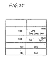
- a plurality of types of resources are incorporated into such a composite document in their respective unique file formats.
- a character file is incorporated in a text format, a HTML format, or a file format unique to an application used for preparing the file: a static image is incorporated into a composite document in a JPEG or GIF format; and a dynamic image is incorporated into a composite document in an MPEG format.
- An existing printer is provided with a mere renderer (i.e., a module for performing a rendering operation or preparing a print image of a document) corresponding to a certain printer control language.
- a mere renderer i.e., a module for performing a rendering operation or preparing a print image of a document
- the host computer interprets the file format of each resource contained in the composite document.
- the host computer converts document data into data expressed in a specific printer control language understandable to the printer and transfers the thus-converted print data to the printer.
- the printer interprets the data expressed in the specific printer control language and prepares and prints a print image of the document.
- an existing printer can understand only data expressed in a specific printer control language.
- the host computer In a case where data regarding a composite document are printed, the host computer must interpret various file formats contained in a composite document and convert the file formats into data described in the printer control language.
- the printer In the case of a network-compatible printer capable of being connected to a network such as the Internet, the printer has the function of following a network communications protocol such as TCP/IP. Accordingly, if the printer can interpret and print a composite document capable of being transferred according to the communications protocol, great convenience is afforded to the user.
- WO 96/01449 discloses a method and apparatus for printing a document over network. Specifically, WO 96/01449 provides a number of computer systems 70 and 72; printers 76 and 78; and a print server 82, which are connected together by a standard network bus 66. Printers 76 and 78 and a raster data front end 80 are also connected with the computer system 72 and the printer server 82 via a separate raster network bus. A further printer 122 is connected to the raster data front end 80. Printer 76, which is connected with both the standard and raster network buses, is provided with a raster image processor (RIP). This enables it to accept and process page description language (PDL) instructions.
- PDL page description language
- computer system 70 can generate PDL instructions and send them to printer 76 via standard network bus 66.
- Printer 76 can RIP these instructions and print the raster image (see page 8, lines 24 to 25).
- print server 82 may RIP received PDL instructions and then send the generated raster image to a selected printer, which need not be provided with a RIP function, via the raster network bus.
- Printers such as printer 78 that are not provided with an RIP function can only proces previouslyRiPed data provided by the raster network bus (see page 10, lines 3 to 6).
- the print servers 82, 168 in these figures do not include a print engine.
- the print server which acts as a local router, may itself be a network printer.
- an object of the present invention is to enable economic and convenient utilization of a plurality of printers which differ from one another in terms of language interpretation capability, a network communications function, and a rendering capability.
- Another object of the present invention is to provide an economic technique for enabling an underperforming printer to be used in the same manner as a high-performance printer.
- Yet another object of the present invention is to enable unified control of a plurality of printers capable of interpreting different languages through use of a single language.
- Still another object of the present invention is to enable a printer which cannot interpret a high-function language to be used in the same manner as a printer capable of interpreting a high-function language.
- a further object of the present invention is to enable free use of a plurality of printers through a simple and inexpensive scheme.
- a still further object of the present invention is to enable setting of a plurality of different types of printers through use of a single printer driver.
- Another object of the present invention is to enable devices which are difficult to solely connect to a network, e.g., one or more network-incompatible printer, to be connected to a network in a grouped manner.
- Still another object of the present invention is to enable incorporation of network-incompatible printers into a network through a simple and inexpensive scheme.
- Yet another object of the present invention is to provide a printer capable of receiving and printing a composite document containing a plurality of resources of various file formats or an environment substantially capable of realising such a printer.
- a network printer comprising:
- the network printer is adapted to convert the data to a language compatible with the network-incompatible device before performing the transfer operation to the network-incompatible device.
- the network-incompatible device is a printer.
- the network uses a TCP/IP protocol
- the network communications means has a plurality of IP addresses, a plurality of port numbers, or a plurality of identifiers as the plurality of network addresses and responds to a packet which is received from the network and includes any of the plurality of IP addresses, the port numbers, and the identifiers, and wherein the data transfer means selects a destination to which data included in the packet are transferred, according to the IP address, port number, or identifier of the packet including any of the plurality of IP addresses, the port numbers and the identifiers.
- the network printer is communicable with a host provided on the network, wherein:
- a computer-readable program recording medium having recorded thereon a computer program used when a computer implements a network printer as defined in any one of the preceding claims.
- the network printer performs all communications processing operations relative to the network as a proxy for another network-incompatible device, in relation to the network, and performs communications processing operations for the network printer itself relative to the network.
- Data are processed by the network printer or transferred to another network-incompatible device according to a communications address of the data.
- a network-incompatible device which cannot be solely connected to the network is connected to the network as a part of the group.
- the network printer is a single physical printer, it can act as a plurality of network-compatible devices assigned a plurality of network addresses.
- Figure 1 is a functional block diagram showing a print system according to a first embodiment of the present invention.
- a host computer e.g., a personal computer, transmits a print command written in (e.g., PostScript) in one predetermined high-function language.
- a high-function printer 2 is connected to the host computer 1.
- a low-function printer 3 is connected to this high-function printer 2.
- the high-function printer 2 has a rendering function of interpreting a print command which is received from the host computer 1 and which is written in a high-function language and of rendering an image to be printed; a print function of printing the thus-rendered image by itself; a transfer function of converting the thus-rendered image (although the image may be a final band or page image-in this case, an intermediate code of an intermediate code form in terms of a processing effciency) into a print command format written in a predetermined low-function language which can be interpreted by the low-function printer 3 and a selection function of automatically selecting one from the foregoing two functions (e.g., if the destination of the print command is the printer itself, the print function is selected.
- the transfer function is selected).
- the high-function printer 2 has a status reply function of notifying the host computer 1 of a printer status of the printer itself in the form of a status message written in a high-function language, and a proxy status reply function of receiving from the low-function printer 3 a message in which the printer status of the low-function printer 3 is written in a low-function language and of sending the message to the host computer 1 after converting the message into a status message of a high-function language.
- the low-function printer 3 cannot interpret a high-function language but interprets and prints a print command of a low-function language.
- the low-function printer 3 also has the status replay function of sending to the high-function printer 2 a message in which the printer status of the printer itself in a low-function language.
- the low-function language is inferior to the high-function language in terms cf expression capability.
- the low-function printer 3 which supports only such a low-function language is considerably cheaper than the high-function printer 2 supporting a high-function language.
- the high-function printer 2 Upon receipt of a print command written in a high-function language from the host computer 1, the high-function printer 2 interprets the thus-received print command. As a result of interpretation, the high-function printer 2 initially recognizes the destination of the print command and renders individual primitives (image elements: that is, individual characters, graphics, patterns, or an aggregate of these elements being spatially linked together) included in each page to be printed, thus preparing intermediate codes for each page. The thus-prepared intermediate codes are temporarily stored in RAM (not shown) of the high-function printer 2.
- the high-function printer 2 prepares a complete band image from the intermediate codes stored in the RAM and transfers the thus-prepared band image to a print engine (not shown) of the printer 2, thus printing an image.
- the high-function printer 2 incorporates the intermediate codes stored in the RAM into the format of a print command of a low-function language, thus preparing a low-function language print command.
- the thus-prepared low-function language print command is transferred to the low-function printer 3.
- the low-function printer 3 interprets the thus-received low-function language print command and renders a print image, thus printing the image.
- the high-function printer 2 In response to a request from the host computer 1 (or voluntarily), the high-function printer 2 sends to the host computer 1 the printer status of the printer 2 in the form of a status message written in the high-function language. Further, upon receipt of a status request addressed to the low-function printer 3 from the host computer 1, the high-function printer 2 sends the status request to the low-function printer 3 by converting the status request into a status request of a low-function language. In response to the status request (or voluntarily), the low-function printer 3 sends to the high-function printer 2 the printer status of the printer 3 in the form of a status message written in the low-function language.
- the high-function printer 2 extracts a printer status from the status message of the low-function language and prepares a status message of a high-function language by incorporation of the printer status received from the printer 3 into the format of a status message of a high-function language.
- the thus-prepared high-function message is transmitted to the host computer 1.
- the high-function printer 2 performs a printing operation by itself, it goes without saying that there is obtained a high-level print result deflecting a high expression capability of the high-function language. Further, even in a case where a printing operation is performed by means of the low-function printer 3, since the high-function printer 2 converts the high-function language into the low-function language, the host computer 1 enables control of the low-function printer 3 through use of only one high-function language, without being aware of what kind of language the low-function printer 3 can interpret. Further, since the high-function printer 2 renders an image on the basis of the high-function language, a high-level print result can be obtained without deteriorating the high expression capability of the high-function language.
- the host computer 1 can grasp the printer status of the high-function printer 2, as well as the printer status of the low-function printer 3 by means of the proxy status reply function of the high-function printer 2.
- the inexpensive low-function printer 3 can yield substantially the same performance as that of the high-function printer 2.
- a color ink-jet printer for example, is connected as the low-function printer 3 to the high-function printer 2.
- the high-function printer 2 prepares intermediate codes of respective color components from the color print command (the only requirement is to repeat a process of preparing a monochrome intermediate code for each color component plain). Further, the intermediate code may be converted into a print command of a low-function language, and the print command may be sent to the color ink-jet printer 3.
- the selection function of the high-function printer 2 responds not to the destination of the print command in the manner as mentioned previously, but to a determination as to whether the print command designate monochrome or color.
- the high-function printer 2 may be arranged so as to activate the selection function according to a load of the high-function printer 2 and that of the low-function printer 3 (e.g., if the high-function printer 2 is in the course of a printing operation and the low-function printer 3 is in a standby condition, the transfer function is activated, and in the case of the reverse situation, the print function is selected).
- the high-function printer 2 in place of the high-function printer 2, there may be used a processing device having the same functions as those of the high-function printer 2 exclusive of the print function.
- the high-function printer 2 acts as a "high-function printer” and a "proxy server” which interprets a high-function language as a proxy for the low-function printer 3, as well.
- the processing device acts solely as a "proxy server.”
- FIG. 2 is a functional block diagram showing a print system according to a second embodiment of the present invention.
- the high-function printer 2 is connected to a plurality of low-function printers 3A, 3B, ... through an internal communications network 5 such as an intranet within a company.
- the high-function printer 2 is connected to an external communications network 4, e.g., the Internet.
- the high-function printer 2 may be connected not only to the low-function printers 3A, 3B, ..., but also to another high-function printer.
- the high-function printer 2 receives a print command written in a high-function language such as PostScript from a host computer (not shown) provided on the external communications network 4 or the internal communications network 5. Upon receipt of the print command, the high-function printer 2 performs a printing operation (activates the print function) by itself on the basis of the received print command or selects one printer from the low-function printers 3A, 3B, ... and transmits the received print command of the high-function language to the thus-selected low-function printer after having converted the print command into a print command of a low-function language which can be interpreted by the selected low-function printer (i.e., activates the transfer function).
- a printing operation activates the print function
- the high-function printer 2 converts the high-function language print command into a print command of language A when the printer 3A is selected and converts the high-function language print command into a print command of language B when the printer 3B is selected.
- the high-function language print command is converted into language A or B in the same manner as in the first embodiment shown in Figure 1.
- the high-function printer 2 also has the status reply function and the proxy status reply function, both of which have been mentioned previously. Accordingly, upon receipt of a printer status message written in language A from the printer 3A, the high-function printer 2 converts the message into a printer status message of a high-function language and transmits the thus-converted message to the host computer. In contrast, upon receipt of a printer status message written in language B from the printer 3B, the high-function printer 2 converts the message into a printer status message of a high function language and transmits the thus-converted message to the host computer.
- the high-function printer 2 selects in step 302 a printer which is to perform a printing opetation.
- the printer which is to perform a printing operation is selected in the following manner. More specifically, in a case where a destination printer is selected by a print command, a designated printer is selected. If no printer is specified as a destination, a suitable printer is selected from printers remaining in a standby condition (e.g., a printer is selected from printers remaining in a standby condition in order of precedence or identification number. Alternatively, a printer is selected in decreasing order of frequency of accumulated use).
- the print command designates color printing
- a printer is inevitably selected from color printers.
- the print command designates monochrome printing
- an answer message such as a busy signal, is sent back to the sender of the print command.
- the high-function printer 2 determines whether or not the selected printer can interpret the high-function language (e.g., PostScript). If the printer can interpret the language (e.g., the high-function printer 2 itself or another high-function printer is selected), the processing proceeds to step 312. If the printer cannot interpret the language (e.g., the low-function printer 3A or 3B is selected), the processing proceeds to step 304. In a case where the processing proceeds to step 312, while receiving a subsequent print command from the communications network 4 the high-function printer 2 transmits the thus-received print command directly to the high-function printer in step 313. In a case where the high-function printer 2 is selected, the high-function printer 2 interprets the print command and generates an intermediate code. Further, the high-function printer 2 produces a band image from the intermediate code and prints the band image. After the operation has been performed through the end of the print command (step 314), the processing is completed.
- the high-function printer 2 e.g., PostScript.
- the high-function printer 2 checks which one of several predetermined low-function languages (e.g., languages A and B) corresponds to the language which can be interpreted by the selected printer. For example, in a case where the predetermined low-function language includes two types of languages, namely, language A and language B, if the result of such check corresponds to language A, the processing proceeds to step 305, and language A is determined to be the target language into which the print command is to be converted. In contrast, the result of such check does not correspond to language A, the processing proceeds to step 306, and language B is determined to be the target language into which the print command is to be converted.
- predetermined low-function languages e.g., languages A and B
- step 307 while receiving a subsequent print command, the high-function printer 2 interprets the thus-received print command and renders individual primitive raster images, thereby preparing an intermediate code.
- the thus-prepared intermediate code is temporarily stored in the RAM. In this way, an intermediate code corresponding to one page is prepared (step 308).
- step 309 the high-function printer 2 incorporates the intermediate code corresponding to one page into a print command format of the target low-function language determined in step 305 or 306, thereby preparing a print command of the low-function language.
- step 310 the high-function printer 2 transmits the thus-prepared print command of the low-function language to the selected printer.
- step 311 all the intermediate codes corresponding to one page are converted into a print command, and the print command is transmitted to the selected printer (step 311).
- the high-function printer 2 After having executed the processing defined in steps 307 to 311 through the end of the page (step 315), the high-function printer 2 completes the processing.
- the checking operation performed in step 304 can be carried out under a method such as that provided below.
- One method is to register beforehand languages compatible with the printers 3A, 3B, ... provided on the network 5 into the high-function printer 2 in the form of, e.g., a table, whereby a language is checked by reference to the thus-registered data.
- the high-function printer 2 may automatically register compatible languages by inquiring the printers 3A, 3B, ... about compatible languages. Alternatively, the languages may be manually registered by an operator by way of a keyboard.
- Another method of checking a language is to inquire a selected printer about a compatible language every time the high-function printer 2 receives a print command.
- the plurality of low-function printers 3A, 3B, ... can be controlled in a unified manner by means of a high-function language. Further, high-level printing operations reflecting a high expression capability of the high-function language can be carried out through use of the low-function printers 3A, 3B, ... Accordingly, a print system which is analogous, in terms of substantial function, to a print system comprising a plurality of high-function printers can be constructed considerably inexpensively through use of the plurality of low-function printers 3A, 3B,
- the high-function printer 2 may be replaced with a specifically-designed "proxy server" having no print function.
- one communications network 6 (or a plurality of small-scale networks linked together) comprises host computers 1A, 1B, ..., the high-function printer 2, and various low-function printers 3A, 3B, ...
- the high-function printer 2 receives a print command of a high-function language from the host computers 1A, 1B, ...
- the thus-received print command is converted into the languages that are compatible with the low-function printers, and the thus-converted languages can be transmitted to the low-function printers.
- an intermediate code is prepared from the received print command, and the intermediate code is converted into a command of the target language.
- the method is not necessarily required, and another method may alternatively be employed.
- a complete band or page raster image is prepared from the intermediate code, and the thus-prepared band or page image may be converted into a command of the target language.
- a look-up table for command conversion purpose or a command conversion function is prepared beforehand on the basis of the correspondence between languages and commands. The print command may be converted directly into a command of the target language through use of the table or the function.
- the latter method may deteriorate the expression capability of the high-function language, thus resulting in a reduction in picture quality.
- the method is suitable for a system according to a modification of the third embodiment, which will be described below, wherein a print command is converted into another language which is equivalent in expression capability to the language of the print command or into another language having a high expression capability.
- the ligh-function printer 2 may be replaced with a printer that is compatible with a specific language (e.g., a printer compatible with language A), to replace the low-function printers 3A, 3B, ... with printers compatible with other various languages, to cause the printer 2 compatible with language A, as a "proxy for another printer,” to receive a print command of language A and to transfer the thus-received print command to the printer after having converted the command into the language compatible with the printer.
- a specific language e.g., a printer compatible with language A
- a network printer 11 having a local router function connects itself to the Internet 12 and is capable of communicating with a host 15.
- the network printer 11 is connected to one or more network-incompatible printers 13, 14, ... which cannot connect themselves to the Internet, by way of respective interfaces which are connectable to the printers 13, 14, ...
- the network printer 11 has its own IP address and also serves as a printer. Accordingly, the network printer 11 can operate as one terminal printer provided on the Internet 12.
- the network printer 11 is also provided with IP addresses of the respective network-incompatible printers 13, 14, ... connected to the printer 11 and has the function of relaying communication between the printers 13, 14, ... and the host 15. Accordingly, the network printer 11 can also operate as a local router for the purpose of connecting the group of network-incompatible printers 13, 14, ... to the Internet 12.
- Figure 6 is a view for describing the relaying function of the network printer 11 shown in Figure 5 when it serves as a local router.
- the network printer 11 is connected to, e.g., an Ethernet 17 of an office LAN which is a part of the Internet 12.
- the network printer 11 has a protocol processing section comprising a physical layer 18 constituting a TCP/IP protocol stack for use in communication performed with the Internet 12, a data link layer 19, a network layer 20, a transport layer 21, and an application layer 22 (e.g., HTTP, FTP, SMTP, or LPR).
- a protocol processing section comprising a physical layer 18 constituting a TCP/IP protocol stack for use in communication performed with the Internet 12, a data link layer 19, a network layer 20, a transport layer 21, and an application layer 22 (e.g., HTTP, FTP, SMTP, or LPR).
- the network printer 11 has data interfaces such as a serial interface (S) 24, a parallel interface (P) 25, and a universal serial bus (USB) 26.
- the plurality of network-incompatible printers 13, 14, 16, ... can be connected to these data interfaces.
- the network printer 11 also has a protocol processing section comprising three protocol processing sections, that is, a protocol processing section comprising a physical layer 27 constituting a communications protocol stack for USB26 use, a data link layer 28, a network layer 29, a transport layer 30, and an application layer 31; a protocol processing section comprising a physical layer 32 constituting a data communications protocol stack for use with the serial interface 24, a data link layer 33, a network 34, a transport layer 35, and an application layer 36; and a protocol processing section comprising a physical layer 37 constituting a data communications protocol stack for use with the parallel interface 25, a data link layer 38, a network layer 39, a transport layer 40, and an application layer 41.
- each of the protocol stacks data are naturally transferred from a lower layer to an upper layer or from an upper layer to a lower layer.
- data are transferred between the network layer 20 in the TCP/IP protocol stack and the network layers 29, 34, and 39 of the other TCP/IP protocol stacks.
- the network-incompatible printers 13, 14, 16, ... can be connected to the Internet 12.
- FIG. 7 shows IP addresses of the network printer 11.
- the network printer 11 acquires IP addresses, e.g., "163,141,22,1" to "163,141,22,6" for four printers such as the printer 11 and the other printers 13, 14, and 16. These IP addresses are registered and retained in nonvolatile memory, such as NVRAM, in such a way that the four IP addresses correspond to destinations (e.g., the printer 11, the serial interface 24, the parallel interface 25, and the USB 26) assigned the respective IP addresses.
- destinations e.g., the printer 11, the serial interface 24, the parallel interface 25, and the USB 26
- the network printer 11 responds to all the received packets.
- the IP address of the received packet designates the printer 11
- the data contained in the packet are processed by means of the printer 11 itself.
- the IP address of the received packet designates another destination (S, P, and USB)
- the packet is transferred to a corresponding destination.
- a packet issued from the host 15 arrives at the network printer 11 by way of the Ethernet 17.
- the packet is initially converted from an electrical signal into a string of data bits by means of the physical layer 18 of the TCP/IP protocol stack.
- the thus-converted data bit stream is transferred to the data link layer 19.
- the data link layer 19 interprets a data link header DH provided in the header of the packet and checks a "MAC address" which is included in the data link header DH and represents destination hardware.
- the network printer 11 is assigned a unique, specific "MAC address" on the Internet 12, and the data link layer 19 is aware of this MAC address. If the MAC address of destination hardware included in a received packet matches a specific MAC address assigned to the network printer 11, the data link layer 19 deletes the data link head DH from the received packet and transfers the remaining portion of the packet to the network layer 20.
- the network layer 20 interprets the network header NH provided in the header of the packet received from the data link layer 19 and checks whether or not there is a match between the "IP address" which is included in the network header NH and represents a destination device and an "IP address" provided in an IP address list stored in the NVRAM such as that shown in Figure 7. As a result, if the IP address of the destination device included in the received packet matches the IP address assigned to the network printer 11, the network layer 20 removes the network header NH from the received packet and transfers the remaining portion of the packet to the transport layer 21.
- the network layer 20 of the TCP/IP stack transfers the received packet to the network layer 29, 34, or 39 of another protocol stack
- the network layer 20 converts the data format of the packet into a data format which can be handled by the destination network layer 29, 34, or 39.
- the specific details of the data format depends on actual specifications of the interfaces 24, 25, and 26. Since the data format is publicly known and is not directly relevant to the essence of the present invention, the data format will not be explained in the present specification. Further, the format or specifications of the data or packet used for the other network-incompatible interfaces 24, 25, and 26 is generally simpler than that used for the TCP/IP protocol.
- the transport layer 21 of the TCP/IP stack Upon receipt of the packet from the network layer 20, the transport layer 21 of the TCP/IP stack interprets a transport header TH included in the header of the packet and checks a "port number" which is included in the transport header TH and represents a destination application.
- the TCP/IP protocol system stipulates that a specific port number specify a specific application, e.g., port number 80 designating HTTP, and port number 31 designating FTP.
- the transport layer 21 is aware of the correspondence between port numbers and applications.
- the transport layer 21 removes the transport header TH from the received packet and transfers the remaining portion of the packet to an individual protocol (HTTP, FTP, SMTP, or LPR) of the application layer 22 specified by the port number.
- the individual protocol of the application layer 22 interprets an application header AH of the received packet and removes the application header AH from the packet, thus preparing net data.
- the thus-prepared net data are transferred to a processing routine (not shown) contained in the application which corresponds to an "identifier" included in the application header AH.
- the processing routine interprets the thus-received data (typically a print request, i.e., a print command) and performs a printing operation. In such a case, the network printer 11 performs a printing operation.
- the network layer 29, 34, or 39 of the protocol for another interface 26, 24, or 25 transfers the data to the data link layer 28, 33, or 38 of the protocol corresponding to the network.
- the data link layer 28, 33, or 38 transfers the received data to the physical layer 27, 32, or 37 of the protocol corresponding to the data link layer.
- the physical layer 27, 32, or 37 converts the data into an electrical signal and transmits the signal to the network-incompatible printer 16, 13, or 14 connected to the protocol stack corresponding to the physical layer. Accordingly, in such a case, the network-incompatible printer 16, 13, or 14 prints the data.
- Processing performed in each layer at the time of transfer of data from an upper layer to a lower layer within another protocol stack depends on actual specifications of the interface 24, 25, or 26. Such processing is publicly known and is irrelevant to the essence of the present invention. Therefore, the processing is not described herein. However, the processing performed in the protocol layer in the network-incompatible interface 24, 25, or 26 is generally simpler than that performed by the TCP/IP protocol (e.g., the network header is not distinguished from the data link header DH, or the network header NH and the data link header DH are omitted (i.e., they have a length of zero).
- the print request issued from the host 15 and received by the network printer 11 is printed by means of the network printer 11 according to the IP address of the destination included in the print request.
- the print request is transferred to the network printer 13, 14, or 16, where the print request is subjected to a printing operation.
- the data (e.g., a notification of printer status or error) output to the host 15 from the network printer 11 or from the network-incompatible printer 13, 14 or 16 are converted into a packet format of the Internet 12 addressed to the host 15 through a processing flow that is the reverse of that mentioned previously.
- the thus-converted packet format is sent to the Ethernet 17.
- the network layer 29, 34, or 39 of the network-incompatible interface protocol converts the format of the data into a packet format handled by the network layer 20 (i.e., into the same format as that of the packet transferred to the network layer 20 from the TCP/IP transport layer 21).
- any of the network-incompatible printers 13, 14, and 16 can be connected to the Internet 12.
- IP addresses are assigned different priorities within one network printer 11 having a plurality of IP addresses
- one physical network printer can be used as if there existed a plurality of printers having different functions, by changing a security level or a paper size according to a priority, selection of monochrome or color printing, selection of printing of an image or a text, or selection of ordinary printing or confidential printing which requires a password.
- the network printer itself is assigned one IP address
- a plurality of printers can be connected to the network through use of one IP address.
- a local router having only a relaying function such as that mentioned previously can be used in place of the network printers.
- IP address In addition to the IP address, another element, e.g., a port number or an identifier, may alternatively be used as the network address.
- a port number or an identifier For example, in the configuration shown in Figure 6, when a packet arrives at a network printer 22 from the Ethernet 17, the following protocol processing can be executed.
- print command data are transmitted twice to the network printer 11 by issue of two different transmission instructions to the operating system from the host 15.
- Figure 9 shows the foregoing processing.
- the print command data having a destination IP address of "163.141.22.51” are transmitted to a processing routine within the network printer 11.
- the print command data having a destination IP address of "163.141.22.52” or the print command data having a destination address of "163.141.22.53” are transferred to, e.g., the USB 26 and the network layer 29 and 34 of the serial interface, from the network layer 20 of TCP/IP, and are transferred to the network-incompatible printers 26, 24.
- the network-incompatible printers 26, 24 which are the destinations of the print command data are required to interpret the TCP/IP application layer protocols (LPR, HTTP, or FTP).
- LPR TCP/IP application layer protocols
- Print command data are transmitted twice to the network printer 11 by issue of two different transmission instructions from the host 15.
- FIG 10 shows the foregoing operations.
- the print command data assigned a destination port number "515" are transmitted to a processing routine within the network printer 11.
- the print command data assigned a destination port number "21" or "81" are transferred to, e.g., the USB 26 and the transport layers 30, 35 of the serial interface, from the transport layer 21 of TCP/IP, and are transferred to the network-incompatible printers 26, 24.
- the network-incompatible printers 26, 24 to which the print command data are transferred are required to interpret a TCP/IP application layer protocol (LPR, HTTP, or FTP).
- LPR TCP/IP application layer protocol
- print command data are transmitted twice to the network printer 11 by issue of two different transmission instructions from the host 15.
- Figure 11 shows the foregoing operations.
- the print command data having a destination print queue "PRINTER1" are transmitted to a processing routine within the network printer 11.
- the print command data having a destination print queue of "PRINTER2" and a destination print queue of "PRINTER3" are transferred to, e.g., the USB 26 and a TTY-procedure protocol of application layers 31, 36 of the serial interface, and are transferred to the network printers 26, 24.
- Figure 12 shows the configuration of a print system according to a fifth embodiment of the present invention.
- a network-compatible printer 51 has the function of connecting to a network, e.g., the Internet 55, and communicating with an arbitrary host 54 provided on the Internet 55, through use of a TCP/IP protocol. Further, the network-compatible printer 51 also connects a plurality of network-incompatible printers 52, 53, ... n, (as a matter of course, network-compatible printers are also usable) and communicates with these printers. For example, the network-compatible printer 51 has a connection port, e.g., a serial interface or a parallel interface. Throughout the present specification, the network-compatible printer 51 and the printers 52, 53, ... n connected to the printer 51 are collectively referred to as a printer group.
- printers close to the Internet 55 are referred to as upstream printers, and printers distant from the Internet 55 are referred to as downstream printers.
- Communication is established between the network-compatible printer 51 and the downstream network-incompatible printers 52, 53, ... n through use of the same protocol as a common protocol used in establishing connection between a host and a printer in a one-to-one relationship through a serial or parallel interface.
- the network-compatible printer 51 has the function of managing the downstream printers 52, 53, ... n and of connecting these printers to the Internet 55 (hereinafter referred to as a "printer management function").
- the printer management function has the following two processing functions.
- the first processing function is a function of examining the performance attributes of each of the downstream printers 52, 53, ... n and reporting the result of such examination to the host 54 (hereinafter referred to as “examination processing”).
- the second processing function is a function of transferring a print job received from the host 54 to a printer selected from the printer group (hereinafter referred to as "transfer processing").
- the transfer processing includes an operation for selecting a printer on the basis of the performance attributes of each printer (hereinafter referred to as a “determination operation"). The details of these processing and operations will be described later.
- Figure 13 is a flowchart regarding examination processing performed by the network-compatible printer.
- the network-compatible printer 51 inquires about the performance attributes of each printer, such as all setting items and the range of settings, from the downstream printers 52, 53, ... n and stores the thus-acquired information (1100).
- the term "setting item” used herein means predetermined items representing the type of attribute of the printer, e.g., a print color, a resolution, and a paper size.
- the term “range of settings” used herein means the range of values which can be set for each setting item. For example, in the case of a certain type of color printer, the range of settings implies monochrome or color for the print color, 300 or 600 dpi for the resolution, and letter, envelope, B5-size, or A4-size for the paper size.
- the network-compatible printer 51 determines whether or not all the downstream printers of the printer group are examined (1101). If there are still some unexamined printers, the network-compatible printer 51 continues examining the performance attributes of the printers. When all the printers have been examined, the network-compatible printer 51 sends to the host information including the performance attributes of all the printers of the printer group and the performance attributes of the network-compatible printer 51 (1103).
- the examination processing may be performed, e.g., when the network-compatible printer is first connected to the host 54 or when the host 54 requires the network-compatible printer to report the performance attributes of the printers.
- the examination processing may-be performed when the network-compatible printer 51 starts up or when any of the downstream printers 52, 53, ... n starts up after booting of the network-compatible printer 51.
- the result of such examination may be sent to the host 54 when the network-compatible printer is connected to the host 54 or when the host 54 requires the network-compatible printer 51 to report the performance attributes of the printers.
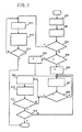
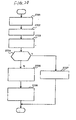
- Figure 14 is a flowchart regarding the transfer processing performed by the network-compatible printer 51.
- the network-compatible printer 51 Upon receipt of a print job from the host 54, the network-compatible printer 51 analyzes the contents of the print job and determines whether or not the performance attributes of the printer 51 enable performance attributes of the print job (1300). If the printer 51 can perform the print job, the printer 51 processes the data of the received job and performs a printing operation (1301).
- the printer 51 determines that the printer cannot perform print the print job because of incompatible performance attributes (or even when a sufficient resource for processing the currently-received job cannot be ensured, because the printer 51 is now processing another job)
- the printer 51 checks the performance attributes of any one of the downstream printers 52, 53, ... n within the printer group stored through examination processing (1302) and determines whether or not the received job can be received in light of the performance attributes of the thus-checked printer (1303). If the performance attributes of the print job is determined to be possible as a result of such check, the print job is transferred to the printer, where the print job is performed (1304).
- the performance attributes of the print job is impossible in light of the performance attributes of the printer (or because of insufficient resources)
- the performance attributes of the other downstream printers is checked one after another (1305). If a usable printer is found, the print job is transferred to the printer. If performance attributes of the print job is determined to be impossible even after checking all the printers within the printer group, the network-compatible printer 51 notifies the host 54 of the impossibility of performing the print job (1306).
- FIG 15 shows the details of the determination processing performed in steps 1300 and 1303 of the flowchart shown in Figure 14.
- the network-compatible printer 51 performs processing shown in Figure 15.
- the network-compatible printer 51 checks the details of the print job and acquires a printer attribute specified by the print job (1400).
- the network-compatible printer 51 determines whether or not a printer which is stored and is to be determined can support the setting value specified by the job (i.e., the setting value specified by the job is within the range of setting values of the setting items corresponding to the printer) by reference to the performance attributes of the printer to be determined (the printer 51 in step 1300 or a downstream printer to be determined in step 1303) (1401).
- the network-compatible printer 51 checks another setting value specified by the print job in the same manner (1402). If the printer can support all the setting values, the printer is determined to be able to print the print job (1403).
- the network-compatible printer 51 Through the foregoing processing operations performed by the network-compatible printer 51, all the printers included in the printer group can be connected to the Internet 55.
- the network-incompatible printers 52, 53, ... n provided downstream of the network-compatible printer 51 are in principle only required to perform in the same manner as when they are connected to the host 54 by way of a serial interface or a parallel interface.
- the network-compatible printer 51 appears to have the performance attributes of all the printers included in the printer group. Therefore, the host 54 is only required to handle the network-compatible printer 51. However, there is every possibility that the configuration of the printers within the printer group will be modified.
- the performance attributes of the network-compatible printer 51 also changes from the viewpoint of the host 54.
- a printer driver for use with the network-compatible printer 51 loaded in the host 54 is desirably to be able to flexibly cope with such a variation in the configuration of the printer group.
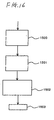
- Figure 16 shows one example of a processing flow of the flexible printer driver loaded into the host 54.
- the printer driver of the host 54 sends a performance attribute notification request to the furthest network-compatible printer 51 of the printer group (1500).
- the printer driver of the host 54 sends a performance attribute notification request to the furthest network-compatible printer 51 of the printer group (1500).
- the performance attributes of all the printers within the printer group are received from the network-compatible printer 51 (1501)
- the thus-received printer performance is stored, and a user interface screen including the performance attributes of all the printers are prepared and displayed (1502).
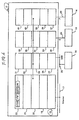
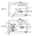
- Figure 17 shows examples of two types of user interface screens displayed in step 1502.
- the user interface screen comprises one or a plurality of setting windows 60 which are displayed in a superimposed manner.
- each setting window 60 there is (are) one or more than two setting item box(es) 61 representing a setting item.
- there are six setting windows 60 and one setting item box 61 is provided in the currently displayed setting window 60.
- there are six setting windows 60 and three setting item boxes 61 are provided in the currently displayed setting window 60.
- Below each setting item box 61 there are two or three or more setting value boxes 62 for indicating setting values. Radio buttons 63 for use in selecting a setting value are provided beside the respective setting value boxes 62.
- the printer driver has only information regarding a framework used for creating a user interface screen such as that shown in Figure 17.
- a framework used for creating a user interface screen such as that shown in Figure 17.
- the number of the setting windows 60 provided within the user interface screen, the number of the setting item boxes 61 provided in each of the setting windows 60, the number of setting value boxes 62 provided below each of the setting item boxes 61, and the details of each setting item box 61 and those of the setting value box 62 remain undetermined.
- the printer driver Upon receipt of the performance- attributes of all the printers included in the printer group in step 1501, the printer driver determines the number of setting windows 60, the number of setting item boxes 61 provided in each setting window 60, and the number of setting value boxes 62 provided below each setting item box 61 according to the number of setting items included in the performance attribute information and the number of setting values of each setting item.
- the title of each setting item included in the performance attribute information is entered into each setting item box 61, and a setting value of each setting item included in the performance attribute information is entered into each setting value box 62, thus preparing a user interface screen such as that shown in Figure 17.
- a setting item “PAINT” shown in Figure 17A indicates a print color
- a setting value "COLOR” indicates any of the printers in the printer group capable of producing a color print
- a setting item “MONO” indicates any of the printers in the printer group capable of producing a monochrome print.
- a setting item “RESOLUTION” shown in Figure 17B indicates a resolution, and setting values "600” and "300” provided below the setting item indicates that only two types of resolutions are selectively available.
- a setting item “PAPER SIZE” indicates a paper size, and setting values "A3,” “A4,” and “B4" indicate that only these three types of paper sizes are selectively available.
- a desired setting value can be selected by clicking the radio button 64 of the setting value through use of a mouse. Further, the radio button clicked by the mouse is filled with a black dot.
- the printer driver stores the thus-selected value as a specified printer attribute.
- the processing then proceeds to step 1503, and the printer driver waits for a print request from the user.
- the printer driver Upon receipt of a print request from the user, the printer driver converts the stored printer attribute and document data to be printed into print job data which can be interpreted by the network-compatible printer 51.
- the thus-converted print job data are transmitted to the network-compatible printer 51.
- the printer driver can flexibly cope with the performance attributes of the printer group.
- the network-compatible printer 51 Upon receipt of the foregoing request, the network-compatible printer 51 inquires about performance attributes of each of the downstream printers 52, 53, ... n. The inquiry request is also written into the same statement as is the performance attribute notification request.
- the following performance attribute information is sent back to the network-compatible printer 51 from each of the downstream printers 52, 53, ... n.
- EJL RANGE RESOLUTION 600/300 ⁇ LF>
- ANSWER a command code for performance attribute notification.
- the statement signifies a declarative statement representing notification of answers to all the setting items.
- a term "RANGE" is a command code signifying that the range of a setting value of the setting item is as follows .
- a parameter which follows "RANGE” and has a form of "title of setting item setting value 1/setting value 2/." signifies that setting values which can be selected for the setting item corresponding to the "title of setting item” are “Setting 1,” “Setting 2,” ...
- the network-compatible printer 51 Upon collecting the performance attribute information from all the downstream printers, the network-compatible printer 51 notifies the host 54 of the thus-collected performance attribute information.
- the performance attribute information has the same format as that mentioned previously.
- the RANGE statements received from the plurality of downstream printers may be sent to the host 54 while they are simply chained together in the order given, e.g., a RANGE statement described in the second and subsequent statements received from the first downstream printer, a RANGE statement described in the second and subsequent statements received from the second downstream printer, ...
- the notification statements received from the plurality of downstream printers may be arranged and edited to thus prepare the following new RANGE statement, and the thus-prepared new RANGE statement may be sent to the host.
- the printer driver of the host 54 Upon receipt of such performance attribute information, the printer driver of the host 54 extracts titles of setting items and setting values from parameters of each RANGE statement, thus preparing a user interface screen such as that illustrated in Figure 17.
- Print job data are sent to the network-compatible printer 51 from the host 54.
- the term "SET" is a command code signifying that there is specified an attribute represented by a parameter subsequent to SET. In this example, there are specified a resolution of 600 dpi, a monochrome print color, and A4-size paper.
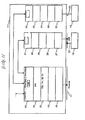
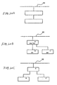
- Figure 18 shows the configuration of a print system according to a sixth embodiment of the present invention.
- a plurality of printers 70, 71, ... m may be daisy-chained to the furthest network-compatible printer 70 (in the form of a simple daisy chain formed by means of a bus or a cable) in a serial manner.
- a performance attribute notification request can be transmitted to all the downstream printers 71, ... m from the furthest upstream printer 70, and the performance attribute information can be collected to the furthest network-compatible printer 70 from all the downstream printers 71, ... m.
- the furthest network-compatible printer 70 have the function of managing the downstream printers in the manner identical with that mentioned in previous embodiments.
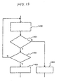
- the printers 70, 71, ... other than the furthest downstream printer “m” perform operations such as those shown in Figure 19 in order to report the performance attributes of the printer group to the host 54.
- each printer has only one adjacent downstream printer, and therefore the examination of performance attributes of an adjacent downstream printer is immediately completed.
- the printer performs the processing defined in step 1800 with respect to N adjacent downstream printers.
- each printer After the performance attributes of all downstream printers of the printer group have been checked in the foregoing manner, each printer notifies an adjacent upstream printer of the performance attributes of the adjacent downstream printer and those of subsequent downstream printers together with the performance attributes of the printer itself (1802).
- the information regarding the performance attributes of all the printers 71, ... m positioned downstream of the furthest upstream network-compatible printer 70 are collected to the furthest upstream network-compatible printer 70, and therefore the network-compatible printer 70 notifies the host 54 of the thus-gained performance attribute information together with the performance attributes of the printer 70 itself (1802).
- the network-compatible printer 70 determines whether to print the job data itself or to cause any of the downstream printer group to print the job data. In the latter case, the print job data are transferred to an adjacent downstream printer 71. Each printer makes an analogous determination. In a case where a printer of the downstream printer group is caused to print the job data, the print job data are transferred to an adjacent downstream printer. In this way, the print job data are relayed to the printer which is to finally print the print job data. During the course of relay of the print job data, each printer that has received the print job data determines whether the printer itself or any printer of the downstream printer group is suitable for processing the print job data. According to the result of determination of the printer, the printer which finally prints the print job data is determined in a so-called dynamic manner.
- the throughput of the print system can be increased by grouping printers of the same type.
- unique effects can be expected from combination of printers of different types as shown in Figures 20A to 20C.
- a monochrome laser printer is used in combination with a color ink-jet printer.
- a network-compatible printer function which includes a monochrome high-speed and high-resolution print function provided by the laser printer and a high-quality color print function provided by the color ink-jet printer, can be implemented at significantly less expense than can one network-compatible printer having an analogous function (i.e., a network-compatible color laser printer). So long as the print system is configured so as to be able to utilize a high-level language interpretation function and a rendering function, both of which are usually provided for a laser printer, there can be achieved higher throughput and a shorter host release time than can be achieved when solely an ink-jet printer is used.
- one large high-grade printer capable of producing an A3-size print and a plurality of inexpensive printers capable of producing solely A4-size or smaller-sized prints are grouped together.
- a high capacity print system capable of producing an A3-size print and a print of A4-sizer or smaller can be constituted at significantly less expense than can a print system comprising a plurality of large high-grade A3-size-capable printers.
- the A3-size-capable printer and the A4-size-capable printer are provided at the same address on the network, and therefore the print system is easier to use than is a print system having these printers at different addresses on the network.
- a high-function printer capable of rendering a high-function language having a considerably abundant expression capability, e.g., PostScript (Adobe Systems), and standard printers having no function of interpreting such a high-function language are grouped together.
- a high capability print system compatible with a high-function language can be constituted at significantly less expense than can a print system comprising a plurality of high-function printers.
- the standard printer can print an image which is equal in quality to an image produced by a high-function printer.
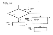
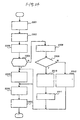
- Figure 21 shows the flow of processing for determining a printer which is to print a print job when there are two or more printers capable of supporting setting values specified by the job, in the previously-described two embodiments.
- a check is made as to whether or not there are two or more candidate printers capable of supporting the setting values specified by the job, by examination of the printer itself and all the printers provided downstream of the printer (1900). If there is only one candidate printer, a candidate print job is transferred to the candidate printer (1903). In contrast, if there are two or more candidate printers, the candidate printers satisfying any of the following conditions are eliminated one after another:
- the printer driver of the host is not necessarily required to be capable of such flexible response.
- the printer driver may also be configured such that setting items and values, which have already been fixed, are displayed on the user interface screen; such that the performance attributes of the printer group are not reported to the host from the network-compatible printer; such that only the network-compatible printer grasps the performance attributes of the printer group; and such that a printer which is to print a print job is selected according to the details of the job.
- the printer driver may also be configured such that the network-compatible printer does not notify the host of merely the performance attributes of the entire printer group but notifies the host of the identifiers of individual printers included in the printer group and their performance attributes; such that the user grasps the configuration of printers of the printer group and the performance attributes of each printer, by individually preparing and displaying a user interface screen corresponding to the performance attributes of each printer of the printer group; and such that a print request can be issued by designation of a desired printer.
- the printer driver issues print job data, there is specified which of the printers is caused to print a print job.
- the network-compatible printer can omit troublesome determination processing and can merely transfer the print job data to a specified printer.
- printer manager having only a network connection function and the foregoing function of managing the downstream printers.
- the network-compatible printer may be an originally network-compatible printer. However, there may also be employed a printer which become compatible with a network by attachment of an option, such as a network adapter, to an originally network-incompatible printer.
- the previously-mentioned downstream printer management function may be provided for a printer from the beginning. However, the function is not necessary for the printer.
- a network adapter may be provided with such a function, or the function may be provided for a printer in the form of add-on ROM or an additional board.
- a management function program may be loaded into a microcomputer incorporated in a printer, by way of a network or a host.
- Figure 22 is a block diagram showing a print system according to a seventh embodiment of the present invention.
- a printer 81 is connected to a local communications network 170 constituting a certain domain, such as an intranet or a LAN.
- the communications network 170 is also connected to other printers 101, 102 and host computers 103, 104. Further, the communications network 170 is connected to an external communications network 160, thus constituting a part of a large-scale network such as the Internet.
- Figure 23 shows the functional configuration of the printer 81 shown in Figure 22.
- the printer 81 has a communications interface 91, an imaging controller 92, and a print engine 93.
- the communications-interface 91 is connected to the communications network 170 and exchange data with respect to other devices provided on the networks 160, 170.
- the imaging controller 92 interprets the document data received by way of the communications interface 91 and prepares a print image of the document (i.e., binary raster image data representing whether or not a coloring dot is provided on each pixel position).
- the print engine 93 inputs the print image prepared by the imaging controller 92 and prints a document image on a sheet through use of a coloring agent and on the basis of the print image.
- the imaging controller 92 has a document analyzer 121, renderers 123A, 123B respectively corresponding to certain file formats A, B (e.g., HTML and JPEG), and an image composer 125.
- Figure 23 shows the renderers 123A, 123B corresponding to two file formats, these two renderers are mere examples. Renderers may be provided so as to correspond to a lesser or greater number of file formats.
- the entire imaging controller 92 can be implemented in the form of software by means of a microcomputer. Alternatively, at least part of the imaging controller 92 may be implemented through use of a specifically-designed hardware circuit.
- the document analyzer 121 analyzes the received document data and identifies the file format of the document data. If the document includes resources of predetermined file formats A, B, the resources are transferred to the renderers 123A, 123B corresponding to the file formats. In contrast, if the document includes a resource of a file format other than the file formats A, B (e.g., file format C), the resource of the file format C is transferred to a device having a renderer corresponding to the file format C among devices (the printers 101, 102 or the computers 103, 104) existing in an identical network domain (i.e., the network 170). The device is then requested to render the resource, and an image resulting from the rendering of the resource is received from the device.
- a resource of a file format other than the file formats A, B e.g., file format C
- the resource of the file format C is transferred to a device having a renderer corresponding to the file format C among devices (the printers 101, 102 or the computers 103, 104) existing
- the renderer 123A renders a resource of file format A (e.g., an HTML document), thus preparing a print image of the resource.
- the renderer 123B renders a resource of file format B (e.g., a JPEG image), thus preparing a print image of the resource.
- the renderers 123A, 123B usually divide one page of a document into a plurality of bands, thus preparing a print image for each band.
- the respective renderers prepare print images with regard to solely corresponding resources, and hence the print images are not complete print images of the composite document.
- the image composer 125 acquires the print images prepared by the renderers 123A, 123B for respective bands and the print images which another device prepares in response to a request. The thus-acquired print images are linked together, thus preparing a complete print image for each band.
- the print engine 93 receives one after another the complete print images prepared by the image composer 92 for each band and sequentially prints the individual band images on paper, thus preparing a hard copy of each page.
- the following description is based on the assumption that a certain host computer (e.g., a host computer 103) provided on the networks 160, 170 sends document data written in HTML to the printer 81.
- Other resources e.g., a JPG image and a GIFF image, are embedded in the HTML document data.
- Composite document data are constituted of the HTML document data and the other resources embedded in the HTML document data.
- the printer 81 performs operations such as those shown in Figure 24.
- the communications interface 91 receives the HTML document data and transfers the thus-received data to the imaging controller 92. Subsequently, in step 2302, the communications interface 91 receives other resources embedded in the received HTML document and transfer the resources to the imaging controller 92.
- the document analyzer 121 of the imaging controller 92 identifies the file format of each of the resources embedded in the received composite document.
- a decision is made as to whether or not the thus-identified file format can be rendered by the printer 81 (i.e., the thus-identified file format is format A or format B). If the printer 81 can render the file format, the processing proceeds to step 2305. If not, the processing proceeds to step 2308.
- the document analyzer 121 transfers the resource of file format A (or B) to the renderer 123A (or 123B).
- the renderer 123A (or 123B) renders the resources and prepares print data on a band basis, thus dearchiving the print data in memory (not shown).
- the document analyzer 121 retrieves a device having a renderer corresponding to the file format (e.g., file format C) which cannot be rendered by the printer 81, by reference to a device table such as that shown in Figure 25 which is registered in the printer 81 beforehand.
- a device table such as that shown in Figure 25 which is registered in the printer 81 beforehand.
- identifiers e.g., IP addresses
- the processing proceeds to step 2310. If not, the processing proceeds to step 2312.
- the document analyzer 121 transfers to the renderer 123B an image file, e.g., an image file of a certain picture (e.g., a frame picture), in place of the image of the resource. A print image of the image file is also prepared.
- the document analyzer 121 transmits the resource of file format C to the device selected from the device table, by way of the network 170, and requests the device to render the resource and to send back a result of such rendering. For example, in a case where the file format C is GIF, the GIF resource is sent to the printer 102 compatible with GIF.
- the printer 102 has a configuration analogous to that shown in Figure 22.
- the GIF resource requested by the printer 81 is rendered by means of a corresponding renderer, and a print image resulting from a rendering operation is sent back to the printer 81 by way of the network 170.
- the document analyzer 121 of the printer 81 receives the print image from the printer 102 and dearchives the print image into memory on a band basis.
- step 2306 The image composer 125 integrates the print images of the respective resources, thus dearchiving complete print data of each band on memory. Subsequently, in step 2307, the print engine 93 acquires the complete print image and prints the thus-acquired print image on paper.
- Figure 26 is a flowchart showing procedures required to register the device table shown in Figure 25 into the internal memory of the printer 81.
- the registration operation can be performed when the user orders the printer to perform, periodically, at the time of starting up of the printer, or at a suitable opportunity, whenever necessary.
- the document analyzer 121 of the printer 81 draws up a list of addresses of all the devices 101, 102, 103, and 104 provided within the domain by inquiring, e.g., a router having an identical routing table.
- the document analyzer 121 inquires of each of the thus-listed devices a file format which can be rendered by the device. If there is an answer to the inquiry from the device within a certain period of time, the document analyzer 121 proceeds to step 2504.
- the document analyzer 121 receives from the device a notification of the file format which can be rendered by the device.
- the file format is registered in the device table in such away as to correspond to the address of the device. An inquiry and registration are performed with regard to all the devices provided in the domain. As a result, a device table such as that shown in Figure 25 is completed.
- the printer 81 can receive and print a composite document including a plurality of file formats, by utilization of a renderer provided therein or a renderer of another device.
- the printer 81 sends to another device the resource of file format C which cannot be rendered by the printer 81 and requests the device to render the resource.
- another device has a converter capable of converting the file format C into a file format (e.g., format B) which can be rendered by the printer 81
- the printer 81 may request, in step 2310, the device not to render the resource but to convert the file format C of the resource to file format B.
- the printer 81 proceeds to step 2305 in a manner as indicated by a dotted arrow.
- the resource of file format B is rendered by means of the renderer 123B of the printer 81.
- an existing renderer which prepares a print image by interpretation of the data expressed in a specific printer control language.
- the printer requests another device to convert a file format in the manner as mentioned previously, the device may convert the file format into the data expressed in a specific printer control language (i.e., data having the same format as those received by an existing printer from the host), and the data may be rendered and printed by means of an existing renderer provided in the printer 81.
- Figure 27 is a block diagram showing an eighth embodiment of the present invention.
- a network 170 constituting a certain domain is connected to a printer 151 according to the present invention and other devices, e.g., printers 152, 153, and a host computer 154.
- the printer 151 is connected further to an external communications network 180.
- the printer 151 has such a configuration as that shown in Figure 22.
- the printer 151 has a function of retrieving a device capable of rendering the resource (or the foregoing converter) from the devices provided in the domain where the printer 151 itself is also provided.
- the printer 151 causes the thus-retrieved device to render or convert the resource and to transfer resultant data to the printer which is to print the data.
- the printer 151 has a device table which is analogous to that shown in Figure 25 and which shows the rendering capability of all the devices provided in the domain where the printer 151 itself is also provided. With such a function, a printer server having no printing function can be used in place of the printer 151.
- the printer 151 Upon receipt of composite document data from the communications network 180 in step 2701, the printer 151 selects, in step 2702, a printer (e.g., a printer 152)-which is to print the composite document-from the printers 151, 152, and 153 provided in the domain where the printer 151 itself is also provided, on the basis of a destination address included in the composite document data.
- a printer e.g., a printer 152
- the printer 151 checks the file format which can be rendered by the thus-selected printer 152, by reference to the pre-registered device table.
- the printer 152 determines whether or not all the resources included in the composite document can be rendered. As a result, if the resources can be rendered, the processing proceeds to step 2707. If not, the processing proceeds to step 2705.
- step 2707 the printer 151 transfers the composite document data to the selected printer 152.
- the printer 151 retrieves a device capable of rendering (or converting) a resource which cannot be rendered by the printer 152, by reference to the device table.
- the printer 151 transfers the resource to the thus-retrieved device and requests the device to render (or convert) the resource (if the printer 151 itself can render or convert the resource, the printer renders or converts the resource).
- the processing proceeds to step 2706, and the printer 151 transfers to the printer 152 a resource of the composite document data which can be rendered by the printer 152.
- a result of such rendering or conversion is also transferred to the printer 152 (a result of rendering or conversion performed by another device may be directly transferred to the printer 152 by bypassing the printer 151).
- the printer 152 can print the composite document in a complete form.
- a term “rendering” is explained as meaning preparation of a print image (i.e., a binary raster image used for driving a print engine).
- the term “rendering” is not limited to such a meaning.
- various forms of image data are prepared until a final print image is formed from a resource, e.g., an intermediate code, an RGB multivalued raster image, or a CMYK multivalued raster image.
- the renderer used when carrying out the present invention is not limited to any particular type of renderer, so long as it converts a resource of a composite document into image data of any form not dependent on a file format unique to the composite document.
- the format of image data output from the renderer assumes a tentative format such as the previously-described intermediate code, the RGB multivalued raster image, or the CMYK multivalued raster image. Accordingly, the rendering result obtained when the printer (or printer server) according to the present invention requests another device to render a certain resource is not necessarily required to correspond to a final print image.
- the rendering result may assume the format of an intermediate code or that of a multivalued raster image, so long as the result is image data which can be finally imaged in the form of a print by means of a printer (or printer server) which is to perform a printing operation.
- a term “convert” is used in addition to the term “rendering.”
- the term “convert” is used to represent conversion of a resource of a file format which cannot be interpreted by a printer of interest (or a print server of interest) into data of a format which can be interpreted by the printer.
- a term “rendering” used in claims should include not only the term “rendering” but also the term “convert” used in the previous embodiments.
Description
- The present invention generally relates to a digital printer and a technique for utilizing a printer, and more particularly, to a technique for realizing harmonious use of a plurality of printers which differ from one another in terms of a language interpretation capability, a network communications function, or a rendering capability, for using an underperforming printer in the same manner as a high-performance printer, or for causing a plurality of printers to complement to one another with regard to performance deficiencies.
- Various languages have been developed for use in describing print commands supplied to a printer from a host computer. Of these languages, some, such as a page description language "PostScript™" of Adobe Systems Incorporated in the U.S., have a very versatile expression capability and are capable of freely expressing complicated graphics which cannot be described by any other language. So long as such a high-function, high-level language is employed, complicated graphics can be printed beautifully at high speed. To this end, the printer must have a function of being able to interpret and render the high-function language. However, a printer capable of interpreting a high-function language such as PostScript is more expensive than a printer capable of interpreting solely a lower-function language. In a case where there are used a plurality of printers connected to a communications network, e.g., a LAN, if printers compatible with a high-function language are selected for all the printers, a very high cost will be incurred at the time of introduction of the printers.
- When a plurality of printers are connected to the network, the following problem will arise. More specifically, provided that a plurality of types of printers (e.g., page printers and serial printers) are connected to the network or that a plurality of printers produced by different manufacturers are connected to the network, the language that can be interpreted differs from printer to printer. For this reason, the user of the host computer is required to determine beforehand a printer which he desires to use and to select a language (in effect, a printer driver) suitable for the printer. However, so long as print quality is guaranteed, use of any printer poses no problems for the user. Accordingly, it is convenient for the user to utilize various printers under a unified method without consideration of the type of printer or printer driver.
- In an existing communications network, e.g., the Internet, one terminal is usually assigned one IP address. Communication between network-compatible terminals, each of which has an IP address and a TCP/IP execution function, form the basis of the network.
- For example, in a case where all the printers disposed in an office are to be connected to the Internet, there are many types of existing printers which cannot be directly connected to the Internet, and hence an expensive network adapter must be attached to each of these printers, resulting in a considerably large economic burden. Further, there are many types of existing printers incapable of operating with the network.
- The foregoing problem may be expressed in terms of a more general problem: that is, a plurality of terminals including both network-incompatible terminals and network-compatible terminals are collected into one group (e.g., all the printers disposed in an office are collected into one group), and no existing means provides a relay function capable of connecting the entire group to a network.
- With regard to a relay function related to the network, in an existing line there is provided a router which performs a relaying operation called a routing operation (e.g., selection of a communications path, data exchange between adjacent networks, and management of IP addresses of the network) for routing data transferred over the Internet to a desired terminal. However, since the router is intended to relay data between domains within the Internet, the router cannot serve as means for solving the problem, i.e., means for connecting to a network a group including network-incompatible terminals such as those mentioned previously.
- A document-which is supplied via WWW service over the Internet and which is written in , e.g., HTML, -is a composite document comprising text characters and another type of resource, such as audio, a dynamic image, or a static image, embedded into the text characters. A plurality of types of resources are incorporated into such a composite document in their respective unique file formats. For example, a character file is incorporated in a text format, a HTML format, or a file format unique to an application used for preparing the file: a static image is incorporated into a composite document in a JPEG or GIF format; and a dynamic image is incorporated into a composite document in an MPEG format.
- An existing printer is provided with a mere renderer (i.e., a module for performing a rendering operation or preparing a print image of a document) corresponding to a certain printer control language. In an existing print system comprising an existing printer connected to a host computer, when a composite document such as that mentioned previously is printed, the host computer interprets the file format of each resource contained in the composite document. The host computer converts document data into data expressed in a specific printer control language understandable to the printer and transfers the thus-converted print data to the printer. The printer interprets the data expressed in the specific printer control language and prepares and prints a print image of the document.
- As mentioned above, an existing printer can understand only data expressed in a specific printer control language. In a case where data regarding a composite document are printed, the host computer must interpret various file formats contained in a composite document and convert the file formats into data described in the printer control language. However, in the case of a network-compatible printer capable of being connected to a network such as the Internet, the printer has the function of following a network communications protocol such as TCP/IP. Accordingly, if the printer can interpret and print a composite document capable of being transferred according to the communications protocol, great convenience is afforded to the user.
- WO 96/01449 discloses a method and apparatus for printing a document over network. Specifically, WO 96/01449 provides a number of
computer systems 70 and 72; printers 76 and 78; and a print server 82, which are connected together by a standard network bus 66. Printers 76 and 78 and a raster data front end 80 are also connected with the computer system 72 and the printer server 82 via a separate raster network bus. A further printer 122 is connected to the raster data front end 80. Printer 76, which is connected with both the standard and raster network buses, is provided with a raster image processor (RIP). This enables it to accept and process page description language (PDL) instructions. Thus,computer system 70 can generate PDL instructions and send them to printer 76 via standard network bus 66. Printer 76 can RIP these instructions and print the raster image (see page 8,lines 24 to 25). Alternatively, print server 82 may RIP received PDL instructions and then send the generated raster image to a selected printer, which need not be provided with a RIP function, via the raster network bus. Printers such as printer 78 that are not provided with an RIP function can only proces previouslyRiPed data provided by the raster network bus (see page 10,lines 3 to 6). - However, unlike printers 76, 78 and 122 in Figure 4, and
printers 158, 160 and 164 in Figure 5, the print servers 82, 168 in these figures do not include a print engine. Thus, there is no disclosure in WO 96/01449 that the print server, which acts as a local router, may itself be a network printer. - Accordingly, an object of the present invention is to enable economic and convenient utilization of a plurality of printers which differ from one another in terms of language interpretation capability, a network communications function, and a rendering capability.
- Another object of the present invention is to provide an economic technique for enabling an underperforming printer to be used in the same manner as a high-performance printer.
- Yet another object of the present invention is to enable unified control of a plurality of printers capable of interpreting different languages through use of a single language.
- Still another object of the present invention is to enable a printer which cannot interpret a high-function language to be used in the same manner as a printer capable of interpreting a high-function language.
- A further object of the present invention is to enable free use of a plurality of printers through a simple and inexpensive scheme.
- A still further object of the present invention is to enable setting of a plurality of different types of printers through use of a single printer driver.
- Another object of the present invention is to enable devices which are difficult to solely connect to a network, e.g., one or more network-incompatible printer, to be connected to a network in a grouped manner.
- Still another object of the present invention is to enable incorporation of network-incompatible printers into a network through a simple and inexpensive scheme.
- Yet another object of the present invention is to provide a printer capable of receiving and printing a composite document containing a plurality of resources of various file formats or an environment substantially capable of realising such a printer.
- According to the present invention, there is provided a network printer comprising:
- network communications means which can connect to a communications network, has a plurality of network addresses representing a plurality of locations on the network, and responds to a communications message that is received by the network printer from the communications network and is addressed to any of the plurality of network addresses;
- data transfer means which can transfer the data included in the communications message to a plurality of destinations and selects destinations of the data according to the network address of the communication message; and
- connection means for connecting the printer to a network-incompatible device as at least one of the plurality of destinations, wherein when the communications message is a print command and the selected destination of the data is the network printer, the network printer is adapted to perform a print operation; and
-
- Preferably, the network printer is adapted to convert the data to a language compatible with the network-incompatible device before performing the transfer operation to the network-incompatible device.
- Preferably, the network-incompatible device is a printer.
- Preferably, the network uses a TCP/IP protocol, and the network communications means has a plurality of IP addresses, a plurality of port numbers, or a plurality of identifiers as the plurality of network addresses and responds to a packet which is received from the network and includes any of the plurality of IP addresses, the port numbers, and the identifiers, and wherein the data transfer means selects a destination to which data included in the packet are transferred, according to the IP address, port number, or identifier of the packet including any of the plurality of IP addresses, the port numbers and the identifiers.
- Preferably, the network printer is communicable with a host provided on the network, wherein:
- the data transfer means has all the network addresses assigned to a device group including the network printer and the devices, and relays communication between the host and the plurality of devices pertaining to the device group, in response to communication which is sent from the host.
-
- According to another aspect of the present invention, there is provided a computer-readable program recording medium having recorded thereon a computer program used when a computer implements a network printer as defined in any one of the preceding claims.
- With regard to the network printer defined above, so long as another network-incompatible device (e.g. a printer) is connected to the network printer, the network printer performs all communications processing operations relative to the network as a proxy for another network-incompatible device, in relation to the network, and performs communications processing operations for the network printer itself relative to the network. Data are processed by the network printer or transferred to another network-incompatible device according to a communications address of the data. Accordingly, in addition to the network printer, a network-incompatible device which cannot be solely connected to the network is connected to the network as a part of the group. Although the network printer is a single physical printer, it can act as a plurality of network-compatible devices assigned a plurality of network addresses.
-
- Figure 1 is a functional block diagram showing a print system according to a first embodiment of the present invention.
- Figure 2 is a functional block diagram showing a print system according to a second embodiment of the present invention.
- Figure 3 is a flowchart showing the operation of the print system according to the second embodiment.
- Figure 4 is a functional block diagram showing a print system according toa third embodiment of the present invention.
- Figure 5 is a diagrammatic representation showing a communications network which uses a network printer having a local router function according to a fourth embodiment of the present invention:
- Figure 6 is a view for describing the relaying function of the network printer shown in Figure 5 when it serves as a local router:
- Figure 7 shows IP addresses of the network printer:
- Figure 8 shows an example in which, since there is a match between the IP address included in the received packet and the IP address of the USB, the received packet is transferred to the network layer of the protocol stack for the USB:
- Figure 9 shows the processing in the printer:
- Figure 10 shows the operations in the printer:
- Figure 11 shows the operations in the printer:
- Figure 12 shows the configuration of a print system according to a fifth embodiment of the present invention:
- Figure 13 is a flowchart regarding examination processing performed by the network-compatible printer:
- Figure 14 is a flowchart regarding the transfer processing performed by the network-compatible printer:
- Figure 15 shows the details of the determination processing performed in
steps - Figure 16 shows one example of a processing flow of the flexible printer driver loaded into the host:
- Figures 17A and 17B show examples of two types of user interface screens displayed in step 1502:
- Figure 18 shows the configuration of a print system according to a sixth embodiment of the present invention:
- Figure 19 is a flowchart of the processing of the print system shown in Fig. 18:
- Figure 20A is a schematic diagram of the print system with a monochrome laser printer is used in combination with a color ink-jet printer, Figure 20B is a diagram showing an example of the system with different types of printers, and Figure 20C is a diagram showing another example of the system:
- Figure 21 shows the flow of processing for determining a printer which is to print a print job when there are two or more printers capable of supporting setting values specified by the job, in the previously-described two embodiments:
- Figure 22 is a block diagram showing a print system according to a seventh embodiment of the present invention:
- Figure 23 shows the functional configuration of the printer shown in Figure 22:
- Figure 24 is a flowchart showing the operations performed by the printer 81:
- Figure 25 is a device table which is registered in the
printer 81 beforehand: - Figure 26 is a flowchart showing procedures required to register the device table shown in Figure 25 into the internal memory of the printer:
- Figure 27 is a block diagram showing an eighth embodiment of the present invention; and
- Figure 28 is a flowchart showing the operation of the
printer 151. -
- Figure 1 is a functional block diagram showing a print system according to a first embodiment of the present invention.
- A
host computer 1, e.g., a personal computer, transmits a print command written in (e.g., PostScript) in one predetermined high-function language. A high-function printer 2 is connected to thehost computer 1. A low-function printer 3 is connected to this high-function printer 2. - The high-
function printer 2 has a rendering function of interpreting a print command which is received from thehost computer 1 and which is written in a high-function language and of rendering an image to be printed; a print function of printing the thus-rendered image by itself; a transfer function of converting the thus-rendered image (although the image may be a final band or page image-in this case, an intermediate code of an intermediate code form in terms of a processing effciency) into a print command format written in a predetermined low-function language which can be interpreted by the low-function printer 3 and a selection function of automatically selecting one from the foregoing two functions (e.g., if the destination of the print command is the printer itself, the print function is selected. In contrast, if the destination is the low-function printer 3, the transfer function is selected). Further, the high-function printer 2 has a status reply function of notifying thehost computer 1 of a printer status of the printer itself in the form of a status message written in a high-function language, and a proxy status reply function of receiving from the low-function printer 3 a message in which the printer status of the low-function printer 3 is written in a low-function language and of sending the message to thehost computer 1 after converting the message into a status message of a high-function language. - The low-
function printer 3 cannot interpret a high-function language but interprets and prints a print command of a low-function language. The low-function printer 3 also has the status replay function of sending to the high-function printer 2 a message in which the printer status of the printer itself in a low-function language. The low-function language is inferior to the high-function language in terms cf expression capability. Usually, the low-function printer 3 which supports only such a low-function language is considerably cheaper than the high-function printer 2 supporting a high-function language. - The operation of the print system according to the first embodiment will now be described. Upon receipt of a print command written in a high-function language from the
host computer 1, the high-function printer 2 interprets the thus-received print command. As a result of interpretation, the high-function printer 2 initially recognizes the destination of the print command and renders individual primitives (image elements: that is, individual characters, graphics, patterns, or an aggregate of these elements being spatially linked together) included in each page to be printed, thus preparing intermediate codes for each page. The thus-prepared intermediate codes are temporarily stored in RAM (not shown) of the high-function printer 2. In a case where the destination of the print command is the high-function printer 2, the high-function printer 2 prepares a complete band image from the intermediate codes stored in the RAM and transfers the thus-prepared band image to a print engine (not shown) of theprinter 2, thus printing an image. In contrast, in a case where the destination of the print command is the low-function printer 3, the high-function printer 2 incorporates the intermediate codes stored in the RAM into the format of a print command of a low-function language, thus preparing a low-function language print command. The thus-prepared low-function language print command is transferred to the low-function printer 3. The low-function printer 3 interprets the thus-received low-function language print command and renders a print image, thus printing the image. - In response to a request from the host computer 1 (or voluntarily), the high-
function printer 2 sends to thehost computer 1 the printer status of theprinter 2 in the form of a status message written in the high-function language. Further, upon receipt of a status request addressed to the low-function printer 3 from thehost computer 1, the high-function printer 2 sends the status request to the low-function printer 3 by converting the status request into a status request of a low-function language. In response to the status request (or voluntarily), the low-function printer 3 sends to the high-function printer 2 the printer status of theprinter 3 in the form of a status message written in the low-function language. The high-function printer 2 extracts a printer status from the status message of the low-function language and prepares a status message of a high-function language by incorporation of the printer status received from theprinter 3 into the format of a status message of a high-function language. The thus-prepared high-function message is transmitted to thehost computer 1. - In a case where the high-
function printer 2 performs a printing operation by itself, it goes without saying that there is obtained a high-level print result deflecting a high expression capability of the high-function language. Further, even in a case where a printing operation is performed by means of the low-function printer 3, since the high-function printer 2 converts the high-function language into the low-function language, thehost computer 1 enables control of the low-function printer 3 through use of only one high-function language, without being aware of what kind of language the low-function printer 3 can interpret. Further, since the high-function printer 2 renders an image on the basis of the high-function language, a high-level print result can be obtained without deteriorating the high expression capability of the high-function language. Thehost computer 1 can grasp the printer status of the high-function printer 2, as well as the printer status of the low-function printer 3 by means of the proxy status reply function of the high-function printer 2. In short, the inexpensive low-function printer 3 can yield substantially the same performance as that of the high-function printer 2. - In the case of one modification of the first embodiment: namely, in a case where the high-
function printer 2 is, e.g., a laser monochrome printer, a color ink-jet printer, for example, is connected as the low-function printer 3 to the high-function printer 2. If a color print command written in the high-function language is input to the high-function printer 2, the high-function printer 2 prepares intermediate codes of respective color components from the color print command (the only requirement is to repeat a process of preparing a monochrome intermediate code for each color component plain). Further, the intermediate code may be converted into a print command of a low-function language, and the print command may be sent to the color ink-jet printer 3. As a result, there can be effected high-level color printing reflecting a high-function language, which conventionally would be implemented through use of only a high-function color printer (which is considerably expensive at the present time), by means of a low-cost configuration comprising a high-function monochrome printer and a low-function color printer. In such a case, the selection function of the high-function printer 2 responds not to the destination of the print command in the manner as mentioned previously, but to a determination as to whether the print command designate monochrome or color. - In another modification of the first embodiment, the high-
function printer 2 may be arranged so as to activate the selection function according to a load of the high-function printer 2 and that of the low-function printer 3 (e.g., if the high-function printer 2 is in the course of a printing operation and the low-function printer 3 is in a standby condition, the transfer function is activated, and in the case of the reverse situation, the print function is selected). - In still another modification, in place of the high-
function printer 2, there may be used a processing device having the same functions as those of the high-function printer 2 exclusive of the print function. In short, in the present embodiment, the high-function printer 2 acts as a "high-function printer" and a "proxy server" which interprets a high-function language as a proxy for the low-function printer 3, as well. However, in the modification, the processing device acts solely as a "proxy server." - Figure 2 is a functional block diagram showing a print system according to a second embodiment of the present invention. -For example, the high-
function printer 2 is connected to a plurality of low-function printers internal communications network 5 such as an intranet within a company. Further, the high-function printer 2 is connected to anexternal communications network 4, e.g., the Internet. Although not shown in the drawing, it goes without saying that the high-function printer 2 may be connected not only to the low-function printers - The high-
function printer 2 receives a print command written in a high-function language such as PostScript from a host computer (not shown) provided on theexternal communications network 4 or theinternal communications network 5. Upon receipt of the print command, the high-function printer 2 performs a printing operation (activates the print function) by itself on the basis of the received print command or selects one printer from the low-function printers function printer 3A responds to, e.g., language A, and the low-function printer 3B responds to, e.g., language B, the high-function printer 2 converts the high-function language print command into a print command of language A when theprinter 3A is selected and converts the high-function language print command into a print command of language B when theprinter 3B is selected. The high-function language print command is converted into language A or B in the same manner as in the first embodiment shown in Figure 1. - The high-
function printer 2 also has the status reply function and the proxy status reply function, both of which have been mentioned previously. Accordingly, upon receipt of a printer status message written in language A from theprinter 3A, the high-function printer 2 converts the message into a printer status message of a high-function language and transmits the thus-converted message to the host computer. In contrast, upon receipt of a printer status message written in language B from theprinter 3B, the high-function printer 2 converts the message into a printer status message of a high function language and transmits the thus-converted message to the host computer. - The operation of the print system according to the second embodiment will now be described with reference to a flowchart shown in Figure 3. When receiving a print request from the
communications network 4 instep 301, the high-function printer 2 selects in step 302 a printer which is to perform a printing opetation. For example, the printer which is to perform a printing operation is selected in the following manner. More specifically, in a case where a destination printer is selected by a print command, a designated printer is selected. If no printer is specified as a destination, a suitable printer is selected from printers remaining in a standby condition (e.g., a printer is selected from printers remaining in a standby condition in order of precedence or identification number. Alternatively, a printer is selected in decreasing order of frequency of accumulated use). If the print command designates color printing, a printer is inevitably selected from color printers. In contrast, if the print command designates monochrome printing, as often as possible a printer is selected from monochrome printers. If no printers are in a standby condition, an answer message, such as a busy signal, is sent back to the sender of the print command. - In
step 303, the high-function printer 2 determines whether or not the selected printer can interpret the high-function language (e.g., PostScript). If the printer can interpret the language (e.g., the high-function printer 2 itself or another high-function printer is selected), the processing proceeds to step 312. If the printer cannot interpret the language (e.g., the low-function printer communications network 4 the high-function printer 2 transmits the thus-received print command directly to the high-function printer instep 313. In a case where the high-function printer 2 is selected, the high-function printer 2 interprets the print command and generates an intermediate code. Further, the high-function printer 2 produces a band image from the intermediate code and prints the band image. After the operation has been performed through the end of the print command (step 314), the processing is completed. - In contrast, in a case where the processing proceeds to step 304, the high-
function printer 2 checks which one of several predetermined low-function languages (e.g., languages A and B) corresponds to the language which can be interpreted by the selected printer. For example, in a case where the predetermined low-function language includes two types of languages, namely, language A and language B, if the result of such check corresponds to language A, the processing proceeds to step 305, and language A is determined to be the target language into which the print command is to be converted. In contrast, the result of such check does not correspond to language A, the processing proceeds to step 306, and language B is determined to be the target language into which the print command is to be converted. - In
step 307, while receiving a subsequent print command, the high-function printer 2 interprets the thus-received print command and renders individual primitive raster images, thereby preparing an intermediate code. The thus-prepared intermediate code is temporarily stored in the RAM. In this way, an intermediate code corresponding to one page is prepared (step 308). Next, instep 309, the high-function printer 2 incorporates the intermediate code corresponding to one page into a print command format of the target low-function language determined instep step 310, the high-function printer 2 transmits the thus-prepared print command of the low-function language to the selected printer. As mentioned above, all the intermediate codes corresponding to one page are converted into a print command, and the print command is transmitted to the selected printer (step 311). After having executed the processing defined insteps 307 to 311 through the end of the page (step 315), the high-function printer 2 completes the processing. - The checking operation performed in
step 304 can be carried out under a method such as that provided below. One method is to register beforehand languages compatible with theprinters network 5 into the high-function printer 2 in the form of, e.g., a table, whereby a language is checked by reference to the thus-registered data. The high-function printer 2 may automatically register compatible languages by inquiring theprinters function printer 2 receives a print command. Even in this case, so long as the language checked through inquiry is registered in a table provided within the high-function printer 2 so as to correspond to the printer, if the same printer is selected in subsequent operations a compatible language can be determined by merely referring to the registered data without inquiry. - According to the second embodiment, the plurality of low-
function printers function printers function printers - Even in the second embodiment, the high-
function printer 2 may be replaced with a specifically-designed "proxy server" having no print function. - As shown in Figure 4, according to a third embodiment, one communications network 6 (or a plurality of small-scale networks linked together) comprises
host computers 1A, 1B, ..., the high-function printer 2, and various low-function printers function printers function printer 2 receives a print command of a high-function language from thehost computers 1A, 1B, ... The thus-received print command is converted into the languages that are compatible with the low-function printers, and the thus-converted languages can be transmitted to the low-function printers. - In the previous embodiment, when the received print command is converted into the language compatible with the selected printer, an intermediate code is prepared from the received print command, and the intermediate code is converted into a command of the target language. However, the method is not necessarily required, and another method may alternatively be employed. For example, a complete band or page raster image is prepared from the intermediate code, and the thus-prepared band or page image may be converted into a command of the target language. Alternatively, a look-up table for command conversion purpose or a command conversion function is prepared beforehand on the basis of the correspondence between languages and commands. The print command may be converted directly into a command of the target language through use of the table or the function. In a case where a command of a high-function language is converted into a command of a low-function language, the latter method may deteriorate the expression capability of the high-function language, thus resulting in a reduction in picture quality. However, the method is suitable for a system according to a modification of the third embodiment, which will be described below, wherein a print command is converted into another language which is equivalent in expression capability to the language of the print command or into another language having a high expression capability.
- Further, in each of the embodiments shown in Figures 1 through 4, the ligh-
function printer 2 may be replaced with a printer that is compatible with a specific language (e.g., a printer compatible with language A), to replace the low-function printers printer 2 compatible with language A, as a "proxy for another printer," to receive a print command of language A and to transfer the thus-received print command to the printer after having converted the command into the language compatible with the printer. In such a system, even when there exist various types of printers manufactured by various manufacturers, these printers can be controlled in a unified manner through use of one language such as ESC/Page. Figure 5 is a diagrammatic representation showing a communications network which uses a network printer having a local router function according to a fourth embodiment of the present invention. - In Figure 5, a
network printer 11 having a local router function connects itself to theInternet 12 and is capable of communicating with ahost 15. Thenetwork printer 11 is connected to one or more network-incompatible printers printers network printer 11 has its own IP address and also serves as a printer. Accordingly, thenetwork printer 11 can operate as one terminal printer provided on theInternet 12. In addition, thenetwork printer 11 is also provided with IP addresses of the respective network-incompatible printers printer 11 and has the function of relaying communication between theprinters host 15. Accordingly, thenetwork printer 11 can also operate as a local router for the purpose of connecting the group of network-incompatible printers Internet 12. - Figure 6 is a view for describing the relaying function of the
network printer 11 shown in Figure 5 when it serves as a local router. - The
network printer 11 is connected to, e.g., anEthernet 17 of an office LAN which is a part of theInternet 12. Thenetwork printer 11 has a protocol processing section comprising aphysical layer 18 constituting a TCP/IP protocol stack for use in communication performed with theInternet 12, adata link layer 19, anetwork layer 20, atransport layer 21, and an application layer 22 (e.g., HTTP, FTP, SMTP, or LPR). - The
network printer 11 has data interfaces such as a serial interface (S) 24, a parallel interface (P) 25, and a universal serial bus (USB) 26. The plurality of network-incompatible printers network printer 11 also has a protocol processing section comprising three protocol processing sections, that is, a protocol processing section comprising aphysical layer 27 constituting a communications protocol stack for USB26 use, adata link layer 28, anetwork layer 29, atransport layer 30, and anapplication layer 31; a protocol processing section comprising aphysical layer 32 constituting a data communications protocol stack for use with theserial interface 24, adata link layer 33, anetwork 34, atransport layer 35, and anapplication layer 36; and a protocol processing section comprising aphysical layer 37 constituting a data communications protocol stack for use with theparallel interface 25, adata link layer 38, anetwork layer 39, atransport layer 40, and anapplication layer 41. - In each of the protocol stacks, data are naturally transferred from a lower layer to an upper layer or from an upper layer to a lower layer. In addition, as will be described in detail, data are transferred between the
network layer 20 in the TCP/IP protocol stack and the network layers 29, 34, and 39 of the other TCP/IP protocol stacks. As a result, the network-incompatible printers Internet 12. - Figure 7 shows IP addresses of the
network printer 11. As shown in Figure 7, thenetwork printer 11 acquires IP addresses, e.g., "163,141,22,1" to "163,141,22,6" for four printers such as theprinter 11 and theother printers printer 11, theserial interface 24, theparallel interface 25, and the USB 26) assigned the respective IP addresses. When there is received from the Internet 12 a packet including any of the four IP addresses, thenetwork printer 11 responds to all the received packets. As will be described later, if the IP address of the received packet designates theprinter 11, the data contained in the packet are processed by means of theprinter 11 itself. In contrast, if the IP address of the received packet designates another destination (S, P, and USB), the packet is transferred to a corresponding destination. - Such processing will be performed by means of a configuration shown in Figure 6.
- A packet issued from the
host 15 arrives at thenetwork printer 11 by way of theEthernet 17. As shown in Figure 8, the packet is initially converted from an electrical signal into a string of data bits by means of thephysical layer 18 of the TCP/IP protocol stack. The thus-converted data bit stream is transferred to thedata link layer 19. Thedata link layer 19 interprets a data link header DH provided in the header of the packet and checks a "MAC address" which is included in the data link header DH and represents destination hardware. At the time of manufacture of thenetwork printer 11, thenetwork printer 11 is assigned a unique, specific "MAC address" on theInternet 12, and thedata link layer 19 is aware of this MAC address. If the MAC address of destination hardware included in a received packet matches a specific MAC address assigned to thenetwork printer 11, thedata link layer 19 deletes the data link head DH from the received packet and transfers the remaining portion of the packet to thenetwork layer 20. - The
network layer 20 interprets the network header NH provided in the header of the packet received from thedata link layer 19 and checks whether or not there is a match between the "IP address" which is included in the network header NH and represents a destination device and an "IP address" provided in an IP address list stored in the NVRAM such as that shown in Figure 7. As a result, if the IP address of the destination device included in the received packet matches the IP address assigned to thenetwork printer 11, thenetwork layer 20 removes the network header NH from the received packet and transfers the remaining portion of the packet to thetransport layer 21. In contrast, If there is a match between the IP address of the destination device included in the received packet and the IP address assigned to theserial interface 24, that assigned to theparallel interface 25, or that assigned to theUSB 26, thenetwork layer 20 transfers the received packet to thenetwork layer serial interface 24, theparallel interface 25, or theUSB 26. Figure 8 shows an example in which, since there is a match between the IP address included in the received packet and the IP address of theUSB 26, the received packet is transferred to thenetwork layer 29 of the protocol stack for theUSB 26. In a case where thenetwork layer 20 of the TCP/IP stack transfers the received packet to thenetwork layer network layer 20 converts the data format of the packet into a data format which can be handled by thedestination network layer interfaces incompatible interfaces - Upon receipt of the packet from the
network layer 20, thetransport layer 21 of the TCP/IP stack interprets a transport header TH included in the header of the packet and checks a "port number" which is included in the transport header TH and represents a destination application. For example, the TCP/IP protocol system stipulates that a specific port number specify a specific application, e.g., port number 80 designating HTTP, andport number 31 designating FTP. Thetransport layer 21 is aware of the correspondence between port numbers and applications. Accordingly, if there is a match between the port number of the received packet and the specific port number, thetransport layer 21 removes the transport header TH from the received packet and transfers the remaining portion of the packet to an individual protocol (HTTP, FTP, SMTP, or LPR) of theapplication layer 22 specified by the port number. The individual protocol of theapplication layer 22 interprets an application header AH of the received packet and removes the application header AH from the packet, thus preparing net data. The thus-prepared net data are transferred to a processing routine (not shown) contained in the application which corresponds to an "identifier" included in the application header AH. The processing routine interprets the thus-received data (typically a print request, i.e., a print command) and performs a printing operation. In such a case, thenetwork printer 11 performs a printing operation. - Upon receipt of the data whose format complies with the
network layer network layer 20 of the TCP/IP, thenetwork layer interface data link layer data link layer physical layer physical layer incompatible printer incompatible printer interface incompatible interface - In this way, the print request issued from the
host 15 and received by thenetwork printer 11 is printed by means of thenetwork printer 11 according to the IP address of the destination included in the print request. Alternatively, the print request is transferred to thenetwork printer - The data (e.g., a notification of printer status or error) output to the
host 15 from thenetwork printer 11 or from the network-incompatible printer Internet 12 addressed to thehost 15 through a processing flow that is the reverse of that mentioned previously. The thus-converted packet format is sent to theEthernet 17. In this case, when transferring the data to thenetwork layer 20 of the TCP/IP, thenetwork layer network layer 20 from the TCP/IP transport layer 21). - As mentioned previously, any of the network-
incompatible printers Internet 12. - In the fourth embodiment, so long as IP addresses are assigned different priorities within one
network printer 11 having a plurality of IP addresses, from the viewpoint of the network one physical network printer can be used as if there existed a plurality of printers having different functions, by changing a security level or a paper size according to a priority, selection of monochrome or color printing, selection of printing of an image or a text, or selection of ordinary printing or confidential printing which requires a password. Further, even in a case where the network printer itself is assigned one IP address, so long as network-incompatible printers connected to the network printer are identified by port numbers, a plurality of printers can be connected to the network through use of one IP address. Further, a local router having only a relaying function such as that mentioned previously can be used in place of the network printers. - In addition to the IP address, another element, e.g., a port number or an identifier, may alternatively be used as the network address. For example, in the configuration shown in Figure 6, when a packet arrives at a
network printer 22 from theEthernet 17, the following protocol processing can be executed. - (1) The
data link layer 19 acquires only a packet addressed to its physical address (i.e., a MAC address). - (2) When finding in a packet received from the
data link layer 19 an IP address specifying anotherprinter interface network layer 20 sends the packet to the protocol stack of the specified interface. - (3) When finding in a packet received from the network layer 20 a port number
specifying another
printer interface transport layer 21 sends the packet to the protocol stack of the specified interface. - (4) When finding in a packet received from the
transport layer 21 an identifier specifying anotherprinter interface application layer 22 sends the packet to the protocol stack of the specified interface. -
- An example of foregoing processing will now be described by reference to a case where an operating system called Windows NT (Microsoft) is used.
- First, example (2) will be described. In the configuration shown in Figure 5, print command data are transmitted twice to the
network printer 11 by issue of two different transmission instructions to the operating system from thehost 15. - First time: lpr-S 163.141.22.51 print.dat
- Second time: lpr-S 163.141.22.52 print.dat These two transmission instructions are addressed to an identical protocol "LPR" and order the operating system to send print command data called "print.dat" to two different IP addresses "163.141.22.51" and "163.141.22.52." If the former IP address is assigned to the network printerll and the latter IP address is assigned to another printer, the data transmitted first are printed by means of the
-
- Figure 9 shows the foregoing processing. The print command data having a destination IP address of "163.141.22.51" are transmitted to a processing routine within the
network printer 11. In contrast, the print command data having a destination IP address of "163.141.22.52" or the print command data having a destination address of "163.141.22.53" are transferred to, e.g., theUSB 26 and thenetwork layer network layer 20 of TCP/IP, and are transferred to the network-incompatible printers network layer 20 of TCP/IP, the network-incompatible printers - First, example (3) will be described. Print command data are transmitted twice to the
network printer 11 by issue of two different transmission instructions from thehost 15. - First time: lpr-S 163.141.22.51 print.dat
- Second time: ftp163.141.22.51 print.dat The first transmission instruction is addressed to a protocol "LPR" and signifies transmission of data to an IP address of "163.141.22.51," and the second transmission instruction is addressed to a protocol "FTP" and signifies transmission of data to the identical IP address. The packet transmitted first is given a port number "515" assigned to LPR, and the packet transmitted second is given a port number "21" assigned to FTP. Provided that a port number "515" is assigned to the LPR application of the
-
- Figure 10 shows the foregoing operations. The print command data assigned a destination port number "515" are transmitted to a processing routine within the
network printer 11. In contrast, the print command data assigned a destination port number "21" or "81" are transferred to, e.g., theUSB 26 and the transport layers 30, 35 of the serial interface, from thetransport layer 21 of TCP/IP, and are transferred to the network-incompatible printers incompatible printers - Nest, example (4) will be described. In this case, print command data are transmitted twice to the
network printer 11 by issue of two different transmission instructions from thehost 15. - First time: lpr-S 163.141.22.51 -P PRINTER1 print.dat
- Second time: lpr-S163.141.22.51 -P PRINTER2 print.dat Both the command data transmitted first and the command data transmitted second are addressed to an identical IP address of a protocol "LPR." However, these print command data specify different data queues "PRINTER1" and "PRINTER2" within the application. The LPR protocol enables management of a plurality of print queues inside the protocol and enables holding of print requests in individual print queues. The designation of the print queues "PRINTER1" and "PRINTER2" are incorporated into the packet as identifiers regarding an application layer. At this time, if the identifier "PRINTER1" is assigned to the
-
- Figure 11 shows the foregoing operations. The print command data having a destination print queue "PRINTER1" are transmitted to a processing routine within the
network printer 11. In contrast, the print command data having a destination print queue of "PRINTER2" and a destination print queue of "PRINTER3" are transferred to, e.g., theUSB 26 and a TTY-procedure protocol of application layers 31, 36 of the serial interface, and are transferred to thenetwork printers - The foregoing description is based on a specific hierarchical model which is one logical concept. Accordingly, the configuration of a practical system is not necessarily required to correspond in a one-to-one relationship to the above-mentioned hierarchical model. Within the scope of the gist of the present invention, there may be employed variations on the configuration of the print system, such as a print system including a more detailed hierarchical structure or a print system including two or more strata of the foregoing model in the form of one grouped stratum.
- Figure 12 shows the configuration of a print system according to a fifth embodiment of the present invention.
- In Figure 12, a network-
compatible printer 51 has the function of connecting to a network, e.g., theInternet 55, and communicating with anarbitrary host 54 provided on theInternet 55, through use of a TCP/IP protocol. Further, the network-compatible printer 51 also connects a plurality of network-incompatible printers compatible printer 51 has a connection port, e.g., a serial interface or a parallel interface. Throughout the present specification, the network-compatible printer 51 and theprinters printer 51 are collectively referred to as a printer group. Of the printer group, printers close to theInternet 55 are referred to as upstream printers, and printers distant from theInternet 55 are referred to as downstream printers. Communication is established between the network-compatible printer 51 and the downstream network-incompatible printers - In addition to the original printer function, the network-
compatible printer 51 has the function of managing thedownstream printers downstream printers host 54 to a printer selected from the printer group (hereinafter referred to as "transfer processing"). The transfer processing includes an operation for selecting a printer on the basis of the performance attributes of each printer (hereinafter referred to as a "determination operation"). The details of these processing and operations will be described later. - Figure 13 is a flowchart regarding examination processing performed by the network-compatible printer.
- During examination processing, the network-
compatible printer 51 inquires about the performance attributes of each printer, such as all setting items and the range of settings, from thedownstream printers compatible printer 51 determines whether or not all the downstream printers of the printer group are examined (1101). If there are still some unexamined printers, the network-compatible printer 51 continues examining the performance attributes of the printers. When all the printers have been examined, the network-compatible printer 51 sends to the host information including the performance attributes of all the printers of the printer group and the performance attributes of the network-compatible printer 51 (1103). - The examination processing may be performed, e.g., when the network-compatible printer is first connected to the
host 54 or when thehost 54 requires the network-compatible printer to report the performance attributes of the printers. Alternatively, the examination processing may-be performed when the network-compatible printer 51 starts up or when any of thedownstream printers compatible printer 51. Further, so long as the performance attributes of the downstream printers are examined and stored at regular intervals after the network-compatible printer 51 has started up, the result of such examination may be sent to thehost 54 when the network-compatible printer is connected to thehost 54 or when thehost 54 requires the network-compatible printer 51 to report the performance attributes of the printers. - Figure 14 is a flowchart regarding the transfer processing performed by the network-
compatible printer 51. - The operation of a driver of the network-
compatible printer 51 that has received a print job will be described by reference to Figure 14. - Upon receipt of a print job from the
host 54, the network-compatible printer 51 analyzes the contents of the print job and determines whether or not the performance attributes of theprinter 51 enable performance attributes of the print job (1300). If theprinter 51 can perform the print job, theprinter 51 processes the data of the received job and performs a printing operation (1301). - If the
printer 51 determines that the printer cannot perform print the print job because of incompatible performance attributes (or even when a sufficient resource for processing the currently-received job cannot be ensured, because theprinter 51 is now processing another job), theprinter 51 checks the performance attributes of any one of thedownstream printers compatible printer 51 notifies thehost 54 of the impossibility of performing the print job (1306). - Figure 15 shows the details of the determination processing performed in
steps - Even in either
step compatible printer 51 performs processing shown in Figure 15. First, the network-compatible printer 51 checks the details of the print job and acquires a printer attribute specified by the print job (1400). Here, the attribute specified by the print job is typically described in job data in the form of "setting item = setting value." For example, If there is a description "print color = color, resolution = 600," the description indicates the necessity of a printer capable of producing a color print at a resolution of 600 dpi. - Next, the network-
compatible printer 51 determines whether or not a printer which is stored and is to be determined can support the setting value specified by the job (i.e., the setting value specified by the job is within the range of setting values of the setting items corresponding to the printer) by reference to the performance attributes of the printer to be determined (theprinter 51 instep 1300 or a downstream printer to be determined in step 1303) (1401). As a result, for example, if the printer cannot support the print job in such a case where the print job specifies a setting value "print color = color" and where the range of settings of the printer to be determined corresponds to "print color = monochrome," the printer is determined to be unable to print the job (1404). - In contrast, if the printer can support the setting specified by the job in such a case where the range of settings of the printer to be determined corresponds to "print color = color and monochrome" in the foregoing example, the network-
compatible printer 51 checks another setting value specified by the print job in the same manner (1402). If the printer can support all the setting values, the printer is determined to be able to print the print job (1403). - Through the foregoing processing operations performed by the network-
compatible printer 51, all the printers included in the printer group can be connected to theInternet 55. In this case, the network-incompatible printers compatible printer 51 are in principle only required to perform in the same manner as when they are connected to thehost 54 by way of a serial interface or a parallel interface. From the viewpoint of thehost 54, the network-compatible printer 51 appears to have the performance attributes of all the printers included in the printer group. Therefore, thehost 54 is only required to handle the network-compatible printer 51. However, there is every possibility that the configuration of the printers within the printer group will be modified. Further, according to a change in the configuration of the printer group, the performance attributes of the network-compatible printer 51 also changes from the viewpoint of thehost 54. For this reason, a printer driver for use with the network-compatible printer 51 loaded in thehost 54 is desirably to be able to flexibly cope with such a variation in the configuration of the printer group. - Figure 16 shows one example of a processing flow of the flexible printer driver loaded into the
host 54. - When started up, the printer driver of the
host 54 sends a performance attribute notification request to the furthest network-compatible printer 51 of the printer group (1500). Next, when the performance attributes of all the printers within the printer group are received from the network-compatible printer 51 (1501), the thus-received printer performance is stored, and a user interface screen including the performance attributes of all the printers are prepared and displayed (1502). - Figure 17 shows examples of two types of user interface screens displayed in
step 1502. - The user interface screen comprises one or a plurality of setting
windows 60 which are displayed in a superimposed manner. In each settingwindow 60, there is (are) one or more than two setting item box(es) 61 representing a setting item. In an example shown in Figure 17A, there are six settingwindows 60, and onesetting item box 61 is provided in the currently displayed settingwindow 60. In contrast, in an example shown in Figure 17B, there are six settingwindows 60, and three settingitem boxes 61 are provided in the currently displayed settingwindow 60. Below each settingitem box 61 there are two or three or moresetting value boxes 62 for indicating setting values.Radio buttons 63 for use in selecting a setting value are provided beside the respectivesetting value boxes 62. - At the beginning of startup, the printer driver has only information regarding a framework used for creating a user interface screen such as that shown in Figure 17. At this stage, the number of the setting
windows 60 provided within the user interface screen, the number of the settingitem boxes 61 provided in each of the settingwindows 60, the number of settingvalue boxes 62 provided below each of the settingitem boxes 61, and the details of each settingitem box 61 and those of the settingvalue box 62 remain undetermined. - Upon receipt of the performance- attributes of all the printers included in the printer group in
step 1501, the printer driver determines the number of settingwindows 60, the number of settingitem boxes 61 provided in each settingwindow 60, and the number of settingvalue boxes 62 provided below each settingitem box 61 according to the number of setting items included in the performance attribute information and the number of setting values of each setting item. The title of each setting item included in the performance attribute information is entered into each settingitem box 61, and a setting value of each setting item included in the performance attribute information is entered into each settingvalue box 62, thus preparing a user interface screen such as that shown in Figure 17. For example, a setting item "PAINT" shown in Figure 17A indicates a print color, and a setting value "COLOR" indicates any of the printers in the printer group capable of producing a color print. Further, a setting item "MONO" indicates any of the printers in the printer group capable of producing a monochrome print. A setting item "RESOLUTION" shown in Figure 17B indicates a resolution, and setting values "600" and "300" provided below the setting item indicates that only two types of resolutions are selectively available. A setting item "PAPER SIZE" indicates a paper size, and setting values "A3," "A4," and "B4" indicate that only these three types of paper sizes are selectively available. A desired setting value can be selected by clicking theradio button 64 of the setting value through use of a mouse. Further, the radio button clicked by the mouse is filled with a black dot. - When the user clicks an "OK"
button 64 on the user interface screen through use of the mouse, the printer driver stores the thus-selected value as a specified printer attribute. The processing then proceeds to step 1503, and the printer driver waits for a print request from the user. Upon receipt of a print request from the user, the printer driver converts the stored printer attribute and document data to be printed into print job data which can be interpreted by the network-compatible printer 51. The thus-converted print job data are transmitted to the network-compatible printer 51. - As has been mentioned above, the printer driver can flexibly cope with the performance attributes of the printer group.
- Provided below is one specific example of request and performance attribute information exchanged among the
host 54, the network-compatible printer 51, and the downstream network-incompatible printers - First, there is provided below an example of a performance attribute notification request sent to the network-
compatible printer 51 from thehost 54.
@EJL INQUIRE ALL RANGE<LF>
Here, "@EJL" is a prefix related to a specific job control language to be used. A term "INQUIRE" represents a command code related to a performance attribute request, and a term "ALL RANGE" represents a parameter used for specifying all setting items. The statement provided above signifies a request to the network-compatible printer 51 to answer all these setting items. - Upon receipt of the foregoing request, the network-
compatible printer 51 inquires about performance attributes of each of thedownstream printers - For example, the following performance attribute information is sent back to the network-
compatible printer 51 from each of thedownstream printers
@EJL ANSWER ALL RANGE<LF>
@EJL RANGE RESOLUTION=600/300<LF>
@EJL RANGE PAINT=MONO<LF>
@EJL RANGE PAPER SIZE = A4/B4<LF>
Here, a term "ANSWER" in the first statement is a command code for performance attribute notification. The statement signifies a declarative statement representing notification of answers to all the setting items. In the second and subsequent statements, a term "RANGE" is a command code signifying that the range of a setting value of the setting item is as follows. A parameter which follows "RANGE" and has a form of "title of setting item = settingvalue 1/setting value 2/...." signifies that setting values which can be selected for the setting item corresponding to the "title of setting item" are "Setting 1," "Setting 2," ... In this example, there are selectably available resolutions of 600 and 300 dpi, only monochrome for a print color, and A4-size and B4-size for paper sizes. - Upon collecting the performance attribute information from all the downstream printers, the network-
compatible printer 51 notifies thehost 54 of the thus-collected performance attribute information. The performance attribute information has the same format as that mentioned previously. In this case, after the following first declarative statement
@EJL ANSWER ALL RANGE<LF>,
the RANGE statements received from the plurality of downstream printers may be sent to thehost 54 while they are simply chained together in the order given, e.g., a RANGE statement described in the second and subsequent statements received from the first downstream printer, a RANGE statement described in the second and subsequent statements received from the second downstream printer, ... Alternatively, the notification statements received from the plurality of downstream printers may be arranged and edited to thus prepare the following new RANGE statement, and the thus-prepared new RANGE statement may be sent to the host.
@EJL ANSWER ALL RANGE<LF>
@EJL RANGE RESOLUTION=600/300<LF>
@EJL RANGE PAINT= COLOR/MONO<LF>
@EJL RANGE PAPER SIZE = A4/B4/LTR<LF>
@EJL RANGE ORIENTATION=LAND/PORT <FF>
In the foregoing example, the RANGE statement received from a certain downstream printer has descriptions "PAINT=MONO" and "PAPER SIZE=A4/B4." However, after the contents of the RANGE statement received from another printer having been added to the foregoing RANGE statement, there is edited a new RANGE statement including descriptions "PAINT=COLOR/MONO" and "PAPER SIZE = A4/B4/LTR." - Upon receipt of such performance attribute information, the printer driver of the
host 54 extracts titles of setting items and setting values from parameters of each RANGE statement, thus preparing a user interface screen such as that illustrated in Figure 17. When a print request is input after the OK button on the user interface screen is pressed, print job data are sent to the network-compatible printer 51 from thehost 54. Printer attributes included in the print job data are specified by the following statement:
@EJL SET RESOLUTION=600<LF>
@EJL SET PAINT= MONO<LF>
@EJL SET PAPER SIZE = A3<LF>
Here, the term "SET" is a command code signifying that there is specified an attribute represented by a parameter subsequent to SET. In this example, there are specified a resolution of 600 dpi, a monochrome print color, and A4-size paper. - Figure 18 shows the configuration of a print system according to a sixth embodiment of the present invention.
- Although in the present embodiment the
downstream printers compatible printer 51 in the foregoing embodiment, a plurality ofprinters - However, such a difference in the form of physical connection is not essential for the present invention. In any form of connection, a performance attribute notification request can be transmitted to all the
downstream printers 71, ... m from the furthestupstream printer 70, and the performance attribute information can be collected to the furthest network-compatible printer 70 from all thedownstream printers 71, ... m. For example, in the case of the daisy-chained printers shown in Figure 18, so long as the information to be transmitted through the daisy chain can pass through the printers included in the daisy chain, the only requirement is that the furthest network-compatible printer 70 have the function of managing the downstream printers in the manner identical with that mentioned in previous embodiments. In contrast, in a case of such a relay transmission method in which each of the daisy-chained printers interprets information received from the adjacent printer and prepares unique information on the basis of such interpretation result and in which the thus-interpreted information is transferred to the adjacent printer on the opposite side, not only the furthest upstream network-compatible printer 70 but also theprinters 71 other than the furthest downstream printer "m" are required to have the function of managing downstream printers. - In the latter case of relay, the
printers host 54. - As shown in Figure 19, upon receipt of a performance attribute notification request from an upstream printer (i.e., the
host 54 in the case of the network-compatible printer 70 or an adjacent upstream printer in the case ofother printers 71, ...), each of theprinters - In the configuration shown in Figure 18, each printer has only one adjacent downstream printer, and therefore the examination of performance attributes of an adjacent downstream printer is immediately completed. However, if a certain printer is connected to N adjacent printers in parallel in a downstream direction (i.e., the printer divides the daisy chain into N branches), the printer performs the processing defined in
step 1800 with respect to N adjacent downstream printers. - After the performance attributes of all downstream printers of the printer group have been checked in the foregoing manner, each printer notifies an adjacent upstream printer of the performance attributes of the adjacent downstream printer and those of subsequent downstream printers together with the performance attributes of the printer itself (1802).
- In this way, the information regarding the performance attributes of all the
printers 71, ... m positioned downstream of the furthest upstream network-compatible printer 70 are collected to the furthest upstream network-compatible printer 70, and therefore the network-compatible printer 70 notifies thehost 54 of the thus-gained performance attribute information together with the performance attributes of theprinter 70 itself (1802). - Subsequently, when the print job data arrives at the network-
compatible printer 70 from thehost 54, the network-compatible printer 70 determines whether to print the job data itself or to cause any of the downstream printer group to print the job data. In the latter case, the print job data are transferred to an adjacentdownstream printer 71. Each printer makes an analogous determination. In a case where a printer of the downstream printer group is caused to print the job data, the print job data are transferred to an adjacent downstream printer. In this way, the print job data are relayed to the printer which is to finally print the print job data. During the course of relay of the print job data, each printer that has received the print job data determines whether the printer itself or any printer of the downstream printer group is suitable for processing the print job data. According to the result of determination of the printer, the printer which finally prints the print job data is determined in a so-called dynamic manner. - In a case where a plurality of printers are grouped in the manner as mentioned previously in the fifth and sixth embodiments, the throughput of the print system can be increased by grouping printers of the same type. In addition, unique effects can be expected from combination of printers of different types as shown in Figures 20A to 20C.
- In an example shown in Figure 20A, a monochrome laser printer is used in combination with a color ink-jet printer. As a result, a network-compatible printer function, which includes a monochrome high-speed and high-resolution print function provided by the laser printer and a high-quality color print function provided by the color ink-jet printer, can be implemented at significantly less expense than can one network-compatible printer having an analogous function (i.e., a network-compatible color laser printer). So long as the print system is configured so as to be able to utilize a high-level language interpretation function and a rendering function, both of which are usually provided for a laser printer, there can be achieved higher throughput and a shorter host release time than can be achieved when solely an ink-jet printer is used.
- In an example shown in Figure 20B, one large high-grade printer capable of producing an A3-size print and a plurality of inexpensive printers capable of producing solely A4-size or smaller-sized prints are grouped together. As a result, a high capacity print system capable of producing an A3-size print and a print of A4-sizer or smaller can be constituted at significantly less expense than can a print system comprising a plurality of large high-grade A3-size-capable printers. Further, the A3-size-capable printer and the A4-size-capable printer are provided at the same address on the network, and therefore the print system is easier to use than is a print system having these printers at different addresses on the network.
- In an example shown in Figure 20C, a high-function printer capable of rendering a high-function language having a considerably abundant expression capability, e.g., PostScript (Adobe Systems), and standard printers having no function of interpreting such a high-function language are grouped together. As a result, a high capability print system compatible with a high-function language can be constituted at significantly less expense than can a print system comprising a plurality of high-function printers. Further, so long as the print system is configured so that a high-function language interpretation function and a rendering function of the high-function printer can be utilized when a standard printer prints print job data, the standard printer can print an image which is equal in quality to an image produced by a high-function printer.
- Figure 21 shows the flow of processing for determining a printer which is to print a print job when there are two or more printers capable of supporting setting values specified by the job, in the previously-described two embodiments.
- As shown in Figure 21, a check is made as to whether or not there are two or more candidate printers capable of supporting the setting values specified by the job, by examination of the printer itself and all the printers provided downstream of the printer (1900). If there is only one candidate printer, a candidate print job is transferred to the candidate printer (1903). In contrast, if there are two or more candidate printers, the candidate printers satisfying any of the following conditions are eliminated one after another:
- 1. Printer currently being used
- 2. Printer having a lesser amount of remaining toner or paper
- 3. Printer which has been used a greater number of times it is used
- 4. Printer which incurs greater cost for consumables
- 5. Color printer when monochrome is specified
- 6. High-resolution printer when low-resolution is specified
- 7. Printer located physically distant until only one printer is finally selected (1901). The print job is transferred to the thus-selected printer (1902).
-
- The printer driver of the host is not necessarily required to be capable of such flexible response. For example, the printer driver may also be configured such that setting items and values, which have already been fixed, are displayed on the user interface screen; such that the performance attributes of the printer group are not reported to the host from the network-compatible printer; such that only the network-compatible printer grasps the performance attributes of the printer group; and such that a printer which is to print a print job is selected according to the details of the job.
- Further, the printer driver may also be configured such that the network-compatible printer does not notify the host of merely the performance attributes of the entire printer group but notifies the host of the identifiers of individual printers included in the printer group and their performance attributes; such that the user grasps the configuration of printers of the printer group and the performance attributes of each printer, by individually preparing and displaying a user interface screen corresponding to the performance attributes of each printer of the printer group; and such that a print request can be issued by designation of a desired printer. In this case, during a stage in which the printer driver issues print job data, there is specified which of the printers is caused to print a print job. The network-compatible printer can omit troublesome determination processing and can merely transfer the print job data to a specified printer.
- In lieu of the network-compatible printer, there can be used a printer manager having only a network connection function and the foregoing function of managing the downstream printers.
- The network-compatible printer may be an originally network-compatible printer. However, there may also be employed a printer which become compatible with a network by attachment of an option, such as a network adapter, to an originally network-incompatible printer. The previously-mentioned downstream printer management function may be provided for a printer from the beginning. However, the function is not necessary for the printer. For example, a network adapter may be provided with such a function, or the function may be provided for a printer in the form of add-on ROM or an additional board. Alternatively, a management function program may be loaded into a microcomputer incorporated in a printer, by way of a network or a host.
- Figure 22 is a block diagram showing a print system according to a seventh embodiment of the present invention.
- A
printer 81 is connected to alocal communications network 170 constituting a certain domain, such as an intranet or a LAN. Thecommunications network 170 is also connected toother printers host computers communications network 170 is connected to anexternal communications network 160, thus constituting a part of a large-scale network such as the Internet. - Figure 23 shows the functional configuration of the
printer 81 shown in Figure 22. - The
printer 81 has acommunications interface 91, animaging controller 92, and aprint engine 93. The communications-interface 91 is connected to thecommunications network 170 and exchange data with respect to other devices provided on thenetworks imaging controller 92 interprets the document data received by way of thecommunications interface 91 and prepares a print image of the document (i.e., binary raster image data representing whether or not a coloring dot is provided on each pixel position). Theprint engine 93 inputs the print image prepared by theimaging controller 92 and prints a document image on a sheet through use of a coloring agent and on the basis of the print image. - The
imaging controller 92 has adocument analyzer 121,renderers image composer 125. Although Figure 23 shows therenderers entire imaging controller 92 can be implemented in the form of software by means of a microcomputer. Alternatively, at least part of theimaging controller 92 may be implemented through use of a specifically-designed hardware circuit. - The
document analyzer 121 analyzes the received document data and identifies the file format of the document data. If the document includes resources of predetermined file formats A, B, the resources are transferred to therenderers printers computers 103, 104) existing in an identical network domain (i.e., the network 170). The device is then requested to render the resource, and an image resulting from the rendering of the resource is received from the device. - The
renderer 123A renders a resource of file format A (e.g., an HTML document), thus preparing a print image of the resource. Therenderer 123B renders a resource of file format B (e.g., a JPEG image), thus preparing a print image of the resource. To improve memory efficiency, therenderers - The
image composer 125 acquires the print images prepared by therenderers - The
print engine 93 receives one after another the complete print images prepared by theimage composer 92 for each band and sequentially prints the individual band images on paper, thus preparing a hard copy of each page. - The operation of the print system according to the seventh embodiment will now be described.
- The following description is based on the assumption that a certain host computer (e.g., a host computer 103) provided on the
networks printer 81. Other resources, e.g., a JPG image and a GIFF image, are embedded in the HTML document data. Composite document data are constituted of the HTML document data and the other resources embedded in the HTML document data. Theprinter 81 performs operations such as those shown in Figure 24. - First, in
step 2301, thecommunications interface 91 receives the HTML document data and transfers the thus-received data to theimaging controller 92. Subsequently, instep 2302, thecommunications interface 91 receives other resources embedded in the received HTML document and transfer the resources to theimaging controller 92. - As shown by
step 2303, thedocument analyzer 121 of theimaging controller 92 identifies the file format of each of the resources embedded in the received composite document. Instep 2304, a decision is made as to whether or not the thus-identified file format can be rendered by the printer 81 (i.e., the thus-identified file format is format A or format B). If theprinter 81 can render the file format, the processing proceeds to step 2305. If not, the processing proceeds to step 2308. - In a case where the processing proceeds to step 2305, the
document analyzer 121 transfers the resource of file format A (or B) to therenderer 123A (or 123B). Therenderer 123A (or 123B) renders the resources and prepares print data on a band basis, thus dearchiving the print data in memory (not shown). - In contrast, in a case where the processing proceeds to step 2308, the
document analyzer 121 retrieves a device having a renderer corresponding to the file format (e.g., file format C) which cannot be rendered by theprinter 81, by reference to a device table such as that shown in Figure 25 which is registered in theprinter 81 beforehand. As shown in Figure 25, in the device table there are registered identifiers (e.g., IP addresses) of thedevices printer 81 is provided (i.e., within the internal network 170) and file formats which can be rendered by the devices (e.g., extensions of the devices). As a result, if there is a device capable of rendering a file format C within the device table, the processing proceeds to step 2310. If not, the processing proceeds to step 2312. - In a case where the processing proceeds to step 2312, the
document analyzer 121 transfers to therenderer 123B an image file, e.g., an image file of a certain picture (e.g., a frame picture), in place of the image of the resource. A print image of the image file is also prepared. In contrast, in a case where the processing proceeds to step 2310, thedocument analyzer 121 transmits the resource of file format C to the device selected from the device table, by way of thenetwork 170, and requests the device to render the resource and to send back a result of such rendering. For example, in a case where the file format C is GIF, the GIF resource is sent to theprinter 102 compatible with GIF. For example, theprinter 102 has a configuration analogous to that shown in Figure 22. The GIF resource requested by theprinter 81 is rendered by means of a corresponding renderer, and a print image resulting from a rendering operation is sent back to theprinter 81 by way of thenetwork 170. Instep 2311, thedocument analyzer 121 of theprinter 81 receives the print image from theprinter 102 and dearchives the print image into memory on a band basis. - After all the resources included in the composite document have been rendered for each band of the document, the processing proceeds to step 2306. The
image composer 125 integrates the print images of the respective resources, thus dearchiving complete print data of each band on memory. Subsequently, instep 2307, theprint engine 93 acquires the complete print image and prints the thus-acquired print image on paper. - Figure 26 is a flowchart showing procedures required to register the device table shown in Figure 25 into the internal memory of the
printer 81. The registration operation can be performed when the user orders the printer to perform, periodically, at the time of starting up of the printer, or at a suitable opportunity, whenever necessary. - First, in
step 2501, thedocument analyzer 121 of theprinter 81 draws up a list of addresses of all thedevices step 2502, thedocument analyzer 121 inquires of each of the thus-listed devices a file format which can be rendered by the device. If there is an answer to the inquiry from the device within a certain period of time, thedocument analyzer 121 proceeds to step 2504. Thedocument analyzer 121 receives from the device a notification of the file format which can be rendered by the device. Instep 2505, the file format is registered in the device table in such away as to correspond to the address of the device. An inquiry and registration are performed with regard to all the devices provided in the domain. As a result, a device table such as that shown in Figure 25 is completed. - According to the seventh embodiment, the
printer 81 can receive and print a composite document including a plurality of file formats, by utilization of a renderer provided therein or a renderer of another device. - In the seventh embodiment, in
step 2310 shown in Figure 24, theprinter 81 sends to another device the resource of file format C which cannot be rendered by theprinter 81 and requests the device to render the resource. However, if another device has a converter capable of converting the file format C into a file format (e.g., format B) which can be rendered by theprinter 81, theprinter 81 may request, instep 2310, the device not to render the resource but to convert the file format C of the resource to file format B. In such a case, after having receiving the converted resource of file format B instep 2311, theprinter 81 proceeds to step 2305 in a manner as indicated by a dotted arrow. In this step, the resource of file format B is rendered by means of therenderer 123B of theprinter 81. - Although not shown in Figure 22, as a matter of course there is included an existing renderer which prepares a print image by interpretation of the data expressed in a specific printer control language. In a case where the printer requests another device to convert a file format in the manner as mentioned previously, the device may convert the file format into the data expressed in a specific printer control language (i.e., data having the same format as those received by an existing printer from the host), and the data may be rendered and printed by means of an existing renderer provided in the
printer 81. - Figure 27 is a block diagram showing an eighth embodiment of the present invention.
- A
network 170 constituting a certain domain is connected to aprinter 151 according to the present invention and other devices, e.g.,printers host computer 154. Theprinter 151 is connected further to anexternal communications network 180. Theprinter 151 has such a configuration as that shown in Figure 22. In a case where composite document data are received from thecommunications network 180 and where a specific printer which is provided in the domain and is to print the composite document cannot render a certain resource included in the composite document, theprinter 151 has a function of retrieving a device capable of rendering the resource (or the foregoing converter) from the devices provided in the domain where theprinter 151 itself is also provided. Theprinter 151 causes the thus-retrieved device to render or convert the resource and to transfer resultant data to the printer which is to print the data. To realize such a function, theprinter 151 has a device table which is analogous to that shown in Figure 25 and which shows the rendering capability of all the devices provided in the domain where theprinter 151 itself is also provided. With such a function, a printer server having no printing function can be used in place of theprinter 151. - The operation of the
printer 151 will be described according to the flowchart provided in Figure 28. - Upon receipt of composite document data from the
communications network 180 instep 2701, theprinter 151 selects, instep 2702, a printer (e.g., a printer 152)-which is to print the composite document-from theprinters printer 151 itself is also provided, on the basis of a destination address included in the composite document data. Next, instep 2703, theprinter 151 checks the file format which can be rendered by the thus-selectedprinter 152, by reference to the pre-registered device table. Instep 2704, theprinter 152 determines whether or not all the resources included in the composite document can be rendered. As a result, if the resources can be rendered, the processing proceeds to step 2707. If not, the processing proceeds to step 2705. - In
step 2707, theprinter 151 transfers the composite document data to the selectedprinter 152. In contrast, if the processing proceeds to step 2705, theprinter 151 retrieves a device capable of rendering (or converting) a resource which cannot be rendered by theprinter 152, by reference to the device table. Theprinter 151 transfers the resource to the thus-retrieved device and requests the device to render (or convert) the resource (if theprinter 151 itself can render or convert the resource, the printer renders or converts the resource). Subsequently, the processing proceeds to step 2706, and theprinter 151 transfers to the printer 152 a resource of the composite document data which can be rendered by theprinter 152. Further, instep 2705, a result of such rendering or conversion is also transferred to the printer 152 (a result of rendering or conversion performed by another device may be directly transferred to theprinter 152 by bypassing the printer 151). As a result, theprinter 152 can print the composite document in a complete form. - Although the preferred embodiments of the present invention have been described above, the present invention is not limited to these embodiments but may be subjected to various modifications.
- In the previous embodiments, in order to make an explanation easy to understand, a term "rendering" is explained as meaning preparation of a print image (i.e., a binary raster image used for driving a print engine). However, the term "rendering" is not limited to such a meaning. For example, various forms of image data are prepared until a final print image is formed from a resource, e.g., an intermediate code, an RGB multivalued raster image, or a CMYK multivalued raster image. The renderer used when carrying out the present invention is not limited to any particular type of renderer, so long as it converts a resource of a composite document into image data of any form not dependent on a file format unique to the composite document. The format of image data output from the renderer assumes a tentative format such as the previously-described intermediate code, the RGB multivalued raster image, or the CMYK multivalued raster image. Accordingly, the rendering result obtained when the printer (or printer server) according to the present invention requests another device to render a certain resource is not necessarily required to correspond to a final print image. The rendering result may assume the format of an intermediate code or that of a multivalued raster image, so long as the result is image data which can be finally imaged in the form of a print by means of a printer (or printer server) which is to perform a printing operation.
- To make an explanation easy to understand, in the previous embodiments a term "convert" is used in addition to the term "rendering." The term "convert" is used to represent conversion of a resource of a file format which cannot be interpreted by a printer of interest (or a print server of interest) into data of a format which can be interpreted by the printer. However, it is to be noted that a term "rendering" used in claims should include not only the term "rendering" but also the term "convert" used in the previous embodiments.
- Although several preferred embodiments of the present invention have been described, they are intended only for describing the present invention. Therefore, the present invention should not be limited to these embodiments. Within the scope of the present invention, the present invention can be carried out in various other forms which differ from the previously-described embodiments in terms of specific configuration, operation, function, action, and advantageous result.
when the selected destination of the data is the network-incompatible device, the network printer is adapted to perform a transfer operation to the network-incompatible device.
Claims (5)
- A network printer (2; 11) comprising:wherein when the communications message is a print command and the selected destination of the data is the print means of the network printer, the print means of the network printer is adapted to perform a print operation; andnetwork communications means (18, 19) which can connect to a communications network, has a plurality of network addresses representing a plurality of locations on the network, and responds to a communications message that is received by the network printer from the communications network and is addressed to any of the plurality of network addresses;data transfer means (20) which can transfer the data included in the communications message to a plurality of destinations and selects destinations of the data according to the network address of the communication message;print means which processes and prints the data as at least one destination of the plurality of destinations; andconnection means (24, 25, 26) for connecting the printer to a network-incompatible device as at least one of the plurality of destinations,
when the selected destination of the data is the network-incompatible device, the network printer is adapted to perform a transfer operation to the network-incompatible device. - A network printer according to claim 1, wherein the network-incompatible device is a printer (3; 13, 14, 16).
- A network printer according to any one of the preceding claims, wherein the network uses a TCP/IP protocol, and the network communications means has a plurality of IP addresses, a plurality of port numbers, or a plurality of identifiers as the plurality of network addresses and responds to a packet which is received from the network and includes any of the plurality of IP addresses, the port numbers, and the identifiers, and wherein the data transfer means selects a destination to which data included in the packet are transferred, according to the IP address, port number, or identifier of the packet including any of the plurality of IP addresses, the port numbers and the identifiers.
- A network printer according to any one of the preceding claims, which is communicable with a host (1; 15; 54) provided on the network, wherein:the data transfer means (20) has all the network addresses assigned to a device group including the network printer and the one or more network-incompatible devices, and relays communication between the host and the plurality of devices pertaining to the device group, in response to communication which is sent from the host.
- A computer-readable program recording medium having recorded thereon a computer program used when a computer implements a network printer as defined in any one of the preceding claims.
Applications Claiming Priority (15)
| Application Number | Priority Date | Filing Date | Title |
|---|---|---|---|
| JP19955597 | 1997-07-25 | ||
| JP19955597 | 1997-07-25 | ||
| JP199555/97 | 1997-07-25 | ||
| JP23939597 | 1997-09-04 | ||
| JP239395/97 | 1997-09-04 | ||
| JP23939597 | 1997-09-04 | ||
| JP26975597 | 1997-10-02 | ||
| JP269755/97 | 1997-10-02 | ||
| JP26975597 | 1997-10-02 | ||
| JP28506997 | 1997-10-17 | ||
| JP28506997 | 1997-10-17 | ||
| JP285069/97 | 1997-10-17 | ||
| JP17082298A JPH11184649A (en) | 1997-07-25 | 1998-06-18 | System and method for printing, and printer |
| JP17082298 | 1998-06-18 | ||
| JP170822/98 | 1998-06-18 |
Publications (2)
| Publication Number | Publication Date |
|---|---|
| EP0893754A1 EP0893754A1 (en) | 1999-01-27 |
| EP0893754B1 true EP0893754B1 (en) | 2005-03-02 |
Family
ID=27528514
Family Applications (1)
| Application Number | Title | Priority Date | Filing Date |
|---|---|---|---|
| EP98305913A Expired - Lifetime EP0893754B1 (en) | 1997-07-25 | 1998-07-24 | Network printer and corresponding computer-readable program recording medium |
Country Status (4)
| Country | Link |
|---|---|
| US (2) | US6369909B1 (en) |
| EP (1) | EP0893754B1 (en) |
| JP (1) | JPH11184649A (en) |
| DE (1) | DE69829136T8 (en) |
Families Citing this family (174)
| Publication number | Priority date | Publication date | Assignee | Title |
|---|---|---|---|---|
| EP0949782B1 (en) | 1998-03-13 | 2015-06-17 | Canon Kabushiki Kaisha | Information processing apparatus and method |
| JP4136103B2 (en) * | 1998-08-28 | 2008-08-20 | キヤノン株式会社 | Printing system, printing system control method, and computer-readable storage medium |
| JP2000132354A (en) * | 1998-10-23 | 2000-05-12 | Canon Inc | Managing device/method for printer |
| US6864991B1 (en) * | 1999-02-09 | 2005-03-08 | Canon Kabushiki Kaisha | Information processing apparatus for displaying data related to image forming apparatus, and information processing method therefor |
| US6577407B1 (en) * | 1999-03-04 | 2003-06-10 | Oki Data Americas, Inc. | Secondary printer system |
| US7027169B1 (en) * | 1999-03-31 | 2006-04-11 | Minolta Co., Ltd. | System for efficiently distributing print jobs |
| US6782426B1 (en) * | 1999-04-09 | 2004-08-24 | Canon Kabushiki Kaisha | Shared device control method and server-client system |
| DE60026788T2 (en) * | 1999-05-13 | 2006-10-12 | Canon K.K. | Device for searching a device in a network |
| JP3740320B2 (en) * | 1999-05-31 | 2006-02-01 | キヤノン株式会社 | Device search system and device search method |
| JP2000357131A (en) * | 1999-06-16 | 2000-12-26 | Matsushita Electric Ind Co Ltd | Electronic equipment control system using communication protocol |
| GB9926198D0 (en) * | 1999-11-05 | 2000-01-12 | Claricom Ltd | Improvements in printer systems |
| US7180626B1 (en) | 1999-11-16 | 2007-02-20 | Seiko Epson Corporation | Printer system, printer control method, and recording medium |
| JP2001216249A (en) * | 2000-02-02 | 2001-08-10 | Olympus Optical Co Ltd | Terminal equipment for wiring saving control system |
| JP3406557B2 (en) * | 2000-02-18 | 2003-05-12 | パナソニック コミュニケーションズ株式会社 | MFP |
| US6847466B1 (en) * | 2000-04-27 | 2005-01-25 | Hewlett-Packard Development Company, L.P. | Printing method |
| US6988141B1 (en) * | 2000-05-17 | 2006-01-17 | Ricoh Company, Ltd. | Method and system of remote diagnostic, control and information collection using a dynamic linked library of multiple formats and multiple protocols with restriction on protocol |
| JP4183922B2 (en) * | 2000-06-14 | 2008-11-19 | 株式会社リコー | Facsimile machine |
| JP4136336B2 (en) * | 2000-06-27 | 2008-08-20 | キヤノン株式会社 | Printing system, printing processing method and information processing apparatus executed in printing system |
| US7734758B1 (en) * | 2000-07-19 | 2010-06-08 | Cisco Technology, Inc. | USB encapsulation for network transmission |
| CA2315270A1 (en) * | 2000-08-04 | 2002-02-04 | Charon Systems Inc. | Printer driver system for remote printing |
| US20020030840A1 (en) * | 2000-09-12 | 2002-03-14 | Fuji Xerox Co., Ltd. | Image output system, and device and method applicable to the same |
| JP2002108586A (en) * | 2000-09-26 | 2002-04-12 | Minolta Co Ltd | Image processing apparatus and image forming system |
| JP3630627B2 (en) * | 2000-10-10 | 2005-03-16 | シャープ株式会社 | Monitoring device for unauthorized use of image forming apparatus |
| US20020059415A1 (en) | 2000-11-01 | 2002-05-16 | Chang William Ho | Manager for device-to-device pervasive digital output |
| US11204729B2 (en) | 2000-11-01 | 2021-12-21 | Flexiworld Technologies, Inc. | Internet based digital content services for pervasively providing protected digital content to smart devices based on having subscribed to the digital content service |
| US10860290B2 (en) | 2000-11-01 | 2020-12-08 | Flexiworld Technologies, Inc. | Mobile information apparatuses that include a digital camera, a touch sensitive screen interface, support for voice activated commands, and a wireless communication chip or chipset supporting IEEE 802.11 |
| US10915296B2 (en) | 2000-11-01 | 2021-02-09 | Flexiworld Technologies, Inc. | Information apparatus that includes a touch sensitive screen interface for managing or replying to e-mails |
| AU2002226948A1 (en) | 2000-11-20 | 2002-06-03 | Flexiworld Technologies, Inc. | Tobile and pervasive output components |
| US20020138558A1 (en) * | 2001-01-11 | 2002-09-26 | Ferlitsch Andrew R. | Managing and processing print jobs in a networked computer environment |
| US20020097408A1 (en) | 2001-01-19 | 2002-07-25 | Chang William Ho | Output device for universal data output |
| JP2002245267A (en) * | 2001-02-20 | 2002-08-30 | Konica Corp | Printing system, printer client and service-side system |
| JP4541579B2 (en) * | 2001-02-28 | 2010-09-08 | キヤノン株式会社 | Printing system, network interface device, printing device, data providing method, and storage medium |
| JP2002321392A (en) * | 2001-03-02 | 2002-11-05 | Oce Technologies Bv | Constitution method for printer and ink cartridge |
| JP3499535B2 (en) * | 2001-03-05 | 2004-02-23 | 東芝テック株式会社 | Content server and network system |
| JP3514246B2 (en) * | 2001-03-30 | 2004-03-31 | ミノルタ株式会社 | Image processing system, server, image processing device, image processing device management method, program, recording medium |
| JP4574052B2 (en) | 2001-04-18 | 2010-11-04 | キヤノン株式会社 | PRINT CONTROL DEVICE, ITS CONTROL METHOD, AND PRINT SYSTEM |
| GB2374953B (en) * | 2001-04-26 | 2005-11-16 | Hewlett Packard Co | Method and apparatus for embodying documents |
| US20020184334A1 (en) * | 2001-06-04 | 2002-12-05 | Cherry Darrel D. | System and method for providing intelligence to network devices |
| US20020194228A1 (en) * | 2001-06-18 | 2002-12-19 | Lainye Reich | System and method for automated rendering to print to a file |
| US20020191206A1 (en) * | 2001-06-18 | 2002-12-19 | Anderson Jeff M. | Rendering broker service and method |
| JP2003022170A (en) * | 2001-07-06 | 2003-01-24 | Canon Inc | Controller, system, method of distributed printing, computer readable recording medium and computer program |
| US7804607B2 (en) * | 2001-09-14 | 2010-09-28 | Canon Kabushiki Kaisha | Group printer for multiple member printers |
| JP3639821B2 (en) * | 2001-09-14 | 2005-04-20 | キヤノン株式会社 | Print control method, print control apparatus, print control program executable by information processing apparatus, and storage medium storing computer-readable program |
| JP2003094609A (en) * | 2001-09-20 | 2003-04-03 | Tohoku Ricoh Co Ltd | Method, device and system for supporting information provision concerning printing equipment maintenance and recording medium |
| JP2003110848A (en) * | 2001-09-26 | 2003-04-11 | Matsushita Graphic Communication Systems Inc | Composite machine |
| US7970853B2 (en) * | 2001-10-17 | 2011-06-28 | Hewlett-Packard Development Company, L.P. | System for controlled printing of a signature using web-based imaging |
| US20030090697A1 (en) * | 2001-11-09 | 2003-05-15 | Hewlett-Packard Co. | Printer that redirects jobs to buddy printer |
| US7945664B2 (en) * | 2001-11-15 | 2011-05-17 | Hewlett-Packard Development Company, L.P. | System and method for accessing network services |
| JP2003154737A (en) * | 2001-11-22 | 2003-05-27 | Riso Kagaku Corp | Print engine controller and program |
| GB2384898B (en) * | 2002-01-31 | 2005-05-18 | Hewlett Packard Co | Method and apparatus for embodying documents |
| US20030188186A1 (en) * | 2002-04-01 | 2003-10-02 | Cherry Darrel D. | System and method for authorizing printing services |
| JP4072370B2 (en) * | 2002-04-04 | 2008-04-09 | キヤノン株式会社 | Printer, printing method, program, and storage medium |
| US7219352B2 (en) | 2002-04-15 | 2007-05-15 | Microsoft Corporation | Methods and apparatuses for facilitating processing of interlaced video images for progressive video displays |
| JP4718763B2 (en) * | 2002-04-15 | 2011-07-06 | マイクロソフト コーポレーション | Facilitate interaction between video renderers and graphics device drivers |
| US20030195926A1 (en) * | 2002-04-15 | 2003-10-16 | Ken Miyazaki | Image forming system |
| JP3943992B2 (en) * | 2002-05-28 | 2007-07-11 | キヤノン株式会社 | Image forming apparatus and access control method |
| US20040021893A1 (en) * | 2002-07-30 | 2004-02-05 | Stevens Chad A. | System for enabling a group of printers to print a document |
| JP4601244B2 (en) * | 2002-08-13 | 2010-12-22 | 株式会社沖データ | Printing device |
| JP2004078823A (en) * | 2002-08-22 | 2004-03-11 | Oki Data Corp | Image forming system and image forming apparatus |
| JP4890531B2 (en) * | 2002-09-13 | 2012-03-07 | 株式会社リコー | Image forming apparatus and printing processing method |
| JP2004118509A (en) * | 2002-09-26 | 2004-04-15 | Minolta Co Ltd | Data management system and data management program |
| US7304760B2 (en) * | 2002-09-30 | 2007-12-04 | Sharp Laboratories Of America, Inc. | Providing capabilities matching for cluster printing |
| JP4207750B2 (en) * | 2002-12-26 | 2009-01-14 | セイコーエプソン株式会社 | Output device selection system, printer selection system, output device, program for output device, and output device selection method |
| JP4261203B2 (en) * | 2003-01-16 | 2009-04-30 | 株式会社リコー | Information providing apparatus, information providing method, information providing system, and information providing program |
| JP2004287861A (en) * | 2003-03-24 | 2004-10-14 | Fuji Xerox Co Ltd | Service processor, service processing method and program |
| JP4232499B2 (en) | 2003-03-24 | 2009-03-04 | 富士ゼロックス株式会社 | INSTRUCTION DATA GENERATION DEVICE, INSTRUCTION DATA GENERATION METHOD, AND INSTRUCTION DATA GENERATION PROGRAM |
| JP2005004251A (en) * | 2003-06-09 | 2005-01-06 | Seiko Epson Corp | Network printing system and printer |
| JP4522061B2 (en) * | 2003-07-31 | 2010-08-11 | キヤノン株式会社 | Information processing apparatus and method, and program |
| US7643675B2 (en) | 2003-08-01 | 2010-01-05 | Microsoft Corporation | Strategies for processing image information using a color information data structure |
| JPWO2005017738A1 (en) * | 2003-08-13 | 2006-10-12 | 富士通株式会社 | Print control method, print control apparatus, and print control program |
| JP3790900B2 (en) * | 2003-09-30 | 2006-06-28 | コニカミノルタビジネステクノロジーズ株式会社 | Printing system, printing apparatus, printing method, printing apparatus control method, and computer program |
| JP2005122275A (en) * | 2003-10-14 | 2005-05-12 | Canon Inc | Information processor, method, and program |
| JP3793197B2 (en) * | 2003-12-03 | 2006-07-05 | キヤノン株式会社 | Information processing apparatus, information processing method, information processing program, and storage medium |
| JP4616622B2 (en) * | 2003-12-16 | 2011-01-19 | 株式会社リコー | COMMUNICATION DEVICE, COMMUNICATION CONTROL METHOD, COMMUNICATION CONTROL PROGRAM, AND RECORDING MEDIUM |
| JP2005271265A (en) * | 2004-03-23 | 2005-10-06 | Fuji Xerox Co Ltd | Printing managing device, method, program, storage medium and printing system |
| WO2005111774A1 (en) * | 2004-05-18 | 2005-11-24 | Seiko Epson Corporation | Printing process control method and short distance wireless communication terminal apparatus |
| US8233186B2 (en) | 2004-06-07 | 2012-07-31 | Sony Corporation | Print data processing apparatus, printer, photograph vending machine, and print data processing method and program |
| JP4536439B2 (en) * | 2004-07-05 | 2010-09-01 | 株式会社沖データ | Image processing device |
| JP2006039908A (en) * | 2004-07-27 | 2006-02-09 | Oki Data Corp | Print system |
| JP2006065839A (en) | 2004-07-30 | 2006-03-09 | Canon Inc | Information processing apparatus, print information processing method and computer program |
| CN100336010C (en) * | 2004-07-30 | 2007-09-05 | 佳能株式会社 | Information processing apparatus, control method therefor |
| US20060044598A1 (en) * | 2004-09-02 | 2006-03-02 | Nokia Corporation | Wireless-based location-aware remote printing |
| JP2006150912A (en) * | 2004-12-01 | 2006-06-15 | Seiko Epson Corp | Image output system and information reporting method |
| US8504707B2 (en) * | 2004-12-07 | 2013-08-06 | Cisco Technology, Inc. | Method and system for sending and receiving USB messages over a data network |
| US7644211B2 (en) * | 2004-12-07 | 2010-01-05 | Cisco Technology, Inc. | Method and system for controlling transmission of USB messages over a data network between a USB device and a plurality of host computers |
| US9098149B2 (en) * | 2004-12-27 | 2015-08-04 | International Business Machines Corporation | Group radio control |
| US20060146353A1 (en) * | 2004-12-30 | 2006-07-06 | Microsoft Corporation | Strategies for rendering job information using a multi-personality driver device |
| JP4367941B2 (en) | 2005-01-25 | 2009-11-18 | キヤノン株式会社 | Relay device, image supply device, printing system and control method thereof |
| US20060244755A1 (en) * | 2005-04-28 | 2006-11-02 | Microsoft Corporation | Pre-rendering conversion of graphical data |
| JP4313334B2 (en) * | 2005-05-23 | 2009-08-12 | シャープ株式会社 | Printing control program, printing apparatus control method, and printing control apparatus comprising the program |
| KR100675847B1 (en) * | 2005-05-24 | 2007-02-02 | 삼성전자주식회사 | Network interface apparatus for controlling to forward image data according to enable service setup every address and method thereof |
| JP4402014B2 (en) | 2005-06-15 | 2010-01-20 | キヤノン株式会社 | Relay device and control method thereof |
| JP4694283B2 (en) * | 2005-06-30 | 2011-06-08 | ブラザー工業株式会社 | Printing system and printing apparatus |
| US7808658B2 (en) * | 2005-06-30 | 2010-10-05 | Brother Kogyo Kabushiki Kaisha | Printing system and printing apparatus |
| JP4614392B2 (en) * | 2005-08-09 | 2011-01-19 | キヤノン株式会社 | Information processing apparatus, control method therefor, computer program, and computer-readable storage medium |
| KR100653054B1 (en) * | 2005-08-19 | 2006-12-01 | 삼성전자주식회사 | Printing system and printing method |
| US20070076236A1 (en) * | 2005-10-03 | 2007-04-05 | Kabushiki Kaisha Toshiba | Print system, image processing apparatus, image processing method, and printer driver program thereof |
| US7880913B2 (en) * | 2005-12-13 | 2011-02-01 | Infoprint Solutions Company, Llc | Methods and systems for segmenting logical pages into work units for processing on multiple compute systems |
| CN100403724C (en) * | 2006-02-20 | 2008-07-16 | 华为技术有限公司 | Method and system for backward-forward analytic message at background |
| JP4995586B2 (en) * | 2006-03-01 | 2012-08-08 | 株式会社リコー | Printer device |
| US8934117B2 (en) * | 2006-07-10 | 2015-01-13 | Synnex Corporation | Equipment management system |
| JP2008030221A (en) * | 2006-07-26 | 2008-02-14 | Brother Ind Ltd | Image forming apparatus |
| JP2008059150A (en) * | 2006-08-30 | 2008-03-13 | Fuji Xerox Co Ltd | Information processing program, image reading program, information processor, image reader and information processing system |
| JP4275703B2 (en) * | 2007-01-12 | 2009-06-10 | シャープ株式会社 | Image document creation apparatus, image document printing method, image document printing program, and recording medium |
| JP2008191883A (en) * | 2007-02-05 | 2008-08-21 | Ricoh Co Ltd | Print system, print program and storage medium |
| US7773237B2 (en) * | 2007-02-22 | 2010-08-10 | Kabushiki Kaisha Toshiba | Image forming apparatus, image forming method and image forming system |
| WO2008109115A2 (en) * | 2007-03-06 | 2008-09-12 | Dnp Photo Imaging America Corp. | Automatic device detection and configuration in a network-aware print fulfillment engine |
| JP4835493B2 (en) * | 2007-03-30 | 2011-12-14 | ブラザー工業株式会社 | Image forming apparatus |
| US20080278750A1 (en) * | 2007-05-11 | 2008-11-13 | Daniel Adolf Lehotsky | System And Method For Intelligent Label Printer Control |
| US8432572B2 (en) * | 2007-06-29 | 2013-04-30 | Konica Minolta Laboratory U.S.A., Inc. | Systems and methods of trapping for print devices |
| KR101353933B1 (en) * | 2007-07-04 | 2014-01-22 | 삼성전자주식회사 | Image forming device having multi-port, host device for providing communication port and methods thereof |
| US8508755B2 (en) * | 2007-07-30 | 2013-08-13 | Ricoh Company, Ltd. | Print server |
| JP4577907B2 (en) * | 2008-03-18 | 2010-11-10 | 株式会社沖データ | Image processing apparatus, image forming apparatus, and printing system |
| US8570340B2 (en) * | 2008-03-31 | 2013-10-29 | Konica Minolta Laboratory U.S.A., Inc. | Systems and methods for data compression |
| JP5047067B2 (en) * | 2008-06-12 | 2012-10-10 | 株式会社リコー | Information processing apparatus, data output system, data generation program, and recording medium therefor |
| US8699042B2 (en) * | 2008-06-12 | 2014-04-15 | Konica Minolta Laboratory U.S.A., Inc. | Systems and methods for multi-mode color blending |
| US8159707B2 (en) * | 2008-08-01 | 2012-04-17 | Sharp Laboratories Of America, Inc. | Method and system for unified batch job processing |
| JP2010102612A (en) * | 2008-10-27 | 2010-05-06 | Seiko Epson Corp | Device state notification device |
| JP5199827B2 (en) * | 2008-10-28 | 2013-05-15 | 理想科学工業株式会社 | Image forming apparatus and printing system |
| JP4663774B2 (en) * | 2008-11-10 | 2011-04-06 | キヤノン株式会社 | Printing system, information processing apparatus, print job processing method, information processing method, printing apparatus, print control method, and program |
| US8244567B2 (en) * | 2008-12-31 | 2012-08-14 | Synnex Corporation | Business goal incentives using gaming rewards |
| JP2010176218A (en) * | 2009-01-27 | 2010-08-12 | Seiko Epson Corp | Printing system, printing device, and printing method |
| JP5293251B2 (en) * | 2009-02-17 | 2013-09-18 | 株式会社リコー | Information processing apparatus, generation system, image forming apparatus, generation method, and program |
| JP5366631B2 (en) * | 2009-04-17 | 2013-12-11 | キヤノン株式会社 | Printing system and method |
| JP5482011B2 (en) * | 2009-08-11 | 2014-04-23 | 株式会社リコー | Image forming apparatus, program management system, program management method, and program management program |
| KR20110029435A (en) * | 2009-09-15 | 2011-03-23 | 삼성전자주식회사 | Priter and method for printing document of mobile terminal and the mobile terminal thereof |
| US20110075164A1 (en) * | 2009-09-30 | 2011-03-31 | Kurt Nathan Nordback | Systems and methods for enhanced printing of online content |
| US8456702B2 (en) * | 2010-03-02 | 2013-06-04 | Xerox Corporation | System and method for using a multi-function printer as a user interface for a print driver |
| JP4944227B2 (en) * | 2010-05-20 | 2012-05-30 | 株式会社沖データ | Image processing device |
| JP2012058810A (en) | 2010-09-06 | 2012-03-22 | Seiko Epson Corp | Function enhancement program using print data, function enhancement device, and function enhancement method |
| JP5795848B2 (en) * | 2010-09-22 | 2015-10-14 | キヤノン株式会社 | Information processing apparatus, control method thereof, and program |
| JP5131335B2 (en) * | 2010-09-30 | 2013-01-30 | ブラザー工業株式会社 | Information processing program, information processing apparatus, and information processing method |
| JP5725812B2 (en) * | 2010-11-25 | 2015-05-27 | キヤノン株式会社 | Document processing apparatus, document processing method, and program |
| JP5360043B2 (en) * | 2010-12-20 | 2013-12-04 | コニカミノルタ株式会社 | Image processing device |
| JP5754174B2 (en) * | 2011-03-02 | 2015-07-29 | 株式会社リコー | Print management program, print management apparatus, print management method, and printing system |
| JP5887835B2 (en) * | 2011-10-28 | 2016-03-16 | 富士ゼロックス株式会社 | Printing system, printing apparatus, and program |
| US20130135664A1 (en) * | 2011-11-30 | 2013-05-30 | Garg Kshitiz | Storage of processed content for printing |
| KR20130067356A (en) | 2011-12-14 | 2013-06-24 | 삼성전자주식회사 | Image forming apparatus, power management apparatus and method for controlling the same |
| JP5841873B2 (en) * | 2012-03-28 | 2016-01-13 | 京セラドキュメントソリューションズ株式会社 | Image forming system |
| JP6115025B2 (en) * | 2012-05-22 | 2017-04-19 | セイコーエプソン株式会社 | Medium processing apparatus and POS system |
| JP6019749B2 (en) * | 2012-05-22 | 2016-11-02 | セイコーエプソン株式会社 | Medium processing apparatus and POS system |
| JP5939064B2 (en) * | 2012-07-19 | 2016-06-22 | セイコーエプソン株式会社 | Printing apparatus and printing system |
| CN103568606B (en) * | 2012-07-20 | 2016-08-17 | 精工爱普生株式会社 | Printing equipment, print system and printing process |
| JP5958143B2 (en) * | 2012-07-20 | 2016-07-27 | セイコーエプソン株式会社 | Printing apparatus, printing system, and printing control apparatus |
| US9367333B2 (en) * | 2012-07-30 | 2016-06-14 | Hewlett-Packard Development Company, L.P. | Booting a printer |
| JP6106984B2 (en) * | 2012-08-06 | 2017-04-05 | セイコーエプソン株式会社 | Printing apparatus, control system, printing apparatus control method, program, and control system control method |
| CN103692766B (en) | 2012-09-27 | 2016-03-09 | 精工爱普生株式会社 | Print system, printing equipment and printing process |
| JP6085949B2 (en) * | 2012-11-08 | 2017-03-01 | 株式会社リコー | Information processing system, device, information processing method, and program |
| US9019537B2 (en) | 2013-01-22 | 2015-04-28 | Canon Kabushiki Kaisha | Systems and methods for providing status monitor capability to printing devices |
| JP6182904B2 (en) * | 2013-02-28 | 2017-08-23 | ブラザー工業株式会社 | COMMUNICATION TERMINAL DEVICE, COMMUNICATION CONTROL METHOD, AND COMMUNICATION CONTROL PROGRAM |
| JP6197735B2 (en) * | 2013-05-10 | 2017-09-20 | 株式会社リコー | Service providing system and service providing method |
| JP6187077B2 (en) * | 2013-09-18 | 2017-08-30 | セイコーエプソン株式会社 | Printing apparatus, control system, and control method |
| US9323487B2 (en) | 2014-01-14 | 2016-04-26 | Ricoh Company, Ltd. | Providing an integrated, feature oriented ad-hoc printing device selection system for mobile client devices |
| JP2015187791A (en) * | 2014-03-26 | 2015-10-29 | 富士ゼロックス株式会社 | Communication device, image processing system, and program |
| CN105430255A (en) | 2014-09-16 | 2016-03-23 | 精工爱普生株式会社 | Image processing apparatus and robot system |
| JP6428081B2 (en) * | 2014-09-16 | 2018-11-28 | セイコーエプソン株式会社 | Image processing apparatus and robot system |
| JP6117165B2 (en) * | 2014-10-21 | 2017-04-19 | 京セラドキュメントソリューションズ株式会社 | Image forming apparatus, image forming system, and job management program |
| JP2016179663A (en) * | 2015-03-25 | 2016-10-13 | コニカミノルタ株式会社 | Image processing system, information processing device, image formation device, management method and control program |
| CN105577971B (en) | 2014-10-31 | 2018-09-18 | 柯尼卡美能达株式会社 | Image forming apparatus, processing method, control method, image processing system, information processing unit and management method |
| JP6493064B2 (en) * | 2015-07-27 | 2019-04-03 | セイコーエプソン株式会社 | Server, printing system, and server control method |
| US9760731B2 (en) * | 2015-10-06 | 2017-09-12 | L3 Technologies, Inc. | Configurable cross-domain information assurance |
| JP2017211406A (en) * | 2016-05-23 | 2017-11-30 | 富士ゼロックス株式会社 | Control device, processing device system, and program |
| JP6773139B2 (en) * | 2017-02-01 | 2020-10-21 | 京セラドキュメントソリューションズ株式会社 | Server equipment and information processing system |
| US10817233B2 (en) | 2017-12-19 | 2020-10-27 | Kyocera Document Solutions, Inc. | Printing computing device for operating a multi-function printing device |
| US11068214B2 (en) | 2017-12-19 | 2021-07-20 | Kyocera Document Solutions, Inc. | Printing computing device for printing PPL jobs having video data and methods for use with a printing system for printing PPL jobs having video data |
| US10409530B2 (en) | 2017-12-19 | 2019-09-10 | Kyocera Document Solutions, Inc. | Printing computing device for operating a multi-function printing device |
| US20190187937A1 (en) | 2017-12-19 | 2019-06-20 | Kyocera Document Solutions, Inc. | Printing computing device for operating a multi-function printing device |
| US10296269B1 (en) | 2017-12-19 | 2019-05-21 | Kyocera Document Solutions, Inc. | Portable multi-function printing extension computing device |
| US10747487B2 (en) | 2017-12-19 | 2020-08-18 | Kyocera Document Solutions, Inc. | Printing extension computing device |
| US10353654B1 (en) * | 2018-04-30 | 2019-07-16 | Ricoh Company, Ltd. | Application integration mechanism |
| KR20200089423A (en) * | 2019-01-17 | 2020-07-27 | 휴렛-팩커드 디벨롭먼트 컴퍼니, 엘.피. | Diagnosis of network environment between image forming device and diagnostic device |
| JP7338338B2 (en) * | 2019-09-05 | 2023-09-05 | 富士フイルムビジネスイノベーション株式会社 | Image processing system and image processing program |
| JP7328095B2 (en) * | 2019-09-13 | 2023-08-16 | キヤノン株式会社 | PRINTING DEVICE, PRINTING DEVICE CONTROL METHOD AND PROGRAM |
| KR20210049376A (en) * | 2019-10-25 | 2021-05-06 | 휴렛-팩커드 디벨롭먼트 컴퍼니, 엘.피. | Synchronization of applications installed in each of image forming apparatus |
Family Cites Families (19)
| Publication number | Priority date | Publication date | Assignee | Title |
|---|---|---|---|---|
| DE69230985T2 (en) * | 1991-06-11 | 2000-10-05 | Canon Kk | Image processing system with multiple memory arrays |
| US5638497A (en) * | 1992-12-18 | 1997-06-10 | Dataproducts Corporation | Virtual printer |
| KR0157847B1 (en) * | 1993-04-07 | 1999-05-15 | 미따라이 하지메 | Information output apparatus and method utilizing multi-function mode indicator |
| US5577172A (en) * | 1994-07-01 | 1996-11-19 | Lasermaster Corporation | High-capacity protocol for packet-based networks |
| US5602974A (en) * | 1994-10-05 | 1997-02-11 | Microsoft Corporation | Device independent spooling in a print architecture |
| JPH08286857A (en) * | 1995-04-19 | 1996-11-01 | Fuji Xerox Co Ltd | Printer and its method |
| US5729689A (en) * | 1995-04-25 | 1998-03-17 | Microsoft Corporation | Network naming services proxy agent |
| US5828817A (en) * | 1995-06-29 | 1998-10-27 | Digital Equipment Corporation | Neural network recognizer for PDLs |
| US5751971A (en) * | 1995-07-12 | 1998-05-12 | Cabletron Systems, Inc. | Internet protocol (IP) work group routing |
| JP3417742B2 (en) * | 1995-10-20 | 2003-06-16 | 富士ゼロックス株式会社 | Print processing apparatus and method |
| JPH09218780A (en) * | 1995-10-30 | 1997-08-19 | Xerox Corp | Job ticket program device of document processing system and its method |
| JPH09265363A (en) * | 1996-03-28 | 1997-10-07 | Fuji Xerox Co Ltd | Device and method for processing printing |
| US6032266A (en) * | 1996-04-05 | 2000-02-29 | Hitachi, Ltd. | Network system having function of changing route upon failure |
| US5838461A (en) * | 1996-06-17 | 1998-11-17 | Taiwan Semiconductor Manufacturing Company, Ltd. | Fax mail automatic distribution system |
| US6473788B1 (en) * | 1996-11-15 | 2002-10-29 | Canon Kabushiki Kaisha | Remote maintenance and servicing of a network peripheral device over the world wide web |
| US6097719A (en) * | 1997-03-11 | 2000-08-01 | Bell Atlantic Network Services, Inc. | Public IP transport network |
| CA2206737C (en) * | 1997-03-27 | 2000-12-05 | Bull S.A. | Computer network architecture |
| US6115362A (en) * | 1997-03-28 | 2000-09-05 | Cabletron Systems, Inc. | Method and apparatus for determining frame relay connections |
| US6360262B1 (en) * | 1997-11-24 | 2002-03-19 | International Business Machines Corporation | Mapping web server objects to TCP/IP ports |
-
1998
- 1998-06-18 JP JP17082298A patent/JPH11184649A/en not_active Withdrawn
- 1998-07-24 EP EP98305913A patent/EP0893754B1/en not_active Expired - Lifetime
- 1998-07-24 DE DE69829136T patent/DE69829136T8/en active Active
-
2000
- 2000-04-21 US US09/556,519 patent/US6369909B1/en not_active Expired - Lifetime
- 2000-04-21 US US09/556,517 patent/US6940615B1/en not_active Expired - Fee Related
Also Published As
| Publication number | Publication date |
|---|---|
| US6369909B1 (en) | 2002-04-09 |
| JPH11184649A (en) | 1999-07-09 |
| DE69829136T2 (en) | 2005-07-21 |
| DE69829136T8 (en) | 2005-12-15 |
| EP0893754A1 (en) | 1999-01-27 |
| DE69829136D1 (en) | 2005-04-07 |
| US6940615B1 (en) | 2005-09-06 |
Similar Documents
| Publication | Publication Date | Title |
|---|---|---|
| EP0893754B1 (en) | Network printer and corresponding computer-readable program recording medium | |
| US9086832B2 (en) | Printer | |
| JP4285474B2 (en) | Printing system, method and printer | |
| US20040105104A1 (en) | Image-processing apparatus and image-processing system | |
| US20030033368A1 (en) | Image forming system, image forming method, and server | |
| EP0882580A2 (en) | A method of managing print files in an electronic prepress system, and system using the method | |
| JPH06214920A (en) | Server device and communication processing method thereof | |
| US20020124059A1 (en) | Network interface apparatus, image processing apparatus, data providing method, and program | |
| JPH06215088A (en) | Method and device for processing information | |
| JP5729979B2 (en) | Print relay system, print system, image forming apparatus, control method for controlling print relay system, and program | |
| JP2004164645A (en) | Device, method and program for print control | |
| WO2000058823A1 (en) | Network system and network interface card | |
| JP3714804B2 (en) | Distributed printing method, distributed printing system, and recording medium | |
| JP4045800B2 (en) | Printing system and method | |
| JP3912931B2 (en) | Image processing system and cooperative processing method thereof | |
| JP2003058478A (en) | Network device and network system | |
| JP2000293335A (en) | Method and system for image processing | |
| JP2004259058A (en) | Network device control method | |
| US11914911B1 (en) | Industrial printing system, site server, and processing management method for distributed processing of production printing in peer-to-peer | |
| JP3534784B2 (en) | Image processing device | |
| JP3564116B2 (en) | Image forming system and image forming method | |
| JP3856648B2 (en) | Facsimile transmission using network peripherals. | |
| JP4411189B2 (en) | Print control apparatus, image forming system, and network communication method | |
| JPH0816332A (en) | Scanner printer server system and data processing method for the same | |
| JPH10290320A (en) | Image input device and image input method |
Legal Events
| Date | Code | Title | Description |
|---|---|---|---|
| PUAI | Public reference made under article 153(3) epc to a published international application that has entered the european phase |
Free format text: ORIGINAL CODE: 0009012 |
|
| AK | Designated contracting states |
Kind code of ref document: A1 Designated state(s): DE FR GB |
|
| AX | Request for extension of the european patent |
Free format text: AL;LT;LV;MK;RO;SI |
|
| 17P | Request for examination filed |
Effective date: 19990615 |
|
| AKX | Designation fees paid |
Free format text: DE FR GB |
|
| 17Q | First examination report despatched |
Effective date: 20021021 |
|
| RTI1 | Title (correction) |
Free format text: LOCAL ROUTER, LOCAL ROUTER RELAYING METHOD, AND CORRESPONDING COMPUTER-READABLE PROGRAM RECORDING MEDIA |
|
| GRAP | Despatch of communication of intention to grant a patent |
Free format text: ORIGINAL CODE: EPIDOSNIGR1 |
|
| RTI1 | Title (correction) |
Free format text: NETWORK PRINTER AND CORRESPONDING COMPUTER-READABLE PROGRAM RECORDING MEDIUM |
|
| GRAS | Grant fee paid |
Free format text: ORIGINAL CODE: EPIDOSNIGR3 |
|
| GRAA | (expected) grant |
Free format text: ORIGINAL CODE: 0009210 |
|
| AK | Designated contracting states |
Kind code of ref document: B1 Designated state(s): DE FR GB |
|
| REG | Reference to a national code |
Ref country code: GB Ref legal event code: FG4D |
|
| REF | Corresponds to: |
Ref document number: 69829136 Country of ref document: DE Date of ref document: 20050407 Kind code of ref document: P |
|
| PLBE | No opposition filed within time limit |
Free format text: ORIGINAL CODE: 0009261 |
|
| STAA | Information on the status of an ep patent application or granted ep patent |
Free format text: STATUS: NO OPPOSITION FILED WITHIN TIME LIMIT |
|
| ET | Fr: translation filed | ||
| 26N | No opposition filed |
Effective date: 20051205 |
|
| REG | Reference to a national code |
Ref country code: FR Ref legal event code: PLFP Year of fee payment: 19 |
|
| PGFP | Annual fee paid to national office [announced via postgrant information from national office to epo] |
Ref country code: FR Payment date: 20160613 Year of fee payment: 19 |
|
| PGFP | Annual fee paid to national office [announced via postgrant information from national office to epo] |
Ref country code: DE Payment date: 20160720 Year of fee payment: 19 Ref country code: GB Payment date: 20160720 Year of fee payment: 19 |
|
| REG | Reference to a national code |
Ref country code: DE Ref legal event code: R119 Ref document number: 69829136 Country of ref document: DE |
|
| GBPC | Gb: european patent ceased through non-payment of renewal fee |
Effective date: 20170724 |
|
| REG | Reference to a national code |
Ref country code: FR Ref legal event code: ST Effective date: 20180330 |
|
| PG25 | Lapsed in a contracting state [announced via postgrant information from national office to epo] |
Ref country code: GB Free format text: LAPSE BECAUSE OF NON-PAYMENT OF DUE FEES Effective date: 20170724 Ref country code: DE Free format text: LAPSE BECAUSE OF NON-PAYMENT OF DUE FEES Effective date: 20180201 |
|
| PG25 | Lapsed in a contracting state [announced via postgrant information from national office to epo] |
Ref country code: FR Free format text: LAPSE BECAUSE OF NON-PAYMENT OF DUE FEES Effective date: 20170731 |