EP0893796A2 - Information reproducing apparatus, authenticating apparatus, and information processing system - Google Patents
Information reproducing apparatus, authenticating apparatus, and information processing system Download PDFInfo
- Publication number
- EP0893796A2 EP0893796A2 EP98113500A EP98113500A EP0893796A2 EP 0893796 A2 EP0893796 A2 EP 0893796A2 EP 98113500 A EP98113500 A EP 98113500A EP 98113500 A EP98113500 A EP 98113500A EP 0893796 A2 EP0893796 A2 EP 0893796A2
- Authority
- EP
- European Patent Office
- Prior art keywords
- information
- authentication
- key
- section
- obfuscation
- Prior art date
- Legal status (The legal status is an assumption and is not a legal conclusion. Google has not performed a legal analysis and makes no representation as to the accuracy of the status listed.)
- Granted
Links
Images


Classifications
-
- H—ELECTRICITY
- H04—ELECTRIC COMMUNICATION TECHNIQUE
- H04N—PICTORIAL COMMUNICATION, e.g. TELEVISION
- H04N21/00—Selective content distribution, e.g. interactive television or video on demand [VOD]
- H04N21/40—Client devices specifically adapted for the reception of or interaction with content, e.g. set-top-box [STB]; Operations thereof
- H04N21/43—Processing of content or additional data, e.g. demultiplexing additional data from a digital video stream; Elementary client operations, e.g. monitoring of home network or synchronising decoder's clock; Client middleware
- H04N21/433—Content storage operation, e.g. storage operation in response to a pause request, caching operations
- H04N21/4331—Caching operations, e.g. of an advertisement for later insertion during playback
-
- G—PHYSICS
- G11—INFORMATION STORAGE
- G11B—INFORMATION STORAGE BASED ON RELATIVE MOVEMENT BETWEEN RECORD CARRIER AND TRANSDUCER
- G11B20/00—Signal processing not specific to the method of recording or reproducing; Circuits therefor
- G11B20/00086—Circuits for prevention of unauthorised reproduction or copying, e.g. piracy
- G11B20/0021—Circuits for prevention of unauthorised reproduction or copying, e.g. piracy involving encryption or decryption of contents recorded on or reproduced from a record carrier
-
- H—ELECTRICITY
- H04—ELECTRIC COMMUNICATION TECHNIQUE
- H04N—PICTORIAL COMMUNICATION, e.g. TELEVISION
- H04N9/00—Details of colour television systems
- H04N9/79—Processing of colour television signals in connection with recording
- H04N9/80—Transformation of the television signal for recording, e.g. modulation, frequency changing; Inverse transformation for playback
- H04N9/804—Transformation of the television signal for recording, e.g. modulation, frequency changing; Inverse transformation for playback involving pulse code modulation of the colour picture signal components
- H04N9/8042—Transformation of the television signal for recording, e.g. modulation, frequency changing; Inverse transformation for playback involving pulse code modulation of the colour picture signal components involving data reduction
-
- H—ELECTRICITY
- H04—ELECTRIC COMMUNICATION TECHNIQUE
- H04N—PICTORIAL COMMUNICATION, e.g. TELEVISION
- H04N5/00—Details of television systems
- H04N5/76—Television signal recording
- H04N5/84—Television signal recording using optical recording
- H04N5/85—Television signal recording using optical recording on discs or drums
-
- H—ELECTRICITY
- H04—ELECTRIC COMMUNICATION TECHNIQUE
- H04N—PICTORIAL COMMUNICATION, e.g. TELEVISION
- H04N9/00—Details of colour television systems
- H04N9/79—Processing of colour television signals in connection with recording
- H04N9/80—Transformation of the television signal for recording, e.g. modulation, frequency changing; Inverse transformation for playback
- H04N9/804—Transformation of the television signal for recording, e.g. modulation, frequency changing; Inverse transformation for playback involving pulse code modulation of the colour picture signal components
- H04N9/806—Transformation of the television signal for recording, e.g. modulation, frequency changing; Inverse transformation for playback involving pulse code modulation of the colour picture signal components with processing of the sound signal
- H04N9/8063—Transformation of the television signal for recording, e.g. modulation, frequency changing; Inverse transformation for playback involving pulse code modulation of the colour picture signal components with processing of the sound signal using time division multiplex of the PCM audio and PCM video signals
-
- H—ELECTRICITY
- H04—ELECTRIC COMMUNICATION TECHNIQUE
- H04N—PICTORIAL COMMUNICATION, e.g. TELEVISION
- H04N9/00—Details of colour television systems
- H04N9/79—Processing of colour television signals in connection with recording
- H04N9/80—Transformation of the television signal for recording, e.g. modulation, frequency changing; Inverse transformation for playback
- H04N9/82—Transformation of the television signal for recording, e.g. modulation, frequency changing; Inverse transformation for playback the individual colour picture signal components being recorded simultaneously only
- H04N9/8205—Transformation of the television signal for recording, e.g. modulation, frequency changing; Inverse transformation for playback the individual colour picture signal components being recorded simultaneously only involving the multiplexing of an additional signal and the colour video signal
- H04N9/8227—Transformation of the television signal for recording, e.g. modulation, frequency changing; Inverse transformation for playback the individual colour picture signal components being recorded simultaneously only involving the multiplexing of an additional signal and the colour video signal the additional signal being at least another television signal
Definitions
- This invention relates to an information reproducing apparatus for reproducing information recorded on an information recording medium, an authenticating apparatus for effecting the authentication process, and an information processing system for transferring information by effecting the mutual authentication between a first apparatus and a plurality of second apparatuses.
- an apparatus for reproducing information mixedly containing video information, audio information and still picture information recorded on an optical disk such as a DVD by use of an optical disk device is realized.
- Information reproduced by the optical disk device is processed by a processing circuit according to the type of information.
- information contains MPEG video data, audio data (PCM, AC3), sub-picture data, navigation data and the like, information is processed by processing boards corresponding to the respective data items.
- the main controller temporarily fetches data items and distributes the fetched data items to the respective processing boards according to the types of the data items.
- the main controller in a period of data distribution, the main controller is occupied. Therefore, if the amount of information reproduced from the optical disk device becomes large, the load of the main controller is increased and the main controller cannot effect other processes for a long period of time.
- bidirectional subject authentication method known as the encoding (obfuscating) technique
- a method using an electronic signature by use of a public key(asymmetric key) such as an RSA (public key encryption algorithm) is well known.
- the third party (authentication station (CA center)) storing the public key is required, it is necessary to inquire of the authentication station (CA center) which is the third party storing the public key by communication at each time of bidirectional subject authentication, and thus the process becomes extremely complicated.
- a method for mutually exchanging encoding (obfuscating) keys is known in the prior art, but the way the mutually exchanged encoding keys are used is little known except a case wherein the encoding key is used to encode transfer information.
- This invention can transfer data between an information reproducing apparatus and processing boards without using a main controller and can alleviate the load of the main controller and thus the main controller can effect other processes during the information transferring period.
- this invention can effect the encoding (obfuscating)/decoding (deciphering) process in an extremely simple construction.
- This invention can easily effect the mutual authentication operation without using a third party which manages public keys, that is, this invention can make it unnecessary to use the third party or inquire of the third party and can effect the mutual authentication operation extremely easily with high reliability.
- this invention can prevent leak of information with reliability extremely higher than a case wherein the public key system is used by further obfuscating an obfuscating key by use of the transferred obfuscating key.
- an authentication object (which is to be authenticated) is identified based on information (stream ID) indicating the type of information attached to information transmitted from the information recording medium, each authentication object is authenticated, then information can be distributed (transmitted) to the authentication objects in parallel, and as a result, the load of the authentication object is relatively alleviated and information can be displayed on the display screen in a short period of time after reproduction of information from the information recording medium is started, and time lag can be suppressed to minimum.
- stream ID information indicating the type of information attached to information transmitted from the information recording medium
- the authentication object can be searched for based on information to be transmitted, and the authentication object can be searched for by use of the relatively simple method by supplying information to candidates of the authentication object, causing the candidates to send back responses and effecting the mutual authentication operation based on the results of responses.
- an obfuscating information storing memory provided in an authentication functional section information can be arranged in order by using a clock which is independent from the memory. Since obfuscated information is previously recorded on an external transfer data storing section by use of the clock inherent to the authenticating functional section, a data transfer interface section can record/reproduce information with respect to the external transfer data storing section at an optimum timing according to the state of the transmission line. By temporarily storing obfuscated information transferred with respect to the exterior in the external transfer data storing section and independently forming obfuscated information according to the inherent clock provided in the interior, the adaptability at the time of protocol conversion and the flexibility for the busy condition of the external communication line can be enhanced.
- the information reproducing apparatus since only a client (IP address or telephone number thereof) to or by whom information is distributed or collected and the content of the information to be distributed or collected are informed from the server and the other processes are left to the information reproducing apparatus, no load is imposed on the main CPU during the information transfer and the main CPU can effect the other process during the information transfer so that the high speed process can be attained as a whole system. Further, since information is input/output via the network communication between the computer and the information reproducing apparatus, the information reproducing apparatus can be placed at a far distance from the computer, and as a result, the computer can be installed in a small space.
- the information reproducing apparatus since the information reproducing apparatus has a communication function, the information input/output process can be attained between the information reproducing apparatuses during the communication if a communication LAN card or modem card is used in a small PC such as a small note PC having only one PCMCIA card slot. Further, since obfuscated information can be transmitted to the information reproducing apparatus having an authentication function, neither copying of information nor leakage of information in the communication path will occur.
- the communication functional section is provided but also the authentication functional section is provided to effect mutual authentication with respect to the authentication object by use of the communication function of the communication functional section and transmit obfuscated information so that information leakage by copying information during the network communication can be prevented and the high-level security can be attained.
- the authentication processes can be simultaneously effected for and obfuscated information can be simultaneously transmitted to a plurality of authentication objects by use of the time-sharing processing method, and an authentication object will not have to wait for a long time for authentication and the authentication processes with respect to a plurality of authentication objects can be simultaneously effected at high speed.
- the authentication process can be effected between boards in the personal computer.
- an information reproducing apparatus for reproducing information recorded on an information recording medium, which comprises authentication means for authenticating a specified authentication object other than the information reproducing apparatus, and output means for outputting data reproduced from the information recording medium to the specified object authenticated by the authentication means.
- an information reproducing apparatus for reproducing information recorded on an information recording medium, which comprises communication means for transferring information to a specified authentication object other than the information reproducing apparatus; authentication means for authenticating the authentication object by use of the communication means; and output means incorporating the communication means, for outputting data reproduced from the information recording medium to the object authenticated by the authentication means.
- an authenticating method comprising the steps of individually receiving first obfuscation keys from a plurality of authentication objects; individually issuing second obfuscation keys to a plurality of authentication objects; and forming a common obfuscation key with each of the authentication object by use of the first obfuscation key received from the authentication object and the second obfuscation key issued to the authentication object; wherein the histories of the processes of the above steps with respect to a plurality of authentication objects are separately and sequentially stored and a plurality of authentication processes are effected in parallel based on the stored histories of the processes.
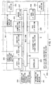
- FIG. 1 shows the construction of an information recording/reproducing apparatus having an authentication function.
- the information recording/reproducing apparatus 1 includes an information recording/reproducing section (physical series block) 200 for reproducing information from an information recording medium (optical disk) 201 or recording information thereon, an authentication functional section 9, a communication functional section 301, a computer connecting interface section 302, a controller 303 for controlling the whole portion of the information recording/reproducing apparatus 1, and a bus line 26 for connecting the above sections.
- an information recording/reproducing section physical series block 200 for reproducing information from an information recording medium (optical disk) 201 or recording information thereon
- an authentication functional section 9 for reproducing information from an information recording medium (optical disk) 201 or recording information thereon
- a communication functional section 301 for reproducing information from an information recording medium (optical disk) 201 or recording information thereon
- a computer connecting interface section 302 for controlling the whole portion of the information recording/reproducing apparatus 1
- a controller 303 for controlling the whole portion of the information recording/reproducing apparatus 1
- a bus line 26 for connecting the above sections.
- the information recording/reproducing apparatus 1 has the communication functional section 301 so as to independently transfer information via a network. Particularly, since it is used as a recording apparatus of a network server, it has various types of communication functions. Generally, it transmits information to clients via a LAN connecting I/F section 304. It is also possible to use a telephone line without using the above network and transmit information to a client or portable terminal which is not directly connected to LAN. When transferring information via the telephone line, it uses NCU sections 305 and 306 for specifying telephone numbers. It transmits information to a client or portable terminal which desires to transmit information by use of an analog signal via a modem I/F section 307.
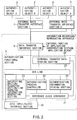
- FIG. 2 shows the relation between the internal construction of the authentication functional section 9 and a peripheral device connected thereto.
- Information reproduced from or recorded on the information recording medium 201 is transferred with respect to the external connection object via a data transfer interface section 8 in the information recording/reproducing apparatus 1.
- an authentication object A:2, authentication object B:3, authentication object C:4, authentication object D:5 are connected as shown in FIG. 2.
- the information recording/reproducing apparatus 1 is connected to a plurality of connection objects as shown in FIG. 2 and the operations described directly below are effected in order to effect the following three operations:
- a previous authentication operation is effected before obfuscated information is transferred with respect to the external connection object.
- the authentication operation is effected by a series of processes as follows.
- the information recording/reproducing apparatus 1 When the connection shown in FIG. 2 is applied to the network system, the information recording/reproducing apparatus 1 is used as a main memory drive of a network server. The information recording/reproducing apparatus 1 independently distributes and collects information according to the distributed processing of the network server.
- the information recording/reproducing apparatus 1 After a client (IP address or telephone number thereof) to or by whom information is distributed or collected and the content of the information to be distributed or collected are informed from the network server, the information recording/reproducing apparatus 1 starts direct communication with the client without using the main CPU of the network server.
- the authentication object A:2, authentication object B:3, authentication object C:4, authentication object D:5 indicate individual client machines (such as PC).
- the data transfer interface section 8 corresponds to a "LAN I/F section", “modem” or “digital communication I/F section such as PHS”
- the external data transfer interface section 1:7 corresponds to a "fire wall”, “router”, “gateway”, or "bridge”.
- the external data transfer interface section 2:6 connected to one client machine corresponds to a "modem", "digital communication I/F section such as PHS” or "LAN I/F section” contained in the client machine.
- the data transfer interface section 8 corresponds to the LAN connection I/F section 304, modem I/F section 307, ISDN I/F section 308 and PHS I/F section 309 in the communication functional section 301 shown in FIG. 1.
- a recording apparatus such as an "HDD”, “CD-ROM”, “MO”, “PD (phase change recording drive)”, DVD-ROM”, “DVD-RAM”, or “semiconductor memory” which is connected via an ATAPI (AT attachment packet interface), SCSI (small computer system interface) or IEEE1394 (serial interface proposed by U.S. Electric and Electronic Engineering Institute) is indicated.
- ATAPI AT attachment packet interface
- SCSI small computer system interface
- IEEE1394 serial interface proposed by U.S. Electric and Electronic Engineering Institute
- the data transfer interface section 8 indicate interface sections such as ATAPI, SCSI, IEEE1394.
- a signal processing section such as an "MPEG encoding/decoding section”, “sound blaster section”, “audio signal compression/expansion section”, “sub-picture run-length board”, or “program execution CPU” is indicated.
- the data transfer interface section 8, external data transfer interface section 7, and external data transfer interface section 6 indicate interface sections such as ATAPI, SCSI, IEEE1394.
- the information recording/reproducing apparatus 1 is constructed by the information recording/reproducing section (physical block) 200 (refer to FIG. 9) which will be described later and which has the data transfer interface section 8, authentication functional section 9 and data input/output interface section 30 shown in FIG. 2, for example.
- the above authentication object has the same construction as that of the authentication functional section 9.
- information of one column of an authentication information recording section 24 as will be described later is stored.
- DVD-video information can be roughly divided into a VGM (video manager) and VTS (video title set).
- the VGM (video manager) includes control information for reproducing a menu or title and the VTS (video title set) is a set of titles having the same construction of various elements constructing video data.
- a set of reproduction video data items in the VTS (video title set) is called a VOBS (video object set).
- the VOBS is a set of VOBs (video objects) having the PS (program stream) structure of MPEG2.
- Each VOB can be divided into cells in the unit of scene according to the purpose of the manufacturer.
- each cell is constructed by a plurality of VOBUs (vide object units).
- FIG. 3 shows the VOBU internal construction recorded on the information recording medium 201. Tracks are continuously formed in a spiral form from the inner periphery towards the outer periphery on the disk-like information recording medium 201 and FIG. 3 shows part of information recorded along the track.
- a pack 10a of FIG. 3 corresponds to a "video pack” in which video information is recorded
- "b pack 10b” corresponds to an "audio pack” in which audio information is recorded.
- audio information is recorded in the form of AC-3 or PCM.
- c pack 10c corresponds to a "sub-picture pack” having information such as a caption or inserted still picture
- "d pack 10d” corresponds to a "navigation pack” for indicating the next access destination.
- the stream formed of a set of packs includes a video data stream, audio data stream, sub-picture data steam, navigation data stream, Dolby/linear audio data stream and the like.
- each authentication object corresponds to one of various types of signal processing boards built in the PC as explained in "[1-5-2] Signal processing section in PC”.
- the authentication object A:2 indicates an MPEG encoder/decoder board
- the authentication object B:3 corresponds to an AC-3 or PCM decoder boarder, sound blaster board or an MPEG audio encoder/decoder board
- the authentication object C:4 corresponds to a sub-picture run-length board or character generator board
- the authentication object D:5 can be made to correspond to the main CPU of PC which is connected via the I/O data line of a main CPU (not shown) and a PCI bus from the SCSI line or the like.
- the main CPU of PC which is the authentication object D:5 receives information of "d pack 10d" which is information of the navigation pack and the main CPU determines the position which is next accessed according to the received information.
- each pack shown in FIG. 3 is divided into a pack header 11 and packet 12 as shown in FIG. 4.
- the pack header 11 includes a 4-byte pack start code, 6-byte system clock reference, 3-byte transfer rate display code and the like.
- the packet 12 is further divided into a packet header 13 and an information content 14 to be transmitted.
- a packet header 13 In the packet header 13, a 3-byte packet start code and a 1-byte stream ID are contained.
- the type (stream) of information to be transferred is described in the stream ID of the packet header 13. More specifically, the content is described as follows:
- the stream ID is the private stream 1 of "10111101”
- a sub-stream ID (1 byte) indicating the type of detail information is recorded in the first position of the "content 14 of transfer information" of FIG. 4. More specifically, the content is as follows.
- the stream ID and sub-stream ID recorded in the packet 12 of FIG. 4 are read out for information reproduced from the information recording medium 201 by use of the authentication functional section 9 of g FIG. 2 and the type of information of each of the packs 10a to 10d is identified.
- the information recording/reproducing apparatus 1 is required to receive images displayed on the CRT of PC according to the distributed processing of PC and, at the same time, receive the software program and audio/video information from a recording device such as an HDD and CD-ROM.
- information recording/reproducing apparatus l when audio information and video information are transferred, it is necessary to provide a good device so as not to interrupt the information in the course of transmission. Therefore, when video information, audio information, software program and text information are simultaneously transferred, it is necessary to finely divide the video information into blocks and intermittently insert other information therebetween. Therefore, in order to cause the information recording/reproducing apparatus l to receive various information items from the exterior and record the received information on the information recording medium 201, information input to the data transfer interface section 8 is divided into blocks having a pack structure or packet structure for each type of information as shown in FIG. 3 and time-divided.
- received information is recorded in a file form on the information recording medium 201.
- An extension is added to each file name and the type of information can be identified by extensions (which can be used instead of the stream ID) such as ".TXT”, “.WAV”, “.BMP”, “.JPEG”, “.MPEG”.
- FIG. 2 The schematic construction of the internal portion of the authentication functional section 9 is shown in FIG. 2.
- the authentication functional section 9 includes a "reference clock generator 21", "authentication process controller 22", “obfuscating section/decoding section/time-changing information generating section 23", “authentication information recording section 24", “external transfer data storing section 25", and a common "bus line 26" for transmitting information between the respective sections.
- the authentication-related processes (five processes) shown as follows are all effected.
- the authenticated information storing section 24 is constructed by a semiconductor memory (for example, EEPROM) and three types of information items necessary for the authentication-related processes are stored therein.
- EEPROM electrically erasable programmable read-only memory
- Transmission/reception of obfuscated information is effected with respect to the authentication objects 2 to 5.
- Obfuscated information used at the time of transmission/reception is stored in the external transfer data storing section 25.
- Information reproduced from the information recording medium 201 and output from the data input/output interface section 30 in the information recording/reproducing apparatus 1 is input to the obfuscating section/decoding section/time-changing information generating section 23 via the bus line 26, obfuscated therein, and then stored in the external transfer data storing section 25 via the bus line 26.
- the data transfer interface section 8 directly reads out data from the external transfer data storing section 25 (at the time of reproduction of data from the information recording medium 201).
- Obfuscated information received from the authentication objects 2 to 5 is also temporarily stored in the external transfer data storing section 25 directly from the data transfer interface section 8.
- obfuscated information is input from the external transfer data storing section 25 to the obfuscating section/decoding section/time-changing information generating section 23 via the bus line 26.
- the obfuscated information is decoded in the obfuscating section/decoding section/time-changing information generating section 23, the information is supplied to the data input/output interface section 30 in the information recording/reproducing section (physical series block) 200 via the bus line 26 (at the time of recording of data on the information recording medium 201).
- the authentication-related process is effected by use of an inherent clock in the authentication functional section 9.
- the inherent clock is created in the reference clock generating section 21.
- the reference clock generated from the reference clock generating section 21 is supplied to the data input/output interface section 30, external transfer data storing section 25 and obfuscating section/decoding section/time-changing information generating section 23.
- Reproduction information subjected to the ECC error correction process is fetched from the information recording/reproducing section 200 which will be described later according to the reference clock by use of the data input/output interface section 30.
- the obfuscating process is effected according to the reference clock by the obfuscating section/decoding section/time-changing information generating section 23 and information obfuscated at a timing defined by the reference clock is stored in the external transfer data storing section 25.
- the timing at which information is processed in the data transfer interface section 8 is different from the timing of the reference clock created in the reference clock generating section 21 and corresponds to the timing of the communication protocol transferred with respect to the external data transfer interface sections 1/2 : 7/6. Further, the data transfer interface section 8 fetches obfuscation information stored in the external transfer data storing section 25 according to the timing of the communication protocol and transmits the information to the exterior.
- the external transfer data storing section 25 acts as a buffer to keep the intermittent data of audio data and the like.
- the transfer rate of information which can be transmitted/received is largely influenced according to the communication state of the communication line between the external data transfer interface sections 1/2 : 7/6 and the data transfer interface section 8.
- the "adaptability at the time of conversion of protocol” and “flexibility for the busy state of the external communication line” can be enhanced by temporarily storing obfuscation information transmitted/received with respect to the exterior into the external transfer data storing section 25 as shown in FIG. 2 and independently generating obfuscation information according to the inherent clock contained therein.
- ATAPI and SCSI are present as a standard interface for the storage device in the computer system such as an HDD, CD-ROM, DVD-ROM, MO, PD, MT.
- Input/output and control of information are effected according to a command determined by ATAPI or SCSI between the storage device and the main CPU of PC.
- Both of the report key command and second key command have the following two features as a common command configuration.
- the report key command is a command used when information is transmitted to the authentication objects 2 to 5 and the operation code is "A4" in the hexadecimal notation.
- the second key command is a command used when information is received from the authentication objects 2 to 5 and the operation code is "A3" in the hexadecimal notation.
- Bus key (which is a common key used for obfuscating and transmitting information)
- the obfuscation technique is an object of the restriction on exports of U.S.A.
- the obfuscation technique with the obfuscation strength of approx. 56 bits can be exported, but it is difficult to export the obfuscation technique with the length more than the above value.
- the upper limit of the obfuscation strength of DES (which is one of the obfuscation systems and uses a symmetric common key) is set to 56 bits in the U.S.A. export restriction for Japan.
- the upper limit of the obfuscation strength of RC4 and RC2 (which is one of the obfuscation systems and uses a symmetric common key) is set to 56 bits (Intra & internet security (Ohm Co. 1996) P.1 : by Takahiro Sugimoto).
- the bus key size is set to 56 bits as a standard.
- the obfuscation key size becomes small, it becomes extremely difficult to acquire the high-level security (prevention of decipher of the obfuscation key by a hacker). It is desirable to set the bus key size to at least 28 bits which is half of 56 bits with the above condition taken into consideration and it is necessary to set the bus key size to at least 14 bits which is 1/4 of 56 bits from the viewpoint of security.
- Obfuscation key 1/2 (key for forming the bus key)
- bus key In order to form the bus key, key information items which are used as a source of formation of the bus key are previously exchanged. Key information transmitted to the authentication objects 2 to 5 is called an "obfuscation key 1" and key information received from the authentication objects 2 to 5 is called an "obfuscation key 2". A bus key is formed by combining the obfuscation keys 1 and 2 according to the same rule in the authentication functional section 9 with the authentication objects 2 to 5.
- the size of the obfuscation key 1/2 is set to 28 bits or more and the size of at least 14 bits is necessary.
- the obfuscation keys 1 and 2 are transmitted or received as they are, they are monitored via the communication line and the obfuscation technique is easily deciphered. In order to prevent this, the obfuscation keys 1 and 2 are obfuscated and then transmitted.
- the obfuscation key for obfuscating the obfuscation key 1/2 is called a challenge key.
- the third party can easily decipher the obfuscation if the third party monitors the whole information in the communication line. Further, in order to enhance the degree of security, a "stream key” and "area key” are used.
- the stream key is an obfuscation key determined for each type of information. For example, if the authentication object A2 is an MPEG encode/decode board and the authentication object B3 is an audio encode/decode board, then a common obfuscation key is previously set for the MPEG encode/decode board corresponding to the video stream.
- the obfuscation key information is known to the authentication object A2 but is not known to the authentication object B3. Therefore, even if information obfuscated by use of the key is monitored by the authentication object B3, the obfuscation cannot be deciphered.
- the stream key is previously stored in the authentication information storing section 24 of FIG. 2.
- the stream key is commonly used by the authentication objects 2 to 5 according to the information contents and information is previously stored as stream key information items 31 to 34 corresponding to information items a to d of FIG. 6A.
- the MPEG encode/decode board is provided not only in the PC (personal computer) directly connected to the information recording/reproducing apparatus 1, but also in the other PC (client) connected via the network. Therefore, there occurs a possibility that information will be monitored by use of the MPEG encode/decode board in the other PC when only the stream key is used. In order to solve this problem, an area key is provided.
- the area key includes specified common keys according to the respective areas shown as follows.
- the area key size and stream key size are half the size of the obfuscation key 1/2.
- a code constructed by connecting the area key and stream key as MSB and LSB is used as an obfuscation key of the challenge key.
- the authentication operation effected with respect to the authentication objects 2 to 5 is effected by exchange of commands (report key command or second key command) on ATAPI or SCSI.
- commands report key command or second key command
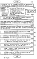
- a portion for transmission by the report key command among the steps in the flowchart of FIG. 5 is indicated by (RK) and a portion for reception by the second key command is indicated by (SK).
- step S101 in which the type of information is determined based on reproduced information from the information recording medium 201, the type of information for each of the packs 10a to 10d is identified based on the stream ID or sub-stream ID recorded in the packet 12 of FIG. 4 as explained in "[2-4] Identification method of information content in DVD-video".
- step S102 of allocating AGID according to the type of information is effected (the detail content thereof is explained in "[7-2] Simultaneous and parallel authentication method").
- a transmission destination area is automatically set (S104) by the authentication process controller 22 according to the scale of the system connected to the information recording/reproducing apparatus 1, corresponding area key information items 35 to 38 are reproduced from the authentication information recording section 24, and the address thereof is informed to the authentication process controller 22. Further, the stream key is read out from the authentication information recording section 24 according to the identified type of information (S105) and the address thereof is informed to the authentication process controller 22.
- the corresponding authentication object A2 independently derives the "stream key” and “area key” from the “stream ID” and “set area information”, combines the two keys to form a combination key and transmits a challenge key (C1) obfuscated by use of the combination key.
- the authentication functional section 9 receives the challenge key (C1) (S107), it comes to know that a candidate of the corresponding authenticated object A2 is present. In parallel with this operation, the authentication functional section 9 independently derives the "stream key” and "area key” to form a combination key and deciphers (decodes) the obfuscated challenge key (C1) by use of the combination key. If the challenge key is precisely deciphered (decoded), it is known that the to-be-transmitted destination is a real authentication object A2.
- a step of transmitting obfuscated information and decoding the same on the reception side is effected for transmission/reception of the "obfuscation key 1" and "obfuscation key 2" as explained in "[5] Obfuscation key".
- the following method is known as a bidirectional subject authentication method and the method is called a "challenge response".
- the "challenge response” is effected.
- the "obfuscation key 1" is formed in the obfuscating section/decoding section/time-changing information generating section 23, obfuscated by use of a challenge key (C1) received from the authentication object A2 and then transmitted to the authentication object A2 (S108).
- a challenge key (C2) is formed by the obfuscating section/decoding section/time-changing information generating section 23, obfuscated by use of a combination key formed by combining the "stream key” and "area key” and then simultaneously transmitted to the authentication objects A2 to D5 (S109). Only the authentication object A2 who is the subject and knows the "steam key” and "area key” can decipher the challenge key (C2).
- the authentication object A2 independently forms the "obfuscation key 2", obfuscates the obfuscation key 2 by use of the received challenge key (C2) and returns the obfuscated key.
- the authentication functional section 9 receives the obfuscated obfuscation key 2 (S110), it decodes the received obfuscation key by use of the challenge key (C2).
- a "bus key” is formed based on the "obfuscation key 1" and “obfuscation key 2" obtained by a series of above steps (S111).
- information to be transferred is obfuscated by use of the bus key and transferred after protocol-converted into a transport stream as described in "[3-7] Conversion of communication protocol and acquirement of timing" (S112).
- information recorded/reproduced on or from the information recording/reproducing medium 201 contains plural types of information items for each pack. Further, as shown in FIG. 2, a plurality of authentication objects 2 to 5 are present. Therefore, it is necessary to simultaneously effect the authentication operations and transfer information with respect to the plurality of authentication objects 2 to 5 in parallel.
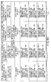
- the history is stored in the authentication information storing section 24 for each authentication step (FIG. 5) effected with respect to the individual authentication objects 2 to 5.
- the history information content stored in the authentication information storing section 24 is shown in FIGS. 6A and 6B.
- the authentication functional section 9 it is possible to simultaneously effect the authentication operation and transfer information with respect to the four authentication objects.
- An ID number (AGID) is allocated for each authentication operation for management.
- the authentication history is recorded in the vertical direction (column direction) for each of the AGID numbers 40 to 43.
- the authentication process controller 22 searches for an available AGID number in the authentication information storing section 24 and stores the authentication history into the column of the available AGID number. When no available AGID number is present, information indicating that the authentication is impossible is informed to the host PC (S103).
- the allocation step of the AGID number corresponds to the step S102 in FIG. 5.
- the authentication histories for the AGID numbers 40 to 43 contain challenge key information items 45 to 48 issued from the other party, challenge key information items 51 to 54 issued from its own side, obfuscation key l information items 55 to 58 issued from its own side, obfuscation key 2 information items 60 to 63 issued from the other side, bus key information items 65 to 68, AGID transmission completion information items 70 to 73, challenge key reception completion information items 75 to 78, obfuscation key 1 transmission completion information items 80 to 83, challenge key transmission completion information items 85 to 88 and obfuscation key 2 reception completion information items 90 to 93.
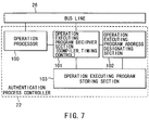
- the authentication process controller 22 can be formed of a CPU and a semiconductor memory (RAM) for storing a program for controlling the CPU. However, in order to more precisely explain the function and flow of signals, function blocks constructing the authentication process controller 22 are shown in FIG. 7 and the authentication process controller includes an operation processor 100, operation executing program decipher section (compiler, timing control) 101, operation executing program address designating section 102, and operation executing program storing section 103.
- operation processor 100 operation executing program decipher section (compiler, timing control) 101
- operation executing program address designating section 102 operation executing program address designating section 102
- operation executing program storing section 103 operation executing program storing section 103.
- An operation execution program for executing the flowchart shown in FIG. 5 is stored in the operation execution program storing section 103.
- the simultaneous and parallel authentication processes can be effected with respect to a plurality of authentication objects 2 to 5 by effecting the following four processes according to the operation execution program.
- a program compile corresponding to the operation executing program stored in the operation executing program storing section 103 is executed in the decipher section 101 and the result thereof is transmitted to the operation processor 100. Further, in the operation executing program decipher section 101, the timing control according to the flowchart shown in FIG. 5 is effected.
- the authentication step shown in FIG. 5 is different for each of the authentication objects 2 to 5.
- the "transmission process (S106) of AGID value allocated to the authentication object A:2" is completed for the authentication object A:2
- the "reception process (S110) of the "obfuscation key 2" obfuscated by use of the challenge key (C2) on its own side” is effected for the authentication object B:3
- the "reception process (S107) of the obfuscated challenge key from the authentication object C:4" is effected for the authentication object C:4.
- the process of the operation processor 100 effected immediately after this includes the following steps (a) to (c).
- the address of the operation execution program storing section 103 in which the program is stored is different for the respective steps (a) to (c).
- the address of the program to be jumped is designated by the operation execution program address designating section 102.
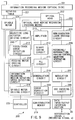
- the obfuscating section/decoding section/time-changing information generating section 23 includes a random signal generator 104, signal synthesizer 105, input/output signal switching controller 106, and shift registers 110a to 110d.
- the "information obfuscating process”, "obfuscated information decoding (obfuscation decipher) process” and "generating process of time-changing information which becomes the base of various obfuscation keys" effected in the obfuscating section/decoding section/time-changing information generating section 23 are processes which are functionally similar to one another. Therefore, the first important feature lies in that one set of the random signal generator 104 and signal synthesizer 105 are commonly used for effecting the three processes. Conventionally, circuits are separately used for effecting the three processes, but in this invention, the circuits are commonly used as shown in FIG. 8, the circuit construction can significantly be simplified and, as a result, the cost can be lowered.
- the random signal generator 104 is simply treated as a series of shift registers 109a to 109d and combined with the signal synthesizer 105 to effect the following two processes.
- the circuit construction can significantly be simplified and, as a result, the cost can be lowered.
- the random signal generator 104 includes shift registers 109a to 109d, operating units 108a, 108b, and selector 107.
- the operating units 108a, 108b are constructed by adders which are exclusive-use OR circuits.
- an output signal i3 of the operating unit 108a is supplied as an input signal i4 of the shift register 109a by the selector 107, the random signal generator 104 is constructed.
- the output signal of the shift register 109a is transmitted to the shift register 109d via the shift registers 109b, 109c.
- An output signal i5 of the shift register 109d is added to an output signal of the shift register 109c in the operating unit 108b, the result of addition is added to an output signal of the shift register 109b in the operating unit 108a, and the result of addition (output signal i3) is input to the shift register 109a again and thus a signal is circulated.
- the output signal i5 of the shift register 109d becomes a random signal.
- the signal synthesizer 105 is constructed by a complicated combination of gates according to the "bus key" forming system or the obfuscating/decoding system.
- the signal synthesizer 105 can attain the function of the obfuscating section/decoding section/time-changing information generating section 23 even if it is constructed only by an adder which is one exclusive-use OR circuit.
- the stream ID and sub-stream ID in the packet 12 shown in FIG. 4 are read from the pack string (FIG. 3) recorded on the information recording medium 201 and a necessary number of AGIDs is checked.
- the "AGID transmission completion information items 70 to 73" in the authentication information storing section 24 are read out and the number of an available AGID (which is not yet used for the authentication process) is searched for.
- the stream key and area key are set according to the procedure explained in "[5-5] Stream key", "[5-6] Area key” and "[6-2] Setting of the authentication object".
- the stream key is selected from the stream key information items 31 to 34 corresponding to the information items a to d in the authentication information recording medium 24 and the area key is selected from the first to fourth area key information items 35 to 38 in the authentication information recording medium 24.
- the "stream ID” and “set area information” are notified together with the set AGID number to the data transfer interface section 8.
- the authentication process controller 22 sets a "1" bit (flag) in a portion of the AGID transmission completion information 70 in the authentication information recording medium 24.
- the notified "AGID number”, "stream ID” and “set area information” are subjected to the format change according to the format of the report key command of ATAPI or SCSI and then transmitted to the authentication object A:2.
- the authentication object A:2 When having received AGID, the authentication object A:2 issues a challenge key, obfuscates the challenge key by use of a combination key formed from the stream key and area key and transmits the same according to the format of Send Key Command of ATAPI or SCSI.
- the obfuscated challenge key formed by the authentication object A:2 is extracted from the format of the Second Key Command of ATAPI or SCSI and stored in the external transfer data storing section 25.
- Information generated from the random signal generator 104 is temporarily saved in the authentication information storing section 24 before decoding (deciphering) the challenge key received from the authentication object A:2. That is, the input/output signal switching controller 106 directly fetches the output signal i5 of the shift register 109d in response to an instruction from the authentication process controller 22 and temporarily holds the same into the "timely time-changing information 39 (FIG. 6A) formed by the random signal generator 104" in the authentication information storing section 24 via the bus line 26.
- the stream key information 32 corresponding to the information b in the authentication information storing section 24 is transmitted to the obfuscating section/decoding section/time-changing information generating section 23 via the bus line 26 according to the program in the operation execution program storing section 103.
- the input/output signal switching controller 106 controls the selector 107 to transmit the stream key information 32 corresponding to the information b to the shift register 109a as it is.
- the first area key information 35 in the authentication information storing section 24 is transmitted to the shift register 109a.
- the information is supplied to the shift register 109a in the same manner as described before.
- the first bit of the stream key information 32 corresponding to the information b reaches the most significant bit position of the shift register 109d and information in the shift registers 109a to 109d is used as the combination key.
- the input/output signal switching controller 106 is operated such that the "obfuscated challenge key" stored in the external transfer data storing section 25 is input as the input signal i2 of the signal synthesizer 105 under the control of the authentication process controller 22.
- a decoded (deciphered) challenge key appears on the output signal i6 of the signal synthesizer 105.
- the decoded (deciphered) challenge key is stored in the address of the "challenge key information 45 issued from the other party" in the authentication information storing section 24 via the shift registers 110a to 110d, input/output signal switching controller 106, and bus line 254.
- the decoding (deciphering) process of the obfuscated challenge key is started immediately after the process of transmission of the first area information 35 to the shift register 109a is completed, but this is not limitative, and it is possible to start the decoding process after the transmission to the shift register 109a was completed and a specified clock has passed.
- the bit (flag) of the challenge key reception completion information 75 is set to "1".
- the obfuscating section/decoding section/time-changing information generating section 23 re-starts generation of time-changing information. That is, timely time-changing information 39 (FIG. 6A) formed by the random signal generator 104 and temporarily stored in the authentication information storing section 24 is input to the shift register 109a as an input signal i4 via the bus line 26, input/output signal switching controller 106 and selector 107 according to the control of the authentication process controller 22.
- the selector 107 is closed, the output signal i3 of the operating unit 108a is returned to the input signal i4 of the shift register 109a and a random signal which is time-changing information is successively generated again.
- time-changing information is normally generated in the random signal generator 104
- various types of obfuscation keys can be formed by extracting the time-changing information at a specified timing.
- the output signal i5 of the random signal generator 104 is input to the input/output signal switching controller 106 as an "obfuscation key 1" in response to an instruction from the operation processor 100 according to the program of the operation execution program storing section 103 and stored in the "obfuscation key 1 information 55 issued from its own side" (FIG. 6A) in the authentication information storing section 24 via the bus line 26.
- "6 Temporary saving process of time-changing information
- the challenge key from the address of the "challenge key information 45 issued from the other party" in the authentication information storing section 24 is input to the shift registers 109a to 109d as an input signal i4 via the bus line 26, input/output signal switching controller 106 and selector 107 according to the control of the authentication process controller 22.
- the output signal i5 of the challenge key is input to the signal synthesizer 105.
- the selector 107 is closed, the output signal of the operating unit 108a is output to the shift register 109a and circulated in the random signal generator 104 by a specified clock, and then the obfuscation key 1 from the address of the "obfuscation key 1 information 55 issued from its own side" in the authentication information storing section 24 is input to the signal synthesizer 105 as an input signal i2 via the bus line 26 and input/output signal switching controller 106.
- the output signal i6 of the signal synthesizer 105 is used as the obfuscated obfuscation key 1 and stored into the external transfer data storing section 25 via the input/output signal switching controller 106 and bus line 26.
- the bit (flag) of the address of the "obfuscation key 1 transmission completion information 80" in the authentication information storing section 24 is set to "1" and then "8) Re-start process of generation of time-changing information" is effected.
- the data transfer interface section 8 reads out the obfuscated obfuscation key 1 from the external transfer data storing section 25, converts the format thereof according to the format of the report key command of ATAPI or SCSI, and transmits the same to the authentication object A:2.
- the challenge key is formed in the same manner as that in "9) Formation of the challenge key 1" and stored in the address of the "challenge key information 51 issued from its own side".
- the combination key is loaded into the shift registers 109a to 109d in the same manner as that in "7) Formation of the combination key and decoding process of the challenge key” and the challenge key is obfuscated.
- an obfuscated signal can be obtained as the output signal i6 when an original signal is input as the input signal i2 to the signal synthesizer 105 and a decoded (deciphered) signal can be obtained as the output signal i6 when an obfuscated signal is input as the input signal i2 to the signal synthesizer 105. This is because the result returns to the original signal when the signal of "0" or "1" is added twice as the obfuscation key signal.
- the obfuscated challenge key is stored in the external transfer data storing section 25 and the bit (flag) of the address of the "challenge key transmission completion information 85" is set to "1". Further, the process is returned to "8) Re-start process of generation of time-changing information".
- the obfuscation key 1 is transmitted to the authentication object A:2 by use of the report key command.
- the "obfuscation key 1 information issued from its own side" is input as the input signal i4 from the authentication information storing section 24 to the shift registers 109a to 109d via the bus line 26, input/output signal switching controller 106 and selector 107.
- the shift registers 109a to 109d are used as a temporary storing location of the "obfuscation key 1 information issued from its own side".
- the "obfuscation key 1 information issued from its own side” is filled up to the shift register 109d
- the "obfuscation key 2 information issued from the other party” is input as the input signal i2 to the signal synthesizer 105 via the bus line 26 and input/output signal switching controller 106, and the obfuscation key 1 and obfuscation key 2 are combined in the signal synthesizer 105.
- the output signal i6 of the signal synthesizer 105 is used as the bus key and stored in the address of the "bus key information 65" of the authentication information storing section 24.
- the "bus key information 65" is input as the input signal i4 from the authentication information storing section 24 to the shift registers 109 via the bus line 26, input/output signal switching controller 106 and selector 107 according to the control of the authentication process controller 22.
- the selector 107 is closed and a signal is circulated in the random signal generator 104 with the bus key used as the starting point. The circulation of the signal is continued if obfuscation of the reproduced signal is continued.
- Information reproduced from the information storing medium 201 is input as the input signal i2 from the data input/output interface section 30 to the signal synthesizer 105 via the bus line 26 and input/output signal switching controller 106 and obfuscated information which is the output signal i6 of the signal synthesizer 105 is stored into the external transfer data storing section 25 via the shift registers 110d to 110a, input/output signal switching controller 106 and bus line 26.
- the authentication procedure with respect to one authentication object A:2 has been explained. As is clearly understood from the above explanation, since the authentication history is stored in the authentication information storing section 25 for each step, the authentication procedure can be interrupted on the way and the authentication procedure with respect to another authentication object B:3 can be effected.
- the authentication method on the network system is explained in "[1-4] Concrete example of information transfer in the network system".
- the relation between the steps of the authentication procedure flowchart shown in FIG. 5 and the communication content on the network is explained by using TCP/IP as an example of the communication protocol.
- the authentication process is started from reproduced information of the information recording medium 201 in "[8] Flow of signals at the time of authentication operation", but in the authentication process on the network system, the authentication process is not started until the client (IP address and telephone number thereof) to or by whom information is distributed or collected and the content of information to be distributed and collected are informed from the network server as explained in "[1-4] Concrete example of information transfer in the network system".
- the authentication object A:2 since a special IP address or telephone number to be connected is specified by the client, the authentication object A:2 is previously fixed. Therefore, the "step (S106) of transmitting the value of AGID, area information and stream ID information allocated to the authentication object" of FIG. 5 is effected with respect to the previously fixed authentication object. In this case, the steps effected after this are the process for sharing the obfuscation key for acquirement of high-level security and prevention of leakage at the time of information transfer.
- the concrete content of the process is the same as that in "[8-3] Flow of concrete signals at the time of authentication operation".
- a plurality of clients may simultaneously be specified by the server in some cases. If information to be transmitted is highly secret information, individual clients are considered as different authentication objects A:2 to D:5 and the authentication operation is effected by separately effecting the communications. In other cases, the same operation as that in "[9-2] A case wherein a special client is specified by the server" is effected.
- the server stores a list of client machine names and IP addresses of clients to be communicated with the server himself in a file of "hosts". Further, the server holds a network domain which the server manages and manages the client machines contained in the network domain by use of IP addresses or the like. It is required in some cases that the range of clients to or by which information is transmitted or received is specified instead of specifying the client of information transferring destination by the server with respect to the information recording/reproducing apparatus 1, searches for a corresponding client from the range of clients and transmits or receives information with respect to the corresponding client. At this time, as the range of clients specified by the server with respect to the information recording/reproducing apparatus 1, the "hosts" itself or an IP address list of the client machines contained in the specified domain is given.
- step (S104) of setting an area key corresponding to an area in which the authentication object belongs corresponds to recognition of the network domain notified by the server and extraction of an area key which is an obfuscation key previously set for each network domain.
- Information of the area key corresponding to the network domain is previously stored in the authentication information storing section 24 of FIG. 2.
- the data transfer interface section 8 having the communication function is controlled to simultaneously effect the "step (S106) of transmitting the value of AGID, area information and stream ID information allocated to the authentication object" of FIG. 5 with respect to all of the clients contained in the IP address list. Some information items relating to the content of information to be transmitted based on a different format may be transmitted to the client instead of stream ID information. If the step is effected, an answer is returned in the form of "self-request" from the client who wants to receive information in the network or the client who requires information transmission. That is, an answer comes back in the form of the "step (S107) of receiving the challenge key obfuscated from the authentication object" who is the client.
- the authentication process controller 22 extracts the IP address of the authentication object A:2 from the received communication packet and stores the same into the authentication information storing section 24 of FIG. 2. After this, the IP address thus stored is used to effect the authentication operation with respect to the authentication object A:2. That is, all the steps effected after the "step (S108) of transmitting the "obfuscation key 1" obfuscated by use of the challenge key of the authentication object" are effected to communicate with only the client having the extracted IP address.
- step (S106) of transmitting the value of AGID, area information and stream ID information allocated to the authentication object" and answers are sent from the plurality of clients, the clients are divided into different authentication objects B:3,, C:4, D:5 and the individual authentication operations are effected.
- the clients In order to prevent illegal coping of information and leakage of information on the way of the network, it is preferable to regard the clients as different authentication objects and separately effect the authentication operations.
- the following operations are effected in the information recording/reproducing section 200.
- the optical head 202 is basically constructed by a semiconductor laser which is a light source, photodetector and an objective lens although they are not shown in the drawing.
- Laser light emitted from the semiconductor laser is converged on the information recording medium (optical disk) 201 by the objective lens.
- the laser light reflected from the light reflection film or light reflective recording film of the information recording medium (optical disk) 201 is photoelectrically converted by the photodetector.
- a detection current obtained in the photodetector is subjected to current-voltage conversion and converted to a detection signal in an amplifier 213.
- the detection signal is processed by a focus/track error detection circuit 217 or binary coding circuit 212.
- the photodetector is divided into a plurality of light detection areas to individually detect a variation in the amount of light applied to each light detection area.
- a signal on the information recording medium (optical disk) 201 is reproduced by detecting a variation in the amount of reflected light from the light reflective recording film or light reflection film of the information recording medium 201.
- the information recording medium (optical disk) 201 has a spiral track or concentric tracks and information is recorded on the track.
- a converged light spot is traced along the track to reproduce or record/erase information.
- the track deviation detecting method the following methods are provided.
- An objective lens (not shown) for converging the laser light emitted from the semiconductor laser element on the information recording medium 201 has such a structure as to be moved in two axial directions according to an output current of the objective lens actuator driving circuit 218.
- the directions of movement of the objective lens are as follows:
- the moving mechanism of the objective lens is called an objective lens actuator, although not shown in the drawing.
- the objective lens actuator structure As the objective lens actuator structure, the following structures are provided.
- a permanent magnet and a coil are provided and the blade is moved by causing a current to flow into the coil connected to the blade.
- the information recording medium (optical disk) 201 is mounted on a rotating table 221 rotated by a driving force of a spindle motor 204.
- the rotation speed of the information recording medium 201 is detected based on the reproduction signal obtained from the information recording medium 201. That is, a detection signal (analog signal) output from the amplifier 213 is converted into a digital signal by the binary coding circuit 212 and a signal of constant frequency (reference clock signal) is generated based on the above signal by a PLL circuit 211.
- An information recording medium rotation speed detection circuit 214 uses the signal to detect the rotation speed of the information recording medium 201 and outputs the value thereof.
- a correspondence table indicating information recording medium rotation speeds corresponding to radial positions for reproduction or recording/erasing on the information recording medium 201 is previously recorded on a semiconductor memory 219. If a reproduction position or recording/erasing position is determined, a control section 220 refers to information of the semiconductor memory 219, sets the target rotation speed of the information recording medium 201 and notifies the value to the spindle motor driving circuit 215.
- the spindle motor driving circuit 215 a difference between the target rotation speed and the output signal (current rotation speed) of the information recording medium rotation speed detection circuit 214 is derived and the driving current corresponding to the result is supplied to the spindle motor 204 so as to control the rotation speed of the spindle motor 204 to be set at a constant value.
- the output signal of the information recording medium rotation speed detection circuit 214 is a pulse signal having a frequency corresponding to the rotation speed of the information recording medium 201.
- the spindle motor driving circuit 215 controls both of the frequency and pulse phase of the pulse signal.
- An optical head moving mechanism (feeding motor) 203 for moving the optical head 202 in the radial direction of the information recording medium 201 is provided.
- a rod-like guide shaft is used as a guide mechanism for moving the optical head 202 in many cases, and the optical head 202 is moved by use of friction between a bush mounted on part of the optical head 202 and the guide shaft. Further, a method using a bearing for alleviating the friction force using the rotation movement is provided.
- the driving force transmission method for moving the optical head 202 can be attained by disposing a rotating motor with a pinion (rotating gear) on the fixed system and a rack which is a linear gear engaged with the pinion on the side surface of the optical head 202 although they are not shown in the drawing so as to convert the rotation movement of the rotating motor into a linear movement of the optical head 202.
- a linear motor system for disposing a permanent magnet on the fixed system and supplying a current to a coil arranged on the optical head 202 to linearly move the optical head may be used as the other driving force transmission method.
- a current is basically supplied to the feeding motor to generate a driving force for moving the optical head 202.
- the driving current is supplied from the feeding motor driving circuit 216.
- the objective lens actuator driving circuit 218 is used as a circuit for supplying the driving current to an objective lens actuator (not shown) in the optical head 202 according to an output signal (detection signal) of the focus/track error detection circuit 217.
- a phase compensation circuit for improving the characteristic according to the frequency characteristic of the objective lens actuator is contained therein.
- the following processes are effected in response to an instruction of the controller 220.
- the switching process for reproducing and recording/erasing is effected by changing the light amount of the converged light spot applied to the information recording medium 201.
- the recording and erasing operations are controlled by changing the polarity of an external magnetic field (not shown) applied to the information recording medium 201 at the time of recording/erasing.
- the semiconductor laser element When new information is recorded, an intermittent light amount in a pulse form is superimposed on the light amount at the time of reproduction.
- the semiconductor laser element emits pulse-like light with a large light amount, the light reflective recording film of the information recording medium 201 is partially optically changed or deformed to form a recording mark.
- the semiconductor laser element When information is written on the already recorded area, the semiconductor laser element is also driven to emit pulse-like light.
- a photodetector for detecting the emitted light amount of the semiconductor laser element is contained in the optical head 202 although not shown in the drawing.
- a semiconductor laser driving circuit 205 a difference between the output (detection signal of the emitted light amount of the semiconductor laser element) of the photodetector thereof and a light emission reference signal generated from a recording/reproduction/erasing control waveform generating circuit 206 is derived and a driving current is fed back to the semiconductor laser based on the result.
- Information indicating the content and location of information recorded on the information recording medium 201 is different depending on the type of the information recording medium 201 and the information is generally stored in the following location in the information recording medium 201:
- the radial position of the access destination is derived by calculation in the optical head 220 and a distance with respect to the present position of the optical head 202 is derived.
- Speed curve information indicating the shortest time for the traveling distance of the optical head 202 is previously recorded in the semiconductor memory 219.
- the controller 220 reads out the information and controls the movement of the optical head 202 according to the speed curve by the following method.
- a command is issued from the controller 220 to the objective lens actuator driving circuit 218 to set the track loop into the OFF state and then the feeding motor driving circuit 216 is controlled to start to move the optical head 202.
- a track error detection signal is generated in the focus/track error detection circuit 217.
- the relative speed of the converged light spot with respect to the information recording medium 201 can be detected by use of the track error detection signal.
- the feeding motor driving circuit 216 a difference between the relative speed of the converged light spot obtained from the focus/track error detection circuit 217 and the target speed information sequentially supplied from the controller 220 is derived and the result thereof is fed back to the driving current to the optical head driving mechanism (feeding motor) 203 to move the optical head 202.
- Friction force is always applied between the guide shaft and the bush or bearing as described in "[11-3] Optical head moving mechanism".
- the friction force acts, but at the starting time of movement and immediately before stop, the optical head 202 moves at slow speed and the static friction occurs.
- the current amplification factor (gain) of the current supplied to the optical head driving mechanism (feeding motor) 203 is increased according to the command from the controller 220.
- the converged light spot is traced along the track on the information recording medium 201 to reproduce the address or track number of a traced portion.
- the present converged light spot position is derived based on the address or track number of the traced portion and a difference in the track number from the target position is calculated in the controller 220 and the number of tracks necessary for the movement of the converged light spot is notified to the objective lens actuator driving circuit 218.
- the objective lens actuator driving circuit 2118 When one set of kick pulses are generated in the objective lens actuator driving circuit 218, the objective lens is slightly moved in the radial direction of the information recording medium 201 to move the converged light spot to the adjacent track.
- the track loop is temporarily set into the OFF state in the objective lens actuator driving circuit 218, and after kick pulses are generated by a number of times corresponding to information from the controller 220, the track loop is set into the ON state again.
- the controller 220 After completion of the dense access, the controller 220 reproduces information (address or track number) in the position traced by the converged light spot and confirms that the target track is accessed.
- a track error detection signal output from the focus/track error detection circuit 217 is input to the feeding motor driving circuit 216.
- the controller 220 effects the control operation so that the track error detection signal will not be used in the feeding motor driving circuit 216 at the time of "start control” and "access control” as described before.
- part of the track error detection signal is supplied as a driving current to the optical head driving mechanism (feeding motor) 203 via the motor driving circuit 216 in response to a command from the controller 220.
- the control operation is continuously effected while the continuous reproduction or recording/erasing process is being effected.
- the information recording medium 201 is mounted with its central position slightly eccentrically set from the central position of the rotating table 221.
- the whole portion of the optical head 202 slightly vibrates due to the eccentricity.
- the converged light spot position is gradually moved outwardly or inwardly.
- the optical head driving mechanism (feeding motor) 203 When part of the track error detection signal is supplied as the driving current to the optical head driving mechanism (feeding motor) 203, the optical head 203 is gradually moved outwardly or inwardly accordingly.
- the load of the objective lens actuator for correction of the track deviation can be alleviated and the track loop can be stabilized.
- Information which is desired to be recorded on the information recording medium 201 is input to the data input/output interface section 30 as a recording signal d in the form of live signal.
- the recording signal d is recorded in the semiconductor memory 219 as it is and then the ECC adding process is effected in an ECC encoding circuit 208 as follows.
- the recording signal d is sequentially arranged for every 172 bytes on each row in the semiconductor memory 219 and one set of ECC block is constructed by 192 rows.
- An inside code PI of 10 bytes is calculated for each row of 172 bytes for the live signal (recording signal d) in one set of ECC block constructed by "rows: 172 ⁇ columns: 192 bytes" and additionally recorded in the semiconductor memory 219.
- an outside code PO of 16 bytes is calculated for each column in the unit of bytes and additionally recorded in the semiconductor memory 219.
- information is recorded on the information recording medium 201
- ECC encoding circuit 208 when addition of the inside code PI and outside code PO is completed, a signal is read out from the semiconductor memory 219 for every 2366 bytes of one sector and transferred to a modulation circuit 207.
- a conversion table indicating the relation between the original signals and signals after modulation is stored in the modulation circuit 207 and demodulation circuit 210.
- a signal transferred from the ECC encoding circuit 208 is divided into a plurality of bits according to the modulation system and converted into another signal (code) while referring to the conversion table.
- the following two types of recording systems are generally provided.
- the recording waveform as described above is formed according to the recording signal supplied from the modulation circuit 207 and is transmitted to the semiconductor laser driving circuit 205.
- a signal on the information recording medium 201 is reproduced by detecting a variation in the light amount reflected from the light reflective recording film or light reflection film of the information recording medium (optical disk) 201 as described in "[11-1-1] Signal detection by the optical head 202".
- a signal obtained from the amplifier 213 takes an analog form. The signal is converted into a binary digital signal constructed by "1” and "0” by use of a comparator in the binary coding circuit 212.
- the PLL circuit 211 contains a variable frequency oscillator. The frequencies and phases of a pulse signal (reference clock) output from the oscillator and an output signal of the binary coding circuit 212 are compared and the results of comparison are fed back to the oscillator output.
- a conversion table indicating the relation between the modulated signals and the signals after demodulation is stored in the demodulation circuit 210.
- the signal is restored to an original signal while referring to the conversion table according to the reference clock obtained in the PLL circuit 211.
- the restored (demodulated) signal is recorded in the semiconductor memory 219.
- An erroneous portion is detected for the signal recorded in the semiconductor memory 219 by use of the inside code PI and outside code PO and a pointer flag of the erroneous portion is set.
- a signal in the erroneous portion is corrected according to the error pointer flag while reading out the signal from the semiconductor memory 219, the inside code PI and outside code PO are removed from the signal and then the signal is transferred to the data input/output interface section 30.
- a signal supplied from the ECC encoding circuit 208 is output from the data input/output interface section as a reproduction signal c.
- FIG. 10 The construction of a personal computer system using the information recording/reproducing apparatus 1 is shown in FIG. 10.
- the data transfer interface section 8 corresponds to the interface circuit for SCSI or ATAPI provided in the information recording/reproducing apparatus 1, information reproducing apparatus 122 or the like and the external data transfer interface section 7 corresponds to a SCSI board 138, IDE controller 120, or IEEE1394 I/F board 132.
- the main CPU 111 in the personal computer 150 includes a memory data line 114 for directly input or output information with respect to a main memory 112, and a memory address line 113 for designating the address of information recorded in the main memory 112.
- the execution process of the main CPU 111 proceeds according to the program loaded in the main memory 112. Further, the main CPU 111 transfers information with respect to various controllers via an I/O data line 146 and specifies a controller of the information transferring destination and the content of information to be transferred by address designation of an I/O address line 145.
- An LCD controller 115 for controlling the display content of a CRT display 116 exchanges information with respect to the main CPU 111 via the memory data line 114. Further, in order to realize the high resolution and abundant display colors, a video RAM 117 is provided as a memory exclusively used for the CRT display 116. The LCD controller 115 can directly receive information from the main memory 112 via the memory data line 114 to display an image on the CRT display 116.
- Ten key information input via a keyboard 119 is converted by a keyboard controller 118 and input to the main CPU 111 via the I/O data line 146.
- an IDE interface is used in many cases. Reproduction information from the HDD 121 or information reproducing apparatus 122 or recording information into the HDD 121 is transferred to the I/O data line 146 via the IDE controller 120.
- the main CPU 111 accesses the HDD 121 at the starting time of the personal computer system 150 and necessary information is transferred to the main memory 112.
- a serial line and parallel line are prepared for information transfer with respect to the external device of the personal computer system 150.
- a parallel I/F controller 123 for controlling the parallel line as is represented by "centro" is used to directly drive a printer 124 or scanner 125 without using a network, for example.
- Information transferred from the scanner 125 is transferred to the I/O data line 146 via the parallel I/F controller 123. Further, information transferred on the I/O data line 146 is transferred to the printer 124 via the parallel I/F controller 123.
- the information is first transferred to the I/O data line 146 via the main CPU 111, protocol-converted in the parallel I/F controller 123 and then output to the printer 124.
- the information transferred by the I/O data line 146 is protocol-converted by the serial I/F controller 130 and output as an RS-232C signal e, for example.
- the personal computer system 150 has various bus lines for function extension.
- a desktop personal computer has a PCI bus 133 and EISA bus 126 as bus lines in most cases. Each bus line is connected to the I/O data line 146 and I/O address line 145 via a PCI bus controller 143 or EISA bus controller 144.
- Various boards connected to the bus lines are divided into boards exclusively used for the EISA bus 126 and boards exclusively used for the PCI bus 133. Since the PCI bus 133 is relatively suitable for high-speed transfer, the number of boards connected to the PCI bus 133 is larger in FIG. 9. However, this is not limitative, and if the boards exclusively used for the EISA bus 126 are used, for example, a LAN board 139 or SCSI board 138 can be connected to the EISA bus 126.
- a speech signal input via a microphone 128 is converted into digital information by the sound blaster board 127and input to the main memory 112, HDD 121 or information recording/reproducing apparatus 1 via the EISA bus 126, I/O data line 146 and processed therein.
- a digital sound source signal is transferred to the sound blaster board 127 via the I/O data line 146, EISA bus 126, converted into an analog signal and output from a speaker 129.
- the DSP 137 board exclusively used for the process can be connected to the bus line.
- the SCSI interface is often used for input/output of information with respect to the external memory device.
- the protocol conversion or transfer information format conversion for transferring SCSI format information input or output with respect to the external memory device such as an information backup MT (magnetic tape) 142, external stationary HDD 141, information recording/reproducing apparatus 1 to the PCI bus 133 or EISA bus 126 is effected in the SCSI board 138.
- Multimedia information such as speech, still picture or moving picture is compressed and recorded on the HDD 121, 141, or information recording/reproducing apparatus 1 (information reproducing apparatus 122).
- Information recorded on the HDD 121, 141, information recording/reproducing apparatus 1, or information reproducing apparatus 122 is expanded and displayed on the CRT display 116 or activates the speaker 129. Further, a speech signal input via the microphone 128 is compressed and recorded on the HDD 121, 141, or information recording/reproducing apparatus 1.
- Various exclusive-use boards have the information compression/expansion function.
- the operation of compressing/expanding music or speech signal is effected by a speech coding/decoding board 136
- the operation of compressing/expanding a moving picture (video image) is effected by an MPEG board 134
- the compressing/expanding operation of sub-picture is effected by a sub-picture run-length board 135.
- a modem 131 When it is desired to transfer information to the exterior via the telephone line f, a modem 131 is used. That is, in order to connect the telephone line to a desired destination, an NCU (Network Control Unit) transmits a telephone number of the destination to the telephone exchange via the telephone line f although not shown in the drawing.
- the serial I/F controller 130 effects the transfer information format conversion and protocol conversion for information on the I/O data line 146.
- An RSC-232C signal of digital signal obtained as the result of conversion is converted into an analog signal by the modem 131 and then transferred to the telephone line f.
- IEEE1394 uses an isochronous transfer system in which data transfer is completed for every 125 ⁇ s.
- IEEE1394 the isochronous transfer and normal asynchronous transfer are mixedly used, but the upper limit of the asynchronous transfer time of one cycle is set to 63.5 ⁇ s at maximum. If the asynchronous transfer time is excessively long, the isochronous transfer cannot be ensured.
- a SCSI command instruction set
- the process of automatically setting of topology such as node setting, information format conversion and protocol conversion for isochronous transfer is effected for information transferred via the PCI bus 133 by an IEEE1394 I/F board 132.
- the IEEE1394 I/F board 132 has not only a function of transferring information held in the personal computer system 150 to the exterior as an IEEE1394 signal g, but also a function of converting the IEEE1394 signal g transferred from the exterior and then transferring the converted signal to the PCI bus 133.
- a LAN signal h is input or output with the LAN cable used as a medium although not shown in the drawing.
- TCP/IP, NetBEUI are present as the communication protocol using LAN and have inherent data packet structures (information format structures) corresponding to the protocols.
- the LAN board 139 effects the communication procedure with the exterior corresponding to various protocols and information format conversion with respect to information transferred on the PCI bus 133.
- the procedure and information transfer path in a case wherein specified file information recorded in the HDD 121 is converted into a LAN signal h and transferred to an external personal computer, EWS or network server (not shown) are explained.
- a file directory recorded in the HDD 121 is output, and the main CPU 111 records the file list of the result in the main memory 112 and displays the same on the CRT display 116.
- the main CPU 111 When the user inputs a file name which he wants to transfer by use of the keyboard 119, the content thereof is recognized by the main CPU 111 via the keyboard controller 118.
- the HDD 121 determines and accesses the internal information recording location and reproduced information is transferred to the I/O data line 146 via the IDE controller 120.
- the information is transferred to the LAN board 139 via the PCI bus 133.
- the LAN board 139 establishes a session with the transfer destination by a series of communication processes, then receives file information from the PCI bus 133, converts the information into a data packet structure according to the protocol to be transferred, and transfers the converted information as a LAN signal h to thee exterior.
- the information reproducing apparatus 122 which is an optical disk device exclusively used for reproduction such as a CD-ROM, DVD-ROM and the information recording/reproducing apparatus 1 which is a recordable and reproducible optical disk device such as a DVD-RAM, PD, MO are contained in the personal computer system 150, "IDE”, “SCSI”, and "IEEE1394" are present as a standard interface.
- the PCI bus controller 143 and EISA bus controller 144 have a DMA therein. It is possible to transfer information between the blocks without using the main CPU 111 by the control of the DMA.
- the process of the main CPU 111 is only to issue a transfer instruction to the PCI bus controller 143 and the information transfer management is left to the DMA of the PCI bus controller.
- the main CPU 111 can execute another process in parallel without being obstructed by the information transfer process.
- the main CPU 111 when information recorded in the information reproducing apparatus 122 is transferred to the HDD 141, the main CPU 111 only issues a transfer instruction to the PCI bus controller 143 or IDE controller 120 and the information transfer management is left to the DMA of the PCI bus controller 143 or DMA of the IDE controller 120.
- the information transfer management is effected by the DMA of the PCI bus controller 143, EISA bus controller 144 or IDE controller 120.
- the actual transfer process is effected by the authentication functional section of the information recording/reproducing apparatus 1 or information reproducing apparatus 122.
- a bit stream of video, audio is recorded in the MPEG2 Program stream format and an audio stream, video stream, sub-picture stream, private stream and the like are mixedly recorded.
- the information recording/reproducing apparatus 1 separately extracts the audio stream, video stream, sub-picture stream, private stream and the like from the program stream at the time of information reproduction and selectively transfers them to the speech coding/decoding board 136, MPEG board 134 or sub-picture run-length board 135 via the PCI bus 133 without using the main CPU 111.
- the information reproducing apparatus 122 separately extracts various stream information items from the program stream reproduced therefrom and selectively transfers the individual stream information items to the speech coding/decoding board 136, MPEG board 134 or sub-picture run-length board 135 via the I/O data line 146, PCI bus 133 without using the main CPU 111.
- the speech coding/decoding board 136, MPEG board 134 or sub-picture run-length board 135 itself has authentication function therein.
- the information recording/reproducing apparatus 1, information reproducing apparatus 122 and the speech coding/decoding board 136, MPEG board 134, sub-picture run-length board 135 authenticate each other via the PCI bus 133 (and I/O data line 146).
- video stream information reproduced in the information recording/reproducing apparatus 1 and information reproducing apparatus 122 is transferred only to the MPEG board 134.
- audio stream information is transferred only to the speech coding/decoding board 136.
- a still picture stream is transferred to the sub-picture run-length board 135 and the private stream or text information is transferred to the main CPU 111.
- a report key command including AGID, set area information, and steam ID from the information recording/reproducing apparatus 1 is output to the MPEG board 134 (1).
- the MPEG board 134 reads out a previously stored stream key and area key according to the AGID, set area information and stream ID (sub-stream ID) received, forms a challenge key A obfuscated by a combination key constructed by the readout stream key and area key, and outputs a second key command including the obfuscated challenge key A to the information recording/reproducing apparatus 1 (2).
- the information recording/reproducing apparatus 1 forms a obfuscation key 1 obfuscated by use of the received challenge key A and outputs a report key command constructed by the obfuscated obfuscation key 1 to the MPEG board 134 (3).
- the information recording/reproducing apparatus 1 reads out the previously stored stream key and area key, forms a challenge key B obfuscated by use of a combination key constructed by the readout stream key and area key, and outputs a report key command including the challenge key B to the MPEG board 134 (4).
- the MPEG board 134 outputs a second key command containing an obfuscation key 2 obfuscated by use of the received challenge key B to the information recording/reproducing apparatus 1 (5).
- the information recording/reproducing apparatus 1 forms a bus key based on an obfuscation key 2 deciphered from the obfuscated obfuscation key 2 received and the above formed obfuscation key 1 (6).
- the MPEG board 134 forms a bus key based on an obfuscation key 1 deciphered from the obfuscated obfuscation key 1 received and the above formed obfuscation key 2 (6).
- an obfuscated challenge key is transmitted from the other party, that is, when a challenge key is supplied from the MPEG board 134 via the external data transfer interface section 7 and data transfer interface section 8, the challenge key is stored into the external transfer data recording section 25.
- an output signal of the random signal generator 104 in the obfuscating section/decoding section/time-changing information generating section 23 is used as the obfuscation key 1 and the output signal i5 from the shift registers 109a to 109d is stored into the obfuscation key 1 information 55 issued from its own side in the authentication information storing section 24 via the input/output signal switching controller 106 and bus line 26.
- the following numeral of one unit from the random signal generator 104 is treated as time-changing information, that is, the output signal i5 of the shift registers 109a to 109d is registered into the timely time-changing information 39 formed by the random signal generator 104 of the authentication information storing section 24 via the input/output signal switching controller 106 and bus line 26.
- stream information 31 corresponding to information a of the authentication information storing section 24 is read out and output to the selector 107 via the bus line 26 and input/output signal switching controller 106 and supplied to the shift register 109a.
- first area key information 35 is read out and output to the selector 107 via the bus line 26 and input/output signal switching controller 106 and supplied to the shift register 109a.
- the stream key is input to the shift registers 109a, 109b and the first area key is input to the shift registers 109c, 109d.
- the obfuscated challenge key stored in the external transfer data storing section 25 is output as the input signal i2 to the signal synthesizer 105 via the bus line 26 and input/output signal switching controller 106.
- the signal synthesizer 105 decodes the challenge key obfuscated by the combination key supplied and outputs the result of decoding to the shift registers 110d to 110a.
- the entire portion of the decoded challenge key is input to the shift registers 110d to 110a.
- the challenge key output from the shift registers 110d to 110a is stored into the challenge key information 45 issued from the other party in the authentication information storing section 24 via the input/output signal switching controller 106 and bus line 26.
- the obfuscation key 1 information 55 issued from its own side is obfuscated by use of the challenge key information 45 issued from the other party.
- the challenge key information 51 issued from its own side is read out from the authentication information storing section 24, output to the selector 107 via the bus line 26 and input/output signal switching controller 106 and supplied to the shift register 109a.
- the challenge key information 51 issued from its own side is input to the shift registers 109a to 109d.
- the challenge key information 51 is output to the signal synthesizer 105 as the output signal i5 of the shift registers 109a to 109d.
- the obfuscation key 1 information 55 issued from its own side is read out from the authentication information storing section 24 and output to the signal synthesizer 105 via the bus line 26 and input/output signal switching controller 106 as the input signal i2.
- the signal synthesizer 105 obfuscates the obfuscation key 1 information 55 received by use of the challenge key information 51 and outputs the obfuscated obfuscation key 1 to the shift registers 110d to 110a.
- the obfuscated obfuscation key 1 output from the shift registers 110d to 110a is stored into the external transfer data storing section 25 via the input/output signal switching controller 106 and bus line 26.
- a report command or the like is added to the obfuscated obfuscation key 1 stored in the external transfer data storing section 25 and then supplied to the MPEG board 134 via the data transfer interface section 8 and external data transfer interface section 7.
- the timely time-changing information 39 formed in the random signal generator 104 of the authentication information storing section 24 is read out, output to the selector 107 via the bus line 26 and input/output signal switching controller 106 and supplied to the shift registers 109a to 109d.
- the bus key is formed by use of the obfuscation key 1 and obfuscation key 2.
- the obfuscation key 1 information 55 issued from its own side is read out from the authentication information storing section 24, output to the selector 107 via the bus line 26 and input/output signal switching controller 106 and then supplied to the shift register 109a.
- the obfuscation key 1 information 55 issued from its own side is input to the shift registers 109a to 109d.
- the obfuscation key 1 information 55 is output to the signal synthesizer 105 as the output signal i5 from the shift registers 109a to 109d.
- the obfuscation key 2 information 60 issued from the other party is read out from the authentication information storing section 24 and output as the input signal i2 to the signal synthesizer 105 via the bus line 26 and input/output signal switching controller 106.
- the signal synthesizer 105 combines the received obfuscation key 1 information 55 and obfuscation key 2 information 60 to form a bus key and stores the output signal i5 of the shift registers 109a to 109d into the bus key information 65 of the authentication information storing section 24 via the input/output signal switching controller 106 and bus line 26.
- data transfer between the information recording/reproducing apparatus 1 and the respective boards 134, 135, 136 can be effected without using the main CPU 111, and the load of the main CPU 111 can be alleviated and the main CPU 111 can effect another process during the information transfer period.
- the obfuscating/decoding (deciphering) process can be effected in an extremely simple construction by using the random signal generator 104 using the shift registers 109a to 109d.
- the mutual authentication can be easily attained without using the third party who manages the public key, that is, the mutual authentication operation can be extremely simplified and effected with high reliability by making the third party or inquiry to the third party unnecessary.
- the reliability of obfuscation can be made extremely higher than a case wherein the public key system is used and information leakage can be prevented.
- Information can be distributed to the authentication objects in parallel after authentication by identifying the authentication object according to information (stream ID) indicating the type of information added to the information from the information recording medium and, as a result, the load of each authentication object can be relatively alleviated and information can be displayed on the (TV) screen in a short period of time after reproduction of the information from the information recording medium is started and time lag can be suppressed to minimum.
- stream ID information indicating the type of information added to the information from the information recording medium
- an authentication object can be searched for based on information to be transferred, information is supplied to candidates of the authentication object, responses are returned from the candidates, and then the mutual authentication operation is started based on the results of responses, and therefore, the authentication object can be searched for in a relatively easy method.
- the clock independent from the memory can be used so as to arrange information in order. Since obfuscation information is previously recorded in the external transfer data storing section 25 by use of the clock independent from the authentication functional section 9, the data transfer interface section 8 can effect the recording/reproducing process of information with respect to the external transfer data storing section 25 at optimum timing according to the state of the transmission line. Obfuscation information transferred with respect to the exterior is temporarily stored in the external transfer data storing section 25 and obfuscation information is independently formed by use of the inherent clock provided therein so that the adaptability at the time of protocol conversion and the flexibility for the busy state of the external communication line can be enhanced.
- the area key information and stream key information are previously stored in the authentication information storing section 24 and the information is used for the authentication process, and therefore, usage of the third party such as the authentication station (CA center) and the inquiry to the third party can be made unnecessary and the mutual authentication operation can be effected extremely easily with high reliability.
- the third party such as the authentication station (CA center) and the inquiry to the third party can be made unnecessary and the mutual authentication operation can be effected extremely easily with high reliability.
- the information reproducing apparatus can be disposed at a distant place from the computer and the computer can be disposed in a small space.
- the information reproducing apparatus has a communication function
- a small-sized PC such as a small-sized note PC having only one PCMCIA card slot can effect the information input/output process with respect to the information reproducing apparatus during communication if a communication LAN card or modem card is used. Since obfuscation information can be supplied to the information reproducing apparatus having the authentication function, copying of information on the way of the communication path and information leakage can be prevented.
- the authentication functional section uses the communication function of the communication functional section to effect the mutual authentication with respect to the authentication object and transfer obfuscation information so that information leakage due to copying of information on the way of the network transfer path can be prevented and high-level security can be acquired.
- the simultaneous authentication process and transfer of obfuscation information can be effected with respect to the plurality of authentication objects by use of the time sharing process, any authentication object is not required to wait for authentication for a long time and the authentication process with respect to a plurality of authentication objects can simultaneously be effected at high speed.
- obfuscation of information and decoding (deciphering) of obfuscated information can be effected by use of one random signal generator 104 and a combination process of issuance of the obfuscation key, obfuscation of information and decoding (deciphering) of obfuscated information can be effected by use of the signal synthesizer 105, the circuit can be simplified and the cost is lowered by a combination use of functions.
- the authentication process can be effected between the boards of the personal computer.
Abstract
Description
(the obfuscation keys (various keys) are explained in "[5] Obfuscation key")
(the obfuscation keys (various keys) are explained in "[5] Obfuscation key")
Claims (3)
- An information reproducing apparatus for reproducing information recorded on an information recording medium (201), characterized by comprising authentication means (9) for authenticating a specified authentication object (2 to 5, 134 to 136) other than the information reproducing apparatus, and
output means (6, 7, 8, 133, 138) for outputting data reproduced from the information recording medium (201) to the specified object (2 to 5, 134 to 136) authenticated by said authentication means (9). - An information reproducing apparatus for reproducing information recorded on an information recording medium (201), characterized by comprising:communication means (8) for transferring information with respect to a specified authentication object (2 to 5, 134 to 136) other than the information reproducing apparatus;authentication means (9) for authenticating the authentication object (2 to 5, 134 to 136) by use of said communication means (8); andoutput means (6, 7, 8, 133, 138) incorporating said communication means (8), for outputting data reproduced from the information recording medium (201) to the object (2 to 5, 134 to 136) authenticated by said authentication means (9).
- An authenticating method characterized by comprising the steps of:individually receiving first obfuscation keys from a plurality of authentication objects (2 to 5, 134 to 136);individually issuing second obfuscation keys to a plurality of authentication objects (2 to 5, 134 to 136); andforming a common obfuscation key with each of the authentication objects (2 to 5, 134 to 136) by use of the first obfuscation key received from the authentication object (2 to 5, 134 to 136) and the second obfuscation key issued to the authentication object (2 to 5, 134 to 136);
wherein the histories of the processes of said steps with respect to a plurality of authentication objects (2 to 5, 134 to 136) are separately and sequentially stored and a plurality of authentication processes are effected in parallel based on the stored histories of the processes.
Applications Claiming Priority (3)
| Application Number | Priority Date | Filing Date | Title |
|---|---|---|---|
| JP9198638A JPH1145507A (en) | 1997-07-24 | 1997-07-24 | Information reproducing device, recognition device, and information processing system |
| JP198638/97 | 1997-07-24 | ||
| JP19863897 | 1997-07-24 |
Publications (3)
| Publication Number | Publication Date |
|---|---|
| EP0893796A2 true EP0893796A2 (en) | 1999-01-27 |
| EP0893796A3 EP0893796A3 (en) | 2000-04-05 |
| EP0893796B1 EP0893796B1 (en) | 2005-11-09 |
Family
ID=16394546
Family Applications (1)
| Application Number | Title | Priority Date | Filing Date |
|---|---|---|---|
| EP98113500A Expired - Lifetime EP0893796B1 (en) | 1997-07-24 | 1998-07-20 | Information reproducing apparatus, information processing system and method, and authenticating method |
Country Status (6)
| Country | Link |
|---|---|
| US (1) | US6338139B1 (en) |
| EP (1) | EP0893796B1 (en) |
| JP (1) | JPH1145507A (en) |
| KR (1) | KR100279339B1 (en) |
| CN (1) | CN1144417C (en) |
| DE (1) | DE69832235T2 (en) |
Families Citing this family (49)
| Publication number | Priority date | Publication date | Assignee | Title |
|---|---|---|---|---|
| US7139915B2 (en) * | 1998-10-26 | 2006-11-21 | Microsoft Corporation | Method and apparatus for authenticating an open system application to a portable IC device |
| US6609199B1 (en) * | 1998-10-26 | 2003-08-19 | Microsoft Corporation | Method and apparatus for authenticating an open system application to a portable IC device |
| US7194092B1 (en) * | 1998-10-26 | 2007-03-20 | Microsoft Corporation | Key-based secure storage |
| US7174457B1 (en) * | 1999-03-10 | 2007-02-06 | Microsoft Corporation | System and method for authenticating an operating system to a central processing unit, providing the CPU/OS with secure storage, and authenticating the CPU/OS to a third party |
| EP1030257B1 (en) | 1999-02-17 | 2011-11-02 | Nippon Telegraph And Telephone Corporation | Original data circulation method, system, apparatus, and computer readable medium |
| WO2000055962A2 (en) | 1999-03-15 | 2000-09-21 | Sony Electronics, Inc. | Electronic media system, method and device |
| TW518497B (en) * | 1999-03-30 | 2003-01-21 | Sony Corp | Information processing system |
| US6651171B1 (en) * | 1999-04-06 | 2003-11-18 | Microsoft Corporation | Secure execution of program code |
| US6775779B1 (en) * | 1999-04-06 | 2004-08-10 | Microsoft Corporation | Hierarchical trusted code for content protection in computers |
| JP4011792B2 (en) * | 1999-06-16 | 2007-11-21 | 株式会社東芝 | Recording method, reproducing method, recording apparatus, reproducing apparatus and recording medium |
| US6888951B1 (en) * | 1999-08-23 | 2005-05-03 | Nagaoka & Co., Ltd. | Methods and apparatus for analyzing operational and analyte data acquired from optical disc |
| JP3655510B2 (en) * | 1999-10-29 | 2005-06-02 | 株式会社東芝 | Network connection device, communication device, and network connection method |
| US6757824B1 (en) * | 1999-12-10 | 2004-06-29 | Microsoft Corporation | Client-side boot domains and boot rules |
| US6658515B1 (en) * | 2000-01-25 | 2003-12-02 | Dell Usa, L.P. | Background execution of universal serial bus transactions |
| JP2002063532A (en) * | 2000-06-05 | 2002-02-28 | Anetsukusu Syst Kk | Order settlement system |
| EP1410044A2 (en) * | 2000-11-08 | 2004-04-21 | Burstein Technologies, Inc. | Interactive system for analyzing biological samples and processing related information and the use thereof |
| US6938164B1 (en) | 2000-11-22 | 2005-08-30 | Microsoft Corporation | Method and system for allowing code to be securely initialized in a computer |
| WO2002046761A2 (en) * | 2000-12-08 | 2002-06-13 | Burstein Technologies, Inc. | Methods for detecting analytes using optical discs and optical disc readers |
| US6760298B2 (en) * | 2000-12-08 | 2004-07-06 | Nagaoka & Co., Ltd. | Multiple data layer optical discs for detecting analytes |
| WO2004010099A2 (en) * | 2001-05-16 | 2004-01-29 | Burstein Technologies, Inc. | Variable sampling for rendering pixelization of analysis results in optical bio-disc assembly |
| KR100461161B1 (en) * | 2001-06-22 | 2004-12-14 | (주)하드램 | Laser marking system using IEEE 1394 |
| US6983382B1 (en) * | 2001-07-06 | 2006-01-03 | Syrus Ziai | Method and circuit to accelerate secure socket layer (SSL) process |
| US8515773B2 (en) | 2001-08-01 | 2013-08-20 | Sony Corporation | System and method for enabling distribution and brokering of content information |
| US7137004B2 (en) * | 2001-11-16 | 2006-11-14 | Microsoft Corporation | Manifest-based trusted agent management in a trusted operating system environment |
| US7159240B2 (en) | 2001-11-16 | 2007-01-02 | Microsoft Corporation | Operating system upgrades in a trusted operating system environment |
| US7243230B2 (en) | 2001-11-16 | 2007-07-10 | Microsoft Corporation | Transferring application secrets in a trusted operating system environment |
| US7890771B2 (en) * | 2002-04-17 | 2011-02-15 | Microsoft Corporation | Saving and retrieving data based on public key encryption |
| CN1288658C (en) * | 2002-04-25 | 2006-12-06 | 三洋电机株式会社 | Data processing apparatus |
| TWI235004B (en) | 2002-05-22 | 2005-06-21 | Hitachi Ltd | Data output apparatus and data output method |
| US6934769B2 (en) * | 2002-07-29 | 2005-08-23 | Lsi Logic Corporation | Methods and structure for SCSI/IDE translation in a storage subsystem |
| US20040059922A1 (en) * | 2002-09-20 | 2004-03-25 | Harris Rodney C. | Continuous voice recognition for user authentication by a digital transmitting device |
| US6886059B2 (en) * | 2002-10-31 | 2005-04-26 | Lsi Logic Corporation | Methods and structure for SCSI/IDE translation for non-SCSI enclosures in a storage subsystem |
| JP4891521B2 (en) | 2003-03-28 | 2012-03-07 | 三洋電機株式会社 | Data input / output method, and storage device and host device capable of using the method |
| TWI222598B (en) * | 2003-07-09 | 2004-10-21 | Sunplus Technology Co Ltd | Device and method protecting data by scrambling address lines |
| JP4462479B2 (en) * | 2003-11-27 | 2010-05-12 | ソニー・エリクソン・モバイルコミュニケーションズ株式会社 | Information processing apparatus and mobile phone terminal |
| KR20060014600A (en) * | 2004-08-11 | 2006-02-16 | 삼성전자주식회사 | Apparatus and methods for checking the change of data stored in the external storage |
| US20060075441A1 (en) * | 2004-10-06 | 2006-04-06 | Sony Corporation | Method and system for a personal video recorder comprising multiple removable storage/tuner units |
| US8768844B2 (en) * | 2004-10-06 | 2014-07-01 | Sony Corporation | Method and system for content sharing and authentication between multiple devices |
| JP4551202B2 (en) * | 2004-12-07 | 2010-09-22 | 株式会社日立製作所 | Ad hoc network authentication method and wireless communication terminal thereof |
| US7721326B2 (en) * | 2005-02-10 | 2010-05-18 | France Telecom | Automatic authentication selection server |
| JP4317234B2 (en) * | 2007-03-05 | 2009-08-19 | キヤノンマーケティングジャパン株式会社 | Image display control device, image display control method, and image display control program |
| JP2009044481A (en) * | 2007-08-09 | 2009-02-26 | Ricoh Co Ltd | Data processing apparatus and image forming apparatus |
| US8099599B2 (en) * | 2008-08-29 | 2012-01-17 | Microsoft Corporation | Controlling access to data streams |
| JP4576471B2 (en) * | 2009-07-30 | 2010-11-10 | 日立コンシューマエレクトロニクス株式会社 | Digital video / audio information receiving apparatus, digital video / audio information receiving method, and digital video / audio information transmitting / receiving method |
| JP4576481B2 (en) * | 2010-02-26 | 2010-11-10 | 日立コンシューマエレクトロニクス株式会社 | Digital information receiving apparatus, digital information receiving method, and digital information transmitting / receiving method |
| JP4790850B2 (en) * | 2010-02-26 | 2011-10-12 | 日立コンシューマエレクトロニクス株式会社 | Digital information receiving apparatus, digital information receiving method, and digital information transmitting / receiving method |
| JP2011045100A (en) * | 2010-09-15 | 2011-03-03 | Hitachi Consumer Electronics Co Ltd | Apparatus and method for outputting information |
| KR101416322B1 (en) * | 2012-09-11 | 2014-07-08 | 도시바삼성스토리지테크놀러지코리아 주식회사 | Authentication method of Contents-protected Title and Device adopting the method |
| US10382450B2 (en) * | 2017-02-21 | 2019-08-13 | Sanctum Solutions Inc. | Network data obfuscation |
Citations (3)
| Publication number | Priority date | Publication date | Assignee | Title |
|---|---|---|---|---|
| US5276735A (en) * | 1992-04-17 | 1994-01-04 | Secure Computing Corporation | Data enclave and trusted path system |
| US5434918A (en) * | 1993-12-14 | 1995-07-18 | Hughes Aircraft Company | Method for providing mutual authentication of a user and a server on a network |
| EP0874300A2 (en) * | 1997-04-23 | 1998-10-28 | Sony Corporation | Information transmission, reception and recording |
Family Cites Families (1)
| Publication number | Priority date | Publication date | Assignee | Title |
|---|---|---|---|---|
| JP2002515149A (en) * | 1996-11-08 | 2002-05-21 | ネオメディア テクノロジーズ,インク. | Automatic access of electronic information by machine readable code of printed documents |
-
1997
- 1997-07-24 JP JP9198638A patent/JPH1145507A/en active Pending
-
1998
- 1998-06-25 KR KR1019980024048A patent/KR100279339B1/en not_active IP Right Cessation
- 1998-07-20 EP EP98113500A patent/EP0893796B1/en not_active Expired - Lifetime
- 1998-07-20 DE DE69832235T patent/DE69832235T2/en not_active Expired - Lifetime
- 1998-07-23 CN CNB98116191XA patent/CN1144417C/en not_active Expired - Fee Related
- 1998-07-24 US US09/121,894 patent/US6338139B1/en not_active Expired - Fee Related
Patent Citations (3)
| Publication number | Priority date | Publication date | Assignee | Title |
|---|---|---|---|---|
| US5276735A (en) * | 1992-04-17 | 1994-01-04 | Secure Computing Corporation | Data enclave and trusted path system |
| US5434918A (en) * | 1993-12-14 | 1995-07-18 | Hughes Aircraft Company | Method for providing mutual authentication of a user and a server on a network |
| EP0874300A2 (en) * | 1997-04-23 | 1998-10-28 | Sony Corporation | Information transmission, reception and recording |
Also Published As
| Publication number | Publication date |
|---|---|
| CN1144417C (en) | 2004-03-31 |
| CN1206907A (en) | 1999-02-03 |
| DE69832235T2 (en) | 2006-07-27 |
| KR19990013450A (en) | 1999-02-25 |
| JPH1145507A (en) | 1999-02-16 |
| US6338139B1 (en) | 2002-01-08 |
| EP0893796A3 (en) | 2000-04-05 |
| EP0893796B1 (en) | 2005-11-09 |
| DE69832235D1 (en) | 2005-12-15 |
| KR100279339B1 (en) | 2001-03-02 |
Similar Documents
| Publication | Publication Date | Title |
|---|---|---|
| US6338139B1 (en) | Information reproducing apparatus, authenticating apparatus, and information processing system | |
| US6842521B2 (en) | Method and apparatus to control copying from a drive device to a data reproducing device | |
| US7353543B2 (en) | Contents distribution system | |
| CN1985319B (en) | Content use device and recording medium | |
| EP1276106B1 (en) | Digital work protection system, recording medium apparatus, transmission apparatus, and playback apparatus | |
| KR101018526B1 (en) | Mobile communication equipment and method of controlling same | |
| US20010005446A1 (en) | Multimedia information playback apparatus and method | |
| EP0789361A2 (en) | Data reception apparatus, data transmission apparatus, information processing system, data reception method and information record medium storing the data reception method suitable for preventing illegal copy of documents | |
| EP0737974A2 (en) | Information storage and information transmission media with parental control | |
| US7472287B2 (en) | Method of protecting data saved to recording medium and disk drive adopting the method | |
| JP4710211B2 (en) | Information recording apparatus, information reproducing apparatus, information recording / reproducing apparatus, information recording method, information reproducing method, information recording / reproducing method, and recording medium | |
| US20070112685A1 (en) | Contents distribution system, recording apparatus, signature apparatus, contents supply apparatus, and contents playback apparatus | |
| WO2005048111A1 (en) | Semiconductor memory card | |
| KR20000048405A (en) | Transfer apparatus, recording control system, transfer method, recording control method, recording apparatus and recording method | |
| JP2007019638A (en) | Key managing device and method thereof | |
| WO2003061282A1 (en) | Information recording apparatus and method, information reproduction apparatus and method, information recording program, information reproduction programs, recording medium, and information recording medium | |
| KR20010007398A (en) | Electronic device, data communication method of electronic device, and data communication method | |
| US6816967B1 (en) | Electronic equipment and data processing method therefor | |
| KR20050122209A (en) | Digital data storage/reproduction method and device | |
| EP1697938A1 (en) | Apparatus and method for recording data on and reproducing data from storage medium | |
| US20070248228A1 (en) | Audio and video recording apparatus | |
| JP3537683B2 (en) | Recording / playback device | |
| JPH10255394A (en) | Recording medium and its recorder/reproducer | |
| RU2327207C2 (en) | Method and system of exchange of information between a recording device and/or player and remote module | |
| EP1168341A2 (en) | Recording and reproduction apparatus, medium and information assembly |
Legal Events
| Date | Code | Title | Description |
|---|---|---|---|
| PUAI | Public reference made under article 153(3) epc to a published international application that has entered the european phase |
Free format text: ORIGINAL CODE: 0009012 |
|
| 17P | Request for examination filed |
Effective date: 19980817 |
|
| AK | Designated contracting states |
Kind code of ref document: A2 Designated state(s): DE FR GB NL |
|
| AX | Request for extension of the european patent |
Free format text: AL;LT;LV;MK;RO;SI |
|
| PUAL | Search report despatched |
Free format text: ORIGINAL CODE: 0009013 |
|
| AK | Designated contracting states |
Kind code of ref document: A3 Designated state(s): AT BE CH CY DE DK ES FI FR GB GR IE IT LI LU MC NL PT SE |
|
| AX | Request for extension of the european patent |
Free format text: AL;LT;LV;MK;RO;SI |
|
| AKX | Designation fees paid |
Free format text: DE FR GB NL |
|
| 17Q | First examination report despatched |
Effective date: 20030624 |
|
| GRAP | Despatch of communication of intention to grant a patent |
Free format text: ORIGINAL CODE: EPIDOSNIGR1 |
|
| RTI1 | Title (correction) |
Free format text: INFORMATION REPRODUCING APPARATUS, INFORMATION PROCESSING SYSTEM AND METHOD, AND AUTHENTICATING METHOD |
|
| GRAS | Grant fee paid |
Free format text: ORIGINAL CODE: EPIDOSNIGR3 |
|
| GRAA | (expected) grant |
Free format text: ORIGINAL CODE: 0009210 |
|
| AK | Designated contracting states |
Kind code of ref document: B1 Designated state(s): DE FR GB NL |
|
| REG | Reference to a national code |
Ref country code: GB Ref legal event code: FG4D |
|
| REF | Corresponds to: |
Ref document number: 69832235 Country of ref document: DE Date of ref document: 20051215 Kind code of ref document: P |
|
| ET | Fr: translation filed | ||
| PLBE | No opposition filed within time limit |
Free format text: ORIGINAL CODE: 0009261 |
|
| STAA | Information on the status of an ep patent application or granted ep patent |
Free format text: STATUS: NO OPPOSITION FILED WITHIN TIME LIMIT |
|
| 26N | No opposition filed |
Effective date: 20060810 |
|
| PGFP | Annual fee paid to national office [announced via postgrant information from national office to epo] |
Ref country code: GB Payment date: 20120718 Year of fee payment: 15 |
|
| PGFP | Annual fee paid to national office [announced via postgrant information from national office to epo] |
Ref country code: DE Payment date: 20120718 Year of fee payment: 15 Ref country code: FR Payment date: 20120719 Year of fee payment: 15 |
|
| PGFP | Annual fee paid to national office [announced via postgrant information from national office to epo] |
Ref country code: NL Payment date: 20120710 Year of fee payment: 15 |
|
| REG | Reference to a national code |
Ref country code: NL Ref legal event code: V1 Effective date: 20140201 |
|
| GBPC | Gb: european patent ceased through non-payment of renewal fee |
Effective date: 20130720 |
|
| REG | Reference to a national code |
Ref country code: FR Ref legal event code: ST Effective date: 20140331 |
|
| PG25 | Lapsed in a contracting state [announced via postgrant information from national office to epo] |
Ref country code: NL Free format text: LAPSE BECAUSE OF NON-PAYMENT OF DUE FEES Effective date: 20140201 Ref country code: GB Free format text: LAPSE BECAUSE OF NON-PAYMENT OF DUE FEES Effective date: 20130720 Ref country code: DE Free format text: LAPSE BECAUSE OF NON-PAYMENT OF DUE FEES Effective date: 20140201 |
|
| REG | Reference to a national code |
Ref country code: DE Ref legal event code: R119 Ref document number: 69832235 Country of ref document: DE Effective date: 20140201 |
|
| PG25 | Lapsed in a contracting state [announced via postgrant information from national office to epo] |
Ref country code: FR Free format text: LAPSE BECAUSE OF NON-PAYMENT OF DUE FEES Effective date: 20130731 |