EP0895176A2 - Optical scanner and light source module - Google Patents
Optical scanner and light source module Download PDFInfo
- Publication number
- EP0895176A2 EP0895176A2 EP98303749A EP98303749A EP0895176A2 EP 0895176 A2 EP0895176 A2 EP 0895176A2 EP 98303749 A EP98303749 A EP 98303749A EP 98303749 A EP98303749 A EP 98303749A EP 0895176 A2 EP0895176 A2 EP 0895176A2
- Authority
- EP
- European Patent Office
- Prior art keywords
- light
- light beam
- light source
- emitted
- splitting
- Prior art date
- Legal status (The legal status is an assumption and is not a legal conclusion. Google has not performed a legal analysis and makes no representation as to the accuracy of the status listed.)
- Granted
Links
Images


Classifications
-
- G—PHYSICS
- G06—COMPUTING; CALCULATING OR COUNTING
- G06K—GRAPHICAL DATA READING; PRESENTATION OF DATA; RECORD CARRIERS; HANDLING RECORD CARRIERS
- G06K7/00—Methods or arrangements for sensing record carriers, e.g. for reading patterns
- G06K7/10—Methods or arrangements for sensing record carriers, e.g. for reading patterns by electromagnetic radiation, e.g. optical sensing; by corpuscular radiation
- G06K7/10544—Methods or arrangements for sensing record carriers, e.g. for reading patterns by electromagnetic radiation, e.g. optical sensing; by corpuscular radiation by scanning of the records by radiation in the optical part of the electromagnetic spectrum
- G06K7/10821—Methods or arrangements for sensing record carriers, e.g. for reading patterns by electromagnetic radiation, e.g. optical sensing; by corpuscular radiation by scanning of the records by radiation in the optical part of the electromagnetic spectrum further details of bar or optical code scanning devices
- G06K7/1096—Methods or arrangements for sensing record carriers, e.g. for reading patterns by electromagnetic radiation, e.g. optical sensing; by corpuscular radiation by scanning of the records by radiation in the optical part of the electromagnetic spectrum further details of bar or optical code scanning devices the scanner having more than one scanning window, e.g. two substantially orthogonally placed scanning windows for integration into a check-out counter of a super-market
-
- G—PHYSICS
- G06—COMPUTING; CALCULATING OR COUNTING
- G06K—GRAPHICAL DATA READING; PRESENTATION OF DATA; RECORD CARRIERS; HANDLING RECORD CARRIERS
- G06K7/00—Methods or arrangements for sensing record carriers, e.g. for reading patterns
- G06K7/10—Methods or arrangements for sensing record carriers, e.g. for reading patterns by electromagnetic radiation, e.g. optical sensing; by corpuscular radiation
- G06K7/10544—Methods or arrangements for sensing record carriers, e.g. for reading patterns by electromagnetic radiation, e.g. optical sensing; by corpuscular radiation by scanning of the records by radiation in the optical part of the electromagnetic spectrum
- G06K7/10554—Moving beam scanning
- G06K7/10594—Beam path
- G06K7/10683—Arrangement of fixed elements
- G06K7/10693—Arrangement of fixed elements for omnidirectional scanning
Definitions
- the present invention relates in general to an optical scanner, and in particular to a method of, and device for, reducing the beam diameter of separate light beam components emitted from a common light source for an optical scanner.
- Point of Sale (POS) systems such as optical scanners, capable of detecting and reading light reflected from a bar code attached to a commodity
- POS Point of Sale
- optical scanners which are also referred to as bar code readers
- bar code readers are used at "check-out" counters in grocery stores to scan a bar code attached to a commodity such as a food product.
- these optical scanner systems provide an operator, such as a cashier, using the system to reduce the amount of time it takes to "scan" information about the commodity, reducing the burden on the operator and increasing the operator's efficiency.
- optical scanners with two reading windows have been developed.
- the two windows are provided, for example, in the bottom and front portions of the optical scanner, forming an "L" shape.
- the two windows enable the optical scanner to read and scan from multiple directions bar codes attached to commodities.
- a bar code attached to a commodity may be detected and read from light sources emitting from both windows, despite differing orientations of the bar code on the commodity.
- This feature further lightens the burden imposed on the operator.
- optical scanners with multiple windows require separate optical scanners for each window. The result is a costly, complex optical scanner with numerous parts, which is large in size.
- optical scanners which have reading windows respectively provided in both the bottom and front portions thereof require optical scanning systems for each of the reading windows.
- Each of the optical scanning systems includes a light source, scanning means such as a polygon mirror, and other mirrors.
- scanning means such as a polygon mirror, and other mirrors.
- the scanner is complex and requires a large number of components or parts, which increases the manufacturing costs.
- a common light source is used for both of the optical scanning systems, the required number of parts and the costs associated therewith decrease.
- Figure 27 is an exemplary diagram illustrating a previously-proposed optical scanner 100 with a common light source 1 and used, for example, to scan a bar code attached to an object.
- a light splitting device 2 such as a half mirror (semi-transparent mirror) is used to split a common light source 1 into a first light beam component X and a second light beam component Y.
- the first and second light beam components X and Y, respectively, are then directed to a common polygon mirror 3, either directly or through another mirror.
- Light beam component X is then emitted through a group of mirrors M1 from reading window 4 (provided in the bottom portion of the optical scanner 100), and light beam component Y is emitted through a group of mirrors M2 from reading window 5 (provided in the front portion of the optical scanner 100).
- the emitted light beam components X and Y then impinge on, for example, a bar code attached to an object passing through the emitted light, which reflects back to the optical scanner 100.
- the bar code is read by the optical scanner 100 by detecting the reflected light using detectors 6 and 7.
- the beam width of the light beam scanning the bar code In order to read more accurately a bar code, and in particular, a bar code with narrow spaces between adjacent bars, the beam width of the light beam scanning the bar code must be sufficiently reduced.
- a beam shaping device 8 is placed between the common light source 1 and the light splitting device 2.
- a desirable solution to reading bar codes with narrow spaces between bars would be to use a common light source 1 having a smaller diameter.
- the common light source 1 i.e. laser beam
- first and second laser beam components X and Y are desirable to "split" the common light source 1 into first and second laser beam components X and Y, such that the bar code may be read or scanned from multiple directions (from a bottom portion and a front portion of the optical scanning device).
- an "optimum reading zone" is established by defining first and second focal points of the first and second laser beam components X and Y, respectively.
- the focal point (a point at which the laser beam has the smallest diameter) of the laser beam is established near the (reading) center of the optimum reading zone.
- the common light source 1 is able to read and scan the bar code with increasing efficiency when the two focal points are directed towards the same location.
- it is desirable that the distance from the light source, from which the scanning light (light beam component X in Figure 27) is emitted from the bottom reading window 4, to the reading center is equal to the distance from the light source, from which the scanning light (light beam component Y in Figure 27) is emitted from the side reading window 5, to the reading center.
- an optical scanner including: a body; at least one reading window provided in the body; a light source provided in the body; a light splitting device for splitting a light beam emitted from the light source into a first light beam component travelling along a first optical path and a second light beam component travelling along a second optical path; a light scan device for allowing the first light beam component and the second light beam component to be emitted from the reading window; a first beam shaping device placed between the light source and the light splitting device; and a second beam shaping device placed in one of the first and second optical paths.
- an optical scanner including:a body; a first reading window provided in the body; a second reading window provided in the body at an angle with the first reading window; a light source; a light splitting device for splitting a light beam emitted from the light source into a first light beam component travelling along a first optical path and a second light beam component travelling along a second optical path; a light scan device allowing the first light beam component and the second light beam component split by the light splitting device to be emitted from the first reading window and the second reading window; at least one detector detecting the light beam which is emitted from the reading windows and impinges on and is reflected by an object; a first beam shaping device placed between the light source and the light splitting device; and a second beam shaping device placed in one of the first and second optical paths.
- an optical scanner which reduces the beam diameters of two light beam components into which a light beam emitted from a common light source is split by an optical beam splitter.
- an optical scanner can be provided which is provided with a common light source and two reading windows, and which can read a bar code with good sensitivity by using light beams respectively emitted from the reading windows.
- a light beam emitted from the light source is shaped by the first beam shaping device in such a manner as to have a reduced beam diameter at a desired position.
- each of the two light beam components split by the light splitting device does not have a minimum beam diameter at a desirable position.
- the first beam shaping device reduces one of the two light beam components at a desired position, and the second beam shaping device is placed in the optical path of the other light beam component, correcting the position of the light beam to a desired position.
- each of the two light beam components split by the light splitting device has a minimum beam diameter at a desired position.
- the scan device may comprise a polygon mirror reflecting the first and second light beam components split by the light splitting device, at least one mirror placed between the light splitting device and the polygon mirror, a first group of mirrors causing the first light beam component reflected by the polygon mirror to be emitted from the first reading window, and a second group of mirrors causing the second light beam component reflected by the polygon mirror to be emitted from the second reading window.
- an apparatus for scanning an object having a bar code attached thereto comprising a body including first and second reading windows emitting and receiving a light beam, a light splitting device splitting the beam of light emitted from a light source into first and second beam components, a light scan device for directing the first beam component and second beam component through the respective first and second reading windows, a first beam shaping device, a second beam shaping device, and a first and second detector for detecting the first and second beam components, respectively.
- a light source module comprising a light source, first and second beam shaping means, and a light splitter splitting a light beam which is emitted from the light source.
- the first beam shaping means shapes a cross-sectional shape of the light beam and the second beam shaping means changes a focal distance of the light beam.
- a light source module comprising a light source, a beam shaping device, and a light splitter splitting a light beam which is emitted from the light source into first and second light beams.
- the beam shaping device changes a focal position of one of the first and second light beams to a position in front of or beyond a focal position of the other one of the first and second light beams.
- the first beam shaping means reduces the light beam diameter at a first distance from the light source
- the second beam shaping means reduces the beam diameter of the light beam travelling along an optical path at a second distance from the light source which is different from the first distance
- the first beam shaping means may include a collimator lens and an aperture.
- the second beam shaping means may comprise a convex lens whose focal length is greater than the collimator lens.
- the second beam shaping means may comprise a concave lens, or a concave mirror.
- the light source, the light splitting means and the first beam shaping means may be formed as one unit.
- the light source, the light splitting means, the first beam shaping means and the second beam shaping means may be formed as one unit.
- a method for scanning an object using an optical scanner which method splits a light beam emitted from a light source, emits first and second beams respectively through first and second reading windows, scans the first and second beam components through the first and second reading windows such that the emitted light cross paths at an optical reading position, shapes the light beam and first or second beam components to minimize the diameter of the both the first and second beam components at the optical reading position, and detects the object.
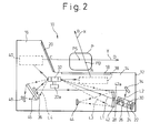
- FIGS 1 and 2 are exemplary diagrams illustrating an optical scanner, such as a bar code reader, according to one embodiment of the present invention.
- the optical scanner 10 includes a body 12, a base portion 14 and a cover portion 16.
- a bottom reading window 18 is provided in the surface of the base portion 14, and a side reading window 20 is provided in the surface of the cover portion 16.
- the bottom reading window 18 and the side reading window 20 are placed at an angle with respect to each other, forming essentially an "L" shape.
- a light beam emitted from the bottom reading window 18 is designated by an arrow X
- another light beam emitted from the side reading window 20 is designated by an arrow Y.
- An optimum reading zone (region P) extends over the bottom reading window 18 and has a center at a predetermined distance from the side reading window 20. Hence, when an object is in the optimum reading zone (region P), a commodity with a bar code attached can be read optimally. In addition, even if the commodity, or object, is outside of the optimum reading zone P, a bar code attached thereto can be read, but may not be read successfully.
- the optical scanner 10 includes a light source (such as a laser diode) 22, a first beam shaping device 24, a light splitting member 26, and a second beam shaping device 28. These members are attached to a common frame and comprise a single unit designated as light source module 30.
- the optical scanner 10 further includes a polygon mirror 32, which is rotated by a motor 32a, and two mirrors 34 and 36.
- the light source module 30 is located near a lower end of the base portion 14 towards the rightmost end portion of the main body 12 as viewed in Figure 2.
- the mirror 34 is located above the light source module 30 which is at one end of the base portion 14, and the mirror 36 is located near the other end of the base portion 14.
- the polygon mirror 32 is located in the vicinity of the leftmost portion of the main body 12, between the reading windows 18 and 20.
- Examples of light splitting member 26 include a half mirror, a half-cube beam splitter, or a polarization beam splitter.
- Light splitting member 26 splits a light beam emitted from the light source 22 into a first light beam component traveling along a first optical path L1, and a second light beam component traveling along a second optical path L2.
- the first light beam component L1 is transmitted through the light splitting member 26, and travels in a straight line to one side of the polygon mirror 32.
- the second light beam component L2 is reflected by the light splitting member 26 and transmitted first to mirror 34 and then reflected to mirror 36 so that the optical path from light splitting member 26 to the other side of polygon mirror 32 is bent.
- Mirror 36 reflects the second light beam component L2 to the other side of polygon mirrcr 32.
- the second light beam component L2 when reflected between mirrors 34 and 36, travels along a path located under the polygon mirror 32.
- the first light beam component L1 reflected by the polygon mirror 32 is emitted from the bottom reading window 18 through the group of bottom mirrors 38 as, for example, a light beam X which scans an object.
- the second light beam component L2 is emitted from the side reading window 20 through a group of mirrors 40 as, for example, a light beam Y which then scans the object.
- the object In order for an object to be scanned by the light beams X and Y, the object must pass through a space zone referred to as an optimum reading zone.
- This optimum reading zone which extends over the bottom reading window 18, and has a center at a predetermined distance from the side reading window 20, is defined in Figure 2 as region P.
- An object to be scanned, including, for example, a bar code, passing through region P can then be optimally read. If the object passes outside the optimum region P, the bar code can still be read, however, the accuracy with which the bar code can be read is substantially reduced.
- the light beams X and Y scan and are reflected off of the object in scattered directions.
- the reflected, scattered light re-enters the bottom reading window 18 and the side reading window 20.
- the reflected, scattered light re-entering the reading window 18 is then reflected by one side of polygon mirror 32, as illustrated by L3.
- the reflected, scattered light re-entering the side window 20 is then reflected by the other side of polygon mirror 32, as illustrated by L4.
- a reflecting mirror 42 is placed near the light source module 30 in the optical path of the first light beam component L1.
- the reflecting mirror 42 is formed as a concave mirror, having a hole 42a bored in the central portion.
- the hole 42a permits the first light beam component L1, which is transmitted to the polygon mirror 32 from the light splitting member 26, to pass therethrough.
- a first detector 44 is placed at the focal point of the reflecting mirror 42.
- the reflected light beam L3 upon re-entering the reading window 18, impinges upon a large area of the surface of the reflecting mirror 42, and is condensed and incident to the first detector 44.
- the first detector 44 for example a pin photodiode, operates to convert the quantity of detected light into an electric signal. This electric signal is sent to an electric circuit (not shown), in which demodulation or the like is performed thereon.
- an electric circuit not shown
- a collector 46 larger in size than the mirror 36, is placed on the rear side of the mirror 36.
- the collector 46 comprises, for example, a convex lens or Freshel lens.
- a second detector 48 is placed at the focal point of the collector 46 to detect the reflected light beam L4 which passes through and is condensed by the collector 46.
- the second detector 48 comprises, for example, a pin photodiode, and operates to convert the quantity of detected light into an electric signal.
- the electric signal is sent to an electric circuit (not shown), whereupon an object having, for example, a bar code attached thereto can be read.
- FIG. 3 illustrates an example of the first beam shaping device 24.
- the first beam shaping device 24 comprises a collimator lens 50 and an aperture 52, which are formed as a single unit serving as a module.
- the collimator lens 50 condenses divergent light beams emitted from the light source (for example, a laser light source) 22 so that the light beams are made to be slightly convergent in comparison with parallel beams.
- the aperture 52 operates to cut off any extra part of the light beam passing through the collimator lens 50, further reducing the beam diameter.
- the diameter of the light beam emitted from the aperture 52 gradually decreases, until passing through a section S in which the light beam has a minimum beam diameter. After passing through section S, the beam diameter gradually begins to increase.
- Figure 4 is an exemplary graph illustrating the relationship between the.beam diameter of a light beam, having passed through the beam shaping device 24, and the distance from the light source 22.
- the distances a, b, c and d correspond to the positions A, B, C and D found in Figure 2. Namely, the distance a corresponds to the distance between the light source 22 and position A on the bottom reading window 18, the distance b corresponds to the distance from the light source 22 to position B on the optimum reading zone (region P) through the bottom reading window 18, the distance c corresponds to the position C on the side reading window 20, and the distance d corresponds to the distance between the light source 22 and the position D located across from the optimum reading zone (region P) through the side reading window 20.
- a bottom reading zone E is a region in which an object having a bar code attached thereto can be read by a light beam emitted from the bottom reading window 18.
- a side reading zone F is a region in which an object having a bar code attached thereto can be read by using a light beam emitted from the side reading window 20.
- the optimum reading zone (region P) is narrower than either the bottom reading zone E or the side reading zone F.
- the point PB corresponds to the distance between the light source 22 and the center of the optimum reading zone (region P) of Figure 2 in the direction along line AB.
- the point PS corresponds to the distance between the light source 22 and the center of the optimum reading zone (region P) of Figure 2 in the direction along line CD.
- the distance between the light source 22 and the point PB is shorter than the distance between the light source 22 and the point PS.
- the conventional scanner is set such that the point PS is the point at which light beam X has a minimum beam diameter.
- the position at which the light beam Y has a minimum beam diameter is not the point PS.
- the beam diameter at the point PS is slightly larger than the minimum beam diameter.
- the second beam shaping device 28 reduces the beam diameter of the light beam Y in the vicinity of the point PS.
- Figure 5 is an exemplary graph illustrating the characteristics of the first beam shaping device 24 and the second beam shaping device 28.
- Curve G represents the graph illustrated in Figure 4.
- Curve H represents the beam diameter when the setting of the first beam shaping device 24 is changed to decrease the beam diameter at the point PS, as described below.
- the beam diameter corresponding to the point PS on curve G is transferred to the beam diameter corresponding to the point PS' on curve H.
- the beam diameter of the light beam Y emitted from the side reading window 20, is reduced at the point PS.
- the beam diameter represented by curve H between points c and d is further reduced over that of curve G.
- the curve I represents the beam diameter when the setting of the second beam shaping device 28 is changed to decrease the beam diameter of the light beam X at the point PB.
- the beam diameter represented by curve I between points a and b is further reduced over that of curves G and H. Therefore, the beam diameter is decreased over the entire reading zone, allowing bar codes having a small width to be read using any of the light beams.
- the setting of the first beam shaping device 24 is changed to increase the distance between the light source 22 and the position of the focal point S at which the light beam has the minimum beam diameter. This is accomplished by increasing the focal length of the collimator lens 50 of the first beam shaping device 24 to a length greater than the length shown in Figure 4.
- curve G represents the case when the focal length of the collimator 50 is 3.6 mm
- the curve H represents the case when the focal length of the collimator 50 is 14 mm.
- the change in characteristics of the curve G to that represented by the curve H is attained by changing the diameter of the aperture 52, or by changing the distance between the light source 22 and the collimator lens 50.
- the second beam shaping device 28 is placed in the optical path of the first light beam component L1 as shown in Figure 2, and the point PB on curve G moves to the point PB' on curve H, as represented on the graph illustrated in Figure 5.
- the diameter of light beam X emitted from bottom reading window 18 is decreased.
- beam shaping is performed by second beam shaping device 28 only on the light beam X, and the beam diameter of the light beam emitted from the bottom reading window 18 is decreased.
- the focal length f of the plano-convex lens of the second beam shaping device 28 is 3000 mm. Since the focal length of the collimator lens 50 is 14 mm, the plano-convex lens of the second beam shaping device 28 for reducing the beam diameter of the light beam X at the point PS has a focal length which is hundreds of times as long as the focal length of the collimator lens 50.
- the focal point of the light beam component Y is adjusted to the optimum reading position.
- the focal point of the light beam component X which is collimated by the collimator lens 50, is set at a position whose distance from the light source is slightly shorter, by using the plano-convex lens.
- Figure 6 is an exemplary diagram illustrating modification of the first beam shaping device 24.
- the first beam shaping device 24 further includes a right-angle prism 54 between the collimator lens 50 and the aperture 52.
- the right-angle prism 54 is placed so that the oblique side of the right-angle prism 54 faces the aperture 52.
- the right-angle prism 54 may be placed so that the oblique side of the right-angle prism 54 faces the light source 22.
- other prisms may be employed.
- the divergence angle of one of the first and second light beam components is generally larger than the divergence angle of the other light beam component.
- the light beam is shaped by the right-angle prism 54 which reduces the larger divergence angle of the one of the light beam diameters to a value equal to the divergence angle of the other light beam diameter.
- the right-angle prism 54 reduces the beam diameter of the longitudinal light beam having a large divergence angle, but does not reduce the beam diameter of the transverse light beam having a small divergence angle.
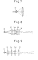
- Figure 8 is an exemplary diagram illustrating a cylindrical convex lens 54a and a cylindrical concave lens 54b, in place of the right-angle prism 54.
- the divergence angle of the longitudinal light beam which is indicated by solid lines and initially has a large divergence angle, can be made to be equal to the divergence angle of the transverse light beam which initially has a small divergence angle and is indicated by the dashed lines.
- a light source module 30 which includes the right-angle prism is shown and described with reference to Figures 26(A) - 26 (D) herein below.
- Figure 9 is an exemplary diagram showing a modification of the first beam shaping device 24 in another embodiment of the present invention.
- an example is provided with a cylindrical concave lens 54c and a cylindrical convex lens 54d, similar to the above example.
- the divergence angle of the transverse light beam which is indicated by the solid line and initially has a small divergence angle, is made to be equal with the divergence angle of the longitudinal light beam which initially has a large divergence angle and is indicated by dashed lines.
- Figures 10 and 11 are exemplary diagrams illustrating the placement of a group of the bottom mirrors 38 of Figure 2.
- the mirrors are illustrated so that the mirrors of Figure 2 are reversed from left to right.
- the group of the bottom mirrors 38 depicted in Figure 2 are placed just under the bottom reading window 18 of the base portion 14, the group of bottom mirrors 38 may be placed in other locations, such as in a lower part or a peripheral part of the base portion 14.
- Figure 10 illustrates that the base portion 14 of Figure 2 comprises of a lower frame 14a and an upper frame 14b.
- Figure 11 shows only the lower frame 14a of the base portion 14, but the upper frame 14b is mounted to the left-side part of the lower frame 14a.
- the cover portion 16 of Figure 2 is mounted to the right-side part of Figure 11.
- the polygon mirror 32 is shown in the central part of the lower frame 14 of Figure 10.
- a support base 32b is shown in the central part of the lower frame 14a of Figure 11.
- the polygon mirror 32 (not shown in Figure 11) is mounted to this support base 32b.
- the mirror 34 which receives a light beam reflected by the light splitting member 26 of Figure 2 is illustrated in the left end part of Figure 11.
- the light source module 30 of Figure 2 is placed below this mirror 34.
- the mirror 36 receiving a light beam reflected by the mirror 34 is shown in a right end part of Figure 11.
- the collector 46 of Figure 2 is shown in the rear of this mirror 36 as a Fresnel lens.
- the second detector 48 receiving reflected light condensed by the collector 46 is mounted on a printed circuit board 56.
- the first detector 44 is also mounted on the printed circuit board (not shown) which is placed in a "V-zone" of the left-end bottom portion of Figure 11.
- the lower frame 14a is also provided with mirrors ZB2, VBRR, VBLL, HBR2, HBL2, ZML2 and ZMR2. These mirrors comprise a part of the group of bottom mirrors 38.
- the lower frame 14a is also provided with the mirrors VSR1 and VSL1.
- Figure 10 depicts mirrors ZL and ZR attached to a cover (not shown). These mirrors comprise a part of the group of side mirrors 40. These mirrors are placed such that the reflecting faces thereof are directed nearly obliquely upwardly.
- the upper frame 14b is provided with mirrors ZBR1, ZBL1, HBR1, HBL1, VBR1, VBL1, VBR2, VBL2, ZMR1 and ZML1. These mirrors comprise a part of the group of bottom mirrors 38. These mirrors are placed such that the reflecting faces thereof are directed nearly obliquely downwardly.
- scanning is performed on the mirrors ZMR1, VBR2, VBR1, HBR1, ZBR1, ZBL1, HBL1, VBL1, VBL2 and ZML1, in this order.
- the light beam reflected by the mirrors of the upper frame 14b go to the mirrors of the lower frame 14a.
- the light beam reflected by the mirror ZMR1 is further reflected upwardly by the mirror ZMR2, and is then emitted from the bottom reading window 18.
- the light beam reflected by the mirrors VBR2 and VBR1 is further reflected by the mirror VBRR upwardly, and is then emitted from the bottom reading window 18, and so on.
- the cover portion includes a mirror holder 17, in which the mirrors VSL2, ZLL, ZHL, ZHR, ZRR, and VSR2 are mounted. These mirrors comprise a group of side mirrors 40.
- Figure 16 is an exemplary diagram illustrating another embodiment of the present invention.
- the embodiment shown in Figure 16 is similar to the embodiment of the present invention described herein above.
- the second beam shaping device 28 is located in a different place than the second beam shaping device 28 in the above-described first embodiment.
- the second beam shaping device 28 is formed as a plano-convex lens inserted in a hole 42a bored in the reflecting mirror 42.
- the hole 42a bored in the reflecting mirror 42 permits a first light beam component, which travels from the light splitting member 26 to the polygon mirror 32, to pass therethrough.
- the second beam shaping device 28 provided therein performs "beam-shaping".
- the second beam shaping device 28 formed in the hole 42a of the reflecting mirror 42 can be formed by a plano-convex lens which is similar to that of Figure 2. Therefore, the operation and advantageous effects of this second embodiment shown in Figure 16 are similar to those of the above-described first embodiment shown in Figure 2.
- Figure 17(A) is a perspective diagram showing the reflecting mirror 42, which is formed as a concave mirror as described with respect to Figure 2.
- Figure 17(B) is an exemplary plan diagram illustrating a modification of the reflecting mirror 42.
- a transmission type of hologram 43 having a concentric circular pattern is provided in a hole 42a bored in the reflecting mirror 42.
- a transmission type of hologram 43 condenses transmitted light.
- the hologram serves as the second beam shaping device 28, similar to the plano-convex lens in the first embodiment.
- the plano-convex lens and/or a hologram may be formed in such a manner as to be integral with the concave mirror 42 (not shown in Figure 17(B)). Further, the plano-convex lens and/or a hologram may be formed (or molded) separately from the concave mirror 42, and then fit into the scanner 10.
- Figure 18 is an exemplary diagram showing a modification of the reflecting mirror 42.
- the reflecting mirror 42 is formed as a plane mirror, and as a reflection type hologram having a concentric circular pattern.
- a light beam coming from the polygon mirror 32 is reflected toward the first detector 42 (see Figure 2) .
- a transmission hologram having a concentric circular pattern is provided in the hole 42a bored in the reflecting mirror 42. Therefore, the operation and advantageous effects of the example shown in Figure 18 are similar to the aforementioned embodiments of the present invention.
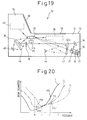
- Figure 19 is an exemplary diagram illustrating another embodiment of the present invention.
- the embodiment shown in Figure 19 has a configuration similar to the aforementioned embodiment of the present invention, except that the second beam shaping device 28 is located in a different place than in the first embodiment.
- the second beam shaping device 28 is formed as a concave lens 29.
- the concave lens 29 is placed between the mirrors 34 and 36 and reflects a light beam emitted from the light source 22 and reflected by the light splitting member 26 before reaching the polygon mirror 32.
- Figure 20 is an exemplary graph illustrating the effects of the first beam shaping device 24 and the second beam shaping device 28 depicted in Figure 19.
- curve G represents characteristics which are the same as Figure 4.
- Curve J represents the first beam shaping device 24 changed to decrease the beam diameter at the point PB.
- the distance between the light source 22 and the point S (at which the beam has a minimum beam diameter) must be decreased by changing the setting of the first beam shaping device 24 to reduce the focal length f of the collimator lens 50.
- a change in the characteristics from those represented by the curve G to those represented by the curve J can be achieved by changing the hole size of the aperture 52 or the distance between the light source 22 and the collimator lens 50. Consequentiy, the point PS on the curve G moves to the point PS' on the curve J. Thus the beam diameter of the light beam at the point PS is increased.
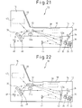
- Figure 21 is an exemplary diagram illustrating another embodiment of the present invention.
- the embodiment shown in Figure 21 has a configuration similar to the aforementioned embodiment, except that the second beam shaping device 28 is located in a different place than that of the previously discussed embodiment.
- the second beam shaping device 28 is formed as a mirror 34 reflecting a light beam emitted from the light source 22 and reflected by the light splitting member 26 to the mirror 34.
- Mirror 34 is formed as a concave mirror. Consequently, advantageous effects similar to those of Figure 19 are attained by the present embodiment.
- Figure 22 is an exemplary diagram showing an embodiment of the present invention similar to the embodiment illustrated in Figure 21.
- the second beam shaping device 28 is formed as a mirror 36 reflecting a light beam emitted from the light source 22 then reflected by the light splitting member 26 to the polygon mirror 32 through the mirror 34. Consequently, advantageous effects similar to those of the embodiment of the present invention illustrated in Figure 19 are obtained.
- Figure 23 is an exemplary diagram showing another embodiment of the present invention similar to that shown in Figure 22.
- the second beam shaping device 28 comprises the mirrors 34 and 36.
- One of the mirrors 34 and 36 is formed as a concave mirror, and the other is formed as a cylindrical lens.
- the mirror formed as a cylindrical lens, as described above with reference to Figures 8 and 9 are adapted to control the divergence angle of one of the light beams emitted from the laser light source 22, the divergence angles of which are different from one another.
- Figure 24 is an exemplary diagram showing an embodiment of the present invention similar to the embodiment illustrated in Figure 2.
- the second beam shaping device 28 is formed as a plano-convex lens 33, placed between the light splitting member 26 and the mirror 34.
- the operation and advantageous effects of this plano-convex lens 33 are the same as the plano-convex lens of Figure 2, serving as the second beam shaping device 28.
- the embodiment of Figure 24 is effective when the distance between the light source 22 and the bottom reading zone E is greater than the distance between the light source 22 and the side reading zone E.
- Figure 25 is an exemplary diagram showing another embodiment of the present invention.
- the optical scanner 10 includes the bottom reading window 18, the side reading window 20, and the common light source 22 used fcr these reading windows.
- the optical scanner 10 includes a single reading window 180.
- a light beam emitted from the common light source 22 is split into two light beam components by the light splitting member 26.
- An object is then scanned by the scanner 10 emitting the two light beam components from the reading window 180.
- the first beam shaping device 24 is located between the light source 22 and the light splitting member 26.
- the second beam shaping device 28 is located in one of the optical paths of the light beam components formed when the light beam is split by the light splitting device 26.
- the operation and advantageous effects of the first and second beam shaping devices 24 and 28 are similar to those of the aforementioned embodiments.
- Figures 26(A) and 26(B) are exemplary diagrams illustrating a light source module 30 including a right-angle prism.
- Figure 26(A) is a plan view of the light source module 30, and
- Figure 26(B) is a vertical cross-sectional diagram schematically illustrating the light source module 30.
- the light source module 34 includes a body 30a to which the light source 22 is attached,
- the collimator lens 50 of the first beam shaping device 24, the right-angle prism 54, the aperture 52 of the first beam shaping device 24, the light splitting means (half mirror) 26, and the second beam shaping device 28 are located in the body 30a of the light source module 30.
- the collimator lens 50 is attached to an aluminum block 50a and is then inserted into a hole bored in an end part of the body 30a, as shown in Figure 26(D).
- a lens serving as the second beam shaping device 28 is inserted into a hole bored in the other end part of the body 30a, as shown in Figure 26(C).
- the lens acting as the second beam shaping device 28 is shaped nearly like a semi-circle.
- the shape of a mounting hole 28a which is a groove having a U-shaped section, is matched with that of the same lens.
- the beam diameters of the two light beam components which are emitted from a common light source and split by an otpical beam splitter are minimized.
Abstract
Description
- The present invention relates in general to an optical scanner, and in particular to a method of, and device for, reducing the beam diameter of separate light beam components emitted from a common light source for an optical scanner.
- Point of Sale (POS) systems, such as optical scanners, capable of detecting and reading light reflected from a bar code attached to a commodity, are widely used. For example, optical scanners, which are also referred to as bar code readers, are used at "check-out" counters in grocery stores to scan a bar code attached to a commodity such as a food product. By manipulating the commodity, these optical scanner systems provide an operator, such as a cashier, using the system to reduce the amount of time it takes to "scan" information about the commodity, reducing the burden on the operator and increasing the operator's efficiency.
- In recent years, optical scanners with two reading windows have been developed. The two windows are provided, for example, in the bottom and front portions of the optical scanner, forming an "L" shape. The two windows enable the optical scanner to read and scan from multiple directions bar codes attached to commodities. Hence, a bar code attached to a commodity may be detected and read from light sources emitting from both windows, despite differing orientations of the bar code on the commodity. This feature further lightens the burden imposed on the operator. However, such optical scanners with multiple windows require separate optical scanners for each window. The result is a costly, complex optical scanner with numerous parts, which is large in size.
- For example, optical scanners which have reading windows respectively provided in both the bottom and front portions thereof require optical scanning systems for each of the reading windows. Each of the optical scanning systems includes a light source, scanning means such as a polygon mirror, and other mirrors. Thus, the scanner is complex and requires a large number of components or parts, which increases the manufacturing costs. However, if a common light source is used for both of the optical scanning systems, the required number of parts and the costs associated therewith decrease.
- The use of a
common light source 1 in anoptical scanner 100 is shown in Figure 27 of the accompanying drawings. Figure 27 is an exemplary diagram illustrating a previously-proposedoptical scanner 100 with acommon light source 1 and used, for example, to scan a bar code attached to an object. To use acommon light source 1 in theoptical scanner 100 shown in Figure 27, alight splitting device 2, such as a half mirror (semi-transparent mirror), is used to split acommon light source 1 into a first light beam component X and a second light beam component Y. The first and second light beam components X and Y, respectively, are then directed to acommon polygon mirror 3, either directly or through another mirror. Light beam component X is then emitted through a group of mirrors M1 from reading window 4 (provided in the bottom portion of the optical scanner 100), and light beam component Y is emitted through a group of mirrors M2 from reading window 5 (provided in the front portion of the optical scanner 100). The emitted light beam components X and Y then impinge on, for example, a bar code attached to an object passing through the emitted light, which reflects back to theoptical scanner 100. The bar code is read by theoptical scanner 100 by detecting the reflectedlight using detectors - In order to read more accurately a bar code, and in particular, a bar code with narrow spaces between adjacent bars, the beam width of the light beam scanning the bar code must be sufficiently reduced. To reduce the beam width of the light beam scanning the bar code, for example, light beam components X and Y (shown in Figure 27), a
beam shaping device 8 is placed between thecommon light source 1 and thelight splitting device 2. Moreover, it is also necessary not only to reduce the diameter of the light beam components X and Y, but to reduce the diameter at a desired position. That is, the diameter of the beam size must be sufficiently reduced at the desired position, particularly the position where the object is being scanned. - As the width of the bars in the bar code narrows, it becomes increasingly difficult for an emitted light source to read the bar code. A desirable solution to reading bar codes with narrow spaces between bars would be to use a
common light source 1 having a smaller diameter. As discussed above, it is desirable to "split" the common light source 1 (i.e. laser beam) into first and second laser beam components X and Y, such that the bar code may be read or scanned from multiple directions (from a bottom portion and a front portion of the optical scanning device). Using the first and second laser beam components X and Y, respectively, an "optimum reading zone" is established by defining first and second focal points of the first and second laser beam components X and Y, respectively. It is desirable that the focal point (a point at which the laser beam has the smallest diameter) of the laser beam is established near the (reading) center of the optimum reading zone. In this regard, thecommon light source 1 is able to read and scan the bar code with increasing efficiency when the two focal points are directed towards the same location. To accomplish this, it is desirable that the distance from the light source, from which the scanning light (light beam component X in Figure 27) is emitted from thebottom reading window 4, to the reading center is equal to the distance from the light source, from which the scanning light (light beam component Y in Figure 27) is emitted from theside reading window 5, to the reading center. - However, due to the complexity of the optical components in such a previously-proposed optical scanner, it is difficult to equalize these distances and may result in the focal point of the first light beam component X being set at the center of the cptical reading zone, and the focal point of the second light beam component Y being set off-center of the optimal reading zone. In that case, the bar code cannot be read using the second scanning light. Hence, achieving optimal first and second focal points is hindered, resulting in the failure of one of the laser beam components from reading or scanning the bar code as it passes through the "optimum reading zone".
- According to a first aspect of the present invention there is provided an optical scanner including: a body; at least one reading window provided in the body; a light source provided in the body; a light splitting device for splitting a light beam emitted from the light source into a first light beam component travelling along a first optical path and a second light beam component travelling along a second optical path; a light scan device for allowing the first light beam component and the second light beam component to be emitted from the reading window; a first beam shaping device placed between the light source and the light splitting device; and a second beam shaping device placed in one of the first and second optical paths.
- According to a second aspect of the present invention there is provided an optical scanner including:a body; a first reading window provided in the body; a second reading window provided in the body at an angle with the first reading window; a light source; a light splitting device for splitting a light beam emitted from the light source into a first light beam component travelling along a first optical path and a second light beam component travelling along a second optical path; a light scan device allowing the first light beam component and the second light beam component split by the light splitting device to be emitted from the first reading window and the second reading window; at least one detector detecting the light beam which is emitted from the reading windows and impinges on and is reflected by an object; a first beam shaping device placed between the light source and the light splitting device; and a second beam shaping device placed in one of the first and second optical paths.
- Thus, an optical scanner can be provided which reduces the beam diameters of two light beam components into which a light beam emitted from a common light source is split by an optical beam splitter.
- Moreover, an optical scanner can be provided which is provided with a common light source and two reading windows, and which can read a bar code with good sensitivity by using light beams respectively emitted from the reading windows.
- In particular, in an embodiment of the present invention, a light beam emitted from the light source is shaped by the first beam shaping device in such a manner as to have a reduced beam diameter at a desired position. However, in some cases, each of the two light beam components split by the light splitting device does not have a minimum beam diameter at a desirable position. To solve this problem, the first beam shaping device reduces one of the two light beam components at a desired position, and the second beam shaping device is placed in the optical path of the other light beam component, correcting the position of the light beam to a desired position. Hence, each of the two light beam components split by the light splitting device has a minimum beam diameter at a desired position.
- In an embodiment of the present invention, the scan device may comprise a polygon mirror reflecting the first and second light beam components split by the light splitting device, at least one mirror placed between the light splitting device and the polygon mirror, a first group of mirrors causing the first light beam component reflected by the polygon mirror to be emitted from the first reading window, and a second group of mirrors causing the second light beam component reflected by the polygon mirror to be emitted from the second reading window.
- According to a third aspect of the present invention, there is provided an apparatus for scanning an object having a bar code attached thereto, the apparatus comprising a body including first and second reading windows emitting and receiving a light beam, a light splitting device splitting the beam of light emitted from a light source into first and second beam components, a light scan device for directing the first beam component and second beam component through the respective first and second reading windows, a first beam shaping device, a second beam shaping device, and a first and second detector for detecting the first and second beam components, respectively.
- According to a fourth aspect of the present invention, there is provided a light source module comprising a light source, first and second beam shaping means, and a light splitter splitting a light beam which is emitted from the light source. The first beam shaping means shapes a cross-sectional shape of the light beam and the second beam shaping means changes a focal distance of the light beam.
- According to a fifth aspect of the present invention, there is provided a light source module comprising a light source, a beam shaping device, and a light splitter splitting a light beam which is emitted from the light source into first and second light beams. The beam shaping device changes a focal position of one of the first and second light beams to a position in front of or beyond a focal position of the other one of the first and second light beams.
- In an embodiment of the present invention, the first beam shaping means reduces the light beam diameter at a first distance from the light source, and the second beam shaping means reduces the beam diameter of the light beam travelling along an optical path at a second distance from the light source which is different from the first distance.
- The first beam shaping means may include a collimator lens and an aperture.
- The second beam shaping means may comprise a convex lens whose focal length is greater than the collimator lens. Alternatively, the second beam shaping means may comprise a concave lens, or a concave mirror.
- The light source, the light splitting means and the first beam shaping means may be formed as one unit.
- Alternatively, the light source, the light splitting means, the first beam shaping means and the second beam shaping means may be formed as one unit.
- According to a sixth aspect of the present invention there is provided a method for scanning an object using an optical scanner, which method splits a light beam emitted from a light source, emits first and second beams respectively through first and second reading windows, scans the first and second beam components through the first and second reading windows such that the emitted light cross paths at an optical reading position, shapes the light beam and first or second beam components to minimize the diameter of the both the first and second beam components at the optical reading position, and detects the object.
- Reference will now be made, by way of example, to the accompanying drawings, in which:
- Figure 1 shows a perspective diagram of an optical scanner embodying the present invention;
- Figure 2 is a cross-sectional diagram schematically illustrating the internal structure of an optical scanner embodying the present invention;
- Figure 3 is an enlarged diagram showing a first beam shaping device of Figure 2;
- Figure 4 is an exemplary graph illustrating the relationship between the beam diameter of a light beam passing through the first beam shaping device and the distance from a light source;
- Figure 5 is an exemplary graph illustrating beam shaping performed by first and second beam shaping devices of Figure 2;
- Figure 6 is an exemplary diagram showing a modification of the first beam shaping device;
- Figure 7 is an exemplary diagram illustrating the divergence angle in the vertical direction of a light beam emitted from the light source different from the divergence angle in the transverse direction;
- Figure 8 is an exemplary diagram showing a modification of the first beam shaping device in another embodiment of the present invention;
- Figure 9 is an exemplary diagram showing a modification of the first beam shaping device in another embodiment of the present invention;
- Figure 10 is an exploded diagram showing the lower and upper frames of the body of the optical scanner, illustrating mirrors of a bottom mirror group;
- Figure 11 is an enlarged diagram showing the lower frame of Figure 7;
- Figure 12 is an exemplary diagram showing light beams emitted from the bottom reading window;
- Figure 13 is a partially cross-sectional diagram showing the lower and upper frames of the body of the optical scanner, illustrating mirrors of a side mirror group;
- Figure 14 is a perspective diagram showing mirrors mounted in a mirror frame placed in a cover;
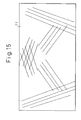
- Figure 15 is an exemplary diagram showing light beams emitted from the side reading window;
- Figure 16 is a cross-sectional diagram schematically illustrating the internal structure of the optical scanner of another embodiment of the present invention;
- Figures 17(A) and (B) are exemplary diagrams showing a reflecting mirror which includes the second beam shaping device of Figure 16;
- Figure 18 is an exemplary diagram showing another example of a modification of the reflecting mirror of Figure 17;
- Figure 19 is a cross-sectional diagram schematically illustrating the internal structure of another embodiment of an optical scanner embodying the present invention;
- Figure 20 is an exemplary graph illustrating the beam shaping performed by the first and second beam shaping devices of Figure 19;
- Figure 21 is a cross-sectional diagram schematically illustrating the internal structure of another optical scanner embodying the present invention;
- Figure 22 is a cross-sectional diagram schematically illustrating the internal structure of yet another optical scanner embodying the present invention;
- Figure 23 is a cross-sectional diagram schematically illustrating the internal structure of a further optical scanner embodying the present invention;
- Figure 24 is a cross-sectional diagram schematically illustrating the internal structure of still another optical scanner embodying the present invention;
- Figure 25 is a cross-sectional diagram schematically showing yet another optical scanner embodying the present invention;
- Figures 26(A) - (D) are exemplary diagrams showing a light source module; and
- Figure 27 is a diagram showing a previously-proposed optical scanner.
-
- In the drawings like numerals refer to like parts throughout.
- Figures 1 and 2 are exemplary diagrams illustrating an optical scanner, such as a bar code reader, according to one embodiment of the present invention. The
optical scanner 10 includes abody 12, abase portion 14 and acover portion 16. - A
bottom reading window 18 is provided in the surface of thebase portion 14, and aside reading window 20 is provided in the surface of thecover portion 16. Thebottom reading window 18 and theside reading window 20 are placed at an angle with respect to each other, forming essentially an "L" shape. - As shown in Figure 2, a light beam emitted from the
bottom reading window 18 is designated by an arrow X, and another light beam emitted from theside reading window 20 is designated by an arrow Y. An optimum reading zone (region P) extends over thebottom reading window 18 and has a center at a predetermined distance from theside reading window 20. Hence, when an object is in the optimum reading zone (region P), a commodity with a bar code attached can be read optimally. In addition, even if the commodity, or object, is outside of the optimum reading zone P, a bar code attached thereto can be read, but may not be read successfully. - Referring to Figure 2, the
optical scanner 10 includes a light source (such as a laser diode) 22, a firstbeam shaping device 24, alight splitting member 26, and a secondbeam shaping device 28. These members are attached to a common frame and comprise a single unit designated aslight source module 30. - The
optical scanner 10 further includes apolygon mirror 32, which is rotated by amotor 32a, and twomirrors light source module 30 is located near a lower end of thebase portion 14 towards the rightmost end portion of themain body 12 as viewed in Figure 2. Themirror 34 is located above thelight source module 30 which is at one end of thebase portion 14, and themirror 36 is located near the other end of thebase portion 14. Thepolygon mirror 32 is located in the vicinity of the leftmost portion of themain body 12, between the readingwindows - Examples of light splitting
member 26 include a half mirror, a half-cube beam splitter, or a polarization beam splitter.Light splitting member 26 splits a light beam emitted from thelight source 22 into a first light beam component traveling along a first optical path L1, and a second light beam component traveling along a second optical path L2. In the example of Figure 2, the first light beam component L1 is transmitted through thelight splitting member 26, and travels in a straight line to one side of thepolygon mirror 32. The second light beam component L2 is reflected by thelight splitting member 26 and transmitted first to mirror 34 and then reflected to mirror 36 so that the optical path from light splittingmember 26 to the other side ofpolygon mirror 32 is bent.Mirror 36 reflects the second light beam component L2 to the other side ofpolygon mirrcr 32. The second light beam component L2, when reflected betweenmirrors polygon mirror 32. - The first light beam component L1 reflected by the
polygon mirror 32 is emitted from thebottom reading window 18 through the group of bottom mirrors 38 as, for example, a light beam X which scans an object. The second light beam component L2 is emitted from theside reading window 20 through a group ofmirrors 40 as, for example, a light beam Y which then scans the object. In order for an object to be scanned by the light beams X and Y, the object must pass through a space zone referred to as an optimum reading zone. This optimum reading zone, which extends over thebottom reading window 18, and has a center at a predetermined distance from theside reading window 20, is defined in Figure 2 as region P. An object to be scanned, including, for example, a bar code, passing through region P can then be optimally read. If the object passes outside the optimum region P, the bar code can still be read, however, the accuracy with which the bar code can be read is substantially reduced. - More specifically, when an object is present in (or around) the optimum reading zone P, the light beams X and Y scan and are reflected off of the object in scattered directions. The reflected, scattered light re-enters the
bottom reading window 18 and theside reading window 20. The reflected, scattered light re-entering the readingwindow 18 is then reflected by one side ofpolygon mirror 32, as illustrated by L3. Similarly, the reflected, scattered light re-entering theside window 20 is then reflected by the other side ofpolygon mirror 32, as illustrated by L4. - To detect the reflected light, a reflecting
mirror 42 is placed near thelight source module 30 in the optical path of the first light beam component L1. The reflectingmirror 42 is formed as a concave mirror, having ahole 42a bored in the central portion. Thehole 42a permits the first light beam component L1, which is transmitted to thepolygon mirror 32 from thelight splitting member 26, to pass therethrough. Afirst detector 44 is placed at the focal point of the reflectingmirror 42. The reflected light beam L3 upon re-entering the readingwindow 18, impinges upon a large area of the surface of the reflectingmirror 42, and is condensed and incident to thefirst detector 44. Thefirst detector 44, for example a pin photodiode, operates to convert the quantity of detected light into an electric signal. This electric signal is sent to an electric circuit (not shown), in which demodulation or the like is performed thereon. Thus, for example, a bar code attached to an object is read. - A
collector 46, larger in size than themirror 36, is placed on the rear side of themirror 36. Thecollector 46 comprises, for example, a convex lens or Freshel lens. Asecond detector 48 is placed at the focal point of thecollector 46 to detect the reflected light beam L4 which passes through and is condensed by thecollector 46. Thesecond detector 48 comprises, for example, a pin photodiode, and operates to convert the quantity of detected light into an electric signal. The electric signal is sent to an electric circuit (not shown), whereupon an object having, for example, a bar code attached thereto can be read. - Figure 3 illustrates an example of the first
beam shaping device 24. The firstbeam shaping device 24 comprises acollimator lens 50 and anaperture 52, which are formed as a single unit serving as a module. Thecollimator lens 50 condenses divergent light beams emitted from the light source (for example, a laser light source) 22 so that the light beams are made to be slightly convergent in comparison with parallel beams. Theaperture 52 operates to cut off any extra part of the light beam passing through thecollimator lens 50, further reducing the beam diameter. In this regard, the diameter of the light beam emitted from theaperture 52 gradually decreases, until passing through a section S in which the light beam has a minimum beam diameter. After passing through section S, the beam diameter gradually begins to increase. - Figure 4 is an exemplary graph illustrating the relationship between the.beam diameter of a light beam, having passed through the
beam shaping device 24, and the distance from thelight source 22. The distances a, b, c and d correspond to the positions A, B, C and D found in Figure 2. Namely, the distance a corresponds to the distance between thelight source 22 and position A on thebottom reading window 18, the distance b corresponds to the distance from thelight source 22 to position B on the optimum reading zone (region P) through thebottom reading window 18, the distance c corresponds to the position C on theside reading window 20, and the distance d corresponds to the distance between thelight source 22 and the position D located across from the optimum reading zone (region P) through theside reading window 20. - Referring to Figure 4, a bottom reading zone E is a region in which an object having a bar code attached thereto can be read by a light beam emitted from the
bottom reading window 18. A side reading zone F is a region in which an object having a bar code attached thereto can be read by using a light beam emitted from theside reading window 20. The optimum reading zone (region P) is narrower than either the bottom reading zone E or the side reading zone F. The point PB corresponds to the distance between thelight source 22 and the center of the optimum reading zone (region P) of Figure 2 in the direction along line AB. Additionally, the point PS corresponds to the distance between thelight source 22 and the center of the optimum reading zone (region P) of Figure 2 in the direction along line CD. - As indicated from Figures 2 and 4, the distance between the
light source 22 and the point PB is shorter than the distance between thelight source 22 and the point PS. In such a case, the conventional scanner is set such that the point PS is the point at which light beam X has a minimum beam diameter. Hence, as described above, the position at which the light beam Y has a minimum beam diameter is not the point PS. As a result, the beam diameter at the point PS is slightly larger than the minimum beam diameter. When the pitch of the bars of a bar code is further reduced, it is preferable that scanning is performed using a light beam with a diameter further reduced. Hence, the secondbeam shaping device 28 reduces the beam diameter of the light beam Y in the vicinity of the point PS. - Figure 5 is an exemplary graph illustrating the characteristics of the first
beam shaping device 24 and the secondbeam shaping device 28. Curve G represents the graph illustrated in Figure 4. Curve H represents the beam diameter when the setting of the firstbeam shaping device 24 is changed to decrease the beam diameter at the point PS, as described below. Thus, the beam diameter corresponding to the point PS on curve G is transferred to the beam diameter corresponding to the point PS' on curve H. In particular, the beam diameter of the light beam Y, emitted from theside reading window 20, is reduced at the point PS. As a result, the beam diameter represented by curve H between points c and d is further reduced over that of curve G. Similarly, the curve I represents the beam diameter when the setting of the secondbeam shaping device 28 is changed to decrease the beam diameter of the light beam X at the point PB. The beam diameter represented by curve I between points a and b is further reduced over that of curves G and H. Therefore, the beam diameter is decreased over the entire reading zone, allowing bar codes having a small width to be read using any of the light beams. - To change the characteristics shown in curve G to those shown in curve H, and hence improve the performance of the optical scanner, the setting of the first
beam shaping device 24 is changed to increase the distance between thelight source 22 and the position of the focal point S at which the light beam has the minimum beam diameter. This is accomplished by increasing the focal length of thecollimator lens 50 of the firstbeam shaping device 24 to a length greater than the length shown in Figure 4. For example, curve G represents the case when the focal length of thecollimator 50 is 3.6 mm, and the curve H represents the case when the focal length of thecollimator 50 is 14 mm. The change in characteristics of the curve G to that represented by the curve H is attained by changing the diameter of theaperture 52, or by changing the distance between thelight source 22 and thecollimator lens 50. - However, a problem arises in that the point PB on curve G moves to the point PB' on curve H indicating that the beam diameter of-the light beam emitted from the
bottom reading window 18 is increased. To solve this problem, the secondbeam shaping device 28 is placed in the optical path of the first light beam component L1 as shown in Figure 2, and the point PB on curve G moves to the point PB' on curve H, as represented on the graph illustrated in Figure 5. As a result, the diameter of light beam X emitted frombottom reading window 18 is decreased. Hence, beam shaping is performed by secondbeam shaping device 28 only on the light beam X, and the beam diameter of the light beam emitted from thebottom reading window 18 is decreased. That is, when light beam X is emitted from readingwindow 18, the characteristics corresponding to the position of the focus is changed from that represented by curve H to that represented by curve I. Moreover, the beam diameter at the point PB' on the curve H is reduced to that at the point PB" on the curve I. - When the second
beam shaping device 28 is placed after thebeam splitter 26, the focal length f of the plano-convex lens of the secondbeam shaping device 28 is 3000 mm. Since the focal length of thecollimator lens 50 is 14 mm, the plano-convex lens of the secondbeam shaping device 28 for reducing the beam diameter of the light beam X at the point PS has a focal length which is hundreds of times as long as the focal length of thecollimator lens 50. - As a result, the beam diameters of the light beams X and Y emitted from the
bottom reading window 18 and theside reading window 20, respectively, are decreased. Scanning of an object can, therefore, be performed using the light beam with the smaller beam diameter. In the module of the embodiment of the present invention, the focal point of the light beam component Y is adjusted to the optimum reading position. The focal point of the light beam component X, which is collimated by thecollimator lens 50, is set at a position whose distance from the light source is slightly shorter, by using the plano-convex lens. - Figure 6 is an exemplary diagram illustrating modification of the first
beam shaping device 24. In this example, the firstbeam shaping device 24 further includes a right-angle prism 54 between thecollimator lens 50 and theaperture 52. The right-angle prism 54 is placed so that the oblique side of the right-angle prism 54 faces theaperture 52. However, the right-angle prism 54 may be placed so that the oblique side of the right-angle prism 54 faces thelight source 22. Moreover, instead of the right-angle prism 54, other prisms may be employed. - As illustrated in Figure 7, when a light beam is emitted from the
laser diode 22, the divergence angle of one of the first and second light beam components, which are orthogonal to each other, is generally larger than the divergence angle of the other light beam component. The light beam is shaped by the right-angle prism 54 which reduces the larger divergence angle of the one of the light beam diameters to a value equal to the divergence angle of the other light beam diameter. For example, the right-angle prism 54 reduces the beam diameter of the longitudinal light beam having a large divergence angle, but does not reduce the beam diameter of the transverse light beam having a small divergence angle. - Figure 8 is an exemplary diagram illustrating a cylindrical convex lens 54a and a cylindrical concave lens 54b, in place of the right-
angle prism 54. In this example, the divergence angle of the longitudinal light beam, which is indicated by solid lines and initially has a large divergence angle, can be made to be equal to the divergence angle of the transverse light beam which initially has a small divergence angle and is indicated by the dashed lines. - A
light source module 30 which includes the right-angle prism is shown and described with reference to Figures 26(A) - 26 (D) herein below. - Figure 9 is an exemplary diagram showing a modification of the first
beam shaping device 24 in another embodiment of the present invention. Referring to Figure 9, an example is provided with a cylindricalconcave lens 54c and a cylindricalconvex lens 54d, similar to the above example. In this case, the divergence angle of the transverse light beam, which is indicated by the solid line and initially has a small divergence angle, is made to be equal with the divergence angle of the longitudinal light beam which initially has a large divergence angle and is indicated by dashed lines. - Figures 10 and 11 are exemplary diagrams illustrating the placement of a group of the bottom mirrors 38 of Figure 2. In Figures 10 and 11, the mirrors are illustrated so that the mirrors of Figure 2 are reversed from left to right. Although the group of the bottom mirrors 38 depicted in Figure 2 are placed just under the
bottom reading window 18 of thebase portion 14, the group of bottom mirrors 38 may be placed in other locations, such as in a lower part or a peripheral part of thebase portion 14. - More specifically, Figure 10 illustrates that the
base portion 14 of Figure 2 comprises of alower frame 14a and an upper frame 14b. Figure 11 shows only thelower frame 14a of thebase portion 14, but the upper frame 14b is mounted to the left-side part of thelower frame 14a. Thecover portion 16 of Figure 2 is mounted to the right-side part of Figure 11. - The
polygon mirror 32 is shown in the central part of thelower frame 14 of Figure 10. Asupport base 32b is shown in the central part of thelower frame 14a of Figure 11. The polygon mirror 32 (not shown in Figure 11) is mounted to thissupport base 32b. Additionally, themirror 34 which receives a light beam reflected by thelight splitting member 26 of Figure 2 is illustrated in the left end part of Figure 11. Thelight source module 30 of Figure 2 is placed below thismirror 34. Themirror 36 receiving a light beam reflected by themirror 34 is shown in a right end part of Figure 11. Thecollector 46 of Figure 2 is shown in the rear of thismirror 36 as a Fresnel lens. Thesecond detector 48 receiving reflected light condensed by thecollector 46 is mounted on a printedcircuit board 56. Thefirst detector 44 is also mounted on the printed circuit board (not shown) which is placed in a "V-zone" of the left-end bottom portion of Figure 11. - As shown in Figures 10 and 11, the
lower frame 14a is also provided with mirrors ZB2, VBRR, VBLL, HBR2, HBL2, ZML2 and ZMR2. These mirrors comprise a part of the group of bottom mirrors 38. Thelower frame 14a is also provided with the mirrors VSR1 and VSL1. Figure 10 depicts mirrors ZL and ZR attached to a cover (not shown). These mirrors comprise a part of the group of side mirrors 40. These mirrors are placed such that the reflecting faces thereof are directed nearly obliquely upwardly. - The upper frame 14b is provided with mirrors ZBR1, ZBL1, HBR1, HBL1, VBR1, VBL1, VBR2, VBL2, ZMR1 and ZML1. These mirrors comprise a part of the group of bottom mirrors 38. These mirrors are placed such that the reflecting faces thereof are directed nearly obliquely downwardly.
- A light beam emitted from the
light source 22, transmitted by thelight splitting member 26, is reflected by thepolygon mirror 32, and is incident to the mirrors of theupper frame 14. When, however, thepolygon mirror 32 is rotated clockwise, scanning is performed on the mirrors ZMR1, VBR2, VBR1, HBR1, ZBR1, ZBL1, HBL1, VBL1, VBL2 and ZML1, in this order. The light beam reflected by the mirrors of the upper frame 14b go to the mirrors of thelower frame 14a. For example, the light beam reflected by the mirror ZMR1 is further reflected upwardly by the mirror ZMR2, and is then emitted from thebottom reading window 18. The light beam reflected by the mirrors VBR2 and VBR1 is further reflected by the mirror VBRR upwardly, and is then emitted from thebottom reading window 18, and so on. - As à result, as illustrated in Figure 12, light beams are emitted from the
bottom reading window 18 in various directions and angles. Thus, an object can be scanned in various directions, angles, and orientations. An arrow X in Figure 2 indicates a light beam emitted from thebottom reading window 18 of theoptical scanner 10, which, after impinging upon an object, is detected byfirst detector 44. Additionally, as shown in Figures 13 and 14, the cover portion includes amirror holder 17, in which the mirrors VSL2, ZLL, ZHL, ZHR, ZRR, and VSR2 are mounted. These mirrors comprise a group of side mirrors 40. - Regarding the
group 40 of side mirrors, a light beam which is emitted from thelight source 22 and is reflected by thelight splitting member 26, travels toward thepolygon mirror 32. Then, the light beam reflected by thepolygon mirror 32 is incident on the mirrors VSR1, VSL1, ZL and ZR of thelower frame 14a. Scanning is performed on the mirrors VSL1, ZL, ZR and VSR1, in this order. The light beam reflected by these mirrors then travels to the mirrors of themirror holder 17. Subsequently, the light beam reflected by the mirrors of themirror holder 17 is emitted from theside reading window 20. As shown in Figure 13, a mirror 47 is also placed between thecollector 46 and thesecond detector 48. Thus, a light beam having passed through thecollector 46 is reflected to the mirror 47, and is then incident on thesecond detector 48. - As illustrated in Figure 15, light beams, emitted from the
side reading window 20 in various directions and at diverse angles, scan an object. An arrow Y shown in Figure 2 indicates a typical one of these light beam. After having impinged on an object, the reflected light beam is detected bysecond detector 48. Therefore, unless a bar code is attached to an object directly upward, most bar codes can be read by using the light beams emitted from thebottom reading window 18 and theside reading window 20. - Figure 16 is an exemplary diagram illustrating another embodiment of the present invention. The embodiment shown in Figure 16 is similar to the embodiment of the present invention described herein above. However, in the embodiment of Figure 16, the second
beam shaping device 28 is located in a different place than the secondbeam shaping device 28 in the above-described first embodiment. In the embodiment of Figure 16, the secondbeam shaping device 28 is formed as a plano-convex lens inserted in ahole 42a bored in the reflectingmirror 42. Thehole 42a bored in the reflectingmirror 42 permits a first light beam component, which travels from thelight splitting member 26 to thepolygon mirror 32, to pass therethrough. Additionally, the secondbeam shaping device 28 provided therein performs "beam-shaping". The secondbeam shaping device 28 formed in thehole 42a of the reflectingmirror 42 can be formed by a plano-convex lens which is similar to that of Figure 2. Therefore, the operation and advantageous effects of this second embodiment shown in Figure 16 are similar to those of the above-described first embodiment shown in Figure 2. - Figure 17(A) is a perspective diagram showing the reflecting
mirror 42, which is formed as a concave mirror as described with respect to Figure 2. Figure 17(B) is an exemplary plan diagram illustrating a modification of the reflectingmirror 42. In ahole 42a bored in the reflectingmirror 42, a transmission type ofhologram 43 having a concentric circular pattern is provided. A transmission type ofhologram 43 condenses transmitted light. Thus, the hologram serves as the secondbeam shaping device 28, similar to the plano-convex lens in the first embodiment. The plano-convex lens and/or a hologram may be formed in such a manner as to be integral with the concave mirror 42 (not shown in Figure 17(B)). Further, the plano-convex lens and/or a hologram may be formed (or molded) separately from theconcave mirror 42, and then fit into thescanner 10. - Figure 18 is an exemplary diagram showing a modification of the reflecting
mirror 42. In the example of Figure 18, the reflectingmirror 42 is formed as a plane mirror, and as a reflection type hologram having a concentric circular pattern. Thus, a light beam coming from thepolygon mirror 32 is reflected toward the first detector 42 (see Figure 2) . A transmission hologram having a concentric circular pattern is provided in thehole 42a bored in the reflectingmirror 42. Therefore, the operation and advantageous effects of the example shown in Figure 18 are similar to the aforementioned embodiments of the present invention. - Figure 19 is an exemplary diagram illustrating another embodiment of the present invention. The embodiment shown in Figure 19 has a configuration similar to the aforementioned embodiment of the present invention, except that the second
beam shaping device 28 is located in a different place than in the first embodiment. In the embodiment of Figure 19, the secondbeam shaping device 28 is formed as aconcave lens 29. Theconcave lens 29 is placed between themirrors light source 22 and reflected by thelight splitting member 26 before reaching thepolygon mirror 32. - Figure 20 is an exemplary graph illustrating the effects of the first
beam shaping device 24 and the secondbeam shaping device 28 depicted in Figure 19. As in the example shown in Figure 5, curve G represents characteristics which are the same as Figure 4. Curve J represents the firstbeam shaping device 24 changed to decrease the beam diameter at the point PB. In order to change the characteristics represented by the curve G to those represented by the curve H, the distance between thelight source 22 and the point S (at which the beam has a minimum beam diameter) must be decreased by changing the setting of the firstbeam shaping device 24 to reduce the focal length f of thecollimator lens 50. - Additionally, a change in the characteristics from those represented by the curve G to those represented by the curve J can be achieved by changing the hole size of the
aperture 52 or the distance between thelight source 22 and thecollimator lens 50. Consequentiy, the point PS on the curve G moves to the point PS' on the curve J. Thus the beam diameter of the light beam at the point PS is increased. - On the other hand, as a result of using
concave lens 29, the beam diameter of the light beam at the point PS' is reduced to the beam diameter at the point PS". As shown in Figure 20, the characteristics are changed from those represented by the curve J to those represented by the curve K. Theconcave lens 29 has the effect of increasing the distance from thelight source 22 to the point S at which the light beam emitted from thelight source 22 has a minimum beam diameter. Consequently, this (third) embodiment of the present invention obtains advantageous effects similar to those of the embodiment of the present invention illustrated in Figure 2. - Figure 21 is an exemplary diagram illustrating another embodiment of the present invention. The embodiment shown in Figure 21 has a configuration similar to the aforementioned embodiment, except that the second
beam shaping device 28 is located in a different place than that of the previously discussed embodiment. In this (fourth) embodiment of the present invention, shown in Figure 21, the secondbeam shaping device 28 is formed as amirror 34 reflecting a light beam emitted from thelight source 22 and reflected by thelight splitting member 26 to themirror 34.Mirror 34 is formed as a concave mirror. Consequently, advantageous effects similar to those of Figure 19 are attained by the present embodiment. - Figure 22 is an exemplary diagram showing an embodiment of the present invention similar to the embodiment illustrated in Figure 21. In the embodiment of the present invention shown in Figure 22, the second
beam shaping device 28 is formed as amirror 36 reflecting a light beam emitted from thelight source 22 then reflected by thelight splitting member 26 to thepolygon mirror 32 through themirror 34. Consequently, advantageous effects similar to those of the embodiment of the present invention illustrated in Figure 19 are obtained. - Figure 23 is an exemplary diagram showing another embodiment of the present invention similar to that shown in Figure 22. In the embodiment of the present invention shown in Figure 23, the second
beam shaping device 28 comprises themirrors mirrors laser light source 22, the divergence angles of which are different from one another. - Figure 24 is an exemplary diagram showing an embodiment of the present invention similar to the embodiment illustrated in Figure 2. In the embodiment shown in Figure 24, the second
beam shaping device 28 is formed as a plano-convex lens 33, placed between thelight splitting member 26 and themirror 34. The operation and advantageous effects of this plano-convex lens 33 are the same as the plano-convex lens of Figure 2, serving as the secondbeam shaping device 28. In contrast with the embodiment of Figure 2, the embodiment of Figure 24 is effective when the distance between thelight source 22 and the bottom reading zone E is greater than the distance between thelight source 22 and the side reading zone E. - Figure 25 is an exemplary diagram showing another embodiment of the present invention. In the case of the aforementioned embodiments of the present invention, the
optical scanner 10 includes thebottom reading window 18, theside reading window 20, and thecommon light source 22 used fcr these reading windows. In contrast, in the embodiment of the present invention of Figure 25, theoptical scanner 10 includes asingle reading window 180. Additionally, a light beam emitted from thecommon light source 22 is split into two light beam components by thelight splitting member 26. An object is then scanned by thescanner 10 emitting the two light beam components from the readingwindow 180. The firstbeam shaping device 24 is located between thelight source 22 and thelight splitting member 26. The secondbeam shaping device 28 is located in one of the optical paths of the light beam components formed when the light beam is split by thelight splitting device 26. The operation and advantageous effects of the first and secondbeam shaping devices - Figures 26(A) and 26(B) are exemplary diagrams illustrating a
light source module 30 including a right-angle prism. Figure 26(A) is a plan view of thelight source module 30, and Figure 26(B) is a vertical cross-sectional diagram schematically illustrating thelight source module 30. Thelight source module 34 includes abody 30a to which thelight source 22 is attached, Thecollimator lens 50 of the firstbeam shaping device 24, the right-angle prism 54, theaperture 52 of the firstbeam shaping device 24, the light splitting means (half mirror) 26, and the secondbeam shaping device 28 are located in thebody 30a of thelight source module 30. Thecollimator lens 50 is attached to analuminum block 50a and is then inserted into a hole bored in an end part of thebody 30a, as shown in Figure 26(D). A lens serving as the secondbeam shaping device 28 is inserted into a hole bored in the other end part of thebody 30a, as shown in Figure 26(C). The lens acting as the secondbeam shaping device 28 is shaped nearly like a semi-circle. The shape of a mounting hole 28a, which is a groove having a U-shaped section, is matched with that of the same lens. - As described above, in an embodiment of the present invention, the beam diameters of the two light beam components which are emitted from a common light source and split by an otpical beam splitter are minimized.
- This application is based on, and claims priority from, Japanese Patent Application 9-208137, filed August 1, 1997 in Japan, which is incorporated herein by reference.
Claims (17)
- An optical scanner comprising:a light source for generating a light beam;a beam splitter for splitting the light beam into light beam components;beam shaping devices for shaping each of the light beam components; andmirrors for directing the light beam components to an optimal reading zone, wherein the beam shaping devices shape the light beam components to minimize the respective beam diameters at the optimal reading zone.
- An optical scanner, comprising:a body;at least one reading window provided in the body;a light source;light splitting means for splitting a light beam emitted from the light source into a first light beam component traveling along a first optical path and a second light beam component traveling along a second optical path;light scan means for allowing the first light beam component and the second light beam component split by the light splitting means to be emitted from the at least one reading window;first beam shaping means placed between the light source and the light splitting means; andsecond beam shaping means placed in one of the first and second optical paths.
- An optical scanner, comprising:a body;a first reading window provided in the body;a second reading window provided in the body at an angle with respect to the first reading window;a light source;light splitting means for splitting a light beam emitted from the light source into a first light beam component traveling along a first optical path and a second light beam component traveling along a second optical path;light scan means for allowing the first beam component and the second light beam component split by the light splitting means to be emitted from the first reading window and the second reading window;first beam shaping means placed between the light source and the light splitting means; andsecond beam shaping means placed in one of the first and second optical paths.
- The optical scanner according to claim 2 or 3, wherein the first beam shaping means is adapted to perform beam shaping so that a light beam emitted from the light source has a minimum beam diameter at a first distance from the light source, and the second beam shaping means is adapted to perform beam shaping so that the light beam component traveling along the one of the first and second optical paths has a minimum beam diameter at a second distance from the light source, which is different than the first distance.
- The optical scanner according to claim 4, wherein the first beam shaping means comprises a collimator lens and an aperture.
- The optical scanner according to claim 5, wherein the second beam shaping means comprises a convex lens whose focal length is greater than that of the collimator lens.
- The optical scanner according to claim 4 or 5, wherein the second beam shaping means comprises a concave lens.
- The cptical scanner according to claim 4 or 5, wherein the second beam shaping means comprises a concave mirror.
- The optical scanner according to any preceding claim, wherein the light source, the light splitting means, and the first beam shaping means are formed as one unit.
- The optical scanner according to any one of claims 1 to 3, wherein the light source, the light splitting means, the first beam shaping means, and the second beam shaping means are formed as one unit.
- A light source module, comprising:a light source;first beam shaping means for shaping a light beam emitted from the light source;a light splitter for splitting a light beam, which is emitted from the light source into a first light beam, traveling along a first optical path, and a second light beam, traveling along a second optical path; andsecond beam shaping means placed in one of the first and second optical paths.
- An apparatus for scanning an object having a bar code attached thereto, comprising:a light source emitting a light beam;a light beam splitting device splitting the beam, of light emitted from the light source into a first light beam component and a second light beam component, the first light beam component traveling along a first optical path and the second light beam component traveling along a second optical path;a first reading window and a second reading window, each reading window emitting respective light beam components to impinge on and be reflected by the object and receiving the reflected light from the object;a light scan device directing the first light beam component and second light beam component through the first reading window and the second reading window, respectively, such that the first light beam component crosses paths with the second light beam component at an optimum reading position;a first beam shaping device, located between the light source and the light beam splitting device, minimizing the beam diameter of the first light beam component at the optimum reading position;a second beam shaping device, located in one of the first and second optical paths, minimizing the beam diameter of the second light beam component at the optimum reading position; anda detector system detecting the first and second beam components.
- The apparatus according to claim 12, wherein the detector system comprises:a first detector detecting the first beam component having been reflected back from the object; anda second detector detecting the second beam component having been reflected back from the object.
- A method for scanning an object using an optical scanner, comprising the steps of:splitting a light beam emitted from a light source into a first light beam component and a second light beam component, the first light beam component traveling along a first optical path and the second light beam traveling along a second optical path;scanning the first beam component and the second beam component to a first reading window and a second reading window, respectively, and emitting the first beam component and the second beam component therefrom such that the paths of the first and second light beam components which are emitted from the first and second reading windows, respectively, cross at an optimal reading position;shaping the light beam, to minimize the diameter of one of the light beam components at the optimal reading position, and shaping the other of the light beam components to minimize the diameter of the other of the light beam components at the optimal reading position; anddetecting the object when the first and second light beam components are reflected from the object.
- An optical scanner comprising:a light source module emitting light beam components of a light beam, said light beam components being shaped to minimize the beam diameters of the respective light beam components at an optimal reading zone; andmirrors directing the shaped light beam components to the optimal reading zone.
- A light source module, comprising:a light source;first beam shaping means for shaping a light beam emitted from the light source;a light splitter splitting a light beam, which is emitted from the light source into a first light beam, traveling along a first optical path, and a second light beam, traveling along a second optical path; andsecond beam shaping means placed in one of the first and second optical paths,wherein the first beam shaping means shapes a cross-sectional shape of the light beam and the second beam shaping means changes a focal distance of the light beam.
- A light source module, comprising:a light source;a light splitting device splitting a light beam, which is emitted from the light source, into a first light beam traveling along a first optical path and a second light beam traveling along a second optical path; anda beam shaping device, placed in one of the first and second optical paths, changing a focal position of one of the first and second light beams to a position in front of or beyond a focal position of the other one of the first and second light beams.
Applications Claiming Priority (3)
| Application Number | Priority Date | Filing Date | Title |
|---|---|---|---|
| JP208137/97 | 1997-08-01 | ||
| JP20813797A JP3580676B2 (en) | 1997-08-01 | 1997-08-01 | Optical scanning device and light source module |
| JP20813797 | 1997-08-01 |
Publications (3)
| Publication Number | Publication Date |
|---|---|
| EP0895176A2 true EP0895176A2 (en) | 1999-02-03 |
| EP0895176A3 EP0895176A3 (en) | 2001-12-19 |
| EP0895176B1 EP0895176B1 (en) | 2006-06-14 |
Family
ID=16551257
Family Applications (1)
| Application Number | Title | Priority Date | Filing Date |
|---|---|---|---|
| EP98303749A Expired - Lifetime EP0895176B1 (en) | 1997-08-01 | 1998-05-13 | Optical scanner and light source module |
Country Status (6)
| Country | Link |
|---|---|
| US (1) | US6469294B2 (en) |
| EP (1) | EP0895176B1 (en) |
| JP (1) | JP3580676B2 (en) |
| KR (1) | KR100444814B1 (en) |
| CN (1) | CN1162799C (en) |
| DE (1) | DE69834871T2 (en) |
Cited By (1)
| Publication number | Priority date | Publication date | Assignee | Title |
|---|---|---|---|---|
| EP1223535A2 (en) * | 2001-01-08 | 2002-07-17 | Symbol Technologies, Inc. | Bioptics bar code reader |
Families Citing this family (13)
| Publication number | Priority date | Publication date | Assignee | Title |
|---|---|---|---|---|
| US20030092023A1 (en) * | 1998-08-12 | 2003-05-15 | Daniel Dupret | Method of shuffling polynucleotides using templates |
| US6932271B2 (en) * | 2000-01-27 | 2005-08-23 | Ricoh Company, Ltd. | Optical scan module, optical scanner, optical scan method, image generator and image reader |
| DE60210010T2 (en) * | 2002-01-28 | 2006-10-12 | Fujifilm Electronic Imaging Ltd., Hemel Hempstead | Collimation system for laser diode |
| US7536271B2 (en) * | 2007-06-04 | 2009-05-19 | The Boeing Company | Methods and systems for manufacturing large components |
| US8740084B2 (en) * | 2009-11-12 | 2014-06-03 | Symbol Technologies, Inc. | Method and apparatus for projecting illumination patterns from barcode readers |
| US8496178B2 (en) * | 2011-08-31 | 2013-07-30 | Ncr Corporation | Method and apparatus for providing customer side imaging as well as bar code scanning imaging |
| US8757494B2 (en) * | 2011-09-27 | 2014-06-24 | Symbol Technologies, Inc. | Illumination system in imaging scanner |
| US9218516B2 (en) * | 2012-06-08 | 2015-12-22 | Datalogic ADC, Inc. | Data reader platter with integral features delineating a data-reading sweep region |
| USD723560S1 (en) * | 2013-07-03 | 2015-03-03 | Hand Held Products, Inc. | Scanner |
| CN103414834B (en) * | 2013-07-26 | 2016-01-20 | 深圳市顶星数码网络技术有限公司 | A kind of screen power-saving method, device and mobile terminal |
| USD730901S1 (en) * | 2014-06-24 | 2015-06-02 | Hand Held Products, Inc. | In-counter barcode scanner |
| CN105788108A (en) * | 2016-03-05 | 2016-07-20 | 福建联迪商用设备有限公司 | POS machine with function of scanning mirror two-dimensional code |
| US10802475B2 (en) * | 2018-07-16 | 2020-10-13 | Elite Robotics | Positioner for a robotic workcell |
Citations (5)
| Publication number | Priority date | Publication date | Assignee | Title |
|---|---|---|---|---|
| EP0691622A1 (en) * | 1994-06-30 | 1996-01-10 | Symbol Technologies, Inc. | Beam shaping for optical scanners |
| US5506392A (en) * | 1991-07-25 | 1996-04-09 | Symbol Technologies, Inc. | Photodetector for use in reading optical information symbols |
| EP0752680A1 (en) * | 1995-03-17 | 1997-01-08 | Symbol Technologies, Inc. | Optical scanners having dual surface optical elements for dual working ranges |
| EP0779591A2 (en) * | 1995-12-14 | 1997-06-18 | Fujitsu Limited | Bar code reader |
| US5646391A (en) * | 1995-05-11 | 1997-07-08 | Psc, Inc. | Optical assembly for controlling beam size in bar code scanners |
Family Cites Families (3)
| Publication number | Priority date | Publication date | Assignee | Title |
|---|---|---|---|---|
| US5194981A (en) * | 1988-10-21 | 1993-03-16 | Asahi Kogaku Kogyo Kabushiki Kaisha | Light scanning apparatus |
| US5206491A (en) * | 1990-03-02 | 1993-04-27 | Fujitsu Limited | Plural beam, plural window multi-direction bar code reading device |
| US5369284A (en) * | 1993-03-30 | 1994-11-29 | The Charles Stark Draper Laboratory, Inc. | Active edge position measuring device |
-
1997
- 1997-08-01 JP JP20813797A patent/JP3580676B2/en not_active Expired - Fee Related
-
1998
- 1998-03-20 US US09/045,044 patent/US6469294B2/en not_active Expired - Lifetime
- 1998-05-13 DE DE69834871T patent/DE69834871T2/en not_active Expired - Lifetime
- 1998-05-13 EP EP98303749A patent/EP0895176B1/en not_active Expired - Lifetime
- 1998-05-13 KR KR10-1998-0017156A patent/KR100444814B1/en not_active IP Right Cessation
- 1998-05-15 CN CNB981084451A patent/CN1162799C/en not_active Expired - Fee Related
Patent Citations (5)
| Publication number | Priority date | Publication date | Assignee | Title |
|---|---|---|---|---|
| US5506392A (en) * | 1991-07-25 | 1996-04-09 | Symbol Technologies, Inc. | Photodetector for use in reading optical information symbols |
| EP0691622A1 (en) * | 1994-06-30 | 1996-01-10 | Symbol Technologies, Inc. | Beam shaping for optical scanners |
| EP0752680A1 (en) * | 1995-03-17 | 1997-01-08 | Symbol Technologies, Inc. | Optical scanners having dual surface optical elements for dual working ranges |
| US5646391A (en) * | 1995-05-11 | 1997-07-08 | Psc, Inc. | Optical assembly for controlling beam size in bar code scanners |
| EP0779591A2 (en) * | 1995-12-14 | 1997-06-18 | Fujitsu Limited | Bar code reader |
Cited By (4)
| Publication number | Priority date | Publication date | Assignee | Title |
|---|---|---|---|---|
| EP1223535A2 (en) * | 2001-01-08 | 2002-07-17 | Symbol Technologies, Inc. | Bioptics bar code reader |
| EP1223535A3 (en) * | 2001-01-08 | 2003-01-08 | Symbol Technologies, Inc. | Bioptics bar code reader |
| AU781246B2 (en) * | 2001-01-08 | 2005-05-12 | Symbol Technologies, Inc. | Bioptics bar code reader |
| KR100832626B1 (en) * | 2001-01-08 | 2008-05-27 | 심볼테크놀로지스,인코포레이티드 | Bioptics bar code reader |
Also Published As
| Publication number | Publication date |
|---|---|
| JP3580676B2 (en) | 2004-10-27 |
| KR19990023129A (en) | 1999-03-25 |
| DE69834871T2 (en) | 2006-10-19 |
| EP0895176A3 (en) | 2001-12-19 |
| DE69834871D1 (en) | 2006-07-27 |
| EP0895176B1 (en) | 2006-06-14 |
| KR100444814B1 (en) | 2004-11-16 |
| US6469294B2 (en) | 2002-10-22 |
| CN1207538A (en) | 1999-02-10 |
| CN1162799C (en) | 2004-08-18 |
| JPH1153460A (en) | 1999-02-26 |
| US20010019104A1 (en) | 2001-09-06 |
Similar Documents
| Publication | Publication Date | Title |
|---|---|---|
| US5693930A (en) | Optical scanner having a plurality of scanning systems | |
| EP0895176B1 (en) | Optical scanner and light source module | |
| US5859417A (en) | Optical scanners having dual surface optical elements for dual working ranges | |
| EP0122126B1 (en) | Light-beam scanning apparatus | |
| US5206491A (en) | Plural beam, plural window multi-direction bar code reading device | |
| EP0752680B1 (en) | Optical scanners having dual surface optical elements for dual working ranges | |
| EP1367525A2 (en) | bar code reader | |
| EP0905641A1 (en) | Optical scanning apparatus | |
| US5179271A (en) | Compact optical scan pattern generator for bar code reading systems | |
| EP0396485A2 (en) | Bar code scanner with a large depth of field | |
| US5999301A (en) | Optical scanning device | |
| US6382513B1 (en) | Optical scanner with segmented collection mirror | |
| US7549584B2 (en) | Apparatus for optically reading identification information from commodity | |
| US7264167B2 (en) | Optical scanner having micro-electro-mechanical systems mirror array and associated method | |
| JP2810724B2 (en) | Bar code reader | |
| JP3866321B2 (en) | Optical scanner | |
| US8393543B2 (en) | Method and apparatus for scanning optical code | |
| JP2935464B2 (en) | Optical scanning device | |
| JPH02101595A (en) | Bar-code scanner | |
| JP2889754B2 (en) | Optical scanning device | |
| JPH06103392A (en) | Bar-code reader | |
| JP2987243B2 (en) | Optical scanning device | |
| JPH11110474A (en) | Bar code reading device | |
| JPH03172980A (en) | Bar code scanner | |
| JPH0534615A (en) | Laser bar-code scanner |
Legal Events
| Date | Code | Title | Description |
|---|---|---|---|
| PUAI | Public reference made under article 153(3) epc to a published international application that has entered the european phase |
Free format text: ORIGINAL CODE: 0009012 |
|
| AK | Designated contracting states |
Kind code of ref document: A2 Designated state(s): AT BE CH CY DE DK ES FI FR GB GR IE IT LI LU MC NL PT SE Kind code of ref document: A2 Designated state(s): DE FR GB |
|
| AX | Request for extension of the european patent |
Free format text: AL;LT;LV;MK;RO;SI |
|
| PUAL | Search report despatched |
Free format text: ORIGINAL CODE: 0009013 |
|
| AK | Designated contracting states |
Kind code of ref document: A3 Designated state(s): AT BE CH CY DE DK ES FI FR GB GR IE IT LI LU MC NL PT SE |
|
| AX | Request for extension of the european patent |
Free format text: AL;LT;LV;MK;RO;SI |
|
| 17P | Request for examination filed |
Effective date: 20020527 |
|
| AKX | Designation fees paid |
Free format text: DE FR GB |
|
| 17Q | First examination report despatched |
Effective date: 20050202 |
|
| GRAP | Despatch of communication of intention to grant a patent |
Free format text: ORIGINAL CODE: EPIDOSNIGR1 |
|
| GRAS | Grant fee paid |
Free format text: ORIGINAL CODE: EPIDOSNIGR3 |
|
| GRAA | (expected) grant |
Free format text: ORIGINAL CODE: 0009210 |
|
| AK | Designated contracting states |
Kind code of ref document: B1 Designated state(s): DE FR GB |
|
| REG | Reference to a national code |
Ref country code: GB Ref legal event code: FG4D |
|
| REF | Corresponds to: |
Ref document number: 69834871 Country of ref document: DE Date of ref document: 20060727 Kind code of ref document: P |
|
| ET | Fr: translation filed | ||
| PLBE | No opposition filed within time limit |
Free format text: ORIGINAL CODE: 0009261 |
|
| STAA | Information on the status of an ep patent application or granted ep patent |
Free format text: STATUS: NO OPPOSITION FILED WITHIN TIME LIMIT |
|
| 26N | No opposition filed |
Effective date: 20070315 |
|
| PGFP | Annual fee paid to national office [announced via postgrant information from national office to epo] |
Ref country code: GB Payment date: 20100329 Year of fee payment: 13 |
|
| PGFP | Annual fee paid to national office [announced via postgrant information from national office to epo] |
Ref country code: FR Payment date: 20100525 Year of fee payment: 13 |
|
| PGFP | Annual fee paid to national office [announced via postgrant information from national office to epo] |
Ref country code: DE Payment date: 20100512 Year of fee payment: 13 |
|
| REG | Reference to a national code |
Ref country code: DE Ref legal event code: R119 Ref document number: 69834871 Country of ref document: DE |
|
| REG | Reference to a national code |
Ref country code: DE Ref legal event code: R119 Ref document number: 69834871 Country of ref document: DE |
|
| GBPC | Gb: european patent ceased through non-payment of renewal fee |
Effective date: 20110513 |
|
| REG | Reference to a national code |
Ref country code: FR Ref legal event code: ST Effective date: 20120131 |
|
| PG25 | Lapsed in a contracting state [announced via postgrant information from national office to epo] |
Ref country code: FR Free format text: LAPSE BECAUSE OF NON-PAYMENT OF DUE FEES Effective date: 20110531 |
|
| PG25 | Lapsed in a contracting state [announced via postgrant information from national office to epo] |
Ref country code: GB Free format text: LAPSE BECAUSE OF NON-PAYMENT OF DUE FEES Effective date: 20110513 |
|
| PG25 | Lapsed in a contracting state [announced via postgrant information from national office to epo] |
Ref country code: DE Free format text: LAPSE BECAUSE OF NON-PAYMENT OF DUE FEES Effective date: 20111130 |