EP0895744A1 - Detektionseinrichtung für Filtereinrichtungen in Staubsaugern - Google Patents
Detektionseinrichtung für Filtereinrichtungen in Staubsaugern Download PDFInfo
- Publication number
- EP0895744A1 EP0895744A1 EP98113631A EP98113631A EP0895744A1 EP 0895744 A1 EP0895744 A1 EP 0895744A1 EP 98113631 A EP98113631 A EP 98113631A EP 98113631 A EP98113631 A EP 98113631A EP 0895744 A1 EP0895744 A1 EP 0895744A1
- Authority
- EP
- European Patent Office
- Prior art keywords
- filter
- detection device
- sensitive element
- vacuum cleaner
- sensor
- Prior art date
- Legal status (The legal status is an assumption and is not a legal conclusion. Google has not performed a legal analysis and makes no representation as to the accuracy of the status listed.)
- Granted
Links
Images

Classifications
-
- A—HUMAN NECESSITIES
- A47—FURNITURE; DOMESTIC ARTICLES OR APPLIANCES; COFFEE MILLS; SPICE MILLS; SUCTION CLEANERS IN GENERAL
- A47L—DOMESTIC WASHING OR CLEANING; SUCTION CLEANERS IN GENERAL
- A47L9/00—Details or accessories of suction cleaners, e.g. mechanical means for controlling the suction or for effecting pulsating action; Storing devices specially adapted to suction cleaners or parts thereof; Carrying-vehicles specially adapted for suction cleaners
- A47L9/10—Filters; Dust separators; Dust removal; Automatic exchange of filters
- A47L9/12—Dry filters
- A47L9/122—Dry filters flat
-
- A—HUMAN NECESSITIES
- A47—FURNITURE; DOMESTIC ARTICLES OR APPLIANCES; COFFEE MILLS; SPICE MILLS; SUCTION CLEANERS IN GENERAL
- A47L—DOMESTIC WASHING OR CLEANING; SUCTION CLEANERS IN GENERAL
- A47L9/00—Details or accessories of suction cleaners, e.g. mechanical means for controlling the suction or for effecting pulsating action; Storing devices specially adapted to suction cleaners or parts thereof; Carrying-vehicles specially adapted for suction cleaners
- A47L9/10—Filters; Dust separators; Dust removal; Automatic exchange of filters
- A47L9/14—Bags or the like; Rigid filtering receptacles; Attachment of, or closures for, bags or receptacles
- A47L9/1427—Means for mounting or attaching bags or filtering receptacles in suction cleaners; Adapters
- A47L9/1436—Connecting plates, e.g. collars, end closures
-
- A—HUMAN NECESSITIES
- A47—FURNITURE; DOMESTIC ARTICLES OR APPLIANCES; COFFEE MILLS; SPICE MILLS; SUCTION CLEANERS IN GENERAL
- A47L—DOMESTIC WASHING OR CLEANING; SUCTION CLEANERS IN GENERAL
- A47L9/00—Details or accessories of suction cleaners, e.g. mechanical means for controlling the suction or for effecting pulsating action; Storing devices specially adapted to suction cleaners or parts thereof; Carrying-vehicles specially adapted for suction cleaners
- A47L9/10—Filters; Dust separators; Dust removal; Automatic exchange of filters
- A47L9/14—Bags or the like; Rigid filtering receptacles; Attachment of, or closures for, bags or receptacles
- A47L9/1427—Means for mounting or attaching bags or filtering receptacles in suction cleaners; Adapters
- A47L9/1472—Means for mounting or attaching bags or filtering receptacles in suction cleaners; Adapters combined with security means, e.g. for preventing use, e.g. in case of absence of the bag
-
- A—HUMAN NECESSITIES
- A47—FURNITURE; DOMESTIC ARTICLES OR APPLIANCES; COFFEE MILLS; SPICE MILLS; SUCTION CLEANERS IN GENERAL
- A47L—DOMESTIC WASHING OR CLEANING; SUCTION CLEANERS IN GENERAL
- A47L9/00—Details or accessories of suction cleaners, e.g. mechanical means for controlling the suction or for effecting pulsating action; Storing devices specially adapted to suction cleaners or parts thereof; Carrying-vehicles specially adapted for suction cleaners
- A47L9/28—Installation of the electric equipment, e.g. adaptation or attachment to the suction cleaner; Controlling suction cleaners by electric means
- A47L9/2805—Parameters or conditions being sensed
-
- A—HUMAN NECESSITIES
- A47—FURNITURE; DOMESTIC ARTICLES OR APPLIANCES; COFFEE MILLS; SPICE MILLS; SUCTION CLEANERS IN GENERAL
- A47L—DOMESTIC WASHING OR CLEANING; SUCTION CLEANERS IN GENERAL
- A47L9/00—Details or accessories of suction cleaners, e.g. mechanical means for controlling the suction or for effecting pulsating action; Storing devices specially adapted to suction cleaners or parts thereof; Carrying-vehicles specially adapted for suction cleaners
- A47L9/28—Installation of the electric equipment, e.g. adaptation or attachment to the suction cleaner; Controlling suction cleaners by electric means
- A47L9/2836—Installation of the electric equipment, e.g. adaptation or attachment to the suction cleaner; Controlling suction cleaners by electric means characterised by the parts which are controlled
- A47L9/2842—Suction motors or blowers
-
- A—HUMAN NECESSITIES
- A47—FURNITURE; DOMESTIC ARTICLES OR APPLIANCES; COFFEE MILLS; SPICE MILLS; SUCTION CLEANERS IN GENERAL
- A47L—DOMESTIC WASHING OR CLEANING; SUCTION CLEANERS IN GENERAL
- A47L9/00—Details or accessories of suction cleaners, e.g. mechanical means for controlling the suction or for effecting pulsating action; Storing devices specially adapted to suction cleaners or parts thereof; Carrying-vehicles specially adapted for suction cleaners
- A47L9/28—Installation of the electric equipment, e.g. adaptation or attachment to the suction cleaner; Controlling suction cleaners by electric means
- A47L9/2894—Details related to signal transmission in suction cleaners
Definitions
- the invention relates to a detection device for filter devices in vacuum cleaners, in the next to a filter bag at least one additional filter can be used, with a feel the filter device inserted in the vacuum cleaner Sensor device and with those controlled by the sensor device Switching means for preventing the vacuum cleaner motor from being switched on if the filter device is not correctly recognized.
- the known detection devices make it possible switching on the motor when the filter bag is not inserted to prevent, however, there is a risk that a wrong additional filter is used, which also leads to malfunctions can lead.
- the detection device enables switching on of the vacuum cleaner if the additional filter is incorrect can be prevented, even if the incorrect one is used
- Auxiliary filter has a shape that that of the correct auxiliary filter corresponds. Becomes a poor quality or regarding the filter properties of inappropriate additional filters are used, who happens to have the same geometric design, for example, this can be an additional filter designed as a microfilter if the filtering is too coarse, the promised properties the vacuum cleaner does not meet, leading to complaints and complaints can lead. Also too little dust passage An incorrect, too tight additional filter can lead to impairments the vacuum cleaner function or even damage the vacuum cleaner motor to lead.
- the correct additional filter can be reliably recognized, so that the optimal vacuum cleaner function is maintained and Disadvantages due to coarse-pored or too fine-pored additional filters can be prevented.
- this detection device of course also an incorrectly inserted one correct additional filter or a missing additional filter detected become. Also in view of the ever stricter requirements the product liability of the invention proves Detection device as very advantageous.
- the sensor device can, of course, advantageously also in addition to sensing a sensitive element in or on the filter bag or the plate-like connector and to check the correct position and execution of the same be trained. This will protect the vacuum cleaner and the guarantee of a safe function still improved.
- the invention Detection device can be realized without structural changes compared to conventional vacuum cleaners or vacuum cleaner housings would be required.
- This unit can be easily and inexpensively in or on a Wall of the vacuum cleaner housing in the area of at least one sensitive element may be arranged, preferably with the wall of the vacuum cleaner housing provided essentially immediately next to the at least one sensitive one Element is arranged.
- the sensor device has for generating the electromagnetic waves advantageously at least one, in particular a transmitter having an oscillating circuit, the sensor signals from the repercussions of the sensitive element formed the transmitter and / or the electromagnetic waves become.
- the sensor device reacts very much sensitive to the shape and design of the sensitive element, so that the additional filter having this sensitive element or the so equipped connector of the respective Filter bag can be reliably recognized.
- this is sensitive Element designed as a metallic surface element, in particular as a metal plate or foil or layer, and
- the sensor signals are dependent on the eddy current effect caused attenuation of the transmitter.
- the Attaching such a metallic surface element to or in the additional filter and possibly also connector can be very inexpensive can be realized, in particular variations the respective surface and the respective shape in simpler Way are possible.
- the sensitive element in the evaluation device is used for evaluation expediently a certain amplitude of the vibration assigned to the resonant circuit, being used for detection in the Evaluation device is provided a threshold level a derived from the amplitude of the oscillation of the resonant circuit Signal is supplied, being above an adjustable first threshold value, switching on the vacuum cleaner motor Is blocked. From a certain area of the sensitive element, So from a certain damping onwards, the switch-on lock becomes canceled.
- An even more reliable detection of the correct additional filter or Filter bag is achieved by additionally below switching on a second adjustable lower threshold value of the vacuum cleaner motor is locked. This will For example, prevents an additional filter, which may be with a metal foil is covered or metallic components contains is recognized as correct.
- the sensitive Element means to send back to the received electromagnetic waves changed signals
- the Sensor device has a corresponding receiving device. This makes detection even more reliable reached.
- the frequency of the changed signals can be changed and / or phase position can be changed or they can Signal code included.
- corresponding Detection means for those who have changed in a certain way returned signals included.
- Such a sensitive element that increased requirements the technology provides is expedient as a microchip trained that easily for example between different Layers of the additional filter or connector are arranged can be mass-produced relatively inexpensively is.
- the transmitter can also as a light transmitter and the sensitive element as the light leading back to a light receiver in the sensor device Element be formed.
- Suitable as a sensitive element a barcode or the light unchanged or changed to a specific location in the sensor device return deflecting element.
- a capacitive can also be used as a further advantageous embodiment Detection of the sensitive element can be provided.
- a very Reliable detection of the correct additional filter or connector or filter bags are several sensitive Elements on or in the at least one additional filter and preferably also additionally on or in the connector and / or filter bag and are arranged by a corresponding Number of sensor sub-devices of the sensor device tactile.
- the at least one additional filter is preferably a microfilter and / or a filter cassette and / or an activated carbon filter and / or a combination filter as a combination of the above called filter. Only an additional filter can be used in the vacuum cleaner or several different additional filters are also provided be.
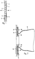
- the additional filter 1 shown schematically in FIG. 1 is, for example a microfilter and consists of a platelet-shaped Filter body made of a plastic fleece, plastic fabric or another filter material. Suitable as plastics for example polypropylene or polyester.
- a grid-like opening 3 is provided is covered by the additional filter 1.
- the wall 2 a recess corresponding to the shape of the additional filter 1 in which the additional filter 1 is held by tabs 4.
- the flexible additional filter 1 can be inserted into these tabs 4 become.
- other known mounting options are also available conceivable, such as elastic clamps, clamps, Screw fastenings, swivel fastenings or the like.
- the air sucked in by the vacuum cleaner first arrives in itself in a known manner in a filter bag 10, as for example is shown in Figure 2.
- the coarse dust and remains there the cleaned air passes through suitable, not shown Flow channels out of the vacuum cleaner housing outward.
- it passes through the microfilter Additional filter 11 through the fine impurities, such as Spores, germs, pollen and the like are retained to no allergies when blowing the air out of the vacuum cleaner or cause other impairments.
- a metal foil is on an edge area of the additional filter 1 attached as a sensitive element 5. Instead of a metal foil a metal plate or metallization can also occur.
- a metal plate or metallization can also occur on the opposite side of the additional filter 1 Wall 2 .
- a printed circuit board in the area of sensitive element 5 6 arranged on which an electronic circuit for Detection of the sensitive element 5 is arranged as in Figures 3 and 5 shown and described for example is.
- the sensitive element 5 can be used in particular in the case of a multilayer Execution of the additional filter 1 also between the layers, So be arranged inside the additional filter 1 and so on the one hand protected and on the other hand not recognizable from the outside arranged.
- a microfilter as an additional filter 1, for example an activated carbon filter or a filter cassette, which contains a pleated, lamellar filter material and is designed for example as an S-class filter. All of these filters can also be made in cardboard or plastic frames or housed in cardboard or plastic housings and for example be glued to them. It is also possible to use combination filters to use, i.e. for example a filter cassette with integrated activated carbon filter or a combined one Microfilter with activated carbon filter. The sensitive element can then either on the filter material itself or on the frame or Housing attached. It is also possible to have several such Arrange additional filters one after the other.
- the filter bag shown schematically in Figure 2 consists from the actual filter bag 10, the wall of one allowing air to pass through while retaining the dust in the bag Material is made, as well as from a connector 11, which on a location of the inlet opening actual filter bag 10 expediently by gluing is attached.
- a wall 12 of the Vacuum cleaner for which the filter bag is intended is an in the receiving space of the vacuum cleaner that receives the filter bag projecting connection piece 13 is present, on which the connector 11 when inserting the filter bag into the vacuum cleaner is plugged in so that the connecting piece 13 one on the connector 11 formed plug opening 14 passes through and in the inside of the filter bag protrudes. In this way, the Vacuum cleaner sucked air get into the filter bag which then leaves the dust filtered out on the filter bag wall.
- the connector 11 is substantially plate-shaped and consists of cardboard-like rigid material.
- a usually existing slide gate and a push-on opening 14 usually surrounding membrane seal are for Simplification not shown and with conventional filter bags also not available in every case.
- the connector 11 usually consists of several layers of cardboard, as for example in DE 43 39 298 is shown and described.
- a receiving groove for an edge region of the connector 11 provided retaining bar 15, which is also by two appropriately trained holding elements can be replaced.
- a locking projection 16 extends through the opposite side a locking opening 17 when plugging the connector 11 through and locks the connector 11. This can, for example also two locking projections 16 and two locking openings 17 may be provided.
- the type of attachment for the present invention is irrelevant and can, for example according to the state of the art already stated or according to DE 43 39 297 may be formed.
- a metal foil attached as a sensitive element 18 At the regarding the connector 11 opposite side of the wall 12 is corresponding 1 in the area of the sensitive element 18 Printed circuit board 19 arranged on the electronic circuit is arranged to detect the sensitive element 18. For this purpose, we also refer to the corresponding statements Figure 1 referenced.
- FIG. 3 In the embodiment shown as a block diagram in Figure 3 is an electromagnetic wave generating Oscillating circuit arrangement 20 via a rectification arrangement 21 connected to a comparator assembly 22 via which a triac 23 in the circuit of a vacuum cleaner motor 24 is controllable.
- the mode of operation consists in the fact that the resonant circuit of the resonant circuit arrangement 20 excited by an excitation switch (not shown) emits electromagnetic waves to the outside.
- the AC voltage signals generated due to the vibrations in the electronic circuit are rectified in the rectification arrangement 21, so that a signal is present at the output thereof which is dependent on the amplitude of the vibrations.
- the comparator arrangement 20 containing two comparators it is checked whether this signal is smaller than its first threshold value S 1 and at the same time larger than a second, lower threshold value S 2 . Only when these two conditions are met, the triac 23 is switched to conduct current, so that the vacuum cleaner motor 24 can be switched on by means of a manual switch (not shown).
- the first threshold value S 1 is set so that the output signal of the rectification arrangement 21 is higher when the resonant circuit arrangement 20 is not damped, so that the triac 23 is blocked.
- the sensitive element 5 or 18 comes into the effective range of the resonant circuit arrangement 20 and is induced by voltage in the sensitive element 5 or 18 Eddy currents are generated which withdraw energy from the resonant circuit and dampen it.
- the oscillation amplitude thereby decreases, so that the output signal of the rectification arrangement 21 also decreases.
- the two threshold values S 1 and S 2 are set so that the damping of the resonant circuit arrangement 20 generated by the sensitive element 5 or 18 in the correctly installed state of the additional filter 1 or connecting piece 11 is just sufficient to reduce the output signal of the rectification arrangement 21 below the upper one To press threshold S 1 , but not below the lower threshold S 2 so that the intended condition is met and the triac 23 is switched to the current-carrying state, so that the vacuum cleaner motor 24 can be switched on or operated.
- the threshold value S 1 would not be fallen below and the vacuum cleaner could not be operated.
- the comparator arrangement could 22 also have only one comparator, so that only checked is whether a sensitive element 5 or 18 with a certain Minimum size in or on the additional filter 1 or connector 11 is included.
- a triac 23 a other known electrical or electronic switches to step.
- the connector 11 is a schematic Shown top view.
- four different sensitive elements 25 - 28 arranged: three sensitive Elements 25 - 27 in a rectangular shape with different Areas and a sensitive element 28 in the form of a double stripe.
- these sensitive elements 25-28 Arrangement - with correctly inserted connector 11 - opposite are four resonant circuit arrangements on the circuit board 19 arranged the respective sensitive elements Scan or check 25 - 28.
- Each of the The resonant circuit arrangements 29-33 are thereby determined Damped way, the resonant circuit arrangement 33 no damping experiences. This is shown in comparator arrangements, not shown checked, and only if the intended damping value everywhere is detected, the triac 23 is turned on.
- the number and arrangement of the sensitive elements and resonant circuit arrangements can of course be chosen practically arbitrarily become.
- FIG. 4 An arrangement corresponding to FIG. 4 can of course be used also on one or, if available, on several additional filters 1 may be arranged, for example on a frame or housing an additional filter. The mode of action is then corresponding the description of FIG. 4.
- Circuit for checking a correct additional filter or filter bag or connector there is a sensor device from a transmitter 34 and a receiver 35 for electromagnetic Waves.
- One to be attached to the additional filter 1, for example sensitive element 36 is designed as a microchip and also consists of a receiver 37 and a transmitter 38 for electromagnetic waves.
- Power supply device 39 for the receiver 37 and the Transmitter 38 is provided, which is either designed as a battery or which are connected to the resonant circuit of the receiver 37 and the supply voltage from the RF energy received in the resonant circuit wins, as for example from DE 41 10 683 is known.
- a converter is contained in the receiver 37 or in the transmitter 38, by which the received signal is changed. This changed The signal is then transmitted by the transmitter 38 of the sensitive element 36 back to the receiver 35 of the sensor device.
- the conversion can be done, for example, by that the frequency or phase of the RF signal is changed.
- the retransmitted can Signal can be modulated in a certain way, so that a certain code sent to the receiver 35 of the sensor device becomes.
- the signal received in the receiver 35 is then in one Decoder 40 then checks whether the intended information of the sensitive element 36 is included. Is this the If so, the decoder 40 switches the triac 23 in a current-conducting manner. Further possibilities of signal coding and retransmission by sensitive elements 36 designed as microchips known from DE 41 10 683 already mentioned.
- the transmitter for electromagnetic waves as the light transmitter and the receiver trained as a light receiver for electromagnetic waves is.
- a barcode or another can then be used as a sensitive element Appear device that changes the light in or unchanged Way to the light receiver of the sensor device returns.
- a light guide can be provided, which on a Place light received by the sensor device on another Leads back to the additional filter or connector, on which the light receiver is arranged.
- the sensitive element in turn as a current-conducting plate or metallic surface element may be formed, the one Forms part of a capacitor of a resonant circuit.
- the sensor devices and evaluation devices can be integrated or non-integrated Circuits on the circuit board 6 and 19 may be included.
- the entire circuit fully or partially to form an integrated circuit or there can be several sensitive elements at different Make multiple circuit boards or other sensor devices be provided.
- a sensitive element or several sensitive elements arranged on the actual filter bag 10 be who usually clings to the walls during operation creates a filter bag space in the vacuum cleaner.
- the circuit board 19 and / or an integrated Sensor and evaluation circuit can be arranged. They are too combined versions possible, some of which are sensitive Elements on the actual filter bag 10 and some on the connector 11 are arranged. Of course, this applies also for additional filters.
Abstract
Description
- Figur 1
- in einer vereinfachten Darstellung ein an einem Gehäusebereich eines Staubsaugers angeordneter Zusatzfilter in einer Schnittdarstellung,
- Figur 2
- eine entsprechende Darstellung eines Filterbeutels,
- Figur 3
- ein Blockschaltbild eines ersten Ausführungsbeispiels mit einem als metallisches Flächenelement ausgebildeten sensitiven Elements,
- Figur 4
- eine Anordnung verschiedener solcher sensitiven Elemente auf einem Anschlußstück eines Zusatzfilters in der Draufsicht und
- Figur 5
- ein Blockschaltbild eines zweiten Ausführungsbeispiels der Erfindung, bei dem das sensitive Element die empfangenen elektromagnetischen Wellen in veränderter Form zurücksendet.
Claims (13)
- Detektionseinrichtung für Filtereinrichtungen in Staubsaugern, in die neben einem Filterbeutel noch wenigstens ein Zusatzfilter einsetzbar ist, mit einer die in den Staubsauger eingesetzte Filtereinrichtung abfühlenden Sensoreinrichtung und mit von der Sensoreinrichtung gesteuerten Schaltmitteln zur Verhinderung eines Einschaltens des Staubsaugermotors bei nicht korrekt erkannter Filtereinrichtung, dadurch gekennzeichnet, daß die wenigstens ein sensitives Element (5; 18; 25 - 28; 36) im oder am wenigstens einen Zusatzfilter (1) durch elektromagnetische Wellen abfühlende elektronische Sensoreinrichtung (20, 21; 34, 35) über eine anhand der Sensorsignale die korrekte Position und Ausführung des wenigstens einen sensitiven Elements (5; 18; 25 - 28; 36) prüfende Auswerteeinrichtung (22; 40) mit den Schaltmitteln (23) verbunden ist.
- Detektionseinrichtung nach Anspruch 1, dadurch gekennzeichnet, daß die Sensoreinrichtung (20, 21; 34, 35) zusätzlich zum Abfühlen eines sensitiven Elements (18) im oder am Filterbeutel (10) oder dessen plattenartigen Anschlußstück (11) und zur Prüfung der korrekten Position und Ausführung derselben ausgebildet ist.
- Detektionseinrichtung nach Anspruch 1 oder 2, dadurch gekennzeichnet, daß wenigstens die Sensoreinrichtung (20, 21; 34, 35) und die Auswerteeinrichtung (22; 40), vorzugsweise auch noch die Schaltmittel (23), als Baueinheit auf wenigstens einer Leiterplatte (6; 19) angeordnet und/oder als integrierter Schaltkreis ausgebildet sind.
- Detektionseinrichtung nach Anspruch 3, dadurch gekennzeichnet, daß die Baueinheit in oder an einer Wandung (2; 12) des Staubsaugergehäuses im Bereich insbesondere im wesentlichen unmittelbar neben des wenigstens einen sensitiven Elements (5; 18) angeordnet ist.
- Detektionseinrichtung nach einem der vorhergehenden Ansprüche, dadurch gekennzeichnet, daß die Sensoreinrichtung (20, 21; 34, 35) wenigstens einen die elektromagnetischen Wellen erzeugenden, insbesondere einen Schwingkreis aufweisenden Sender (20; 29 - 33; 35) besitzt, und daß die Sensorsignale aus den Rückwirkungen des sensitiven Elements (5; 18; 25 - 28; 36) auf den Sender (20; 29 - 33; 35) und/oder die elektromagnetischen Wellen gebildet werden.
- Detektionseinrichtung nach Anspruch 5, dadurch gekennzeichnet, daß das sensitive Element (5; 18; 25 - 28) als metallisches Flächenelement ausgebildet ist, insbesondere als Metallplatte oder -folie oder -schicht, und daß die Sensorsignale in Abhängigkeit der durch den Wirbelstromeffekt hervorgerufenen Dämpfung des Senders (20; 29 - 33) gebildet werden, wobei dem sensitiven Element (5; 18; 25 - 28) in der Auswerteeinrichtung (22) vorzugsweise eine bestimmte Amplitude der Schwingungen des Schwingkreises zugeordnet ist.
- Detektionseinrichtung nach Anspruch 6, dadurch gekennzeichnet, daß in der Auswerteeeinrichtung (22) eine Schwellwertstufe vorgesehen ist, der ein von der Amplitude der Schwingungen des Schwingkreises abgeleitetes Signal zugeführt ist, wobei oberhalb eines einstellbaren ersten Schwellwerts (S1) das Einschalten des Staubsaugermotors (24) gesperrt ist, wobei vorzugsweise zusätzlich unterhalb eines zweiten einstellbaren niedrigeren Schwellwerts (S2) das Einschalten des Staubsaugermotors (24) gesperrt ist.
- Detektionseinrichtung nach Anspruch 5, dadurch gekennzeichnet, daß das insbesondere als Mikrochip ausgebildete sensitive Element (36) Mittel (38) zum Rücksenden von gegenüber den empfangenen elektromagnetischen Wellen insbesondere in ihrer Frequenz und/oder Phasenlage veränderten Signalen aufweist und daß die Sensoreinrichtung (34, 35) eine entsprechende Empfangseinrichtung (35) besitzt, wobei die veränderten Signale vorzugsweise moduliert sind und/oder einen Signalcode enthalten.
- Detektionseinrichtung nach Anspruch 8, dadurch gekennzeichnet, daß die Auswerteeinrichtung (40) Erkennungsmittel für die in bestimmter Weise veränderten rückgesendeten Signale aufweist.
- Detektionseinrichtung nach Anspruch 5, dadurch gekennzeichnet, daß der Sender als Lichtsender und das sensitive Element als das Licht auf einen Lichtempfänger in der Sensoreinrichtung zurückführendes Element ausgebildet ist, wobei das sensitive Element vorzugsweise als Barcode oder als das Licht unverändert oder verändert zu einer bestimmten Stelle in der Sensoreinrichtung zurückführendes Umlenkelement ausgebildet ist.
- Detektionseinrichtung nach Anspruch 5, gekennzeichnet durch eine kapazitive Erfassung des sensitiven Elements.
- Detektionseinrichtung nach einem der vorhergehenden Ansprüche, dadurch gekennzeichnet, daß mehrere sensitive Elemente (25 - 28) an oder in dem wenigstens einen Zusatzfilter (1) und vorzugsweise auch an oder im Anschlußstück (11) und/oder Filterbeutel (10) angeordnet und durch Sensorteileinrichtungen (29 - 33) der Sensoreinrichtung abfühlbar sind.
- Detektionseinrichtung nach einem der vorhergehenden Ansprüche, dadurch gekennzeichnet, daß der wenigstens eine Zusatzfilter (1) ein Mikrofilter und/oder eine Filterkassette und/oder ein Aktivkohlefilter und/oder ein Kombinationsfilter ist.
Applications Claiming Priority (2)
| Application Number | Priority Date | Filing Date | Title |
|---|---|---|---|
| DE19734193A DE19734193A1 (de) | 1997-08-07 | 1997-08-07 | Detektionseinrichtung für Filtereinrichtungen in Staubsaugern |
| DE19734193 | 1997-08-07 |
Publications (2)
| Publication Number | Publication Date |
|---|---|
| EP0895744A1 true EP0895744A1 (de) | 1999-02-10 |
| EP0895744B1 EP0895744B1 (de) | 2003-08-27 |
Family
ID=7838258
Family Applications (1)
| Application Number | Title | Priority Date | Filing Date |
|---|---|---|---|
| EP98113631A Expired - Lifetime EP0895744B1 (de) | 1997-08-07 | 1998-07-22 | Detektionseinrichtung für Filtereinrichtungen in Staubsaugern |
Country Status (7)
| Country | Link |
|---|---|
| US (1) | US6073302A (de) |
| EP (1) | EP0895744B1 (de) |
| AT (1) | ATE247923T1 (de) |
| CA (1) | CA2244544A1 (de) |
| DE (2) | DE19734193A1 (de) |
| DK (1) | DK0895744T3 (de) |
| ES (1) | ES2205339T3 (de) |
Cited By (3)
| Publication number | Priority date | Publication date | Assignee | Title |
|---|---|---|---|---|
| FR2853220A1 (fr) * | 2003-04-04 | 2004-10-08 | Samsung Kwangju Electronics Co | Aspirateur sans sac |
| WO2007128714A1 (de) * | 2006-05-10 | 2007-11-15 | Vorwerk & Co. Interholding Gmbh | Anordnung zur erfassung eines filterelements in einem staubsauger sowie ein solches filterelement |
| US8667639B2 (en) | 2005-07-07 | 2014-03-11 | Hoover Limited | Vacuum cleaner providing filter-absence detection |
Families Citing this family (21)
| Publication number | Priority date | Publication date | Assignee | Title |
|---|---|---|---|---|
| EP1098587A1 (de) * | 1998-07-31 | 2001-05-16 | Volker Sommer | Haushaltsroboter zum automatischen staubsaugen von bodenflächen |
| DK1135202T3 (da) * | 1998-12-03 | 2003-10-27 | Psi Global Ltd | Kompressor eller vakuumpumpe, som anvender fluid filtre med en skjult maskinlæsbar identifikation |
| US6610121B2 (en) | 2002-01-09 | 2003-08-26 | Hp Intellectual Corp. | Odor removal system |
| US6660060B2 (en) | 2002-01-09 | 2003-12-09 | Hp Intellectual Corp. | Air filtering system |
| EP1435215A1 (de) * | 2002-11-07 | 2004-07-07 | Markus Geray | Vorrichtung zur Erkennung von Zubehör oder von Verschleiss- oder Ersatzteilen für Geräte |
| GB2420083A (en) * | 2004-11-11 | 2006-05-17 | Reckitt Benckiser Inc | Air purifier |
| DE102005041133B3 (de) * | 2005-08-30 | 2007-01-18 | Miele & Cie. Kg | Verfahren zum Betreiben eines Staubsaugers |
| GB2440108A (en) | 2006-07-18 | 2008-01-23 | Dyson Technology Ltd | Suction cleaner with filter detection mechanism |
| GB2449213B (en) | 2007-05-18 | 2011-06-29 | Kraft Foods R & D Inc | Improvements in or relating to beverage preparation machines and beverage cartridges |
| US7794516B2 (en) * | 2008-04-09 | 2010-09-14 | The Scott Fetzer Company | Filter bag mounting assembly |
| KR101041585B1 (ko) * | 2010-11-29 | 2011-06-15 | 주식회사 에이디아이엠 | 진공청소기 |
| KR101411711B1 (ko) * | 2012-03-08 | 2014-06-25 | 엘지전자 주식회사 | 로봇 청소기 |
| CN102885599B (zh) * | 2012-09-24 | 2015-09-23 | 浙江朝晖过滤技术股份有限公司 | 一种袋式过滤器通用装配组件 |
| DE102013103872A1 (de) * | 2013-04-17 | 2014-10-23 | Miele & Cie. Kg | Staubsaugerfilterbeutel mit einer Staubsaugerfilterbeutelkennnzeichnung |
| US9700189B2 (en) | 2014-08-12 | 2017-07-11 | Techtronic Industries Co. Ltd. | System and method of resetting power in a cleaning system |
| EP3236827B1 (de) | 2014-12-24 | 2020-09-30 | iRobot Corporation | Evakuierungsstation |
| US9707502B1 (en) | 2016-09-26 | 2017-07-18 | 3M Innovative Properties Company | Conductive loop detection member |
| US10660497B2 (en) | 2017-06-12 | 2020-05-26 | Emerson Electric Co. | Upright vacuum cleaner having switch to detect a filter assembly |
| JP3223545U (ja) * | 2018-08-06 | 2019-10-17 | 光曄科技股▲分▼有限公司 | 集塵裝置 |
| GB2593143A (en) * | 2020-01-24 | 2021-09-22 | Beacon Group Int Products Ltd | Vacuum cleaning machines |
| BE1029737B1 (de) * | 2021-09-08 | 2023-04-03 | Miele & Cie | Staubsauger, Staubbeutel, System und Verfahren |
Citations (5)
| Publication number | Priority date | Publication date | Assignee | Title |
|---|---|---|---|---|
| US2839156A (en) * | 1956-09-21 | 1958-06-17 | Health Mor Inc | Suction cleaner motor protective construction |
| DE2603110A1 (de) * | 1975-01-31 | 1976-08-05 | Electrolux Ab | Anordnung an einem staubsauger zur sicherung, dass ein staubbeutel eingesetzt ist |
| US4184225A (en) * | 1976-09-15 | 1980-01-22 | Aktiebolaget Electrolux | Vacuum cleaner dust bag and motor disconnect device |
| JPH02131732A (ja) * | 1988-11-11 | 1990-05-21 | Hitachi Ltd | 電気掃除機 |
| EP0790030A1 (de) * | 1996-02-16 | 1997-08-20 | Branofilter Gmbh | Detektionseinrichtung für Filterbeutel in Staubsaugern |
Family Cites Families (16)
| Publication number | Priority date | Publication date | Assignee | Title |
|---|---|---|---|---|
| SE379147B (de) * | 1973-11-28 | 1975-09-29 | Electrolux Ab | |
| DE2655547C2 (de) * | 1976-12-08 | 1985-11-14 | Aktiebolaget Electrolux, Stockholm | Sicherheitseinrichtung an einem elektrischen Staubsauger |
| US4245370A (en) * | 1979-01-08 | 1981-01-20 | Whirlpool Corporation | Control circuit for protecting vacuum cleaner motor from jammed beater brush damage |
| DE3434209A1 (de) * | 1984-09-18 | 1986-03-20 | Siemens AG, 1000 Berlin und 8000 München | Vorrichtung an einem staubsauger zur verhinderung des gebrauchs des staubsaugers bei nichteingesetztem filterbeutel |
| JPH0817755B2 (ja) * | 1988-06-10 | 1996-02-28 | 株式会社テック | 電気掃除機 |
| DE3918237A1 (de) * | 1989-06-05 | 1990-12-06 | Miele & Cie | Staubsauger mit einem feinststaubfilter |
| DE4110683A1 (de) * | 1991-04-03 | 1992-10-08 | Ulrich Driemeyer | Hochfrequenz-sendeeinheit in kleinstbauweise |
| JPH05154072A (ja) * | 1991-12-03 | 1993-06-22 | Matsushita Electric Ind Co Ltd | 電気掃除機 |
| JPH05184497A (ja) * | 1992-01-13 | 1993-07-27 | Matsushita Electric Ind Co Ltd | 電気掃除機 |
| NL9300554A (nl) * | 1993-03-29 | 1994-10-17 | Doctro A V V | Samenstel van filterinrichting en een vervangbaar filter; alsmede filterinrichting en filter voor toepassing daarin. |
| US5378254A (en) * | 1993-10-15 | 1995-01-03 | Vaportek, Inc. | Filter sensing apparatus and filter therefor |
| DE4339297C1 (de) * | 1993-11-18 | 1994-09-22 | Branofilter Gmbh | Filterbeutel für einen Staubsauger |
| DE4339298C1 (de) * | 1993-11-18 | 1994-09-22 | Branofilter Gmbh | Filterbeutel für Staubsauger |
| US5810908A (en) * | 1997-05-02 | 1998-09-22 | Bemis Manufacturing Company | Electronic control for air filtering apparatus |
| US5867863A (en) * | 1997-08-14 | 1999-02-09 | Matsushita Home Appliance Corporation Of America | Dust bag housing door with final filtration compartment |
| US5920043A (en) * | 1997-08-19 | 1999-07-06 | Kinergy Industrial Co., Ltd. | Circuit breaker control device for a vacuum cleaners dust hopper |
-
1997
- 1997-08-07 DE DE19734193A patent/DE19734193A1/de not_active Withdrawn
-
1998
- 1998-07-22 DE DE59809390T patent/DE59809390D1/de not_active Expired - Fee Related
- 1998-07-22 ES ES98113631T patent/ES2205339T3/es not_active Expired - Lifetime
- 1998-07-22 EP EP98113631A patent/EP0895744B1/de not_active Expired - Lifetime
- 1998-07-22 AT AT98113631T patent/ATE247923T1/de not_active IP Right Cessation
- 1998-07-22 DK DK98113631T patent/DK0895744T3/da active
- 1998-07-28 US US09/123,841 patent/US6073302A/en not_active Expired - Fee Related
- 1998-08-04 CA CA002244544A patent/CA2244544A1/en not_active Abandoned
Patent Citations (5)
| Publication number | Priority date | Publication date | Assignee | Title |
|---|---|---|---|---|
| US2839156A (en) * | 1956-09-21 | 1958-06-17 | Health Mor Inc | Suction cleaner motor protective construction |
| DE2603110A1 (de) * | 1975-01-31 | 1976-08-05 | Electrolux Ab | Anordnung an einem staubsauger zur sicherung, dass ein staubbeutel eingesetzt ist |
| US4184225A (en) * | 1976-09-15 | 1980-01-22 | Aktiebolaget Electrolux | Vacuum cleaner dust bag and motor disconnect device |
| JPH02131732A (ja) * | 1988-11-11 | 1990-05-21 | Hitachi Ltd | 電気掃除機 |
| EP0790030A1 (de) * | 1996-02-16 | 1997-08-20 | Branofilter Gmbh | Detektionseinrichtung für Filterbeutel in Staubsaugern |
Non-Patent Citations (1)
| Title |
|---|
| PATENT ABSTRACTS OF JAPAN vol. 014, no. 363 (C - 0746) 7 August 1990 (1990-08-07) * |
Cited By (3)
| Publication number | Priority date | Publication date | Assignee | Title |
|---|---|---|---|---|
| FR2853220A1 (fr) * | 2003-04-04 | 2004-10-08 | Samsung Kwangju Electronics Co | Aspirateur sans sac |
| US8667639B2 (en) | 2005-07-07 | 2014-03-11 | Hoover Limited | Vacuum cleaner providing filter-absence detection |
| WO2007128714A1 (de) * | 2006-05-10 | 2007-11-15 | Vorwerk & Co. Interholding Gmbh | Anordnung zur erfassung eines filterelements in einem staubsauger sowie ein solches filterelement |
Also Published As
| Publication number | Publication date |
|---|---|
| CA2244544A1 (en) | 1999-02-07 |
| DE19734193A1 (de) | 1999-02-11 |
| ES2205339T3 (es) | 2004-05-01 |
| DK0895744T3 (da) | 2003-12-22 |
| ATE247923T1 (de) | 2003-09-15 |
| EP0895744B1 (de) | 2003-08-27 |
| US6073302A (en) | 2000-06-13 |
| DE59809390D1 (de) | 2003-10-02 |
Similar Documents
| Publication | Publication Date | Title |
|---|---|---|
| EP0895744B1 (de) | Detektionseinrichtung für Filtereinrichtungen in Staubsaugern | |
| EP0790030B1 (de) | Staubsauger mit einer Detektionseinrichtung für Filterbeutel | |
| DE19639033C1 (de) | Analysierschutz für einen Halbleiterchip | |
| EP1759620B1 (de) | Verfahren zum Betreiben eines Staubsaugers mit Schritt zur Staubbeuteltyperkennung | |
| EP1512814A2 (de) | Kraftfahrzeug-Türschliesssystem und Türgriff | |
| WO2009007290A1 (de) | Haushaltsgerät mit selbstdiagnosefähiger türschlossstellungs- erfassungseinrichtung | |
| EP3451536A1 (de) | Kapazitive sensoranordnung und fahrzeugaussengriff | |
| EP2598008B1 (de) | Vorrichtung und verfahren zum betreiben eines staubsaugers | |
| EP1171843A1 (de) | Tisch mit integriertem lesegerät | |
| DE19641392B4 (de) | Sensor | |
| EP3367569A1 (de) | Sicherheitsschalter | |
| EP2459041B1 (de) | Staubsauger mit staubabscheideeinheit | |
| DE10238405B4 (de) | Auswerteschaltung für Schwingkreissensoren | |
| DE2713127A1 (de) | Anordnung zum erfassen des brechens einer glasplatte | |
| DE10301024B4 (de) | Bedieneinheit für ein Mess-/Schaltgerät | |
| DE2114940C3 (de) | Schaltungsanordnung für hochohmige Gleichspannungsverstärker | |
| EP2015666B1 (de) | Elektro-Staubsauger mit einer Anordnung zur Erfassung eines eingesetzten Filterelements und einzusetzendes Filterelement | |
| DE102010061207A1 (de) | Verfahren und Steuereinrichtung zum Ansteuern eines Möbelantriebs | |
| DE102007060746A1 (de) | Anordnung zur Detektierung eines Filters sowie Filter beispielsweise zur Anordnung in einem Staubsauger | |
| EP1258411B1 (de) | Induktiver Schienenkontakt | |
| EP1191690B1 (de) | Schaltungsanordnung | |
| EP0592888A2 (de) | Sicherheitssensor | |
| DE2003454C (de) | Amphtudendiskriminator | |
| DE2307037C3 (de) | Schaltungsanordnung zum kontaktlosen Ein- und Ausschalten eines Wechselstrom-Arbeitskreises mittels eines Steuerkreises | |
| DE10224032B4 (de) | Auf Änderungen eines Magnetfeldes ansprechender Schalter |
Legal Events
| Date | Code | Title | Description |
|---|---|---|---|
| PUAI | Public reference made under article 153(3) epc to a published international application that has entered the european phase |
Free format text: ORIGINAL CODE: 0009012 |
|
| AK | Designated contracting states |
Kind code of ref document: A1 Designated state(s): AT BE CH DE DK ES FR GB IT LI NL SE |
|
| AX | Request for extension of the european patent |
Free format text: AL;LT;LV;MK;RO;SI |
|
| 17P | Request for examination filed |
Effective date: 19981214 |
|
| AKX | Designation fees paid |
Free format text: AT BE CH DE DK ES FR GB IT LI NL SE |
|
| 17Q | First examination report despatched |
Effective date: 20020617 |
|
| GRAH | Despatch of communication of intention to grant a patent |
Free format text: ORIGINAL CODE: EPIDOS IGRA |
|
| GRAH | Despatch of communication of intention to grant a patent |
Free format text: ORIGINAL CODE: EPIDOS IGRA |
|
| GRAA | (expected) grant |
Free format text: ORIGINAL CODE: 0009210 |
|
| AK | Designated contracting states |
Designated state(s): AT BE CH DE DK ES FR GB IT LI NL SE |
|
| REG | Reference to a national code |
Ref country code: GB Ref legal event code: FG4D Free format text: NOT ENGLISH |
|
| REG | Reference to a national code |
Ref country code: CH Ref legal event code: EP |
|
| REG | Reference to a national code |
Ref country code: CH Ref legal event code: NV Representative=s name: TROESCH SCHEIDEGGER WERNER AG |
|
| REF | Corresponds to: |
Ref document number: 59809390 Country of ref document: DE Date of ref document: 20031002 Kind code of ref document: P |
|
| REG | Reference to a national code |
Ref country code: SE Ref legal event code: TRGR |
|
| GBT | Gb: translation of ep patent filed (gb section 77(6)(a)/1977) |
Effective date: 20031031 |
|
| REG | Reference to a national code |
Ref country code: DK Ref legal event code: T3 |
|
| REG | Reference to a national code |
Ref country code: ES Ref legal event code: FG2A Ref document number: 2205339 Country of ref document: ES Kind code of ref document: T3 |
|
| ET | Fr: translation filed | ||
| PLBE | No opposition filed within time limit |
Free format text: ORIGINAL CODE: 0009261 |
|
| STAA | Information on the status of an ep patent application or granted ep patent |
Free format text: STATUS: NO OPPOSITION FILED WITHIN TIME LIMIT |
|
| 26N | No opposition filed |
Effective date: 20040528 |
|
| PGFP | Annual fee paid to national office [announced via postgrant information from national office to epo] |
Ref country code: BE Payment date: 20060530 Year of fee payment: 9 |
|
| PGFP | Annual fee paid to national office [announced via postgrant information from national office to epo] |
Ref country code: GB Payment date: 20060705 Year of fee payment: 9 Ref country code: ES Payment date: 20060705 Year of fee payment: 9 |
|
| PGFP | Annual fee paid to national office [announced via postgrant information from national office to epo] |
Ref country code: NL Payment date: 20060719 Year of fee payment: 9 Ref country code: FR Payment date: 20060719 Year of fee payment: 9 |
|
| PGFP | Annual fee paid to national office [announced via postgrant information from national office to epo] |
Ref country code: AT Payment date: 20060727 Year of fee payment: 9 |
|
| PGFP | Annual fee paid to national office [announced via postgrant information from national office to epo] |
Ref country code: IT Payment date: 20060731 Year of fee payment: 9 |
|
| PGFP | Annual fee paid to national office [announced via postgrant information from national office to epo] |
Ref country code: CH Payment date: 20060929 Year of fee payment: 9 |
|
| BERE | Be: lapsed |
Owner name: *BRANOFILTER G.M.B.H. Effective date: 20070731 |
|
| PGFP | Annual fee paid to national office [announced via postgrant information from national office to epo] |
Ref country code: SE Payment date: 20060717 Year of fee payment: 9 |
|
| REG | Reference to a national code |
Ref country code: CH Ref legal event code: PL |
|
| EUG | Se: european patent has lapsed | ||
| REG | Reference to a national code |
Ref country code: DK Ref legal event code: EBP |
|
| GBPC | Gb: european patent ceased through non-payment of renewal fee |
Effective date: 20070722 |
|
| NLV4 | Nl: lapsed or anulled due to non-payment of the annual fee |
Effective date: 20080201 |
|
| PG25 | Lapsed in a contracting state [announced via postgrant information from national office to epo] |
Ref country code: SE Free format text: LAPSE BECAUSE OF NON-PAYMENT OF DUE FEES Effective date: 20070723 Ref country code: NL Free format text: LAPSE BECAUSE OF NON-PAYMENT OF DUE FEES Effective date: 20080201 Ref country code: LI Free format text: LAPSE BECAUSE OF NON-PAYMENT OF DUE FEES Effective date: 20070731 Ref country code: CH Free format text: LAPSE BECAUSE OF NON-PAYMENT OF DUE FEES Effective date: 20070731 |
|
| PGFP | Annual fee paid to national office [announced via postgrant information from national office to epo] |
Ref country code: DK Payment date: 20060714 Year of fee payment: 9 |
|
| PG25 | Lapsed in a contracting state [announced via postgrant information from national office to epo] |
Ref country code: GB Free format text: LAPSE BECAUSE OF NON-PAYMENT OF DUE FEES Effective date: 20070722 |
|
| REG | Reference to a national code |
Ref country code: FR Ref legal event code: ST Effective date: 20080331 |
|
| PG25 | Lapsed in a contracting state [announced via postgrant information from national office to epo] |
Ref country code: AT Free format text: LAPSE BECAUSE OF NON-PAYMENT OF DUE FEES Effective date: 20070722 |
|
| PG25 | Lapsed in a contracting state [announced via postgrant information from national office to epo] |
Ref country code: DK Free format text: LAPSE BECAUSE OF NON-PAYMENT OF DUE FEES Effective date: 20070731 |
|
| PG25 | Lapsed in a contracting state [announced via postgrant information from national office to epo] |
Ref country code: BE Free format text: LAPSE BECAUSE OF NON-PAYMENT OF DUE FEES Effective date: 20070731 |
|
| PG25 | Lapsed in a contracting state [announced via postgrant information from national office to epo] |
Ref country code: FR Free format text: LAPSE BECAUSE OF NON-PAYMENT OF DUE FEES Effective date: 20070731 |
|
| REG | Reference to a national code |
Ref country code: ES Ref legal event code: FD2A Effective date: 20070723 |
|
| PG25 | Lapsed in a contracting state [announced via postgrant information from national office to epo] |
Ref country code: ES Free format text: LAPSE BECAUSE OF NON-PAYMENT OF DUE FEES Effective date: 20070723 |
|
| PG25 | Lapsed in a contracting state [announced via postgrant information from national office to epo] |
Ref country code: IT Free format text: LAPSE BECAUSE OF NON-PAYMENT OF DUE FEES Effective date: 20070722 |
|
| PGFP | Annual fee paid to national office [announced via postgrant information from national office to epo] |
Ref country code: DE Payment date: 20090630 Year of fee payment: 12 |
|
| PG25 | Lapsed in a contracting state [announced via postgrant information from national office to epo] |
Ref country code: DE Free format text: LAPSE BECAUSE OF NON-PAYMENT OF DUE FEES Effective date: 20110201 |
|
| REG | Reference to a national code |
Ref country code: DE Ref legal event code: R119 Ref document number: 59809390 Country of ref document: DE Effective date: 20110201 |