EP0896130A2 - Al or Al alloy poppet valve and a method of manufacturing the same - Google Patents
Al or Al alloy poppet valve and a method of manufacturing the same Download PDFInfo
- Publication number
- EP0896130A2 EP0896130A2 EP98114647A EP98114647A EP0896130A2 EP 0896130 A2 EP0896130 A2 EP 0896130A2 EP 98114647 A EP98114647 A EP 98114647A EP 98114647 A EP98114647 A EP 98114647A EP 0896130 A2 EP0896130 A2 EP 0896130A2
- Authority
- EP
- European Patent Office
- Prior art keywords
- valve
- alloy
- face
- poppet
- layer
- Prior art date
- Legal status (The legal status is an assumption and is not a legal conclusion. Google has not performed a legal analysis and makes no representation as to the accuracy of the status listed.)
- Granted
Links
Images


Classifications
-
- F—MECHANICAL ENGINEERING; LIGHTING; HEATING; WEAPONS; BLASTING
- F01—MACHINES OR ENGINES IN GENERAL; ENGINE PLANTS IN GENERAL; STEAM ENGINES
- F01L—CYCLICALLY OPERATING VALVES FOR MACHINES OR ENGINES
- F01L3/00—Lift-valve, i.e. cut-off apparatus with closure members having at least a component of their opening and closing motion perpendicular to the closing faces; Parts or accessories thereof
- F01L3/02—Selecting particular materials for valve-members or valve-seats; Valve-members or valve-seats composed of two or more materials
- F01L3/04—Coated valve members or valve-seats
-
- Y—GENERAL TAGGING OF NEW TECHNOLOGICAL DEVELOPMENTS; GENERAL TAGGING OF CROSS-SECTIONAL TECHNOLOGIES SPANNING OVER SEVERAL SECTIONS OF THE IPC; TECHNICAL SUBJECTS COVERED BY FORMER USPC CROSS-REFERENCE ART COLLECTIONS [XRACs] AND DIGESTS
- Y10—TECHNICAL SUBJECTS COVERED BY FORMER USPC
- Y10T—TECHNICAL SUBJECTS COVERED BY FORMER US CLASSIFICATION
- Y10T29/00—Metal working
- Y10T29/49—Method of mechanical manufacture
- Y10T29/49405—Valve or choke making
Definitions
- the present invention relates to an Al or Al alloy poppet valve in an internal combustion engine, and a method of manufacturing the same.
- Inlet and exhaust poppet valves in an internal combustion engine for a vehicle is generally made of heat-resistant steel such as martensite and austenite. Recently an inlet valve which has relatively low thermal load is made of Al alloy.
- the heat resistant steel valve has high mechanical strength, and provides high durability and reliability, but has high inertia mass and low heat conductivity.
- the Al alloy inlet valve which is light decreases inertia mass of a valve-operating mechanism, and increase engine performance, thereby providing high heat conductivity and high heat release performance to the cylinder head to increase cooling performance of the engine.
- Al alloy has low mechanical strength and especially low wear resistance on the valve face to provide low durability and reliability.
- an object of the present invention to provide an Al alloy poppet valve in an internal combustion engine which provides increase in strength, especially in mechanical strength of a valve face, and a method of manufacturing it.
- an Al or Al alloy poppet valve in an internal combustion engine, said valve comprising a valve stem and a valve head at an end of the valve stem, said valve head having a valve face which is engageable on a valve seat, said valve face having a thermal hardened layer at a surface, and an inner alloy layer which contains reinforcement material.
- the poppet valve increases durability to impact and mechanical strength.
- Hardeness and strength of the valve face of the Al or Al alloy poppet valve are increased, thereby decreasing inertia mass of a valve operating mechanism to increase engine performance.
- Fig. 1 illustrates a section of a valve face of a valve head of an inlet valve 10 in an internal combustion engine.
- the inlet valve 10 is made of Al alloy such as Al-Si and Al-Si-Cu.
- the valve head 10b is provided at the lower end of a valve stem 10a.
- the surface layer 12a is formed as thermal hardened layer, and an inner layer 12b is made of a reinforcement material such as Ti, Cr, Ni, Cu, Mn, Fe and Co, or an alloy layer of two or more reinforcement elements thereof.
- the alloy layer has hardness of 250 to 300Hv which is much higher than hardness of Al matrix of 120 to 150Hv.
- the alloy layer formed at the lower portion includes intermetallic compounds of Al matrix and reinforcement material, thereby increasing mechanical strength of the inner layer 12b.
- FIG. 2 illustrates the inlet valve 10 mounted to a cylinder head 14.
- the valve stem 10a of the inlet valve 10 is slidably inserted in a valve guide 16 of the cylinder head 14.
- the valve face 12 of the inlet valve 10 is engaged on a seat portion 20a of a valve seat 20 at the lower end of an inlet port 18 when an inlet port is closed by the inlet valve, Large impacting force is applied onto the valve face 12 by engagement with the valve seat 20.
- the surface layer 12a comprises a hardened layer
- the inner layer 12b comprises an alloy layer, thereby increasing durability to impact significantly.
- a spring retainer 22 is mounted via a pair of cotters (not shown). Between the spring retainer 22 and the upper surface of the cylinder head 14, a valve spring 24 is provided to bias the inlet valve 10 upwards.
- a rocker arm 26 which moves up and down by a cam (not shown) is provided, and the upper end of the inlet valve 10 is pressed by the lower end of an adjuter bolt 28 which is engaged at the end of the rocker arm 26, thereby opening the valve.
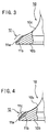
- Figs. 3 and 4 illustrate the valve face in each step for forming a thermal hardened layer and an alloy layer on the inlet valve 10 as shown in Fig. 1.
- valve face 12 On the surface of the valve face 12, powdery materials of reinforcement elements such as Ti, Cr, Ni, Cu, Mn, Fe and Co are applied and heated by high energy heating means such as YAG laser, CO 2 laser and electronic beam.
- high energy heating means such as YAG laser, CO 2 laser and electronic beam.
- a YAG laser is preferable as high energy heating means, but CO 2 laser has low efficiency because of high reflection rats of the Al matrix.
- the surface of the valve face 10 is corroded by acidic or alkaline substance to form uneven surface, thereby accerating absorption of heat energy.
- T6 treatment under JIS (Japanese Industrial Standards) is applied to the valve face 10, thereby recovering hardness of the inner layer 11b.
- JIS Japanese Industrial Standards
- T6 treatment means heating which comprises the steps of rapid cooling by water quenching after heating at about 500°C, and then heating for several hours at 100 to 200°C.
- valve face 10 is heated again by the high energy heating means such as YAG laser to melt the surface layer again and to form the thermal hardened layer on the outermost surface layer 11c of the valve face 10.
- the high energy heating means such as YAG laser
- hardness of the outermost surface layer 11c of the valve face 10 is increased to 250 to 300Hv.
- mechanical strength of the valve face 10 is much increased together with the alloy layer 11a, thereby increasing durability and reliability of the inlet valve 10.
Abstract
Description
- The present invention relates to an Al or Al alloy poppet valve in an internal combustion engine, and a method of manufacturing the same.
- Inlet and exhaust poppet valves in an internal combustion engine for a vehicle is generally made of heat-resistant steel such as martensite and austenite. Recently an inlet valve which has relatively low thermal load is made of Al alloy.
- The heat resistant steel valve has high mechanical strength, and provides high durability and reliability, but has high inertia mass and low heat conductivity.
- The Al alloy inlet valve which is light decreases inertia mass of a valve-operating mechanism, and increase engine performance, thereby providing high heat conductivity and high heat release performance to the cylinder head to increase cooling performance of the engine.
- However, Al alloy has low mechanical strength and especially low wear resistance on the valve face to provide low durability and reliability.
- In view of the foregoing disadvantages, it is an object of the present invention to provide an Al alloy poppet valve in an internal combustion engine which provides increase in strength, especially in mechanical strength of a valve face, and a method of manufacturing it.
- According to one aspect of the present invention, there is provided an Al or Al alloy poppet valve in an internal combustion engine, said valve comprising a valve stem and a valve head at an end of the valve stem, said valve head having a valve face which is engageable on a valve seat, said valve face having a thermal hardened layer at a surface, and an inner alloy layer which contains reinforcement material.
- Thus, the poppet valve increases durability to impact and mechanical strength.
- According to another aspect of the present invention, there is provided a method of manufacturing an Al or Al alloy poppet valve in an internal combustion engine, said method comprising the steps of:
- supplying a reinforcement material onto a valve face of a valve head of the poppet valve;
- melting said reinforcement material by high energy heating means to make said valve face to an alloy;
- applying T6 treatment to said alloy-changed valve face; and
- melting an outermost layer of the valve face subjected to T6 treatment again by said high energy heating means to form a thermal hardened layer.
-
- Hardeness and strength of the valve face of the Al or Al alloy poppet valve are increased, thereby decreasing inertia mass of a valve operating mechanism to increase engine performance.
- The features and advantages of the invention will become more apparent from the following description with respect to embodiments as shown in appended drawings wherein:
- Fig. 1 is a partially sectional side view in which a valve face of a valve head of a poppet valve according to the present invention is partially cut away;
- Fig. 2 is a vertical sectioned front view of a valve operating mechanism which contains the poppet valve according to the present invention;
- Fig. 3 is an enlarged sectional view of the valve face of the poppet valve, showing one step of a method according to the present invention; and
- Fig. 4 is an enlarged sectional view of the valve face, showing another step of the method according to the present invention.
-
- Fig. 1 illustrates a section of a valve face of a valve head of an
inlet valve 10 in an internal combustion engine. Theinlet valve 10 is made of Al alloy such as Al-Si and Al-Si-Cu. Thevalve head 10b is provided at the lower end of avalve stem 10a. - In the
valve face 12 tapered from the lower end of avalve stem 10a to a rearvalve head portion 10c, the surface layer 12a is formed as thermal hardened layer, and an inner layer 12b is made of a reinforcement material such as Ti, Cr, Ni, Cu, Mn, Fe and Co, or an alloy layer of two or more reinforcement elements thereof. The alloy layer has hardness of 250 to 300Hv which is much higher than hardness of Al matrix of 120 to 150Hv. - The alloy layer formed at the lower portion includes intermetallic compounds of Al matrix and reinforcement material, thereby increasing mechanical strength of the inner layer 12b.
- Operation of the inlet valve will be described as below. Fig. 2 illustrates the
inlet valve 10 mounted to acylinder head 14. As shown in Fig. 2, thevalve stem 10a of theinlet valve 10 is slidably inserted in avalve guide 16 of thecylinder head 14. Thevalve face 12 of theinlet valve 10 is engaged on aseat portion 20a of avalve seat 20 at the lower end of aninlet port 18 when an inlet port is closed by the inlet valve, Large impacting force is applied onto thevalve face 12 by engagement with thevalve seat 20. However, the surface layer 12a comprises a hardened layer, and the inner layer 12b comprises an alloy layer, thereby increasing durability to impact significantly. - At the upper end of the
valve stem 10a of theinlet valve 10, aspring retainer 22 is mounted via a pair of cotters (not shown). Between thespring retainer 22 and the upper surface of thecylinder head 14, avalve spring 24 is provided to bias theinlet valve 10 upwards. - Above the
inlet valve 10, arocker arm 26 which moves up and down by a cam (not shown) is provided, and the upper end of theinlet valve 10 is pressed by the lower end of anadjuter bolt 28 which is engaged at the end of therocker arm 26, thereby opening the valve. - A method of manufacturing a valve in an internal combustion engine will be described as below.
- Figs. 3 and 4 illustrate the valve face in each step for forming a thermal hardened layer and an alloy layer on the
inlet valve 10 as shown in Fig. 1. - On the surface of the
valve face 12, powdery materials of reinforcement elements such as Ti, Cr, Ni, Cu, Mn, Fe and Co are applied and heated by high energy heating means such as YAG laser, CO2 laser and electronic beam. Thus, as shown in Fig. 3, analloy layer 11a which contains an alloy and intermetallic compounds are formed on thevalve face 10, thereby obtaining hardness of 250 to 300Hv. - A YAG laser is preferable as high energy heating means, but CO2 laser has low efficiency because of high reflection rats of the Al matrix. The surface of the
valve face 10 is corroded by acidic or alkaline substance to form uneven surface, thereby accerating absorption of heat energy. - In the
inner layer 11b in Fig. 3, there is formed heat-affecting annealed portion which has low hardness, thereby providing buckling during movement of thevalve 10. Thus, T6 treatment under JIS (Japanese Industrial Standards) is applied to thevalve face 10, thereby recovering hardness of theinner layer 11b. By T6 treatment, hardness of the alloy layer is decreased to about 200Hv once. In the meantime, hardness of Al matrix is increased to 120Hv to 150Hv by T6 treatment. T6 treatment means heating which comprises the steps of rapid cooling by water quenching after heating at about 500°C, and then heating for several hours at 100 to 200°C. - Then, the
valve face 10 is heated again by the high energy heating means such as YAG laser to melt the surface layer again and to form the thermal hardened layer on theoutermost surface layer 11c of thevalve face 10. Thus, hardness of theoutermost surface layer 11c of thevalve face 10 is increased to 250 to 300Hv. Accordingly, mechanical strength of thevalve face 10 is much increased together with thealloy layer 11a, thereby increasing durability and reliability of theinlet valve 10. - The foregoing merely relate to embodiments of the invention. Various modifications and changes may be made by persons skilled in the art without departing from the scope of claims.
Claims (5)
- An Al or Al alloy poppet valve in an internal combustion engine, said valve comprising a valve stem and a valve head at an end of the valve stem, said valve head having a valve face which is engageable on a valve seat, said valve face having a thermal hardened layer at a surface, and an inner alloy layer which contains reinforcement material.
- The poppet valve as defined in claim 1 wherein said reinforcement material is Ti, Cr, Ni, Cu, Mn, Fe, Co or an alloy made of two or more elements thereof.
- A method of manufacturing an Al or Al alloy poppet valve in an internal combustion engine, said method comprising the steps of:supplying a reinforcement material onto a valve face of a valve head of the poppet valve;melting said reinforcement material by high energy heating means to make said valve face to an alloy;applying T6 treatment to said alloy-changed valve face; andmelting an outermost layer of the valve face subjected to T6 treatment again by said high energy heating means to form a thermal hardened layer.
- The method as defined in claim 3 wherein said reinforcement material is Ti, Cr, Ni, Cu, Mn, Fe, Co or an alloy made of two or more elements thereof.
- The method as defined in claim 3 wherein said high density energy heating means comprises YAG laser, CO2 laser or electronic beam.
Applications Claiming Priority (3)
| Application Number | Priority Date | Filing Date | Title |
|---|---|---|---|
| JP213110/97 | 1997-08-07 | ||
| JP21311097 | 1997-08-07 | ||
| JP9213110A JPH1162525A (en) | 1997-08-07 | 1997-08-07 | Valve for internal combustion engine and manufacture thereof |
Publications (3)
| Publication Number | Publication Date |
|---|---|
| EP0896130A2 true EP0896130A2 (en) | 1999-02-10 |
| EP0896130A3 EP0896130A3 (en) | 2000-04-12 |
| EP0896130B1 EP0896130B1 (en) | 2002-12-18 |
Family
ID=16633754
Family Applications (1)
| Application Number | Title | Priority Date | Filing Date |
|---|---|---|---|
| EP98114647A Expired - Lifetime EP0896130B1 (en) | 1997-08-07 | 1998-08-04 | Al or Al alloy poppet valve and a method of manufacturing the same |
Country Status (4)
| Country | Link |
|---|---|
| US (1) | US6073912A (en) |
| EP (1) | EP0896130B1 (en) |
| JP (1) | JPH1162525A (en) |
| DE (1) | DE69810211T2 (en) |
Families Citing this family (9)
| Publication number | Priority date | Publication date | Assignee | Title |
|---|---|---|---|---|
| JP2001234313A (en) * | 2000-02-23 | 2001-08-31 | Fuji Oozx Inc | Method for manufacturing engine valve mede of titanium alloy |
| WO2007057946A1 (en) * | 2005-11-15 | 2007-05-24 | Nittan Valve Co., Ltd. | Coolant-containing hollow poppet valve and process for producing the same |
| DE102013216188A1 (en) * | 2013-08-14 | 2015-03-12 | Mahle International Gmbh | Light alloy inlet valve |
| JP5929889B2 (en) | 2013-12-26 | 2016-06-08 | トヨタ自動車株式会社 | Turbocharger |
| DE102015213706A1 (en) * | 2015-07-21 | 2017-01-26 | Mahle International Gmbh | Tribological system comprising a valve seat ring and a valve |
| JP6597663B2 (en) | 2017-02-08 | 2019-10-30 | トヨタ自動車株式会社 | Engine valve |
| CN110914520B (en) | 2018-03-20 | 2021-11-16 | 日锻汽门株式会社 | Hollow lift valve for exhaust |
| JP7190506B2 (en) | 2018-11-12 | 2022-12-15 | 株式会社Nittan | Manufacturing method of engine poppet valve |
| JP7329201B2 (en) | 2020-03-30 | 2023-08-18 | 株式会社Nittan | Manufacturing method of engine poppet valve |
Citations (5)
| Publication number | Priority date | Publication date | Assignee | Title |
|---|---|---|---|---|
| US4117302A (en) * | 1974-03-04 | 1978-09-26 | Caterpillar Tractor Co. | Method for fusibly bonding a coating material to a metal article |
| DE2856232A1 (en) * | 1978-12-27 | 1980-07-17 | Teves Thompson Gmbh | Mushroom valve for exhaust gas turbocharger - has hard metal seat on base covered with corrosion and temp.-resistant layer |
| JPS59128908A (en) * | 1983-01-14 | 1984-07-25 | Mitsubishi Heavy Ind Ltd | Manufacture of poppet valve |
| US4554898A (en) * | 1980-10-31 | 1985-11-26 | Nippon Kokan Kabushiki Kaisha | Exhaust valve for diesel engine and production thereof |
| US5076866A (en) * | 1989-02-17 | 1991-12-31 | Honda Giken Kogyo Kabushiki Kaisha | Heat resistant slide member for internal combustion engine |
Family Cites Families (2)
| Publication number | Priority date | Publication date | Assignee | Title |
|---|---|---|---|---|
| JPS5222623A (en) * | 1975-08-15 | 1977-02-21 | Toyota Motor Corp | Popet valve body and its manufacturing process |
| US4852531A (en) * | 1988-03-10 | 1989-08-01 | Dynamet Technology Inc. | Titanium poppet valve |
-
1997
- 1997-08-07 JP JP9213110A patent/JPH1162525A/en active Pending
-
1998
- 1998-08-04 DE DE69810211T patent/DE69810211T2/en not_active Expired - Fee Related
- 1998-08-04 EP EP98114647A patent/EP0896130B1/en not_active Expired - Lifetime
- 1998-08-07 US US09/131,264 patent/US6073912A/en not_active Expired - Fee Related
Patent Citations (5)
| Publication number | Priority date | Publication date | Assignee | Title |
|---|---|---|---|---|
| US4117302A (en) * | 1974-03-04 | 1978-09-26 | Caterpillar Tractor Co. | Method for fusibly bonding a coating material to a metal article |
| DE2856232A1 (en) * | 1978-12-27 | 1980-07-17 | Teves Thompson Gmbh | Mushroom valve for exhaust gas turbocharger - has hard metal seat on base covered with corrosion and temp.-resistant layer |
| US4554898A (en) * | 1980-10-31 | 1985-11-26 | Nippon Kokan Kabushiki Kaisha | Exhaust valve for diesel engine and production thereof |
| JPS59128908A (en) * | 1983-01-14 | 1984-07-25 | Mitsubishi Heavy Ind Ltd | Manufacture of poppet valve |
| US5076866A (en) * | 1989-02-17 | 1991-12-31 | Honda Giken Kogyo Kabushiki Kaisha | Heat resistant slide member for internal combustion engine |
Non-Patent Citations (1)
| Title |
|---|
| PATENT ABSTRACTS OF JAPAN vol. 008, no. 253 (M-339), 20 November 1984 (1984-11-20) & JP 59 128908 A (MITSUBISHI JUKOGYO KK), 25 July 1984 (1984-07-25) * |
Also Published As
| Publication number | Publication date |
|---|---|
| JPH1162525A (en) | 1999-03-05 |
| DE69810211D1 (en) | 2003-01-30 |
| EP0896130B1 (en) | 2002-12-18 |
| US6073912A (en) | 2000-06-13 |
| EP0896130A3 (en) | 2000-04-12 |
| DE69810211T2 (en) | 2003-06-26 |
Similar Documents
| Publication | Publication Date | Title |
|---|---|---|
| JP3422494B2 (en) | Exhaust valve for internal organs | |
| EP0896130B1 (en) | Al or Al alloy poppet valve and a method of manufacturing the same | |
| JP3380081B2 (en) | Valve seat | |
| EP0743428B1 (en) | Valve seat insert | |
| US5954038A (en) | Combustion face insert | |
| JP3546261B2 (en) | Dissimilar metal materials joining method | |
| US6385847B1 (en) | Seat faced engine valves and method of making seat faced engine valves | |
| JP3421055B2 (en) | Exhaust valve for internal combustion engine | |
| EP0864730A1 (en) | Inlet valve in an internal combustion engine and a method of manufacturing the same | |
| CN1109179C (en) | Mushroom like valve member made of aluminium or aluminium alloy, and making method thereof | |
| KR20000021310A (en) | Aluminum or aluminum alloy poppet valve and preparation thereof | |
| US5743222A (en) | Valve lifter | |
| EP0864731B1 (en) | A1 alloy valve spring retainer | |
| JPH0821216A (en) | Engine valve | |
| EP0730085B1 (en) | A cylinder head and a method for producing a valve seat | |
| JPH10121921A (en) | Valve seat for internal combustion engine | |
| JP3691494B2 (en) | Exhaust valve for internal combustion engine, manufacturing method and regeneration method thereof | |
| EP0711904B1 (en) | Sliding part and a method of producing thereof | |
| JP3660665B2 (en) | Exhaust valve for internal combustion engine, manufacturing method and regeneration method thereof | |
| EP0985806A2 (en) | Valve spring retainer and method of machining the retainer | |
| JPH1061419A (en) | Joint type valve seat and manufacture thereof | |
| JPH0642320A (en) | Valve seat for internal combustion engine | |
| JPH09329008A (en) | Valve spring retainer for internal combustion engine and working method therefor | |
| Deng et al. | Failure analysis on surfacing exhaust valve of 6 Cr 21 Mn 10 MoVNbN steel | |
| JPH1113434A (en) | Method for improving heat radiating performance of fitted body in internal combustion engine cylinder head and fitting part of fitted body |
Legal Events
| Date | Code | Title | Description |
|---|---|---|---|
| PUAI | Public reference made under article 153(3) epc to a published international application that has entered the european phase |
Free format text: ORIGINAL CODE: 0009012 |
|
| AK | Designated contracting states |
Kind code of ref document: A2 Designated state(s): DE FR |
|
| AX | Request for extension of the european patent |
Free format text: AL;LT;LV;MK;RO;SI |
|
| PUAL | Search report despatched |
Free format text: ORIGINAL CODE: 0009013 |
|
| AK | Designated contracting states |
Kind code of ref document: A3 Designated state(s): AT BE CH CY DE DK ES FI FR GB GR IE IT LI LU MC NL PT SE |
|
| AX | Request for extension of the european patent |
Free format text: AL;LT;LV;MK;RO;SI |
|
| 17P | Request for examination filed |
Effective date: 20000320 |
|
| AKX | Designation fees paid |
Free format text: DE FR |
|
| RBV | Designated contracting states (corrected) |
Designated state(s): DE GB |
|
| GRAG | Despatch of communication of intention to grant |
Free format text: ORIGINAL CODE: EPIDOS AGRA |
|
| 17Q | First examination report despatched |
Effective date: 20020423 |
|
| GRAG | Despatch of communication of intention to grant |
Free format text: ORIGINAL CODE: EPIDOS AGRA |
|
| GRAH | Despatch of communication of intention to grant a patent |
Free format text: ORIGINAL CODE: EPIDOS IGRA |
|
| GRAH | Despatch of communication of intention to grant a patent |
Free format text: ORIGINAL CODE: EPIDOS IGRA |
|
| GRAA | (expected) grant |
Free format text: ORIGINAL CODE: 0009210 |
|
| AK | Designated contracting states |
Kind code of ref document: B1 Designated state(s): DE GB |
|
| REG | Reference to a national code |
Ref country code: GB Ref legal event code: FG4D |
|
| REF | Corresponds to: |
Ref document number: 69810211 Country of ref document: DE Date of ref document: 20030130 Kind code of ref document: P Ref document number: 69810211 Country of ref document: DE Date of ref document: 20030130 |
|
| PLBE | No opposition filed within time limit |
Free format text: ORIGINAL CODE: 0009261 |
|
| STAA | Information on the status of an ep patent application or granted ep patent |
Free format text: STATUS: NO OPPOSITION FILED WITHIN TIME LIMIT |
|
| 26N | No opposition filed |
Effective date: 20030919 |
|
| PGFP | Annual fee paid to national office [announced via postgrant information from national office to epo] |
Ref country code: DE Payment date: 20061030 Year of fee payment: 9 |
|
| PGFP | Annual fee paid to national office [announced via postgrant information from national office to epo] |
Ref country code: GB Payment date: 20070627 Year of fee payment: 10 |
|
| PG25 | Lapsed in a contracting state [announced via postgrant information from national office to epo] |
Ref country code: DE Free format text: LAPSE BECAUSE OF NON-PAYMENT OF DUE FEES Effective date: 20080301 |
|
| GBPC | Gb: european patent ceased through non-payment of renewal fee |
Effective date: 20080804 |
|
| PG25 | Lapsed in a contracting state [announced via postgrant information from national office to epo] |
Ref country code: GB Free format text: LAPSE BECAUSE OF NON-PAYMENT OF DUE FEES Effective date: 20080804 |