EP0897707A2 - Compression system - Google Patents
Compression system Download PDFInfo
- Publication number
- EP0897707A2 EP0897707A2 EP98306079A EP98306079A EP0897707A2 EP 0897707 A2 EP0897707 A2 EP 0897707A2 EP 98306079 A EP98306079 A EP 98306079A EP 98306079 A EP98306079 A EP 98306079A EP 0897707 A2 EP0897707 A2 EP 0897707A2
- Authority
- EP
- European Patent Office
- Prior art keywords
- garment
- foot
- bladder
- dorsi
- pressure
- Prior art date
- Legal status (The legal status is an assumption and is not a legal conclusion. Google has not performed a legal analysis and makes no representation as to the accuracy of the status listed.)
- Granted
Links
Images


Classifications
-
- A—HUMAN NECESSITIES
- A61—MEDICAL OR VETERINARY SCIENCE; HYGIENE
- A61H—PHYSICAL THERAPY APPARATUS, e.g. DEVICES FOR LOCATING OR STIMULATING REFLEX POINTS IN THE BODY; ARTIFICIAL RESPIRATION; MASSAGE; BATHING DEVICES FOR SPECIAL THERAPEUTIC OR HYGIENIC PURPOSES OR SPECIFIC PARTS OF THE BODY
- A61H9/00—Pneumatic or hydraulic massage
- A61H9/005—Pneumatic massage
- A61H9/0078—Pneumatic massage with intermittent or alternately inflated bladders or cuffs
-
- A—HUMAN NECESSITIES
- A61—MEDICAL OR VETERINARY SCIENCE; HYGIENE
- A61H—PHYSICAL THERAPY APPARATUS, e.g. DEVICES FOR LOCATING OR STIMULATING REFLEX POINTS IN THE BODY; ARTIFICIAL RESPIRATION; MASSAGE; BATHING DEVICES FOR SPECIAL THERAPEUTIC OR HYGIENIC PURPOSES OR SPECIFIC PARTS OF THE BODY
- A61H2205/00—Devices for specific parts of the body
- A61H2205/12—Feet
Definitions
- This invention relates to a compression system to improve the circulation in a limb extremity, and more particularly, to a foot compression system.
- the compressive pressures may be cyclic and may vary from providing a massaging action to a sharp pulse action.
- the foot is an effective site to apply compressive pressure. It has been shown that the arch of the foot houses a large venous plexus which normally is compressed by means of the foot extending and flattening the arch during walking or running thereby promoting circulation. US Re. 39420 shows a compression device which is said to use this phenomenon by providing a bladder only under the arch of the foot between the balls of the foot and the heel, which upon rapid inflation causes the arch to flatten to simulate the walking or running action. Other devices also exist which simply compress the arch of the foot by applying sharp pulsed, high pressures under the arch by means of an inflatable bag engaging the arch under the mid-foot in conjunction with or without similar devices on the calf and/or the thigh.
- the known devices suffer from the disadvantages that the use of an inflatable bag located only under the arch results in uncomfortable squeezing of the foot due to the constricting shape the foot has to adopt during inflation causing pain to the patient so that the patient's compliance over prolonged use is poor.
- very high pressures are needed to be applied rapidly directly onto the curve of the arch under the midtarsal region of the foot. This region of the arch is without any cushioning and the application of such pumping forces is painful and uncomfortable to the patient further adding to patient compliance difficulties.
- a garment for applying cyclic compressive pressures to a foot comprising at least one bladder adapted to engage substantially the whole of the sole of the foot and also to engage longitudinally the dorsi-medial and dorsi-lateral areas of the top of the foot respectively, means adapted to locate and secure the garment to a foot, means to slowly inflate the bladder to provide a gradual compressive pressure to the sole and to the dorsi-medial and dorsi-lateral areas of a foot, followed by relatively rapid deflation of the bladder.
- the garment of the invention provides compressive pressures applied to the muscle mass of a foot substantially to the whole of the sole and dorsum thereof, which application is very comfortable to the user. Due to the arrangement of the bladder(s) to cover the sole of the foot and the dorsum of the foot, the foot during inflation is not constricted sideways or stretched as with prior art devices but lays flat and therefore avoids the pinching associated with the known devices.
- the garment provides a complementary two-fold stimulation to the blood flow in the foot due to the dual application of compressive pressure on the muscle mass of the foot by the bladder under the sole as well as compressive pressure acting directly on the superficial veins underlying the dorsi-medial and lateral regions of the foot, the former enhancing arterial inflow due to hyperaemia and the latter serving to drive the blood from the veins of the foot.
- the foot garment has been shown to have equivalent effect to the known sharp pulsed, high pressure devices in augmented blood velocity at the femoral vein.
- the biochemical effect is more complicated, the fibrinolytic activity is enhanced and other factors such as the effect of circulating plasminogen activator, tissue plasminogen and other parameters are seen to combine to reduce the risk of clot formation.
- the lower pressures and slow inflation allow the use of a simpler pump to operate the foot garment.
- the garment includes only one bladder.
- the bladder or bladders are inflated over a period of 2 seconds or more, to provide a slow rise in pressure, thereby avoiding any possible damage to the blood cells which may occur with the rapid high pressure rises in the prior art devices.
- the inflation is held for a period of time before deflation, in the cycle, to further enhance arterial blood flow. More preferably the inflation is held for a period less or equal to the period of inflation.
- the bladder is made from vapour permeable material, and more preferably of material having greater elasticity than the garment material so that the bladder provides a more effective transmission of pressure during inflation for any given pressure.
- the means for locating and securement of the garment include cushioning, for example, a foam backing.
- the cushioning for example, foam prevents chafing and skin breakdown at the points of contact, which may be caused by the garment, when in use, by the garment pressing and rubbing against the skin surface during inflation and/or deflation of the bladder within, or by the garment being fitted tight around the foot.
- a garment for applying cyclic compressive pressures to a limb comprising two sheets of plastics material joined together at their peripheries and joined internally to define at least a bladder, wherein the join line at the peripheries is located internally of the edge of the material/garment.
- the join line set back internally of the edge of the garment avoids a hard edge to the garment, thereby preventing chafing of the skin at the points of contact, during use.
- the garment includes securing means, for example, Velcro hook and pile material joined at an edge of the garment.
- the garment includes through holes or apertures through the garment and bladder to provide ventilation to the limb, during use.
- a foot garment blank 10 is formed from two superposed sheets of plastics material 21 and 22, the inner material 21 preferably more elastic than the outer material 22.
- the sheets 21, 22 are high frequency welded together at their peripheries and internally in a pattern defining the bladder 14.
- the high frequency weld is located internally of the peripheries of the garment so that a hard edge consisting of the two material layers and weld join is avoided.
- This peripheral weld which is set back internally allows a soft edge to the garment 22 which has been shown to minimise the problems of chafing at the points of contact known to occur with the prior art garments.
- the outer less elastic material 21 is cut close to the peripheral weld line in order to provide only the softer more elastic material 22 edge in contact with the skin during use.
- the high frequency weld can be replaced by other available means of joining the materials, for example, ultrasonic welding, heat sealing or by adhesive bonding.
- An aperture 31 is provided on the outer material for connection to a pressure source.
- a heel section 30 is further attached to opposing sides of the blank 10 for location of a heel of a patient.
- the heel section includes a foam backing (not shown) to cushion the skin against chafing and skin breakdown at the heel sides during use of the garment.
- the garment 10 is fitted to a foot by positioning the heel of the foot of a patient against the heel section 30 and then the garment is wrapped around the foot and held in place by suitable securing means, preferably cushioned as with the heel section.
- the securing means may have, for example, Velcro hook and pile material 20 on their respective edges or other similar securing means.
- the Velcro hook and pile material 20 is simply sewn or welded at its one edge to the garment edge.
- the bladder surface may have through apertures (not shown) for ventilation of the foot during use.
- the bladder 14 within the garment is inflated slowly, typically for 2.5 seconds by a pressure source to apply compressive pressures, typically to a maximum of 130mmHg, over substantially the whole of the sole of the foot as well as the dorsi-medial and dorsi-lateral areas of the foot.
- the bladder in use, is shown in Fig. 3. This gradual compression of the sole and dorsum regions of the foot is believed to stimulate a larger volume of blood than the known pulsed high pressure pumping devices which act locally only under the arch of the foot.
- the gradual pressure application is very comfortable to the user since lower pressures are applied to a better effect.
- the bladder may be held inflated for a period of time, typically 1 second to further enhance arterial flow.
- the bladder 14 is deflated by exhausting to atmosphere which is fairly rapid compared to the slow rate of inflation.
- the bladder is again inflated typically within a range of 30 to 60 seconds, as desired, in order to maximise the hyperaemic effect for increased arterial inflow and thereby venous outflow.
- the inflation/deflation cycle is carried out as long as treatment is required.
- a valve arrangement or similar, for example, solenoids may be used to control the inflation and deflation cycle and due to the requirement for slow pressure rise time and lower pressures a compressor alone is sufficient to provide the requisite pressurised air.
- the foot garment can be recommended for continual use to provide continual prophylaxis since it can be worn whilst sleeping due to its comfortable gradual compression action.
- the foot garment may be worn in conjunction with a calf or thigh garment for simultaneous stimulation of the venous blood flow or sequential stimulation i.e. starting from the foot, then calf, then thigh as appropriate or the foot garment may be used after actuation of a thigh or calf garment to "prime" the foot prior to its action.
Abstract

Description
- This invention relates to a compression system to improve the circulation in a limb extremity, and more particularly, to a foot compression system.
- It is known to increase or stimulate blood flow by using a compression system to apply compressive pressures to a limb extremity, e.g. a hand, thigh, calf or foot. The compressive pressures may be cyclic and may vary from providing a massaging action to a sharp pulse action.
- It is generally believed that the foot is an effective site to apply compressive pressure. It has been shown that the arch of the foot houses a large venous plexus which normally is compressed by means of the foot extending and flattening the arch during walking or running thereby promoting circulation. US Re. 39420 shows a compression device which is said to use this phenomenon by providing a bladder only under the arch of the foot between the balls of the foot and the heel, which upon rapid inflation causes the arch to flatten to simulate the walking or running action. Other devices also exist which simply compress the arch of the foot by applying sharp pulsed, high pressures under the arch by means of an inflatable bag engaging the arch under the mid-foot in conjunction with or without similar devices on the calf and/or the thigh.
- However, the known devices suffer from the disadvantages that the use of an inflatable bag located only under the arch results in uncomfortable squeezing of the foot due to the constricting shape the foot has to adopt during inflation causing pain to the patient so that the patient's compliance over prolonged use is poor. In addition, in order to provide an effective pumping pressure or flattening of the arch, very high pressures are needed to be applied rapidly directly onto the curve of the arch under the midtarsal region of the foot. This region of the arch is without any cushioning and the application of such pumping forces is painful and uncomfortable to the patient further adding to patient compliance difficulties.
- We have discovered an effect on the circulation system that is dependent on compression of muscle, wherein release of the compression results in reactive hyperaemia which increases the arterial inflow thereby increasing venous outflow. We have found that this increase in venous flow is not dependent on venous priming.
- According to the present invention, there is provided a garment for applying cyclic compressive pressures to a foot comprising at least one bladder adapted to engage substantially the whole of the sole of the foot and also to engage longitudinally the dorsi-medial and dorsi-lateral areas of the top of the foot respectively, means adapted to locate and secure the garment to a foot, means to slowly inflate the bladder to provide a gradual compressive pressure to the sole and to the dorsi-medial and dorsi-lateral areas of a foot, followed by relatively rapid deflation of the bladder.
- The garment of the invention provides compressive pressures applied to the muscle mass of a foot substantially to the whole of the sole and dorsum thereof, which application is very comfortable to the user. Due to the arrangement of the bladder(s) to cover the sole of the foot and the dorsum of the foot, the foot during inflation is not constricted sideways or stretched as with prior art devices but lays flat and therefore avoids the pinching associated with the known devices. Moreover, in use, it is believed that the garment provides a complementary two-fold stimulation to the blood flow in the foot due to the dual application of compressive pressure on the muscle mass of the foot by the bladder under the sole as well as compressive pressure acting directly on the superficial veins underlying the dorsi-medial and lateral regions of the foot, the former enhancing arterial inflow due to hyperaemia and the latter serving to drive the blood from the veins of the foot.
- An important benefit is that lower pressures are necessary to stimulate comparable blood flow as achieved with prior art devices. The foot garment has been shown to have equivalent effect to the known sharp pulsed, high pressure devices in augmented blood velocity at the femoral vein. The biochemical effect is more complicated, the fibrinolytic activity is enhanced and other factors such as the effect of circulating plasminogen activator, tissue plasminogen and other parameters are seen to combine to reduce the risk of clot formation.
- Moreover, the lower pressures and slow inflation allow the use of a simpler pump to operate the foot garment.
- Preferably, the garment includes only one bladder. Preferably, the bladder or bladders are inflated over a period of 2 seconds or more, to provide a slow rise in pressure, thereby avoiding any possible damage to the blood cells which may occur with the rapid high pressure rises in the prior art devices. Preferably, the inflation is held for a period of time before deflation, in the cycle, to further enhance arterial blood flow. More preferably the inflation is held for a period less or equal to the period of inflation.
- Preferably, the bladder is made from vapour permeable material, and more preferably of material having greater elasticity than the garment material so that the bladder provides a more effective transmission of pressure during inflation for any given pressure.
- Preferably, the means for locating and securement of the garment include cushioning, for example, a foam backing. The cushioning, for example, foam prevents chafing and skin breakdown at the points of contact, which may be caused by the garment, when in use, by the garment pressing and rubbing against the skin surface during inflation and/or deflation of the bladder within, or by the garment being fitted tight around the foot.
- In another aspect of the invention there is provided a garment for applying cyclic compressive pressures to a limb, the garment comprising two sheets of plastics material joined together at their peripheries and joined internally to define at least a bladder, wherein the join line at the peripheries is located internally of the edge of the material/garment. The join line set back internally of the edge of the garment avoids a hard edge to the garment, thereby preventing chafing of the skin at the points of contact, during use.
- Preferably, the garment includes securing means, for example, Velcro hook and pile material joined at an edge of the garment.
- Preferably, the garment includes through holes or apertures through the garment and bladder to provide ventilation to the limb, during use.
- Embodiments of the invention will now be described, by way of example, with reference to the accompanying drawings, in which:-
- Figs. 1a and 1b show plan views of garments according to the invention;
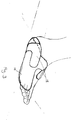
- Fig. 2 is a perspective view of a garment as worn on a foot;
- Fig. 3 is a schematic diagram of the bladder as shown in Fig. 1a as arranged around the foot when the garment is worn as in Fig. 2;
-
- Referring to Fig. 1a, a foot garment blank 10 is formed from two superposed sheets of
plastics material inner material 21 preferably more elastic than theouter material 22. Thesheets bladder 14. The high frequency weld is located internally of the peripheries of the garment so that a hard edge consisting of the two material layers and weld join is avoided. This peripheral weld which is set back internally allows a soft edge to thegarment 22 which has been shown to minimise the problems of chafing at the points of contact known to occur with the prior art garments. The outer lesselastic material 21 is cut close to the peripheral weld line in order to provide only the softer moreelastic material 22 edge in contact with the skin during use. - Conveniently, the high frequency weld can be replaced by other available means of joining the materials, for example, ultrasonic welding, heat sealing or by adhesive bonding.
- An
aperture 31 is provided on the outer material for connection to a pressure source. Aheel section 30 is further attached to opposing sides of the blank 10 for location of a heel of a patient. To further add to the comfort of the user, the heel section includes a foam backing (not shown) to cushion the skin against chafing and skin breakdown at the heel sides during use of the garment. - As shown in Fig. 2, the
garment 10 is fitted to a foot by positioning the heel of the foot of a patient against theheel section 30 and then the garment is wrapped around the foot and held in place by suitable securing means, preferably cushioned as with the heel section. The securing means may have, for example, Velcro hook andpile material 20 on their respective edges or other similar securing means. The Velcro hook andpile material 20 is simply sewn or welded at its one edge to the garment edge. The bladder surface may have through apertures (not shown) for ventilation of the foot during use. - In use, the
bladder 14 within the garment is inflated slowly, typically for 2.5 seconds by a pressure source to apply compressive pressures, typically to a maximum of 130mmHg, over substantially the whole of the sole of the foot as well as the dorsi-medial and dorsi-lateral areas of the foot. The bladder, in use, is shown in Fig. 3. This gradual compression of the sole and dorsum regions of the foot is believed to stimulate a larger volume of blood than the known pulsed high pressure pumping devices which act locally only under the arch of the foot. Moreover, the gradual pressure application is very comfortable to the user since lower pressures are applied to a better effect. Additionally, the bladder may be held inflated for a period of time, typically 1 second to further enhance arterial flow. - The
bladder 14 is deflated by exhausting to atmosphere which is fairly rapid compared to the slow rate of inflation. The bladder is again inflated typically within a range of 30 to 60 seconds, as desired, in order to maximise the hyperaemic effect for increased arterial inflow and thereby venous outflow. The inflation/deflation cycle is carried out as long as treatment is required. - A valve arrangement or similar, for example, solenoids may be used to control the inflation and deflation cycle and due to the requirement for slow pressure rise time and lower pressures a compressor alone is sufficient to provide the requisite pressurised air.
- The foot garment can be recommended for continual use to provide continual prophylaxis since it can be worn whilst sleeping due to its comfortable gradual compression action. The foot garment may be worn in conjunction with a calf or thigh garment for simultaneous stimulation of the venous blood flow or sequential stimulation i.e. starting from the foot, then calf, then thigh as appropriate or the foot garment may be used after actuation of a thigh or calf garment to "prime" the foot prior to its action.
Claims (12)
- A garment for applying cyclic compressive pressures to a foot comprising at least one bladder adapted to engage substantially the whole of the sole of a foot and also to engage longitudinally the dorsi-medial and dorsi-lateral areas of the top of a foot respectively, means adapted to locate and secure the garment to a foot, means to slowly inflate the bladder to provide gradual compressive pressure to the sole and to the dorsi-medial and dorsi-lateral areas of a foot, followed by relatively rapid deflation of the bladder .
- A garment as claimed in claim 1, wherein the garment includes only one bladder.
- A garment as claimed in claim 1 or claim 2, wherein the bladder or bladders are inflated over a period of 2 seconds or more, to provide a slow rise in pressure.
- A garment as claimed in claims 1, 2 or 3, wherein inflation is held for a period of time before deflation, in the cycle.
- A garment as claimed in claim 4, wherein the inflation is held for a period less or equal to the rate of inflation.
- A garment as claimed in any preceding claim, wherein the bladder is made from vapour permeable material.
- A garment as claimed in claim 6, wherein the bladder material is of greater elasticity than the garment material.
- A garment as claimed in any preceding claim, wherein the means for locating and securement of the garment include cushioning, for example, a foam backing.
- A method of applying cyclic compressive pressures to a foot comprising the steps of having at least one bladder engaging substantially the whole of a sole of the foot and the dorsi-medial and dorsi-lateral areas of a top of the foot, applying gradual slow compressive pressure to the areas of the foot engaging the bladder by slowly inflating the bladder, and rapidly releasing the pressure by rapidly deflating the bladder.
- A garment for applying cyclic compressive pressures to a limb, the garment comprising two sheets of plastics material joined together at their peripheries and joined internally to define at least a bladder, wherein the join line at the peripheries is located internally of the edge of the material/garment.
- A garment as claimed in claim 10, wherein the garment includes securing means, for example, Velcro hook and pile material joined at an edge of the garment.
- A garment as claimed in claim 1 or claim 10 or claim 11, wherein the garment includes through holes or apertures through the garment and bladder to provide ventilation to a limb, during use of the garment.
Applications Claiming Priority (3)
| Application Number | Priority Date | Filing Date | Title |
|---|---|---|---|
| GBGB9716851.2A GB9716851D0 (en) | 1997-08-09 | 1997-08-09 | Compression system |
| GB9716851 | 1997-08-09 | ||
| US09/131,038 US6001119A (en) | 1997-08-09 | 1998-08-07 | Compression system |
Publications (3)
| Publication Number | Publication Date |
|---|---|
| EP0897707A2 true EP0897707A2 (en) | 1999-02-24 |
| EP0897707A3 EP0897707A3 (en) | 2003-01-29 |
| EP0897707B1 EP0897707B1 (en) | 2005-11-30 |
Family
ID=26312040
Family Applications (1)
| Application Number | Title | Priority Date | Filing Date |
|---|---|---|---|
| EP98306079A Expired - Lifetime EP0897707B1 (en) | 1997-08-09 | 1998-07-30 | Compression system |
Country Status (6)
| Country | Link |
|---|---|
| US (1) | US6001119A (en) |
| EP (1) | EP0897707B1 (en) |
| DE (1) | DE69832558T2 (en) |
| DK (1) | DK0897707T3 (en) |
| ES (1) | ES2252817T3 (en) |
| GB (2) | GB9716851D0 (en) |
Cited By (4)
| Publication number | Priority date | Publication date | Assignee | Title |
|---|---|---|---|---|
| EP1250115A1 (en) * | 1999-12-27 | 2002-10-23 | Aircast, Inc. | Inflatable medical appliance for prevention of dvt |
| EP2301496A1 (en) * | 2009-09-29 | 2011-03-30 | Tyco Healthcare Group LP | Pneumatic compression garment with noise attenuating means |
| US8469910B2 (en) | 2009-09-29 | 2013-06-25 | Covidien Lp | Pneumatic compression garment with noise attenuating means |
| US9572720B2 (en) | 2009-09-29 | 2017-02-21 | Covidien Lp | Reduced noise pneumatic compression garment |
Families Citing this family (53)
| Publication number | Priority date | Publication date | Assignee | Title |
|---|---|---|---|---|
| US6585669B2 (en) | 1996-06-07 | 2003-07-01 | Medical Dynamics Llc | Medical device for applying cyclic therapeutic action to subject's foot |
| GB2376415A (en) * | 2001-06-12 | 2002-12-18 | Huntleigh Technology Plc | Inflatable pad having restrictively interconnected bladder sections for stimulating blood flow via dorsal & plantar flexion of the foot |
| GB2377178B (en) | 2001-07-06 | 2004-05-19 | Environmental Seals Ltd | Apparatus for relieving the symptoms of deep vein thrombosis |
| US6945944B2 (en) * | 2002-04-01 | 2005-09-20 | Incappe, Llc | Therapeutic limb covering using hydrostatic pressure |
| US7641623B2 (en) | 2003-04-11 | 2010-01-05 | Hill-Rom Services, Inc. | System for compression therapy with patient support |
| US7354410B2 (en) | 2004-02-23 | 2008-04-08 | Tyco Healthcare Group Lp | Compression treatment system |
| US7282038B2 (en) | 2004-02-23 | 2007-10-16 | Tyco Healthcare Group Lp | Compression apparatus |
| US7871387B2 (en) | 2004-02-23 | 2011-01-18 | Tyco Healthcare Group Lp | Compression sleeve convertible in length |
| GB2415149B (en) * | 2004-06-17 | 2006-04-19 | Seymour Burnett John | Foot exerciser |
| US20060020236A1 (en) * | 2004-07-21 | 2006-01-26 | Asher Ben-Nun | Disposable compression sleeve |
| US20060027228A1 (en) * | 2004-07-21 | 2006-02-09 | Moss Edward P | Glass-lined vertical steam smoker evince |
| US8313450B2 (en) * | 2004-07-21 | 2012-11-20 | Mego Afek Ac Ltd. | Inflatable compression sleeve |
| US8172778B2 (en) * | 2004-12-17 | 2012-05-08 | Osim International, Ltd. | Pneumatic massaging device |
| GB0515294D0 (en) | 2005-07-26 | 2005-08-31 | Novamedix Distrib Ltd | Limited durability closure means for an inflatable medical garment |
| US8216165B2 (en) * | 2005-10-27 | 2012-07-10 | Sundaram Ravikumar | Compression garments with heel elevation |
| US7967766B2 (en) * | 2005-10-27 | 2011-06-28 | Sundaram Ravikumar | Compression garment with heel elevation |
| US7442175B2 (en) * | 2005-12-12 | 2008-10-28 | Tyco Healthcare Group Lp | Compression sleeve having air conduit |
| US8029451B2 (en) | 2005-12-12 | 2011-10-04 | Tyco Healthcare Group Lp | Compression sleeve having air conduits |
| US7964829B2 (en) * | 2006-12-20 | 2011-06-21 | Tyco Healthcare Group Lp | Apparatus and method for making bag assembly |
| US8128584B2 (en) | 2007-04-09 | 2012-03-06 | Tyco Healthcare Group Lp | Compression device with S-shaped bladder |
| US8506508B2 (en) | 2007-04-09 | 2013-08-13 | Covidien Lp | Compression device having weld seam moisture transfer |
| US8162861B2 (en) | 2007-04-09 | 2012-04-24 | Tyco Healthcare Group Lp | Compression device with strategic weld construction |
| US8016778B2 (en) | 2007-04-09 | 2011-09-13 | Tyco Healthcare Group Lp | Compression device with improved moisture evaporation |
| USD608006S1 (en) | 2007-04-09 | 2010-01-12 | Tyco Healthcare Group Lp | Compression device |
| US8029450B2 (en) | 2007-04-09 | 2011-10-04 | Tyco Healthcare Group Lp | Breathable compression device |
| US8070699B2 (en) | 2007-04-09 | 2011-12-06 | Tyco Healthcare Group Lp | Method of making compression sleeve with structural support features |
| US8021388B2 (en) | 2007-04-09 | 2011-09-20 | Tyco Healthcare Group Lp | Compression device with improved moisture evaporation |
| US8034007B2 (en) | 2007-04-09 | 2011-10-11 | Tyco Healthcare Group Lp | Compression device with structural support features |
| US8016779B2 (en) | 2007-04-09 | 2011-09-13 | Tyco Healthcare Group Lp | Compression device having cooling capability |
| US8109892B2 (en) | 2007-04-09 | 2012-02-07 | Tyco Healthcare Group Lp | Methods of making compression device with improved evaporation |
| US7959588B1 (en) * | 2007-04-25 | 2011-06-14 | Mark Wolpa | Pressureable compression wrap |
| US8114117B2 (en) | 2008-09-30 | 2012-02-14 | Tyco Healthcare Group Lp | Compression device with wear area |
| US20100042028A1 (en) * | 2008-08-14 | 2010-02-18 | Albahealth, LLC | Foot wrap with inflatable bladder |
| US8235923B2 (en) | 2008-09-30 | 2012-08-07 | Tyco Healthcare Group Lp | Compression device with removable portion |
| US8151851B2 (en) | 2009-06-17 | 2012-04-10 | Tyco Healthcare Group Lp | Apparatus for making bag assembly and method thereof |
| US8502121B2 (en) * | 2009-06-17 | 2013-08-06 | Covidien Lp | Radiofrequency welding apparatus |
| US8652079B2 (en) | 2010-04-02 | 2014-02-18 | Covidien Lp | Compression garment having an extension |
| US9033906B2 (en) | 2010-08-12 | 2015-05-19 | Sun Scientific, Inc. | Therapeutic compression apparatus |
| US10751221B2 (en) | 2010-09-14 | 2020-08-25 | Kpr U.S., Llc | Compression sleeve with improved position retention |
| US8398572B2 (en) | 2010-09-21 | 2013-03-19 | Covidien Lp | Bladder tube connection |
| US8858473B2 (en) * | 2010-10-12 | 2014-10-14 | Venous Health Systems, Inc. | Apparatus, systems, and methods for augmenting the flow of fluid within body vessels |
| US9737454B2 (en) | 2012-03-02 | 2017-08-22 | Hill-Rom Services, Inc. | Sequential compression therapy compliance monitoring systems and methods |
| US9205021B2 (en) | 2012-06-18 | 2015-12-08 | Covidien Lp | Compression system with vent cooling feature |
| US9168197B2 (en) | 2012-09-28 | 2015-10-27 | Covidien Lp | Vascular compression system |
| US9872812B2 (en) | 2012-09-28 | 2018-01-23 | Kpr U.S., Llc | Residual pressure control in a compression device |
| USD737327S1 (en) | 2013-06-17 | 2015-08-25 | Covidien Lp | Display screen with a transitional leak detection icon |
| USD760728S1 (en) | 2013-06-17 | 2016-07-05 | Covidien Lp | Display screen with graphical user interface for patient use meter reset |
| USD737328S1 (en) | 2013-06-17 | 2015-08-25 | Covidien Lp | Display screen with graphical user interface for venous refill detection |
| USD774057S1 (en) | 2013-06-17 | 2016-12-13 | Covidien Lp | Display screen with a graphical user interface for compliance monitoring |
| USD737855S1 (en) | 2013-06-17 | 2015-09-01 | Covidien Lp | Display screen with a transitional venous refill detection icon |
| JP6156700B2 (en) * | 2014-03-13 | 2017-07-05 | パナソニックIpマネジメント株式会社 | Air massage device |
| EP3520760B1 (en) | 2016-02-18 | 2020-11-04 | Hill-Rom Services, Inc. | Patient support apparatus having an integrated limb compression device |
| US11219574B2 (en) * | 2018-07-12 | 2022-01-11 | Barbara Depta | Exercise and therapy devices |
Family Cites Families (16)
| Publication number | Priority date | Publication date | Assignee | Title |
|---|---|---|---|---|
| US132940A (en) * | 1872-11-12 | Improvement in wash-boiler attachments | ||
| US32940A (en) * | 1861-07-30 | |||
| GB1426439A (en) * | 1972-11-13 | 1976-02-25 | Boc International Ltd | Venous flow stimulator |
| US3892229A (en) * | 1973-12-06 | 1975-07-01 | Duane F Taylor | Apparatus for augmenting venous blood flow |
| US3901221A (en) * | 1974-04-08 | 1975-08-26 | Clinical Technology Internatio | Pressure cycle for stimulating blood circulation in the limbs |
| US4453538A (en) * | 1977-04-07 | 1984-06-12 | Whitney John K | Medical apparatus |
| US4696289C1 (en) * | 1983-06-22 | 2002-09-03 | Novamedix Distrib Ltd | Method of stimulating the venous-pump mechanism of the foot and for enhancement of arterial flow to the foot |
| GB2145196B (en) * | 1983-08-18 | 1986-04-09 | Kawaei Co Ltd | Rapid exhaust valve for use in blood circulation stimulator |
| US4827912A (en) * | 1987-09-18 | 1989-05-09 | The Kendall Company | Multi-chamber porting device |
| FR2622777B1 (en) * | 1987-11-06 | 1990-02-09 | Salomon Sa | SKI SHOE SHOE |
| US5135473A (en) * | 1991-01-31 | 1992-08-04 | Marcia Epler | Achilles tendon wrap |
| JP3017569B2 (en) * | 1991-05-30 | 2000-03-13 | 松下電工株式会社 | Air massage control method |
| US5277695A (en) * | 1991-11-08 | 1994-01-11 | Aircast, Inc. | Adjustable ankle compress |
| US5218954A (en) * | 1992-07-09 | 1993-06-15 | Bemmelen Paul S Van | Arterial assist device and method |
| GB2271060B (en) * | 1992-10-01 | 1996-04-03 | Huntleigh Technology Plc | An inflatable garment |
| US5868690A (en) * | 1997-04-30 | 1999-02-09 | Eischen, Sr.; Clement G. | Inflatable boot and method for its manufacture |
-
1997
- 1997-08-09 GB GBGB9716851.2A patent/GB9716851D0/en active Pending
-
1998
- 1998-02-17 GB GB9803280A patent/GB2327888B/en not_active Revoked
- 1998-07-30 ES ES98306079T patent/ES2252817T3/en not_active Expired - Lifetime
- 1998-07-30 DK DK98306079T patent/DK0897707T3/en active
- 1998-07-30 DE DE69832558T patent/DE69832558T2/en not_active Expired - Lifetime
- 1998-07-30 EP EP98306079A patent/EP0897707B1/en not_active Expired - Lifetime
- 1998-08-07 US US09/131,038 patent/US6001119A/en not_active Expired - Lifetime
Non-Patent Citations (1)
| Title |
|---|
| None |
Cited By (8)
| Publication number | Priority date | Publication date | Assignee | Title |
|---|---|---|---|---|
| EP1250115A1 (en) * | 1999-12-27 | 2002-10-23 | Aircast, Inc. | Inflatable medical appliance for prevention of dvt |
| EP1250115A4 (en) * | 1999-12-27 | 2006-06-07 | Aircast Inc | Inflatable medical appliance for prevention of dvt |
| EP2301496A1 (en) * | 2009-09-29 | 2011-03-30 | Tyco Healthcare Group LP | Pneumatic compression garment with noise attenuating means |
| US8328741B2 (en) | 2009-09-29 | 2012-12-11 | Covidien Lp | Pneumatic compression garment with noise attenuating means |
| US8469910B2 (en) | 2009-09-29 | 2013-06-25 | Covidien Lp | Pneumatic compression garment with noise attenuating means |
| US8801644B2 (en) | 2009-09-29 | 2014-08-12 | Covidien Lp | Pneumatic compression garment with noise attenuation |
| US9033905B2 (en) | 2009-09-29 | 2015-05-19 | Covidien Lp | Pneumatic compression garment with noise attenuating means |
| US9572720B2 (en) | 2009-09-29 | 2017-02-21 | Covidien Lp | Reduced noise pneumatic compression garment |
Also Published As
| Publication number | Publication date |
|---|---|
| GB9803280D0 (en) | 1998-04-08 |
| DE69832558D1 (en) | 2006-01-05 |
| GB2327888B (en) | 2001-04-18 |
| US6001119A (en) | 1999-12-14 |
| ES2252817T3 (en) | 2006-05-16 |
| GB9716851D0 (en) | 1997-10-15 |
| DK0897707T3 (en) | 2006-04-03 |
| EP0897707B1 (en) | 2005-11-30 |
| DE69832558T2 (en) | 2006-08-10 |
| EP0897707A3 (en) | 2003-01-29 |
| GB2327888A (en) | 1999-02-10 |
Similar Documents
| Publication | Publication Date | Title |
|---|---|---|
| EP0897707B1 (en) | Compression system | |
| US6592534B1 (en) | Inflatable medical appliance for prevention of DVT | |
| US7282038B2 (en) | Compression apparatus | |
| US4696289A (en) | Method of promoting venous pump action | |
| EP1720505B1 (en) | Compression apparatus | |
| AU2017325804B2 (en) | Therapeutic compression apparatus and methods of use | |
| US7931606B2 (en) | Compression apparatus | |
| USRE32940E (en) | Medical appliance | |
| US4614179A (en) | Medical appliance | |
| US5711760A (en) | Self-inflating venous boot | |
| US6893409B1 (en) | Foot mounted venous compression device | |
| US20120316480A1 (en) | Therapeutic compression apparatus | |
| US20090204037A1 (en) | Compression Apparatus for Applying Intermittent Pressure to the Leg | |
| US20210290478A1 (en) | Thigh therapeutic compression apparatus, system, and methods of use | |
| WO2012142155A2 (en) | Therapeutic compression apparatus | |
| CN204562822U (en) | Inflation sole pressure arteries and veins cover | |
| US20210275386A1 (en) | Therapeutic compression apparatus and methods of use | |
| US20140276286A1 (en) | Non-Woven Garment For Deep Vein Thrombosis Prevention | |
| WO1999037266A1 (en) | Venous boot |
Legal Events
| Date | Code | Title | Description |
|---|---|---|---|
| PUAI | Public reference made under article 153(3) epc to a published international application that has entered the european phase |
Free format text: ORIGINAL CODE: 0009012 |
|
| AK | Designated contracting states |
Kind code of ref document: A2 Designated state(s): AT BE CH CY DE DK ES FI FR GB GR IE IT LI LU MC NL PT SE |
|
| AX | Request for extension of the european patent |
Free format text: AL;LT;LV;MK;RO;SI |
|
| 17P | Request for examination filed |
Effective date: 19990927 |
|
| PUAL | Search report despatched |
Free format text: ORIGINAL CODE: 0009013 |
|
| AK | Designated contracting states |
Designated state(s): AT BE CH CY DE DK ES FI FR GB GR IE IT LI LU MC NL PT SE |
|
| AX | Request for extension of the european patent |
Extension state: AL LT LV MK RO SI |
|
| 17Q | First examination report despatched |
Effective date: 20030507 |
|
| AKX | Designation fees paid |
Designated state(s): BE DE DK ES FR GB IT NL |
|
| GRAP | Despatch of communication of intention to grant a patent |
Free format text: ORIGINAL CODE: EPIDOSNIGR1 |
|
| GRAS | Grant fee paid |
Free format text: ORIGINAL CODE: EPIDOSNIGR3 |
|
| GRAA | (expected) grant |
Free format text: ORIGINAL CODE: 0009210 |
|
| AK | Designated contracting states |
Kind code of ref document: B1 Designated state(s): BE DE DK ES FR GB IT NL |
|
| REG | Reference to a national code |
Ref country code: GB Ref legal event code: FG4D |
|
| REF | Corresponds to: |
Ref document number: 69832558 Country of ref document: DE Date of ref document: 20060105 Kind code of ref document: P |
|
| REG | Reference to a national code |
Ref country code: DK Ref legal event code: T3 |
|
| REG | Reference to a national code |
Ref country code: ES Ref legal event code: FG2A Ref document number: 2252817 Country of ref document: ES Kind code of ref document: T3 |
|
| ET | Fr: translation filed | ||
| PLBE | No opposition filed within time limit |
Free format text: ORIGINAL CODE: 0009261 |
|
| STAA | Information on the status of an ep patent application or granted ep patent |
Free format text: STATUS: NO OPPOSITION FILED WITHIN TIME LIMIT |
|
| 26N | No opposition filed |
Effective date: 20060831 |
|
| NLT1 | Nl: modifications of names registered in virtue of documents presented to the patent office pursuant to art. 16 a, paragraph 1 |
Owner name: HUNTLEIGH TECHNOLOGY LIMITED |
|
| BECN | Be: change of holder's name |
Owner name: HUNTLEIGH TEZCHNOLOGY LTD Effective date: 20051130 |
|
| REG | Reference to a national code |
Ref country code: FR Ref legal event code: CD |
|
| PGFP | Annual fee paid to national office [announced via postgrant information from national office to epo] |
Ref country code: FR Payment date: 20110805 Year of fee payment: 14 Ref country code: DK Payment date: 20110725 Year of fee payment: 14 |
|
| PGFP | Annual fee paid to national office [announced via postgrant information from national office to epo] |
Ref country code: GB Payment date: 20110725 Year of fee payment: 14 Ref country code: DE Payment date: 20110727 Year of fee payment: 14 Ref country code: ES Payment date: 20110726 Year of fee payment: 14 |
|
| PGFP | Annual fee paid to national office [announced via postgrant information from national office to epo] |
Ref country code: BE Payment date: 20110728 Year of fee payment: 14 Ref country code: NL Payment date: 20110728 Year of fee payment: 14 Ref country code: IT Payment date: 20110727 Year of fee payment: 14 |
|
| BERE | Be: lapsed |
Owner name: HUNTLEIGH TEZCHNOLOGY LTD Effective date: 20120731 |
|
| REG | Reference to a national code |
Ref country code: NL Ref legal event code: V1 Effective date: 20130201 |
|
| GBPC | Gb: european patent ceased through non-payment of renewal fee |
Effective date: 20120730 |
|
| REG | Reference to a national code |
Ref country code: DK Ref legal event code: EBP |
|
| REG | Reference to a national code |
Ref country code: FR Ref legal event code: ST Effective date: 20130329 |
|
| PG25 | Lapsed in a contracting state [announced via postgrant information from national office to epo] |
Ref country code: GB Free format text: LAPSE BECAUSE OF NON-PAYMENT OF DUE FEES Effective date: 20120730 Ref country code: FR Free format text: LAPSE BECAUSE OF NON-PAYMENT OF DUE FEES Effective date: 20120731 Ref country code: DE Free format text: LAPSE BECAUSE OF NON-PAYMENT OF DUE FEES Effective date: 20130201 Ref country code: NL Free format text: LAPSE BECAUSE OF NON-PAYMENT OF DUE FEES Effective date: 20130201 |
|
| PG25 | Lapsed in a contracting state [announced via postgrant information from national office to epo] |
Ref country code: BE Free format text: LAPSE BECAUSE OF NON-PAYMENT OF DUE FEES Effective date: 20120731 Ref country code: IT Free format text: LAPSE BECAUSE OF NON-PAYMENT OF DUE FEES Effective date: 20120730 |
|
| PG25 | Lapsed in a contracting state [announced via postgrant information from national office to epo] |
Ref country code: DK Free format text: LAPSE BECAUSE OF NON-PAYMENT OF DUE FEES Effective date: 20120731 |
|
| REG | Reference to a national code |
Ref country code: DE Ref legal event code: R119 Ref document number: 69832558 Country of ref document: DE Effective date: 20130201 |
|
| REG | Reference to a national code |
Ref country code: ES Ref legal event code: FD2A Effective date: 20131018 |
|
| PG25 | Lapsed in a contracting state [announced via postgrant information from national office to epo] |
Ref country code: ES Free format text: LAPSE BECAUSE OF NON-PAYMENT OF DUE FEES Effective date: 20120731 |