EP0899119A1 - Machine-detectable security marking invisible to the human eye, preparation of the security marking and security system using this security marking - Google Patents
Machine-detectable security marking invisible to the human eye, preparation of the security marking and security system using this security marking Download PDFInfo
- Publication number
- EP0899119A1 EP0899119A1 EP98115212A EP98115212A EP0899119A1 EP 0899119 A1 EP0899119 A1 EP 0899119A1 EP 98115212 A EP98115212 A EP 98115212A EP 98115212 A EP98115212 A EP 98115212A EP 0899119 A1 EP0899119 A1 EP 0899119A1
- Authority
- EP
- European Patent Office
- Prior art keywords
- security
- liquid crystalline
- security marking
- color
- marking
- Prior art date
- Legal status (The legal status is an assumption and is not a legal conclusion. Google has not performed a legal analysis and makes no representation as to the accuracy of the status listed.)
- Granted
Links
Images


Classifications
-
- G—PHYSICS
- G06—COMPUTING; CALCULATING OR COUNTING
- G06K—GRAPHICAL DATA READING; PRESENTATION OF DATA; RECORD CARRIERS; HANDLING RECORD CARRIERS
- G06K19/00—Record carriers for use with machines and with at least a part designed to carry digital markings
- G06K19/06—Record carriers for use with machines and with at least a part designed to carry digital markings characterised by the kind of the digital marking, e.g. shape, nature, code
- G06K19/06009—Record carriers for use with machines and with at least a part designed to carry digital markings characterised by the kind of the digital marking, e.g. shape, nature, code with optically detectable marking
- G06K19/06046—Constructional details
-
- B—PERFORMING OPERATIONS; TRANSPORTING
- B41—PRINTING; LINING MACHINES; TYPEWRITERS; STAMPS
- B41M—PRINTING, DUPLICATING, MARKING, OR COPYING PROCESSES; COLOUR PRINTING
- B41M3/00—Printing processes to produce particular kinds of printed work, e.g. patterns
- B41M3/14—Security printing
-
- B—PERFORMING OPERATIONS; TRANSPORTING
- B42—BOOKBINDING; ALBUMS; FILES; SPECIAL PRINTED MATTER
- B42D—BOOKS; BOOK COVERS; LOOSE LEAVES; PRINTED MATTER CHARACTERISED BY IDENTIFICATION OR SECURITY FEATURES; PRINTED MATTER OF SPECIAL FORMAT OR STYLE NOT OTHERWISE PROVIDED FOR; DEVICES FOR USE THEREWITH AND NOT OTHERWISE PROVIDED FOR; MOVABLE-STRIP WRITING OR READING APPARATUS
- B42D25/00—Information-bearing cards or sheet-like structures characterised by identification or security features; Manufacture thereof
- B42D25/20—Information-bearing cards or sheet-like structures characterised by identification or security features; Manufacture thereof characterised by a particular use or purpose
- B42D25/29—Securities; Bank notes
-
- G—PHYSICS
- G03—PHOTOGRAPHY; CINEMATOGRAPHY; ANALOGOUS TECHNIQUES USING WAVES OTHER THAN OPTICAL WAVES; ELECTROGRAPHY; HOLOGRAPHY
- G03G—ELECTROGRAPHY; ELECTROPHOTOGRAPHY; MAGNETOGRAPHY
- G03G21/00—Arrangements not provided for by groups G03G13/00 - G03G19/00, e.g. cleaning, elimination of residual charge
- G03G21/04—Preventing copies being made of an original
- G03G21/043—Preventing copies being made of an original by using an original which is not reproducible or only reproducible with a different appearence, e.g. originals with a photochromic layer or a colour background
-
- G—PHYSICS
- G06—COMPUTING; CALCULATING OR COUNTING
- G06K—GRAPHICAL DATA READING; PRESENTATION OF DATA; RECORD CARRIERS; HANDLING RECORD CARRIERS
- G06K7/00—Methods or arrangements for sensing record carriers, e.g. for reading patterns
- G06K7/10—Methods or arrangements for sensing record carriers, e.g. for reading patterns by electromagnetic radiation, e.g. optical sensing; by corpuscular radiation
- G06K7/12—Methods or arrangements for sensing record carriers, e.g. for reading patterns by electromagnetic radiation, e.g. optical sensing; by corpuscular radiation using a selected wavelength, e.g. to sense red marks and ignore blue marks
Definitions
- the invention relates to a machine-detectable machine that cannot be seen by the eye Security marking, manufacturing the security marker and a security system comprehensive this security marker.
- optically variable elements propagated as a security marker.
- optically variable security markings include diffraction gratings, holograms, interference coatings, metameric colors and polarizing Coatings.
- DE 3942 663 discloses data carriers with an optically variable security element.
- the security element contains a liquid crystal material made of liquid crystal polymer in an oriented form at room temperature, in the form of a solid.
- DE 3942 663 discloses the use of liquid crystal polymer systems with lattice constants 300-1000 nm, which results in a reflection wavelength of 450 to 1500 nm for the liquid crystalline material with an average refractive index of usually 1.5 for liquid crystalline materials.
- the arbitrary combination of LC system with "classic colors", as well as semi-finished products and methods for the production of the security elements as well as methods and machine test arrangements for the detection of color, color flop and polarization of the security elements is disclosed.
- the central wavelength test carried out there is not sufficient for increased security against counterfeiting. This is shown in the comparative example of the present application.
- DE 19544130 describes optically variable security elements known at least two imprints.
- the first imprint is structured with color contrasting with the data carrier, and the second print is without optically variable pigments or executed with only slight body color and superimposed at least partially the first imprint.
- To be discribed also manufacturing processes for such optically variable Security elements.
- the object of the invention is to provide security markings to provide their counterfeit protection against known security markings is increased.
- the task is solved by a security marking containing liquid-crystalline material with chiral phase, thereby characterized in that the security marking with the Eye is not recognizable and the properties of the liquid crystalline Materials with a chiral phase using detection devices can be detected.
- the invention also relates to objects with the invention Safety markings are marked.
- counterfeiters will not be able to see them, or only with difficulty Marking according to the invention at defined positions of the marked object different, machine detectable Characteristics. Through this combination, the security against counterfeiting increased again.
- the invention thus also relates to objects with the invention Security marking so marked are that the security marking according to the invention defined Positions of the marked object different, has machine-detectable properties.
- the security marking according to the invention is compared to the markings known from the prior art only under reproducible much higher effort, which in turn the Counterfeit protection increased.
- chiral phase liquid crystalline material is selected so that the long-wave flank of the reflection band of the Liquid-crystalline material with a chiral phase is preferred is in the range from 200 to 420 nm or the short-wave flank the reflection band of the liquid crystalline material with chiral phase preferably in the range from 700 to 3000 nm lies.
- the long-wave flank of the reflection band is particularly preferably located of the liquid crystalline material with a chiral phase in the range from 250 to 420 nm or the short-wave flank the reflection band of the liquid crystalline material with chiral Phase is in the range of 1501 to 3000 nm.
- the long-wave flank of the reflection band is particularly preferably located of the liquid crystalline material with a chiral phase in the range of 300 to 400 nm or the short-wave flank the reflection band of the liquid crystalline material with chiral Phase in the range from 1501 to 2500 nm.
- Liquid-crystalline materials with a chiral phase use to produce security markings according to the invention are from the prior art, e.g. from the in the fonts mentioned in Examples 1.1 to 1.5.
- the invention also relates to the use of liquid crystalline Materials with a chiral phase, their long-wave Flank of the reflection band in the range from 200 to 420 nm lies, or the short-wave edge of the reflection band in the Range from 700 to 3000 nm, to produce a Security marker.
- the markings according to the invention can be e.g. described in the examples.
- the security marker can u. a. also produced by multi-layer technology become.
- Polarization liquid-crystalline materials with a chiral phase have a left or right handedness of the helical structure.
- the wavelength-selective reflected light is left or right circularly polarized and is accordingly in the following denoted by lh or rh.
- Flank of the reflection band the wavelength at which the intensity the reflection band to 10% of its maximum value has dropped.
- the "short-wave flank of the reflection band” corresponds to the wavelength at which the short-wave branch
- the "long-wave edge of the reflection band” corresponds to the wavelength, where the long-wave branch to 10% of the maximum intensity has dropped.
- Color is not only what is perceptible to the human eye Color impression of the wavelength range of the visible To understand light, but also with human Not perceptible to the eye, but using known devices such as UV and IR spectrometer measurable color impression of the neighboring UV or IR wavelength ranges.
- Color flop spectral color shift of the reflected / transmitted light when the light is not perpendicular.
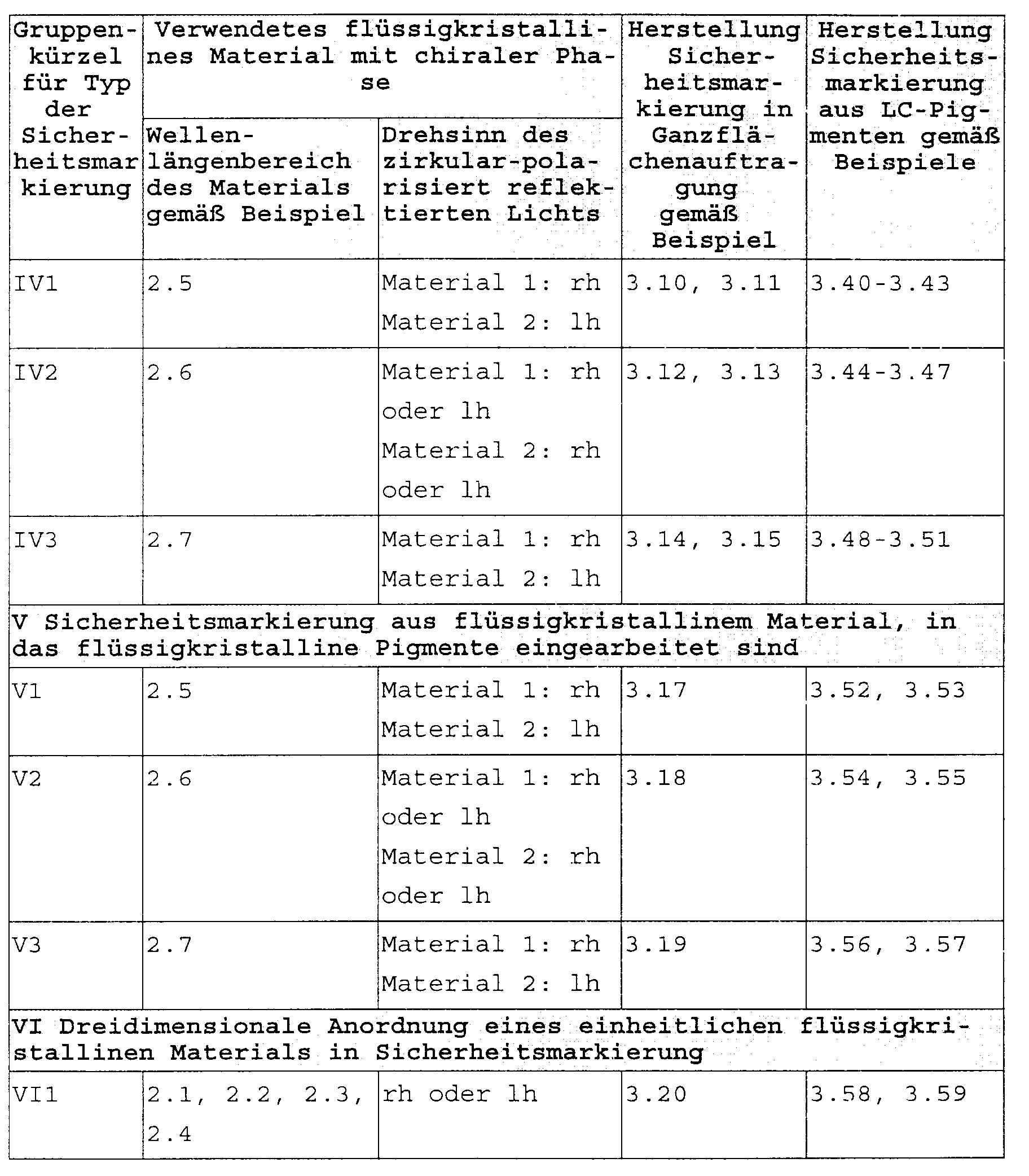
- Table 1 summarizes the selection of the liquid-crystalline materials with a chiral phase described in the examples, and methods for producing security markings according to the invention from these materials under the abovementioned preambles.
- the invention further relates to methods for producing inventive Security markings.
- the inventive method is characterized in that liquid-crystalline materials with chiral phase, their long-wave Flank of the reflection band in the range from 200 to 420 nm, or the short-wave edge of the reflection band in the
- the invention further relates to a security system comprising the security marking according to the invention and a Test arrangement for recognizing the security marking.
- the security system according to the invention is a combination made of invisible, liquid crystalline material with chiral Phase leading to a tamper evident security marking is processed with a test arrangement for preferably complete identification of those for the liquid crystalline Materials characteristic and for security marking properties selected as relevant.
- Properties selected as relevant are preferably Handedness, the color or the color flop of the respective liquid crystalline Material with chiral phase or the defined Arrangement of the material.
- the color is measured by measuring the shape of the reflection band of the liquid-crystalline material with a chiral phase.
- the color flop is measured by measuring at least two under different angular configurations certain center wavelengths the reflection band of the liquid crystalline material determined with a chiral phase.
- the handedness of the material is determined by measuring the polarization of the liquid crystalline material with chiral phase reflected light determined.
- the determination of the defined arrangement of the material will by measuring the aforementioned properties for each liquid crystalline Component of the material made separately.
- the test arrangement according to the invention detects the characteristic Shape of the reflection band in that at least two spectral different points of the reflection band the reflection intensity is determined.
- the test arrangement according to the invention preferably detects the characteristic form of the reflection band in that in Center (center wavelength) of the reflection band is measured and in the wavelength range, where the intensity of the reflection band reached less than 50% of their maximum value.
- the test arrangement according to the invention particularly preferably detects the characteristic shape of the reflection band in that in Center (center wavelength) of the reflection band and in the wavelength range the reflection band is measured where the intensity the reflection band is less than 10% of its maximum Is worth.
- test arrangement is used in the sense of the invention understood an arrangement in which the security marking is illuminated by one or more lighting units and that reflected or transmitted by the security marker Light checked in one or more detection units becomes.
- a lighting unit (B, B1, B2, B3) consists of one Light source and optionally an imaging system (for example Condenser), one or more wavelength selective Elements such as color filters and heat filters as well as, if necessary Light guide.
- an imaging system for example Condenser
- one or more wavelength selective Elements such as color filters and heat filters as well as, if necessary Light guide.
- the choice and number of filters depends on the used test arrangement and the safety marking to be tested and is detailed in the presentation of the test arrangements described.
- Use test arrangement preferably:
- BE1 lighting unit (1) with beam focusing and color selection
- This directional lighting unit consists of a light source (2), a condenser (3) and one or more wavelength selective Elements (4).
- a lighting device is shown by way of example in FIG. 1.
- the light that falls on the security marking (5) is by color filter (4) selected spectrally. This selection is made, for example in that the filter, as shown in Fig. 1, on a rotatable filter wheel (6) can be arranged. Another One possibility is to arrange these filters on a moving one Slider.
- BE2 lighting unit with beam focusing
- This directional lighting unit consists of a light source and a condenser. It corresponds to a lighting source, as shown in Fig. 1, without color-selective Filter.
- the illuminated area should be selected so that the representative properties are correctly characterized when testing the security marking. For example, in the case of mixtures of different pigments, a representative number of individuals should lie within the illumination spot. In the case of structured security elements, all or at least a characteristic part of the element should lie within the illumination spot.
- a planar illumination can be constructed, for example, in such a way that a directional illumination unit is expanded by a single or multi-lens imaging system.
- BE6 diffuse lighting unit (e.g. integrating sphere)
- broadband light sources for the UV range are deuterium lamps, high pressure mercury lamps or Xenon lamps.
- broadband light sources for the IR range are tungsten halogen lamps, high pressure mercury lamps or Xenon lamps.
- Examples of such monochromatic and wave-selected Light sources are laser light or metal halide lamps.
- the selection of the detection units D (D1, D2, D3) is as follows shown:
- a detection unit consists of one or more receivers, which are optionally color and / or polarization selective Elements are upstream. The selection and number of filters depends on the test setup used and the one to be tested Security marking and is in the presentation of the Test arrangements described in detail.
- the receiver should preferably only detect the light intensity and should not react selectively to color or polarization.
- a photomultiplier or a silicon photodiode can be used in the UV and visible spectral range and a PbS (lead sulfide) element for the IR range.
- PbS lead sulfide
- FIG. 2 shows an example of a detection device in which both a color and a polarization selection are carried out. That reflected by the security marker (5) Light is selected using various color filters (4) For example, as shown, a filter wheel (6) in the Beam path are brought. Another option is Arrangement of these filters on a movable slide. The color-selected light then hits the Lambda / 4 delay element (11). That from the security marker outgoing, circularly polarized light is in this Element converted to linearly polarized light. In the following polarization-selective beam splitter prism (12) a selection in the two perpendicular to each other Directions of polarization. The two polarized beams then meet the respective recipient (13) E1 or E2. When selecting the optical elements, these are the expert known criteria of adaptation to the selected Spectral range.
- the delay property over the selected spectral range must be observed.
- Fresnel rhombuses made of calcite in the visible and IR range Wavelength-selected stretched PC foils or Fresnel rhombuses made from calcite.
- the polarizing beam splitter prism for spatial separation of the two linear polarization components can, for example a Glan-Thompson prism with an air gap for the UV range or with IR-transparent cement for the IR range be.
- the selection angle of this prism type is independent of wavelength.
- DE2 Detector (20) with polarization selection and wavelength selection Filter and a receiver
- the detection arrangement DE1 is modified so that only one Receiver (13) is used. This is exemplified in FIG. 3 shown. That of the security marker (5) reflected light is selected using various color filters (4), for example, as shown, via a filter wheel (6) be brought into the beam path. Another possibility is the arrangement of these filters on a movable Slider. The color-selected light then hits right circular (22) and left circular (23) polarizing elements, for example, as shown, with a movable Slider (21) are introduced into the beam path.
- the light reflected by the security marker will selected by different color filters, for example via a filter wheel or a movable slide in the Beam path are brought.
- the light reflected by the security marking is unselected, so neither by a color nor by a polarization test, detected.
- a spatially resolved detection of the incident radiation is achieved by using, for example, a video camera.
- the system consists of a series of color filters and / or polarizers that can be inserted into the beam path, a video camera and the associated electronic evaluation system.
- An imaging system consisting of one or more lenses focuses the light emanating from the security element into the video camera.
- the color filters and / or polarizers can also be introduced in the beam path between the light source and the marking.
- the criteria specified in the test arrangements apply to the selection of the selected components, such as filters and polarizers.
- FIG. 4 shows the basic structure of the test arrangement 1 (30).
- a security marking (5) with liquid crystalline Material is provided by the lighting units B1 and B2 either Irradiated simultaneously or sequentially, that of the security marker color and polarization-selected light is detected with the detector units D1 and D2 and analyzed.
- a check is carried out on the Color of the security marker (5), with a1 as the angle between illuminating light beam from the lighting unit B1 and the normal on the security marking (5) is defined and b1 as the angle that the detector D1 with the normal takes on the security marking.
- the angle between illuminating light beam is the Light source B2 and the normal on the security marking is defined and with b2 the angle that the detector 2 with the normal takes on the security marking.
- Adherence to the gloss condition is not mandatory, but too to prefer.
- the characteristic shape of the reflection band is recorded, by at least three spectrally different points in the Detection in the center and in the flanks of the reflection band he follows.
- the Checking the polarization property of the Security marker Preferably at the center wavelength of the reflection band, that is, at maximum signal intensity, the Checking the polarization property of the Security marker.
- Fig. 5 shows two reflection bands (50), as for the claimed Security markings are typical when under two different angles a1, b1 and a2, b2 illuminated, detected becomes.
- the recognition of these two bands as characteristic Feature of the claimed security markings is carried out by three narrow-band filters per band.
- Interference filters are preferably used as filters, their bandwidth in relation to the reflection band of the to be detected Security elements is chosen so that the Bandwidth of the filter between 0.5 and 5%, preferably at 1% the wavelength of the mean value of the reflection band.
- the center wavelength of the reflection band 1000 nm is the center wavelength of the reflection band 1000 nm, preferably a filter with a bandwidth of 10 nm is used.
- FIG. 6 shows the spectra already known from FIG. 5, wherein the criteria for the selection of filters F1 to F6 as for FP1-1 are valid.
- FP5-1 Color and color flop testing for structured security markings (II1-II3) and three-dimensionally embedded Security marking (VI1)
- a security marking consists of more than one LC species
- the individual LC species in the area can be selected by moving the marking or the test arrangement. If there are two or more different liquid-crystalline species of different colors within the illumination / detection area, a further set of filters is required for each liquid-crystalline species according to the criteria described for FP1-1 or FP3-1.
- the angular position (a1, b1) is preferably at the filter position F2.
- test arrangement PA1 can be constructed as a double or multiple system, the second and the other lighting and detection groups are circular arranged rotated around the normal on the sample surface become.
- B1 B2 D1 D2 comment BE2 BE2 DE1 DE3 Filter selection for DE1 and DE3 according to FP1-1 to FP4-1 BE5 BE5 DE1 DE3 Filter selection for DE1 and DE3 according to FP1-1 to FP4-1 BE3 DE1 DE3 B1 and B2 is realized by a BE3 light source with two light guides BE6 DE1 DE3 B1 and B2 is realized by a diffuse lighting unit BE6
- Fig. 7 shows a variant, such as security markings (5) can be tested with liquid crystalline materials.
- the master has the same reflection properties like the security marker to be checked, is, however, applied to a transparent support.
- the security marker is simultaneously or successively by means of the lighting unit B1 and B2 at the angles a1 and a2 illuminated.
- Such lighting units are, for example the systems described under BE2 or BE5.
- Wavelength- and polarization-selective reflected light meets at angles c1 and c2 within the overall arrangement located master (M1 or M2) and is from there at the angle d1 or d2 completely into the detector D1 or D3 reflected.
- a detector is for example the system described under DE6.
- a wrong polarization component occurs with a counterfeit element and / or light outside the reflection band. This light is transmitted by the master and reaches the detector D2 or D4. Due to the different incidence of the Real security markings can be shone on the detectors and fake security marks safely and distinguish from each other with great sensitivity.
- the security marking (5) is provided by three lighting units (B1, B2, B3) at three angles (a1, a2, a3) illuminated and the reflected light at three angles (b1, b2, b3) detected by the detection units (D1, D2, D3).
- B1, B2, B3 three lighting units
- a1, a2, a3 illuminated
- b1, b2, b3 the detection units
- D1, D2, D3 the detection units
- Adherence to the gloss condition is not mandatory, but too to prefer.
- Structured security markings (corresponding to II1 - II3 in Table 1) can be recognized by imaging their entire outline or parts of the outline on a video camera and comparing them with an electronically stored master. With such an arrangement, even complex patterns in their entirety can be recognized mechanically. Complex structured markings increase the security against counterfeiting.
- the test arrangement PA4 is constructed from two beam paths with the angular configurations (a1, b1) and (a2, b2) as described for the test arrangement PA1, or from three beam paths with the angular configurations (a1, b1), (a2, b2) and (a3 , b3), as described for test arrangement PA3.
- Such a test arrangement (60) is shown in FIG. 11, but only with an angular configuration (a1, b1).
- the lighting system consists of a light source (1) and an imaging system (61), which illuminates the entire structured security element or part of the structured security element at an angle a1 (for example BE5). The light reflected at the angle b1 is analyzed in the detection system.
- the detection system consists of an imaging system (61), consisting of one or more lenses, one or more color filters (62) and / or polarizers (63), a video camera (64) and the associated electronic evaluation system (65).
- the color filters (62) and / or polarizers (63) can also be introduced in the beam path between the light source and the marking (5).
- the partial patterns which are distinguished by different color and / or polarization are digitized and compared with the corresponding electronically stored patterns. The comparison is preferably carried out in such a way that deviations within predetermined tolerances are still accepted.
- the sequential connection of the different color filters and / or polarizers into the beam path detects the partial patterns of different colors and / or polarizations one after the other in the video camera.
- the criteria apply as described for the test arrangements PA1 and PA3.
- the lighting system and detection system are arranged under the angle configuration (a2, b2).
- the color flop is checked by connecting appropriate color filters.
- the criteria apply as described for the test arrangements PA1 and PA3.
- test arrangements according to the invention are not limited to the exemplary detection of reflective Security features.
- Security markings are the same way on transparent surfaces by detection detectable in transmission. The same criteria apply here for lighting and detection as described reflective process.
- Table 2 describes the preferred security systems according to the invention by reproducing the combination of the security markings according to the invention described in Table 1 with the detection systems which are preferably suitable in each case, as described above.
- a filter set with components matched to the LC material must be used in the test arrangement for each LC species of the security marking.
- the invention further relates to the use of the invention Security markings as security element on data carriers, Securities and ID cards.
- the security markings according to the invention can be used with all known security markings, such as, for example are described in DE3942663 combine.
- Example 1.3 Production of liquid crystal material with left handedness of the helical structure
- a desired reflection wavelength (e.g. according to the embodiment 2.1 - 2.4) and the handedness of the helix structure can e.g. B. by mixing liquid crystal material with left handedness of the helix structure from the exemplary embodiment 1.1 or 1.2 or 1.3, or by mixing liquid crystal material with right handedness of the helix structure a right circular polarizing component with a right Handedness from embodiment 1.4 or 1.5, or according to Example 5 from DE 42 34 845 by mixing liquid crystal material with left handedness from embodiment 1.1 or 1.2 or 1.3, with liquid crystal material with right Handedness from example 1.4 or 1.5 set become.
- the reflection wavelength can range from 200 nm (UV) to 3000 nm (IR) can be set specifically.
- the two liquid-crystalline materials are produced in such a way that the characteristic reflection bands of the two materials do not differ or are at least so similar that the center wavelengths of the characteristic reflection bands do not differ by more than 1% of the center wavelength value and the bandwidths of the reflection bands by less than 2%. differ.
- the center wavelengths and handedness of the helix of material 1 and material 2 are set as described in embodiment 1.6 such that the center wavelengths and bandwidths of material 1 and material 2 correspond to the information in one of the embodiments 2.1 to 2.4.
- the two liquid crystalline materials are described as described manufactured in the exemplary embodiments 2.6a or 2.6b, where the center wavelengths of the characteristic Reflection bands of the two materials by more than 1% of the center wavelength value and / or the bandwidths of the reflection bands deviate by more than 2%.
- Embodiment 2.6a material 1: rh, material 2: rh.
- the center wavelengths and handedness of the helix of material 1 and material 2 are set as described in exemplary embodiment 1.6, the center wavelengths and bandwidths of material 1 and material 2 being set as described in one of the exemplary embodiments 2.1 to 2.4.
- Embodiment 2.6b material 1: lh, material 2: lh.
- the center wavelengths and handedness of the helix of material 1 and material 2 are set as described in exemplary embodiment 1.6, the center wavelengths and bandwidths of material 1 and material 2 being set as described in one of the exemplary embodiments 2.1 to 2.4.
- the two liquid crystalline materials are produced in such a way that the characteristic reflection bands of the two materials differ and the handedness of the helix is opposite.
- the two characteristic reflection bands differ when the center wavelengths deviate from one another by more than 1% of the center wavelength value and / or the bandwidths of the reflection bands by more than 2%.
- the center wavelengths and handedness of the helix of material 1 and material 2 are set as described in exemplary embodiment 1.6, the center wavelengths and bandwidths of material 1 and material 2 being set as described in one of the exemplary embodiments 2.1 to 2.4.
- Liquid crystalline material is according to one in EP 358 208 described method on a tear-resistant plastic, for example a polyester film, applied, oriented and networked. All can be described in DE 39 42 663 Variants (e.g. black or colored background, structuring of the subsurface) can be applied.
- Variants e.g. black or colored background, structuring of the subsurface
- Carrier webs with the liquid crystalline materials can for example as described in DE 39 42 663 to narrow Sheets or threads are cut and used as security threads in paper or other substances are embedded. All in Other methods described in DE 39 42 663, for example for the production of transfer elements are also possible (DE 39 42 663 is incorporated by reference).
- Example 3.1 two different, Liquid crystalline produced according to embodiment 2.5 Materials are each a carrier material for themselves, for example a polyester film, coated. With the help of known ones Techniques such as stamping are then developed from the The two films thus obtained produced samples that are used for the production a security element, consisting of two same-colored, liquid crystalline materials of different Handedness of the helix can be used. This happens, for example according to the method described in DE 39 42 663 for the production / processing of security elements in Data carriers.
- liquid crystalline materials are on a Backing material, for example a polyester film, after methods described in EP 358 208 using a chambered doctor blade with two separate chambers directly next to each other at the same time doctored, oriented and networked. You get one Film strips with two different ones lying next to each other Liquid crystal surfaces. Further processing a film strip produced in this way is done analogously the method described in DE 39 42 663.
- liquid crystalline materials are each individually according to that described in EP 358208 Method on a tear-resistant plastic, for example one Polyester film, applied, oriented and cross-linked.
- the so carrier webs obtained are then made according to a known method Laminated process, for example with the help of a hot melt adhesive layer applied to the liquid crystalline layer. This is described for example in DE 39 42 663. With the carrier webs obtained in this way, as in DE 39 42 663 described process (for example Manufacture of security threads).
- Example 3.8 The procedure is as in Example 3.8, the used liquid crystalline materials as described in Embodiment 2.5 are produced.
- Example 3.9 The procedure is as in Example 3.9, the used liquid crystalline materials, as in the embodiment 2.5 described.
- Example 3.8 The procedure is as in Example 3.8, the used liquid crystalline materials, as in the embodiment 2.6 described.
- Example 3.9 The procedure is as in Example 3.9, the used liquid crystalline materials, as in the embodiment 2.6 described.
- Example 3.8 The procedure is as in Example 3.8, the used liquid crystalline materials, as in the embodiment 2.7 described.
- Example 3.9 The procedure is as in Example 3.9, the used liquid crystalline materials, as in the embodiment 2.7 described.
- Liquid crystal materials produced are as follows further processed: the first material (“Material 1") becomes pigments as described in EP 0 601 483, Example 1B processed, then into the second material (“Material 2 ”) incorporated, which finally on a tearproof Plastic, for example a polyester film, applied, is oriented and networked.
- the ratio of the first Materials (in pigment form) in relation to the second must be chosen so that the second material under conditions can be sufficiently oriented according to the state of the art.
- the further processing of the coated carrier web into one Security element occurs analogously to that described in DE 39 42 663 Methods.
- Example 3.16 The procedure is as in Example 3.16, with the used liquid crystalline materials, as in the embodiment 2.5 described.
- Example 3.17 The procedure is as in Example 3.17, with the used liquid crystalline materials, as in the embodiment 2.6 described.
- Example 3.18 The procedure is as in Example 3.18, with the used liquid crystalline materials, as in the embodiment 2.7 described.
- the pronounced color flop behavior of liquid-crystalline systems with a chiral phase in different lighting / detection configurations is exploited by fixing the liquid-crystalline system at different points on a security marking (5) in a matrix at different angles, as shown, for example, in FIG.
- the liquid-crystalline material used which is produced in accordance with exemplary embodiment 2.1, 2.2, 2.3 or 2.4, is first applied, oriented and crosslinked to a film, for example a polyester film.
- a plastic matrix, for example made of PVC is converted into a sawtooth shape, for example, by compression molding.
- the carrier web consisting of polyester film with applied liquid-crystalline material
- the carrier web is then applied to the sawtooth structure, for example by lamination using the hot-melt adhesive technique, and finally just covered with a further plastic matrix.
- plane security markings are obtained, which can be incorporated into a map, for example.
- the detection of a security marking produced in this way is carried out as follows: As shown in FIG. 12, the following signal is obtained at two different locations on the security marking with an illumination / detection system, for example as described in exemplary embodiment 4.1:
- the liquid-crystalline material from the exemplary embodiments 1.1 - 1.5, in which, as described in embodiment 2.5, the reflection wavelengths to those in the exemplary embodiments 2.1 - 2.4 values have been set, is according to the method described in EP 0 601 483, Example 1B processed into pigments.
- the pigments thus obtained are using the known screen printing technology and after incorporation into a suitable binder system on a tear-resistant plastic, for example a polyester film, applied.
- the further processing of these foils takes place, for example, according to those described in DE 39 42 663 Methods, including the manufacturing variants described there of security markings can be applied.
- liquid crystalline material is after the method described in EP 0 601 483 incorporated into a PVC.
- the films obtained in this way are further processed as described in embodiment 3.21.
- liquid crystalline materials are used with foils Liquid crystalline material produced, the processing the carrier foils to structured markings, as in Embodiment 3.2 described takes place.
- the carrier films are in accordance with embodiment 3.22 Use of two different ones, as in the exemplary embodiment 2.5 described, produced, liquid-crystalline materials produced, the processing of the carrier films too structured markings, as in embodiment 3.2 described.
- the carrier films are in accordance with embodiment 3.21 Use of two different ones, as in the exemplary embodiment 2.6 described, produced liquid crystalline materials produced, the processing of the carrier films into structured Markings as described in embodiment 3.2 he follows.
- the carrier films are in accordance with embodiment 3.22 Use of two different ones, as in the exemplary embodiment 2.6 described, produced liquid crystalline materials produced, the processing of the carrier films into structured Markings as described in embodiment 3.2 he follows.
- the carrier films are in accordance with embodiment 3.21 Use of two different ones, as in the exemplary embodiment 2.7 described, produced, liquid-crystalline materials produced, the processing of the carrier films too structured markings, as in embodiment 3.2 described.
- the carrier films are in accordance with embodiment 3.22 Use of two different ones, as in the exemplary embodiment 2.7 described, produced, liquid-crystalline materials produced, the processing of the carrier films too structured markings, as in embodiment 3.2 described.
- color-coordinated liquid-crystalline materials are in each case according to the example in EP 0 601 483 1B, processes described are processed into pigments.
- the pigments thus obtained are then mixed A: B (% by weight) processed as follows:
- Detection arrangement can use the relative intensities of the reflection bands determines the quantitative ratios A: B. become.
- liquid crystalline Materials are pigments according to the example in EP 0 601 483 1B, method described. Using a screen printing process using a screen printing binder the pigments are each individually on a tearproof Plastic, for example a polyester film, applied. The further processing of the two carrier webs thus obtained takes place as described in embodiment 3.8.
- Example 3.35 The procedure is as in Example 3.35, with the difference that instead of the screen printing process, the pigments, as described in embodiment 3.22, each individually be worked into a plastic matrix.
- the pigments are prepared as in EP 0 601 483, Example 1C, with a liquid-crystalline double layer as the basis is used, which is described as in exemplary embodiment 3.9, was applied to a carrier film.
- the used here liquid crystalline materials were used as in described the embodiments 2.5, 2.6 or 2.7, manufactured.
- Example 3.37 The pigments produced in Example 3.37 are analogous to the method described in embodiment 3.21 processed by screen printing.
- the carrier web thus obtained becomes markings, as described in embodiment example 3.21 processed further.
- Example 3.37 The pigments produced in Example 3.37 are according to the method described in embodiment 3.22 incorporated into a plastic matrix and, as described there, processed into markings.
- Example 3.39 the liquid crystalline material used, as in Embodiment 2.5 described, was produced.
- Liquid-crystalline materials are, as in the exemplary embodiment 3.16 described, coated carrier webs produced, which, as in EP 06 01 483, Example 1B, to pigments to be processed further.
- the pigments so produced are in the screen printing process according to embodiment 3.21 processed further.
- Liquid-crystalline materials are, as in the exemplary embodiment 3.16 described, coated carrier webs produced, which, as in EP 0 601 483, Example 1B, to pigments to be processed further.
- the pigments so produced are into a plastic matrix according to embodiment 3.22 processed further.
- Liquid-crystalline materials are, as in the exemplary embodiment 3.16 described, coated carrier webs produced, which, as in EP 0 601 483, Example 1B, to pigments to be processed further.
- the pigments so produced are in the screen printing process according to embodiment 3.21 processed further.
- Liquid-crystalline materials are, as in the exemplary embodiment 3.16 described, coated carrier webs produced, which, as in EP 0 601 483, Example 1B, to pigments to be processed further.
- the pigments so produced are into a plastic matrix according to embodiment 3.22 processed further.
- a security marking SM1-1, as described in Table 1 under group code I1, with a right-handed LC species reflecting in the IR spectral range is to be tested.
- the security marking was produced by applying the whole area in accordance with Example 3.1.
- a test arrangement corresponding to PA1 is used. Tests are carried out for color and color flop according to the procedure described under FP1-1 and for polarization according to the description under PP1-1.
- the arrangement described under BE2 is used both times as lighting device B1 and B2.
- a detection device as described under DE1 is used for detection D1 at angle (b1), and a detection device as described under DE3 is used for detection D2 at angle (b2).
- Table 3 shows the signals on the detection system when testing a security marking according to the invention: Signal at D1 Signal onD2 lighting Detection filter E1 (rh) E2 (lh) D2 at angle a1 at angle b1 F1 1 0 at angle a1 at angle b1 F2 1 0 at angle a1 at angle b1 F3 1 0 at angle a2 at angle b2 F4 1 at angle a2 at angle b2 F5 1 at angle a2 at angle b2 F6 1
- the test arrangement PA1 with the described components a fake security marker fed for testing.
- the fake security marking has the following structure: Marking with a narrow reflection band of the same center wavelength and the same height, with a comparable color flop, not polarizing.
- Table 4 shows the signals on the detection system when checking the counterfeit security marking: Signal at D1 Signal at D2 lighting Detection filter E1 (rh) E2 (lh) D2 at angle a1 at angle b1 F1 0 0 at angle a1 at angle b1 F2 0 0 at angle a1 at angle b1 F3 0 0 at angle a2 at angle b2 F4 1 at angle a2 at angle b2 F5 1 at angle a2 at angle b2 F6 1
- Table 5 shows the signals on the detection system when checking the forged security marking: Signal at D1 Signal at D2 lighting Detection filter E1 (rh) E2 (lh) D2 at angle a1 at angle b1 F1 0 0 at angle a1 at angle b1 F2 0 0 at angle a1 at angle b1 F3 0 0 at angle a2 at angle b2 F4 0 at angle a2 at angle b2 F5 0 at angle a2 at angle b2 F6 0
- liquid-crystalline security elements that are recognized as incorrect may be mentioned by way of example: unpolarized element, wide band, with color flop; unpolarized element, narrow band, without color flop; unpolarized element, narrow band, with color flop; linearly polarized element, wide band, without color flop, linearly polarized element, wide band, with color flop; linearly polarized element, narrow band, without color flop; linear polarized element, narrow band, with color flop; circularly polarized element, narrow band, without color flop.
- a circularly polarized element, with a wide band, with a color flop is recognized as false if there is not an identical form of the reflection band and the same wavelength shift in the case of oblique illumination.
- a security marking SM1-2, as described in Tab. 1 under the group code I1, with a right-handed LC species reflecting in the IR spectral range is tested.
- the security marking was produced by applying the whole area in accordance with Example 3.1.
- a test arrangement corresponding to PA2 is used.
- the arrangement described under BE2 is used both times as lighting device B1 and B2.
- one detection device as described under DE6 is used for the detection of D1, D2, D3 and D4, one detection device as described under DE6 is used.
- the determination of the signal level on the detection system is carried out in such a way that the security marking to be detected is compared with a master.
- Table 6 shows the signals on the detection system when testing the security marking according to the invention: Signal at the detectors Security marker D1 D2 D3 D4 SM
- Table 7 shows the signals at the detectors when checking the fake security markings: Signal at the detectors Fake item D1 D2 D3 D4 GM 1-2 0 0 0 0 GM 2-2 0 0 0 0 GM 3-2 0 0 0 0 0 0 0
- a security marking SM1-3 as described in Table 1 under group code III3, with 2 LC species, reflecting in the IR spectral range, of which LC species 1 with color 1 and right-handed polarizing, and LC species 2 with color 2 and polarizing left-handed, will be tested.
- the security marking was produced from pigments in accordance with Example 3.33.
- a test arrangement corresponding to PA3 is used. Testing is carried out for color and color flop according to the procedure described under FP1-3 and for polarization according to the description under PP1-3. Since there are two different colors, FP1-3 should be used separately for each color. Both colors are measured at the same angles.
- the arrangement described under BE5 is used as the lighting device B1, B2 and B3.
- a detection device as described under DE1 is used for detection D1 at angle (b1) and a detection device as described under DE3 is used for detection D2 at angle (b2).
- Detection devices as described under DE3 are used for detection D1 and D3 at angles (b1) and (b3).
- the security marking is illuminated and detected in such an area that both LC species are detected simultaneously and with comparable areas.
- the measured signals are evaluated as described in example 4.1.
- Table 8 shows the signals on the detection system when testing the security marking according to the invention: Signal at the detectors lighting Detection filter D1 E1 (rh) E2 (lh) D3 at angle a1 at angle b1 F1 for color 1 1 F1 for color 2 1 at angle a2 at angle b2 F2 for color 1 1 0 F2 for color 2 0 1 at angle a3 at angle b3 F3 for color 1 1 F3 for color 2 1
- a fake security marking is fed to the test arrangement PA2 with the described components for testing.
- the fake security marking GM 1-2 differs from the security marking SM 1-3 in that the two colors have the same handedness of polarization, for example right-handed.
- Table 9 shows the signals on the detection system when checking the forged security marking: Signal at the detectors lighting Detection filter D1 E1 (rh) E2 (lh) D3 at angle a1 at angle b1 F1 for color 1 1 F1 for color 2 1 at angle a2 at angle b2 F2 for color 1 1 0 F2 for color 2 1 0 at angle a3 at angle b3 F3 for color 1 1 F3 for color 2 1
- the security marking (5) was produced by screen printing pigments in accordance with Example 3.23.
- the lighting unit described under BE6 is used as the lighting device B1 and B2.
- Detection unit DE7 is used for detection in D1 and D2.
- the filter selection for D1 and D2 is carried out according to criteria FP1-1 from PA1.
- the fake security marking (80) GM 1-4 differs from the security marking SM 1-4 in that it is incorrectly structured compared to SM1-4 (see FIG. 15). Otherwise, however, it is made from the same LC species as SM1-4.
- the fake GM 2-4 security marker differs from the SM 1-4 security marker in that it consists of two species with right and left circular light reflection in the same spectral range as SM1-4, but with spectrally broadened reflection. The structuring corresponds to SM 1-2.
- Table 10 shows the signals on the detection system when checking the real and the fake security markings: Detection in D1 filter F1 F2 F3 polarization rh lh rh lh rh lh SM1-4 1 1 1 1 1 1 1 GM1-4 1 1 0 0 1 1 GM2-4 filter 0 F4 0 1 F5 1 0 F6 0 Detection in D2 filter F4 F5 F6 polarization rh lh rh lh rh lh SM1-4 1 1 1 1 1 1 1 GM1-4 1 1 0 0 1 1 GM2-4 0 0 1 1 0 0 0 0 0 0 0 0 0 0 0 0 0 0 0 0 0 0 0 0 0 0 0 0 0 0 0 0 0 0 0 0 0 0 0 0 0 0 0 0 0 0 0 0 0 0
Abstract
Description
Die Erfindung betrifft eine mit dem Auge nicht erkennbare, maschinendetektierbare Sicherheitsmarkierung, die Herstellung der Sicherheitsmarkierung und ein Sicherheitssystem umfassend diese Sicherheitsmarkierung.The invention relates to a machine-detectable machine that cannot be seen by the eye Security marking, manufacturing the security marker and a security system comprehensive this security marker.
Die zunehmende technische Reife von Farbkopierern führt zu Kopien, die in Farbe, Auflösung und Qualität immer weniger von den Originalen zu unterscheiden sind. Als Schutz vor Fälschung mit Hilfe von Farbkopierern oder Scannern wird für Datenträger mehr und mehr die Verwendung von optisch variablen Elementen als Sicherheitsmarkierung propagiert. Solche Markierungen haben gemeinsam, daß sie je nach Beleuchtungs- und Beobachtungsbedingungen unterschiedliche Farb- oder Helligkeitswiedergaben aufweisen. Zu den gebräuchlichsten optisch variablen Sicherheitsmarkierungen zählen Beugungsgitter, Hologramme, Interferenzbeschichtungen, metamere Farben und polarisierende Beschichtungen.The increasing technical maturity of color copiers leads to copies, which are less and less of color, resolution and quality to distinguish the originals. As protection against counterfeiting with the help of color copiers or scanners for data carriers more and more the use of optically variable elements propagated as a security marker. Have such markings common that they depend on lighting and observation conditions different color or brightness renditions exhibit. The most common optically variable security markings include diffraction gratings, holograms, interference coatings, metameric colors and polarizing Coatings.
Aus DE 195 41 028 sind Effektlacke für zu lackierende Gegenstände mit Flüssigkristall-Pigmenten, die eine Kennzeichnung zur Erkennung und Charakterisierung des Gegenstandes tragen, beschrieben. Die Kennzeichnung erfolgt dabei über die Oberflächenstruktur der Pigmente mit einer Schichtstärke > 0,5 µm nach dem Prinzip des Barcodes oder durch definiertes spektrales Verhalten oder durch Farbmuster. Beschrieben werden ferner Verfahren zur Herstellung des Effektlackes und der markierten Pigmente.DE 195 41 028 describes effect paints for objects to be painted with liquid crystal pigments, which is a label to recognize and characterize the object, described. The marking takes place via the surface structure of the pigments with a layer thickness> 0.5 µm according to the principle of the barcode or by defined spectral Behavior or through color samples. Are also described Process for producing the effect varnish and the marked Pigments.
Aus DE 3942 663 sind Datenträger mit optisch variablem Sicherheitselement
bekannt. Das Sicherheitselement enthält ein Flüssigkristallmaterial
aus Flüssigkristall-Polymer in orientierter
Form bei Raumtemperatur, als Festkörper vorliegend.
DE 3942 663 offenbart die Verwendung von Flüssigkristall-Polymer-Systemen
mit Gitterkonstanten 300 - 1000 nm, woraus sich
bei einem mittleren Brechungsindex von üblicherweise 1,5 für
flüssigkristalline Materialien eine Reflexionswellenlänge von
450 bis zu 1500 nm für das flüssigkristalline Material ergibt.
Ferner wird die beliebige Kombination von LC-System mit "klassischen
Farben", sowie Halbzeuge und Verfahren zur Herstellung
der Sicherheitselemente sowie Verfahren und maschinelle
Prüfanordnungen zur Detektion von Farbe, Farbflop und Polarisation
der Sicherheitselemente offenbart. Die dort vorgenommene
Prüfung der Mittenwellenlänge ist für eine erhöhte Fälschungssicherheit
nicht ausreichend. Dies wird im Vergleichsbeispiel
vorliegender Anmeldung gezeigt.DE 3942 663 discloses data carriers with an optically variable security element. The security element contains a liquid crystal material made of liquid crystal polymer in an oriented form at room temperature, in the form of a solid.
DE 3942 663 discloses the use of liquid crystal polymer systems with lattice constants 300-1000 nm, which results in a reflection wavelength of 450 to 1500 nm for the liquid crystalline material with an average refractive index of usually 1.5 for liquid crystalline materials. Furthermore, the arbitrary combination of LC system with "classic colors", as well as semi-finished products and methods for the production of the security elements as well as methods and machine test arrangements for the detection of color, color flop and polarization of the security elements is disclosed. The central wavelength test carried out there is not sufficient for increased security against counterfeiting. This is shown in the comparative example of the present application.
Aus DE 19544130 sind optisch variable Sicherheitselemente aus wenigstens zwei Aufdrucken bekannt. Der erste Aufdruck ist strukturiert mit zum Datenträger kontrastierender Farbe, und der zweite Aufdruck ist mit optisch variablen Pigmenten ohne oder mit nur geringer Körperfarbe ausgeführt und überlagert zumindest teilweise den ersten Aufdruck. Beschrieben werden ferner Herstellverfahren für derartige optisch variable Sicherheitselemente.DE 19544130 describes optically variable security elements known at least two imprints. The first imprint is structured with color contrasting with the data carrier, and the second print is without optically variable pigments or executed with only slight body color and superimposed at least partially the first imprint. To be discribed also manufacturing processes for such optically variable Security elements.
Aufgabe der Erfindung ist es, Sicherheitsmarkierungen zur Verfügung zu stellen, deren Fälschungssicherheit im Vergleich zu bekannten Sicherheitsmarkierungen erhöht ist.The object of the invention is to provide security markings to provide their counterfeit protection against known security markings is increased.
Die Aufgabe wird gelöst durch eine Sicherheitsmarkierung, enthaltend flüssigkristallines Material mit chiraler Phase, dadurch gekennzeichnet, daß die Sicherheitsmarkierung mit dem Auge nicht erkennbar ist und die Eigenschaften des flüssigkristallinen Materials mit chiraler Phase mit Hilfe von Detektionseinrichtungen erfaßt werden können.The task is solved by a security marking containing liquid-crystalline material with chiral phase, thereby characterized in that the security marking with the Eye is not recognizable and the properties of the liquid crystalline Materials with a chiral phase using detection devices can be detected.
Aufgrund der fehlenden Erkennbarkeit für das menschliche Auge infolge der Transparenz des flüssigkristallinen Materials mit chiraler Phase ist die Existenz und/oder Position der Sicherheitsmarkierung auf dem markierten Gegenstand nicht oder zumindest nur erschwert für Fälscher erkennbar, so daß die komplexen Eigenschaften Polarisation-Farbe-Farbflop, die mit einer Detektionseinrichtung positionsabhängig detektiert werden, zu einer Sicherheitsmarkierung mit ausgeprägter Fälschungssicherheit führen.Due to the lack of recognition for the human eye due to the transparency of the liquid crystalline material chiral phase is the existence and / or position of the security marker not on the marked item or at least only difficult for counterfeiters to recognize, so that the complex Properties polarization-color-flop that with a detection device can be detected as a function of position, to a security marking with pronounced counterfeit security to lead.
Die Erfindung betrifft auch Gegenstände, die mit der erfindungsgemäßen Sicherheitsmarkierung gekennzeichnet sind.The invention also relates to objects with the invention Safety markings are marked.
Vorzugsweise zeigt die für Fälscher nicht oder nur schwer erkennbare erfindungsgemäße Markierung an definierten Positionen des markierten Gegenstands unterschiedliche, maschinendektierbare Eigenschaften. Durch diese Kombination wird die Fälschungssicherheit nochmals erhöht.It is preferred that the counterfeiters will not be able to see them, or only with difficulty Marking according to the invention at defined positions of the marked object different, machine detectable Characteristics. Through this combination, the security against counterfeiting increased again.
Die Erfindung betrifft somit auch Gegenstände, die mit der erfindungsgemäßen Sicherheitsmarkierung derart gekennzeichnet sind, daß die erfindungsgemäße Sicherheitsmarkierung an definierten Positionen des markierten Gegenstands unterschiedliche, maschinendetektierbare Eigenschaften aufweist.The invention thus also relates to objects with the invention Security marking so marked are that the security marking according to the invention defined Positions of the marked object different, has machine-detectable properties.
Die erfindungsgemäße Sicherheitsmarkierung ist im Vergleich zu den aus dem Stand der Technik bekannten Markierungen nur unter wesentlich höherem Aufwand reproduzierbar, was wiederum die Fälschungssicherheit erhöht.The security marking according to the invention is compared to the markings known from the prior art only under reproducible much higher effort, which in turn the Counterfeit protection increased.
Das in der erfindungsgemäßen Sicherheitsmarkierung vorhandene flüssigkristalline Material mit chiraler Phase ist so ausgewählt, daß die langwellige Flanke der Reflexionsbande des flüssigkristallinen Materials mit chiraler Phase vorzugsweise im Bereich von 200 bis 420 nm liegt oder die kurzwellige Flanke der Reflexionsbande des flüssigkristallinen Materials mit chiraler Phase vorzugsweise im Bereich von 700 bis 3000 nm liegt.The one present in the security marking according to the invention chiral phase liquid crystalline material is selected so that the long-wave flank of the reflection band of the Liquid-crystalline material with a chiral phase is preferred is in the range from 200 to 420 nm or the short-wave flank the reflection band of the liquid crystalline material with chiral phase preferably in the range from 700 to 3000 nm lies.
Besonders bevorzugt liegt die langwellige Flanke der Reflexionsbande des flüssigkristallinen Materials mit chiraler Phase im Bereich von 250 bis 420 nm oder die kurzwellige Flanke der Reflexionsbande des flüssigkristallinen Materials mit chiraler Phase im Bereich von 1501 bis 3000 nm liegt. The long-wave flank of the reflection band is particularly preferably located of the liquid crystalline material with a chiral phase in the range from 250 to 420 nm or the short-wave flank the reflection band of the liquid crystalline material with chiral Phase is in the range of 1501 to 3000 nm.
Insbesondere bevorzugt liegt die langwellige Flanke der Reflexionsbande des flüssigkristallinen Materials mit chiraler Phase im Bereich von 300 bis 400 nm oder die kurzwellige Flanke der Reflexionsbande des flüssigkristallinen Materials mit chiraler Phase im Bereich von 1501 bis 2500 nm.The long-wave flank of the reflection band is particularly preferably located of the liquid crystalline material with a chiral phase in the range of 300 to 400 nm or the short-wave flank the reflection band of the liquid crystalline material with chiral Phase in the range from 1501 to 2500 nm.
Bei der erfindungsgemäßen Sicherheitsmarkierung kann es sich
- um eine einheitliche Markierung aus einem flüssigkristallinen Material mit chiraler Phase oder
- um eine strukturierte oder nicht strukturierte Sicherheitsmarkierung aus mindestens zwei verschiedenen flüssigkristallinen Materialien mit chiraler Phase oder
- um eine Sicherheitsmarkierung aus flüssigkristallinen Pigmenten, die in flüssigkristallinem Film eingearbeitet, sind oder
- um eine dreidimensionale Anordnung eines einheitlichen flüssigkristallinen Materials handeln.
- for a uniform marking of a liquid crystalline material with a chiral phase or
- a structured or non-structured security marking made of at least two different liquid-crystalline materials with a chiral phase or
- a security marking made of liquid-crystalline pigments which are incorporated in liquid-crystalline film, or
- are a three-dimensional arrangement of a uniform liquid-crystalline material.
Flüssigkristalline Materialien mit chiraler Phase, die sich zur Herstellung erfindungsgemäßer Sicherheitsmarkierungen verwenden lassen, sind aus dem Stand der Technik, z.B. aus den in den Beispielen 1.1 bis 1.5 genannten Schriften, bekannt.Liquid-crystalline materials with a chiral phase use to produce security markings according to the invention are from the prior art, e.g. from the in the fonts mentioned in Examples 1.1 to 1.5.
Die Erfindung betrifft auch die Verwendung von flüssigkristallinen Materialien mit chiraler Phase, deren langwellige Flanke der Reflexionsbande im Bereich von 200 bis 420 nm liegt, oder deren kurzwellige Flanke der Reflexionsbande im Bereich von 700 bis 3000 nm liegt, zur Herstellung einer Sicherheitsmarkierung.The invention also relates to the use of liquid crystalline Materials with a chiral phase, their long-wave Flank of the reflection band in the range from 200 to 420 nm lies, or the short-wave edge of the reflection band in the Range from 700 to 3000 nm, to produce a Security marker.
Die erfindungsgemäßen Markierungen lassen sich z.B., wie in den Beispielen beschrieben, herstellen. Die Sicherheitsmarkierung kann u. a. auch durch Mehrschichttechnik hergestellt werden.The markings according to the invention can be e.g. described in the examples. The security marker can u. a. also produced by multi-layer technology become.
Im Sinne der vorliegenden Erfindung sind folgende Begriffe wie
nachfolgend beschrieben definiert:
Polarisation: flüssigkristalline Materialien mit chiraler Phase haben eine linke oder rechte Händigkeit der Helixstruktur. Das wellenlängenselektiv reflektierte Licht ist links- oder rechts-zirkular polarisiert und wird im Folgenden entsprechend mit lh oder rh bezeichnet.Polarization: liquid-crystalline materials with a chiral phase have a left or right handedness of the helical structure. The wavelength-selective reflected light is left or right circularly polarized and is accordingly in the following denoted by lh or rh.
Flanke der Reflexionsbande: Die Wellenlänge, bei der die Intensität der Reflexionsbande auf 10 % ihres maximalen Wertes abgefallen ist. Die "kurzwellige Flanke der Reflexionsbande" entspricht der Wellenlänge, bei der der kurzwellige Ast, die "langwellige Flanke der Reflexionsbande" entspricht der Wellenlänge, bei der der langwellige Ast auf 10 % der Maximalintensität abgefallen ist.Flank of the reflection band: the wavelength at which the intensity the reflection band to 10% of its maximum value has dropped. The "short-wave flank of the reflection band" corresponds to the wavelength at which the short-wave branch, the "long-wave edge of the reflection band" corresponds to the wavelength, where the long-wave branch to 10% of the maximum intensity has dropped.
Unter Farbe ist nicht nur der mit dem menschlichen Auge wahrnehmbare Farbeindruck des Wellenlängenbereichs des sichtbaren Lichtes zu verstehen, sondern ebenso der mit dem menschlichen Auge nicht wahrnehmbare, aber mittels bekannter Geräte wie UV- und IR-Spektrometer meßbare Farbeindruck der benachbarten UV- bzw. IR-Wellenlängenbereiche. Color is not only what is perceptible to the human eye Color impression of the wavelength range of the visible To understand light, but also with human Not perceptible to the eye, but using known devices such as UV and IR spectrometer measurable color impression of the neighboring UV or IR wavelength ranges.
Farbflop: Spektrale Farbverschiebung des reflektierten/transmittierten
Lichtes bei nicht senkrechtem Lichteinfall.
Die Größe des Flops bei einer gegebenen Winkelkonfiguration
ist eine materialspezifische Eigenschaft, die durch den mittleren
Brechungsindex der flüssigkristallinen Moleküle bestimmt
wird. Er kann berechnet werden nach der in DE 3732115 beschriebenen
Formel:
The size of the flop for a given angular configuration is a material-specific property that is determined by the average refractive index of the liquid-crystalline molecules. It can be calculated using the formula described in DE 3732115:
Die erfindungsgemäßen Sicherheitselemente sind vorzugsweise
aufgebaut als
Tabelle 1 faßt die in den Beispielen beschriebene Auswahl der
flüssigkristallinen Materialien mit chiraler Phase sowie Verfahren
zur Herstellung von erfindungsgemäßen Sicherheitsmarkierungen
aus diesen Materialien unter den vorgenannten Oberbegriffen
zusammen.

Die Erfindung betrifft ferner Verfahren zur Herstellung erfindungsgemäßer Sicherheitsmarkierungen.The invention further relates to methods for producing inventive Security markings.
Das erfindungsgemäße Verfahren ist dadurch gekennzeichnet, daß flüssigkristalline Materialien mit chiraler Phase, deren langwellige Flanke der Reflexionsbande im Bereich von 200 bis 420 nm liegt, oder deren kurzwellige Flanke der Reflexionsbande im The inventive method is characterized in that liquid-crystalline materials with chiral phase, their long-wave Flank of the reflection band in the range from 200 to 420 nm, or the short-wave edge of the reflection band in the
Bereich von 700 bis 3000 nm liegt, entweder direkt in einem Ganzflächenauftragsverfahren auf ein Trägermaterial aufgetragen werden, oder zunächst zu Pigmenten verarbeitet und in dieser Form auf ein Trägermaterial aufgetragen oder in ein Material eingearbeitet werden.700 to 3000 nm range, either directly in one Whole area application process applied to a carrier material are, or first processed into pigments and in this Form applied to a carrier material or in a material be incorporated.
Die Erfindung betrifft ferner ein Sicherheitssystem umfassend die erfindungsgemäße Sicherheitsmarkierung sowie eine Prüfanordnung zur Erkennung der Sicherheitsmarkierung.The invention further relates to a security system comprising the security marking according to the invention and a Test arrangement for recognizing the security marking.
Das erfindungsgemäße Sicherheitssystem ist eine Kombination aus unsichtbarem, flüssigkristallinen Material mit chiraler Phase, das zu einer fälschungssicheren Sicherheitsmarkierung verarbeitet ist, mit einer Prüfanordnung zur vorzugsweise vollständigen Identifikation der für die flüssigkristallinen Materialien charakteristischen und für die Sicherheitsmarkierung als relevant ausgewählten Eigenschaften.The security system according to the invention is a combination made of invisible, liquid crystalline material with chiral Phase leading to a tamper evident security marking is processed with a test arrangement for preferably complete identification of those for the liquid crystalline Materials characteristic and for security marking properties selected as relevant.
Als relevant ausgewählte Eigenschaften sind vorzugsweise die Händigkeit, die Farbe oder der Farbflop des jeweiligen flüssigkristallinen Materials mit chiraler Phase oder die definierte Anordnung des Materials.Properties selected as relevant are preferably Handedness, the color or the color flop of the respective liquid crystalline Material with chiral phase or the defined Arrangement of the material.
Die Farbe wird über die Messung der Form der Reflexionsbande des flüssigkristallinen Materials mit chiraler Phase bestimmt.The color is measured by measuring the shape of the reflection band of the liquid-crystalline material with a chiral phase.
Der Farbflop wird über die Messung von mindestens zwei unter verschiedenen Winkelkonfigurationen bestimmten Mittenwellenlängen der Reflexionsbande des flüssigkristallinen Materials mit chiraler Phase bestimmt.The color flop is measured by measuring at least two under different angular configurations certain center wavelengths the reflection band of the liquid crystalline material determined with a chiral phase.
Die Händigkeit des Materials wird über die Messung der Polarisation des vom flüssigkristallinen Material mit chiraler Phase reflektierten Lichtes bestimmt.The handedness of the material is determined by measuring the polarization of the liquid crystalline material with chiral phase reflected light determined.
Die Bestimmung der definierten Anordnung des Materials wird durch Messung der vorgenannten Eigenschaften für jede flüssigkristalline Komponente des Materials getrennt vorgenommen. The determination of the defined arrangement of the material will by measuring the aforementioned properties for each liquid crystalline Component of the material made separately.
Da bekannte Prüfanordungen nicht die Möglichkeiten von LC-Sicherheitsmarkierungen ausschöpfen (siehe Vergleichsbeispiel), ist es eine weitere Aufgabe der Erfindung, eine Prüfanordnung zur Verfügung zu stellen, die die jeweils für die Sicherheitsmarkierung ausgewählten Eigenschaften des flüssigkristallinen Materials mit chiraler Phase (im Folgenden auch LC-Material oder LC-Spezies genannt) hochempfindlich detektiert.Since known test arrangements do not offer the possibilities of LC security markings exhaust (see comparative example), It is another object of the invention to provide a test arrangement to provide the each for the security marking selected properties of the liquid crystalline Materials with a chiral phase (hereinafter also LC material or called LC species) detected with high sensitivity.
Die erfindungsgemäße Prüfanordung erfaßt die charakteristische Form der Reflexionsbande dadurch, daß an mindestens zwei spektral unterschiedlichen Punkten der Reflexionsbande die Reflexionsintensität bestimmt wird.The test arrangement according to the invention detects the characteristic Shape of the reflection band in that at least two spectral different points of the reflection band the reflection intensity is determined.
Vorzugsweise erfaßt die erfindungsgemäße Prüfanordnung die charakteristische Form der Reflexionsbande dadurch, daß im Zentrum (Mittenwellenlänge) der Reflexionsbande gemessen wird und im Wellenlängenbereich, wo die Intensität der Reflexionsbande weniger als 50 % ihres maximalen Wertes erreicht.The test arrangement according to the invention preferably detects the characteristic form of the reflection band in that in Center (center wavelength) of the reflection band is measured and in the wavelength range, where the intensity of the reflection band reached less than 50% of their maximum value.
Besonders bevorzugt erfaßt die erfindungsgemäße Prüfanordnung die charakteristische Form der Reflexionsbande dadurch, daß im Zentrum (Mittenwellenlänge) der Reflexionsbande und im Wellenlängenbereich der Reflexionsbande gemessen wird, wo die Intensität der Reflexionsbande kleiner als 10 % ihres maximalen Wertes ist.The test arrangement according to the invention particularly preferably detects the characteristic shape of the reflection band in that in Center (center wavelength) of the reflection band and in the wavelength range the reflection band is measured where the intensity the reflection band is less than 10% of its maximum Is worth.
Unter dem Begriff Prüfanordnung wird im Sinne der Erfindung eine Anordnung verstanden, bei der die Sicherheitsmarkierung durch eine oder mehrere Beleuchtungseinheiten beleuchtet wird und das von der Sicherheitsmarkierung reflektierte oder transmittierte Licht in einer oder mehreren Detektionseinheiten geprüft wird.The term test arrangement is used in the sense of the invention understood an arrangement in which the security marking is illuminated by one or more lighting units and that reflected or transmitted by the security marker Light checked in one or more detection units becomes.
Eine Beleuchtungseinheit (B, B1, B2, B3) besteht aus einer Lichtquelle und wahlweise einem Abbildungssystem (beispielsweise Kondensor), einem oder mehreren wellenlängenselektiven Elementen, wie Farbfilter und Wärmefilter sowie gegebenenfalls Lichtleiter. Die Auswahl und Zahl der Filter hängt von der verwendeten Prüfanordnung und der zu prüfenden Sicherheitsmarkierung ab und ist bei der Darstellung der Prüfanordnungen detailliert beschrieben.A lighting unit (B, B1, B2, B3) consists of one Light source and optionally an imaging system (for example Condenser), one or more wavelength selective Elements such as color filters and heat filters as well as, if necessary Light guide. The choice and number of filters depends on the used test arrangement and the safety marking to be tested and is detailed in the presentation of the test arrangements described.
Die Auswahl der Lichtquellen ist im Folgenden dargestellt.The selection of light sources is shown below.
Es wird unterschieden zwischen gerichteten Beleuchtungseinheiten, charakterisiert durch einem beleuchtungsseitigen Öffnungswinkel von <10°, und diffusen Beleuchtungseinheiten, die beispielsweise durch Verwendung einer Ulbrichtkugel verwirklicht werden können mit beleuchtungsseitigen Öffnungswinkeln von >10°.A distinction is made between directional lighting units, characterized by an opening angle on the lighting side of <10 °, and diffuse lighting units that realized, for example, by using an integrating sphere with opening angles on the lighting side of> 10 °.
Als Beleuchtungseinheiten lassen sich in der erfindungsgemäßen Prüfanordnung vorzugsweise einsetzen:As lighting units in the invention Use test arrangement preferably:
Diese gerichtete Beleuchtungseinheit besteht aus einer Lichtquelle (2), einem Kondensor (3) und einem oder mehreren wellenlängenselektiven Elementen (4). Eine solche Beleuchtungseinrichtung ist beispielhaft in Fig. 1 gezeigt. Das Licht, das auf die Sicherheitsmarkierung (5) fällt, wird durch Farbfilter (4) spektral selektiert. Diese Selektion erfolgt beispielsweise dadurch, daß die Filter, wie in Fig. 1 dargestellt, auf einem drehbaren Filterrad (6) angeordnet werden. Eine andere Möglichkeit ist die Anordnung dieser Filter auf einem beweglichen Schieber.This directional lighting unit consists of a light source (2), a condenser (3) and one or more wavelength selective Elements (4). Such a lighting device is shown by way of example in FIG. 1. The light that falls on the security marking (5) is by color filter (4) selected spectrally. This selection is made, for example in that the filter, as shown in Fig. 1, on a rotatable filter wheel (6) can be arranged. Another One possibility is to arrange these filters on a moving one Slider.
Diese gerichtete Beleuchtungseinheit besteht aus einer Lichtquelle und einem Kondensor. Sie entspricht einer Beleuchtungsquelle, wie in Fig. 1 dargestellt, unter Verzicht auf farbselektierende Filter.This directional lighting unit consists of a light source and a condenser. It corresponds to a lighting source, as shown in Fig. 1, without color-selective Filter.
Statt mehrerer Lichtquellen zur Beleuchtung kann unter Verwendung von mehreren Lichtleitern, die nur von einer Lichtquelle ausgehen, eine Beleuchtung des Sicherheitselement unter zwei oder weiteren Winkeln erfolgen. Mit den Lichtleitern und einer zur Sicherheitsmarkierung hinzeigenden Abbildungsoptik wird das Sicherheitselement beleuchtet.Instead of using multiple light sources for lighting of multiple light guides, only from one light source go out, lighting the security element under two or other angles. With the light guides and one imaging optics pointing to the security marking the security element is illuminated.
Lichtquellen, bei denen ohne weitere optische Hilfskomponenten eine Lichtabstrahlung mit einer Apertur von <10° erfolgt, beispielhaft hierfür sind Laser.Light sources in which without additional optical auxiliary components a light emission with an aperture of <10 ° takes place, for example there are lasers for this.
Die beleuchtete Fläche ist so zu wählen, daß bei der Prüfung
der Sicherheitsmarkierung die repräsentativen Eigenschaften
richtig charakterisiert werden.
Beispielsweise soll bei Mischungen aus verschiedenen Pigmenten
jeweils eine repräsentative Zahl an Individuen innerhalb des
Beleuchtungsfleckes liegen.
Bei strukturierten Sicherheitselementen soll die gesamte oder
zumindest ein charakteristischer Teil des Elementes innerhalb
des Beleuchtungsfleckes liegen.
Eine flächige Beleuchtung kann beispielsweise so aufgebaut
sein, daß eine gerichtete Beleuchtungseinheit durch ein einoder
mehrlinsiges Abbildungssystem eine Strahlaufweitung
erfährt.The illuminated area should be selected so that the representative properties are correctly characterized when testing the security marking.
For example, in the case of mixtures of different pigments, a representative number of individuals should lie within the illumination spot.
In the case of structured security elements, all or at least a characteristic part of the element should lie within the illumination spot.
A planar illumination can be constructed, for example, in such a way that a directional illumination unit is expanded by a single or multi-lens imaging system.
Statt einer Beleuchtung unter selektierten Winkeln a1, a2, ... wird eine diffuse Beleuchtung unter allen Raumwinkeln vorgenommen. Dies erfolgt beispielweise durch Verwendung einer Ulbrichtkugel. Als Beleuchtung für die Ulbrichtkugel wird eine Lichtquelle verwendet, die einen Spektralbereich abdeckt, der größer ist als der Spektralbereich, den die Sicherheitsmarkierung unter allen Beleuchtungswinkeln zwischen 0° und 90° reflektiert. Instead of lighting at selected angles a1, a2, ... diffuse lighting is carried out at all angles. This is done, for example, by using a Ulbricht sphere. One is used as lighting for the integrating sphere Light source used that covers a spectral range that is larger than the spectral range that the security marking under all lighting angles between 0 ° and 90 ° reflected.
Beispiele für breitbandige Lichtquellen für den UV-Bereich sind Deuteriumlampen, Quecksilberhochdrucklampen oder Xenonlampen.Examples of broadband light sources for the UV range are deuterium lamps, high pressure mercury lamps or Xenon lamps.
Beispiele für breitbandige Lichtquellen für den IR-Bereich sind Wolframhalogenlampen, Quecksilberhochdrucklampen oder Xenonlampen.Examples of broadband light sources for the IR range are tungsten halogen lamps, high pressure mercury lamps or Xenon lamps.
Anstatt des spektral durch Filter selektierten Lichtes können auch Lichtquellen verwendet werden, deren Lichtemision nur auf schmale Bereiche des Spektrum beschränkt ist und deren Wellenlänge der Mittenwellenlänge der Reflexionsbande des flüssigkristallinen Materials mit chiraler Phase entspricht.Instead of the spectrally selected light through filters also light sources are used, whose light emission only on narrow ranges of the spectrum is limited and their wavelength the center wavelength of the reflection band of the liquid crystalline Material with a chiral phase.
Beispiele für solche monochromatische und wellenselektierte Lichtquellen sind Laserlicht oder Metalldampflampen.Examples of such monochromatic and wave-selected Light sources are laser light or metal halide lamps.
Die Auswahl der Detektionseinheiten D (D1, D2, D3) ist im Folgenden dargestellt:The selection of the detection units D (D1, D2, D3) is as follows shown:
Eine Detektionseinheit besteht aus einem oder mehreren Empfängern, denen wahlweise farb- und/oder polarisationsselektive Elemente vorgeschaltet sind. Die Auswahl und Zahl der Filter hängt von der verwendeten Prüfanordnung und der zu prüfenden Sicherheitsmarkierung ab und ist bei der Darstellung der Prüfanordnungen detailliert beschrieben.A detection unit consists of one or more receivers, which are optionally color and / or polarization selective Elements are upstream. The selection and number of filters depends on the test setup used and the one to be tested Security marking and is in the presentation of the Test arrangements described in detail.
Der Empfänger sollte vorzugsweise nur die Lichtintensität detektieren
und nicht selektiv auf Farbe oder Polarisation reagieren.
Beispielsweise kann im UV- und im sichtbaren Spektralbereich
ein Photomultiplier oder eine Silizium-Photodiode eingesetzt
werden und für den IR-Bereich ein
PbS-(Bleisulfid)Element.
Beispielhaft werden im Folgenden für die erfindungsgemäße
Prüfanordnung geeignete Detektionseinheiten beschrieben.The receiver should preferably only detect the light intensity and should not react selectively to color or polarization. For example, a photomultiplier or a silicon photodiode can be used in the UV and visible spectral range and a PbS (lead sulfide) element for the IR range.
Detection units suitable for the test arrangement according to the invention are described below by way of example.
Fig. 2 zeigt beispielhaft eine Detektionseinrichtung, bei der sowohl eine Farb- als auch eine Polarisationsselektion erfolgt. Das von der Sicherheitsmarkierung (5) reflektierte Licht wird durch verschiedene Farbfilter (4) selektiert, die beispielsweise, wie abgebildet, über ein Filterrad (6) in den Strahlengang gebracht werden. Eine andere Möglichkeit ist die Anordnung dieser Filter auf einem beweglichen Schieber. Das farbselektierte Licht trifft anschließend auf das Lambda/4-Verzögerungselement (11). Das von der Sicherheitsmarkierung ausgehende, zirkular polarisierte Licht wird in diesem Element in linear polarisiertes Licht umgewandelt. Im nachfolgenden polarisationsselektiven Strahlteilerprisma (12) erfolgt eine Selektion in die beiden senkrecht zueinander stehenden Polarisationsrichtungen. Die beiden polarisierten Teilstrahlen treffen anschließend auf den jeweiligen Empfänger (13) E1 oder E2. Bei der Auswahl der optischen Elemente sind die dem Fachmann bekannten Kriterien der Anpassung an den ausgewählten Spektralbereich zu beachten.2 shows an example of a detection device in which both a color and a polarization selection are carried out. That reflected by the security marker (5) Light is selected using various color filters (4) For example, as shown, a filter wheel (6) in the Beam path are brought. Another option is Arrangement of these filters on a movable slide. The color-selected light then hits the Lambda / 4 delay element (11). That from the security marker outgoing, circularly polarized light is in this Element converted to linearly polarized light. In the following polarization-selective beam splitter prism (12) a selection in the two perpendicular to each other Directions of polarization. The two polarized beams then meet the respective recipient (13) E1 or E2. When selecting the optical elements, these are the expert known criteria of adaptation to the selected Spectral range.
Für das Lambda/4-Verzögerungselement (11) gilt beispielsweise, daß die Verzögerungseigenschaft über den selektierten Spektralbereich eingehalten werden muß. Beispielsweise sind im UV-Bereich Fresnel-Rhomben aus Kalkspat, im sichtbaren und IR-Bereich wellenlängenselektierte gereckte PC-Folien oder Fresnel-Rhomben aus Kalkspat geeignet.For the lambda / 4 delay element (11), for example, that the delay property over the selected spectral range must be observed. For example, in the UV range Fresnel rhombuses made of calcite, in the visible and IR range Wavelength-selected stretched PC foils or Fresnel rhombuses made from calcite.
Das polarisierende Strahlteilerprisma zur räumlichen Trennung der beiden linearen Polarisationskomponenten kann beispielsweise ein Glan-Thompson-Prisma mit Luftspalt für den UV-Bereich oder mit IR-transparenter Kittung für den IR-Bereich sein. Der Selektionswinkel dieses Prismentyps ist wellenlängenunabhängig.The polarizing beam splitter prism for spatial separation of the two linear polarization components can, for example a Glan-Thompson prism with an air gap for the UV range or with IR-transparent cement for the IR range be. The selection angle of this prism type is independent of wavelength.
Die Detektionsanordnung DE1 ist so modifiziert, daß nur ein Empfänger (13) verwendet wird. Dies ist beispielhaft in Fig. 3 dargestellt. Das von der Sicherheitsmarkierung (5) reflektierte Licht wird durch verschiedene Farbfilter (4) selektiert, die beispielsweise, wie abgebildet, über ein Filterrad (6) in den Strahlengang gebracht werden. Eine andere Möglichkeit ist die Anordnung dieser Filter auf einem beweglichen Schieber. Das farbselektierte Licht trifft anschließend auf rechtszirkular (22) und linkszirkular (23) polarisierende Elemente, die beispielsweise, wie abgebildet, mit einem beweglichen Schieber (21) in den Strahlengang eingebracht werden.The detection arrangement DE1 is modified so that only one Receiver (13) is used. This is exemplified in FIG. 3 shown. That of the security marker (5) reflected light is selected using various color filters (4), for example, as shown, via a filter wheel (6) be brought into the beam path. Another possibility is the arrangement of these filters on a movable Slider. The color-selected light then hits right circular (22) and left circular (23) polarizing elements, for example, as shown, with a movable Slider (21) are introduced into the beam path.
Das von der Sicherheitsmarkierung reflektierte Licht wird durch verschiedene Farbfilter selektiert, die beispielsweise über ein Filterrad oder einen beweglichen Schieber in den Strahlengang gebracht werden.The light reflected by the security marker will selected by different color filters, for example via a filter wheel or a movable slide in the Beam path are brought.
Entspricht einer Anordnung, wie unter DE1 beschrieben, unter Verzicht auf eine Farbselektion durch Filter.Corresponds to an arrangement as described under DE1 under No color selection by filters.
Entspricht einer Anordnung, wie unter DE2 beschrieben, unter Verzicht auf eine Farbselektion durch Filter.Corresponds to an arrangement as described under DE2 under No color selection by filters.
Das von der Sicherheitsmarkierung reflektierte Licht wird unselektiert, also weder durch eine Farb- noch durch eine Polarisationsprüfung, detektiert.The light reflected by the security marking is unselected, so neither by a color nor by a polarization test, detected.
Statt eines nur integral strahlungsempfindlichen Empfängers
wird durch Verwendung beispielsweise einer Videokamara eine
ortsaufgelöste Detektion der einfallenden Strahlung erreicht.
Das System besteht aus einer Reihe von in den Strahlengang
einbringbaren Farbfiltern und/oder Polarisatoren, einer Videokamera
und dem zugehörigen elektronischen Auswertesystem.
Ein Abbildungssystem, bestehend aus einer oder mehreren Linsen,
fokussiert das vom Sicherheitselement ausgehende Licht in
die Videokamera. Instead of an only radiation-sensitive receiver, a spatially resolved detection of the incident radiation is achieved by using, for example, a video camera. The system consists of a series of color filters and / or polarizers that can be inserted into the beam path, a video camera and the associated electronic evaluation system.
An imaging system consisting of one or more lenses focuses the light emanating from the security element into the video camera.
Alternativ können die Farbfilter und/oder Polarisatoren auch
im Strahlengang zwischen Lichtquelle und Markierung eingebracht
werden.
Für die Auswahl der selektierenden Bauteile, wie Filter und
Polarisatoren, gelten die in den Prüfanordnungen genannten
Kriterien.Alternatively, the color filters and / or polarizers can also be introduced in the beam path between the light source and the marking.
The criteria specified in the test arrangements apply to the selection of the selected components, such as filters and polarizers.
Generelle Kriterien für die sinnvolle Kombination der Beleuchtungseinheiten
mit den Detektionseinheiten sind:
Die Kombination von Beleuchtungseinheit und Detektionseinheit zu verschiedenen erfindungsgemäßen Prüfanordnungen ist im Folgenden beispielhaft beschrieben:The combination of lighting unit and detection unit for various test arrangements according to the invention is as follows described as an example:
Fig. 4 zeigt den prinzipiellen Aufbau der Prüfanordnung 1 (30). Eine Sicherheitsmarkierung (5) mit flüssigkristallinem Material wird durch die Beleuchtungseinheiten B1 und B2 entweder gleichzeitig oder nacheinander bestrahlt, das von der Sicherheitsmarkierung farb- und polarisationsselektierte Licht wird mit den Detektoreinheiten D1 und D2 detektiert und analysiert.4 shows the basic structure of the test arrangement 1 (30). A security marking (5) with liquid crystalline Material is provided by the lighting units B1 and B2 either Irradiated simultaneously or sequentially, that of the security marker color and polarization-selected light is detected with the detector units D1 and D2 and analyzed.
Bei Winkelkonfiguration a1, b1 erfolgt eine Prüfung auf die Farbe der Sicherheitsmarkierung (5), wobei a1 als der Winkel zwischen beleuchtendem Lichtstrahl ausgehend von Beleuchtungseinheit B1 und der Normalen auf die Sicherheitsmarkierung (5) definiert wird und b1 als der Winkel, den der Detektor D1 mit der Normalen auf die Sicherheitsmarkierung einnimmt.With angle configuration a1, b1, a check is carried out on the Color of the security marker (5), with a1 as the angle between illuminating light beam from the lighting unit B1 and the normal on the security marking (5) is defined and b1 as the angle that the detector D1 with the normal takes on the security marking.
Mit a2 wird der Winkel zwischen beleuchtendem Lichtstrahl der
Lichtquelle B2 und der Normalen auf die Sicherheitsmarkierung
definiert wird und mit b2 der Winkel, den der Detektor 2 mit
der Normalen auf die Sicherheitsmarkierung einnimmt. With a2 the angle between illuminating light beam is the
Light source B2 and the normal on the security marking
is defined and with b2 the angle that the
Die Winkel sollten vorzugsweise folgenden Kriterien genügen:
Die Einhaltung der Glanzbedingung ist nicht zwingend, aber zu bevorzugen.Adherence to the gloss condition is not mandatory, but too to prefer.
Die charakteristische Form der Reflexionsbande wird erfaßt, indem an mindestens drei spektral unterschiedlichen Punkten im Zentrum und in den Flanken der Reflexionsbande eine Detektion erfolgt.The characteristic shape of the reflection band is recorded, by at least three spectrally different points in the Detection in the center and in the flanks of the reflection band he follows.
Vorzugsweise bei der Mittenwellenlänge der Reflexionsbande, also bei maximaler Signalintensität, erfolgt zusätzlich die Überprüfung der Polarisationseigenschaft der Sicherheitsmarkierung.Preferably at the center wavelength of the reflection band, that is, at maximum signal intensity, the Checking the polarization property of the Security marker.
Bei Winkelkonfiguration (a2, b2) erfolgt nochmals eine Prüfung auf die Farbe, die wegen der Bedingung a2 > a1 eine Verschiebung zu kürzeren Wellenlängen aufweist.In the case of angular configuration (a2, b2), another test is carried out on the color, which is a shift due to the condition a2> a1 to shorter wavelengths.
Im Folgenden werden verschiedene Varianten der Filterauswahl
zur Überprüfung der sicherheitsrelevanten Eigenschaften für
die Prüfungsanordnung 1 beschrieben:Below are different variants of the filter selection
to check the safety - relevant properties for
the
Fig. 5 zeigt zwei Reflexionsbanden (50), wie sie für die beanspruchten Sicherheitsmarkierungen typisch sind, wenn unter zwei verschiedenen Winkeln a1, b1 und a2, b2 beleuchtet, detektiert wird. Die Erkennung dieser zwei Banden als charakteristisches Merkmal der beanspruchten Sicherheitsmarkierungen erfolgt durch je drei schmalbandige Filter pro Bande.Fig. 5 shows two reflection bands (50), as for the claimed Security markings are typical when under two different angles a1, b1 and a2, b2 illuminated, detected becomes. The recognition of these two bands as characteristic Feature of the claimed security markings is carried out by three narrow-band filters per band.
Als Filter werden vorzugsweise Interferenzfilter verwendet, deren Bandbreite im Verhältnis zur Reflexionsbande des zu detektierenden Sicherheitselements so gewählt ist, daß die Bandbreite des Filters zwischen 0.5 und 5 %, bevorzugt bei 1 % der Wellenlänge des Mittelwertes der Reflexionsbande beträgt.Interference filters are preferably used as filters, their bandwidth in relation to the reflection band of the to be detected Security elements is chosen so that the Bandwidth of the filter between 0.5 and 5%, preferably at 1% the wavelength of the mean value of the reflection band.
Beträgt beispielsweise die Mittenwellenlänge der Reflexionsbande 1000 nm, so wird vorzugsweise ein Filter mit einer Bandbreite von 10 nm verwendet.For example, is the center wavelength of the reflection band 1000 nm, preferably a filter with a bandwidth of 10 nm is used.
Die verwendeten Filter (z.B. F1 bis F6 in Fig. 5) sind so zu
wählen, daß für ihre maximale Transmission folgendes gilt:
Die Verwendung von sechs Filtern ermöglicht die Detektion aller beschriebenen Sicherheitsmerkmale mit einer LC-Spezies, unabhängig von der Breite der Reflexionsbande.The use of six filters enables the detection of all described security features with an LC species, regardless of the width of the reflection band.
Die Verwendung von zwei oder mehr zusätzlichen Filtern, die in
ihrer spektralen Durchlässigkeit zwischen den Wellenlängenwerten
von F1 und F2 bzw. von F2 und F3 liegen, erlaubt die noch
exaktere Erfassung der charakteristischen Reflexionsbande bei
a1, b1.
Alternativ gilt das Gesagte für (a2, b2), wo weitere Filter
zwischen F4 und F5 bzw. F5 und F6 plaziert werden können. Damit
wird die Fälschungssicherheit noch weiter erhöht.The use of two or more additional filters, whose spectral transmittance lies between the wavelength values of F1 and F2 or of F2 and F3, allows the characteristic reflection band at a1, b1 to be recorded even more precisely.
Alternatively, what has been said applies to (a2, b2), where additional filters can be placed between F4 and F5 or F5 and F6. This increases the security against counterfeiting even further.
Fig. 6 zeigt die schon aus Fig. 5 bekannten Spektren, wobei die Kriterien für die Auswahl der Filter F1 bis F6 wie für FP1-1 beschrieben gültig sind.FIG. 6 shows the spectra already known from FIG. 5, wherein the criteria for the selection of filters F1 to F6 as for FP1-1 are valid.
Wählt man die Bedingungen für die beiden Winkel (a1, b1) und
(a2, b2) in der Art, daß bei Filter 2 die Mittenwellenlänge
der Bande bei Winkelstellung (a1, b1) detektiert wird und
gleichzeitig bei Winkelstellung (a2, b2) die Abnahme der Flanke
der langwelligen Bande auf <10% der maximalen Reflexion im
Zentrum der Bande detektierbar ist und ferner, daß bei Filter
4 die Mittenwellenlänge der Bande bei Winkelstellung (a2, b2)
detektiert wird und gleichzeitig bei Winkelstellung (a1, b1)
die Abnahme der Flanke der kurzwelligen Bande auf <10% der maximalen
Reflexion im Zentrum der Bande detektierbar ist, dann
werden nur vier Filter benötigt. Entsprechend der in FP1-1 genannten
Definition gelten dann: F1,
Die Verwendung von zwei oder mehr zusätzlichen Filtern, die in ihrer spektralen Durchlässigkeit zwischen den Wellenlängenwerten von F1 und F2 bzw. von F2 und F3 bzw. von F5 und F6 liegen in der Farbprüfung FP3-1 (Fig. 6) erlaubt die noch exaktere Erfassung der charakteristischen Reflexionsbande. Damit wird die Fälschungssicherheit noch weiter erhöht.The use of two or more additional filters built in their spectral transmittance between the wavelength values of F1 and F2 or of F2 and F3 or of F5 and F6 in the color test FP3-1 (Fig. 6) allows the even more precise Acquisition of the characteristic reflection band. So that will the security against counterfeiting is further increased.
Besteht eine Sicherheitsmarkierung aus mehr als einer LC-Spezies,
so kann durch Bewegen der Markierung oder der Prüfanordnung
ein Selektieren der einzelnen LC-Spezies in der Fläche
erfolgen.
Befinden sich innerhalb der Beleuchtungs-/Detektionsfläche
zwei oder mehr verschiedene flüssigkristalline Spezies ungleicher
Farbe, so ist pro flüssigkristalliner Spezies ein weiterer
Satz Filter nach den für FP1-1 bzw. FP3-1 beschriebenen
Kriterien erforderlich.If a security marking consists of more than one LC species, the individual LC species in the area can be selected by moving the marking or the test arrangement.
If there are two or more different liquid-crystalline species of different colors within the illumination / detection area, a further set of filters is required for each liquid-crystalline species according to the criteria described for FP1-1 or FP3-1.
Die Prüfung der Polarisation der Sicherheitsmarkierung in der Prüfungsanordung PA1 erfolgt bei der Winkelstellung (a1, b1) oder (a2, b2). Bevorzugt ist die Winkelstellung (a1, b1) bei der Filterstellung F2.Checking the polarization of the security marking in the Test arrangement PA1 takes place at the angular position (a1, b1) or (a2, b2). The angular position (a1, b1) is preferably at the filter position F2.
Um gleichzeitig zwei oder mehrere farblich unterschiedliche LC-Spezies zu detektieren, kann die Prüfanordnung PA1 als Doppel- oder Mehrfachsystem aufgebaut werden, wobei die zweite und die weiteren Beleuchtungs- und Detektionsgruppen zirkular um die Normale auf der Probenoberfläche gedreht angeordnet werden.To have two or more different colors at the same time To detect LC species, the test arrangement PA1 can be constructed as a double or multiple system, the second and the other lighting and detection groups are circular arranged rotated around the normal on the sample surface become.
Gemäß den genannten Kriterien sind folgende Kombinationen der
Beleuchtungseinheiten BE1 bis BE7 und Detektionseinheiten DE1
bis DE7 in der Prüfanordnung 1 bevorzugt:
Fig. 7 zeigt eine Variante, wie Sicherheitsmarkierungen (5) mit flüssigkristallinen Materialien geprüft werden können. In dieser Variante wird die zu prüfende Sicherheitsmarkierung (5) in der Detektionseinheit mit einem zur Sicherheitsmarkierung (5) gleichartigen, flüssigkristallinen Material (Master) (M1/M2) direkt verglichen. Der Master hat die gleichen Reflexionseigenschaften wie die zu prüfende Sicherheitsmarkierung, ist jedoch auf einen transparenten Träger aufgebracht. Die Sicherheitsmarkierung wird gleichzeitig oder nacheinander mittels der Beleuchtungseinheit B1 und B2 unter den Winkeln a1 und a2 beleuchtet. Solche Beleuchtungseinheiten sind beispielsweise die unter BE2 oder BE5 beschriebenen Systeme.Fig. 7 shows a variant, such as security markings (5) can be tested with liquid crystalline materials. In this variant, the security marking to be checked (5) in the detection unit with one for security marking (5) similar liquid-crystalline material (master) (M1 / M2) compared directly. The master has the same reflection properties like the security marker to be checked, is, however, applied to a transparent support. The security marker is simultaneously or successively by means of the lighting unit B1 and B2 at the angles a1 and a2 illuminated. Such lighting units are, for example the systems described under BE2 or BE5.
Das von der Sicherheitsmarkierung unter dem Winkel b1 bzw. b2 wellenlängen- und polarisationsselektiv reflektierte Licht trifft unter den Winkeln c1 bzw. c2 auf den innerhalb der Gesamtanordnug befindlichen Master (M1 bzw. M2) und wird von dort unter dem Winkel d1 bzw. d2 komplett in den Detektor D1 bzw. D3 reflektiert. Ein solcher Detektor ist beispielsweise das unter DE6 beschriebene System.That of the security marking at the angle b1 or b2 Wavelength- and polarization-selective reflected light meets at angles c1 and c2 within the overall arrangement located master (M1 or M2) and is from there at the angle d1 or d2 completely into the detector D1 or D3 reflected. Such a detector is for example the system described under DE6.
Die Winkel müssen in der vorliegenden Prüfungsanordnung folgenden
Kriterien genügen:
Die Einhaltung der Glanzbedingungen ist bevorzugt, aber nicht zwingend.Adherence to the gloss conditions is preferred, but not imperative.
Bei einem gefälschten Element tritt eine falsche Polarisatonskomponente und/oder Licht außerhalb der Reflexionsbande auf. Dieses Licht wird vom Master transmittiert und erreicht Detektor D2 oder D4. Durch das unterschiedliche Auftreffen des Lichtes auf die Detektoren lassen sich echte Sicherheitsmarkierungen und gefälschte Sicherheitsmarkierungen sicher und mit großer Empfindlichkeit voneinander unterscheiden.A wrong polarization component occurs with a counterfeit element and / or light outside the reflection band. This light is transmitted by the master and reaches the detector D2 or D4. Due to the different incidence of the Real security markings can be shone on the detectors and fake security marks safely and distinguish from each other with great sensitivity.
Fig. 8 zeigt eine weitere Variante, wie Sicherheitsmarkierungen (5) mit flüssigkristallinen Materialien geprüft werden können. Die Sicherheitsmarkierung (5) wird durch drei Beleuchtungseinheiten (B1, B2, B3) unter drei Winkeln (a1, a2, a3) beleuchtet und das reflektierte Licht unter drei Winkeln (b1, b2, b3)durch die Detektionseinheiten (D1, D2, D3) detektiert. Dazu sind mindestens drei Filter notwendig, die bei geeigneter Wahl der Beleuchtungswinkel identische Spezifikationen haben können. Diese Anordnung zeichnet sich gegenüber der Prüfanordnung PA1 dadurch aus, daß keine beweglichen Teile wie beispielsweise ein Filterrad, notwendig sind.8 shows a further variant, such as security markings (5) be tested with liquid crystalline materials can. The security marking (5) is provided by three lighting units (B1, B2, B3) at three angles (a1, a2, a3) illuminated and the reflected light at three angles (b1, b2, b3) detected by the detection units (D1, D2, D3). For this, at least three filters are necessary Choice of lighting angles have identical specifications can. This arrangement distinguishes itself from the test arrangement PA1 in that no moving parts such as a filter wheel, are necessary.
Die Winkel in der vorliegenden Prüfungsanordnung genügen vorzugsweise
folgenden Kriterien :
Die Einhaltung der Glanzbedingung ist nicht zwingend, aber zu bevorzugen. Adherence to the gloss condition is not mandatory, but too to prefer.
Im Folgenden werden verschiedene Varianten der Filterauswahl
zur Überprüfung der sicherheitsrelevanten Eigenschaften für
die Prüfungsanordnung 3 beschrieben:Below are different variants of the filter selection
to check the safety - relevant properties for
the
Fig. 9 zeigt drei Reflexionsbanden (50), wie sie für die erfindungsgemäßen
Sicherheitsmarkierungen typisch sind, wenn unter
drei verschiedenen Winkeln a1/b1, a2/b2 und a3/b3 beleuchtet/detektiert
wird. Durch Detektion je eines Punktes pro
Reflexionsbande mit einem schmalbandigen Farbfilter kann erkannt
werden, ob eine Sicherheitsmarkierung mit den beanspruchten
Merkmalen vorliegt. Für die Wellenlängenselektion
der auszuwählenden Filter (F1 bis F3 in Fig. 9) gilt:
Die Anordnung entspricht PA3, wobei in den drei Strahlengängen
identische Filter
Für die Auswahl der Filter gilt (Fig. 10): kurzwellige Flanke
bei Winkelstellung (a1, b1) = Mittenwellenlänge bei Winkelstellung
(a2, b2) = langwellige Flanke bei Winkelstellung (a3,
b3) The arrangement corresponds to PA3, with identical filters in the three beam paths
The following applies to the selection of the filters (Fig. 10): short-wave flank with angular position (a1, b1) = center wavelength with angular position (a2, b2) = long-wave flank with angular position (a3, b3)
Bei der Winkelstellung (a2, b2) und dem Filter F2 erfolgt mit der Prüfung auf Farbe auch die Prüfung auf Polarisation. Für PA3 sind die für PA1 bevorzugt genannten Kombinationen an Beleuchtungs- und Detektionseinheiten ebenfalls bevorzugt.With the angular position (a2, b2) and the filter F2 with the color test also the polarization test. For PA3, the combinations preferred for PA1 are available Illumination and detection units are also preferred.
Strukturierte Sicherheitsmarkierungen (entspr. II1 - II3 in
der Tabelle 1) können durch Abbildung ihres gesamten Umrisses
oder von Teilen des Umrisses auf eine Videokamera und Vergleich
mit einem elektronisch gespeicherten Master erkannt
werden.
Mit einer solchen Anordnung können auch komplexe Muster in ihrer
Gesamtheit maschinell erkannt werden. Komplex strukturierte
Markierungen erhöhen die Fälschungssicherheit nachhaltig.Structured security markings (corresponding to II1 - II3 in Table 1) can be recognized by imaging their entire outline or parts of the outline on a video camera and comparing them with an electronically stored master.
With such an arrangement, even complex patterns in their entirety can be recognized mechanically. Complex structured markings increase the security against counterfeiting.
Die Prüfanordnung PA4 ist aufgebaut aus zwei Strahlengängen
mit den Winkelkonfigurationen (a1, b1) und (a2, b2), wie für
Prüfungsanordnung PA1 beschrieben, oder aus drei Strahlengängen
mit den Winkelkonfigurationen (a1, b1) , (a2, b2) und (a3,
b3), wie für Prüfungsanordnung PA3 beschrieben.
Eine solche Prüfanordnung (60) ist in Fig. 11 dargestellt,
aber nur mit einer Winkelkonfiguration (a1, b1).
Das Beleuchtungssystem besteht aus einer Lichtquelle (1) und
einem Abbildungssystem (61), das das gesamte strukturierte Sicherheitselement
oder einen Teil des strukturierten Sicherheitselementes
unter dem Winkel a1 beleuchtet (beispielsweise
BE5).
Das unter dem Winkel b1 reflektierte Licht wird im Detektionssystem
analysiert. Das Detektionssystem besteht aus einem Abbildungssystem
(61), bestehend aus einer oder mehreren Linsen,
einem oder mehreren Farbfiltern (62) und/oder Polarisatoren
(63), einer Videokamera (64) und dem zugehörigen elektronischen
Auswertesystem (65). Alternativ können die Farbfilter
(62) und/oder Polarisatoren (63) auch im Strahlengang zwischen
Lichtquelle und Markierung (5) eingebracht werden. Die sich
durch unterschiedliche Farbe und/oder Polarisation auszeichnenden
Teilmuster werden digitalisiert und mit den
entsprechenden elektronisch gespeicherten Mustern verglichen.
Der Vergleich wird vorzugsweise so durchgeführt, daß Abweichungen
in vorgegebenen Toleranzen noch akzeptiert werden.The test arrangement PA4 is constructed from two beam paths with the angular configurations (a1, b1) and (a2, b2) as described for the test arrangement PA1, or from three beam paths with the angular configurations (a1, b1), (a2, b2) and (a3 , b3), as described for test arrangement PA3.
Such a test arrangement (60) is shown in FIG. 11, but only with an angular configuration (a1, b1).
The lighting system consists of a light source (1) and an imaging system (61), which illuminates the entire structured security element or part of the structured security element at an angle a1 (for example BE5).
The light reflected at the angle b1 is analyzed in the detection system. The detection system consists of an imaging system (61), consisting of one or more lenses, one or more color filters (62) and / or polarizers (63), a video camera (64) and the associated electronic evaluation system (65). Alternatively, the color filters (62) and / or polarizers (63) can also be introduced in the beam path between the light source and the marking (5). The partial patterns which are distinguished by different color and / or polarization are digitized and compared with the corresponding electronically stored patterns. The comparison is preferably carried out in such a way that deviations within predetermined tolerances are still accepted.
Im Folgenden werden verschiedene Varianten der Filterauswahl
zur Überprüfung der sicherheitsrelevanten Eigenschaften für
die Prüfungsanordnung 4 beschrieben:Below are different variants of the filter selection
to check the safety - relevant properties for
the
Durch das sequentielle Vorschalten der verschiedenen Farbfilter
und/oder Polarisatoren in den Strahlengang werden die
Teilmuster unterschiedlicher Farbe und/oder Polarisation nacheinander
in der Videokamera detektiert.
Für die Auswahl der Farbfilter gelten die Kriterien, wie sie
bei den Prüfanordnungen PA1 und PA3 beschrieben wurden.The sequential connection of the different color filters and / or polarizers into the beam path detects the partial patterns of different colors and / or polarizations one after the other in the video camera.
For the selection of the color filters, the criteria apply as described for the test arrangements PA1 and PA3.
Zur Erhöhung der Fälschungssicherheit wird bei der Überprüfung
der Farbe in Analogie zur Anordnung PA1 nicht nur ein Filter
im Zentrum der Reflexionsbande verwendet, sondern das Abfallen
der Reflexionsbande wird durch zwei weitere Filter außerhalb
der Reflexionsbande (50) (Fig. 5) überprüft.
Für die Auswahl der Farbfilter gelten die Kriterien, wie sie
bei den Prüfanordnungen PA1 und PA3 beschrieben wurden.To increase the security against forgery, not only is a filter used in the center of the reflection band when checking the color in analogy to the arrangement PA1, but the falling off of the reflection band is checked by two further filters outside the reflection band (50) (FIG. 5).
For the selection of the color filters, the criteria apply as described for the test arrangements PA1 and PA3.
Zur Überprüfung des Farbflops werden das Beleuchtungssystem
und Detektionssystem unter der Winkelkonfiguration (a2, b2)
angeordnet. Der Farbflop wird durch das Vorschalten von entsprechenden
Farbfiltern überprüft.
Für die Auswahl der Farbfilter gelten die Kriterien, wie sie
bei den Prüfanordnungen PA1 und PA3 beschrieben wurden.To check the color flop, the lighting system and detection system are arranged under the angle configuration (a2, b2). The color flop is checked by connecting appropriate color filters.
For the selection of the color filters, the criteria apply as described for the test arrangements PA1 and PA3.
Statt eines elektronischen Vergleichs der Sicherheitsmarkierung mit einem Master sind auch andere Verfahren der Mustererkennung anwendbar, beispielsweise die interferometrische oder die holographische Mustererkennung. Instead of an electronic comparison of the security marking with a master are other methods of pattern recognition applicable, for example the interferometric or holographic pattern recognition.
Die erfindungsgemäßen Prüfanordnungen beschränken sich nicht auf die beispielhaft dargestellten Detektion von reflektiven Sicherheitsmerkmalen. Auf gleiche Weise sind Sicherheitsmarkierungen auf transparenten Untergründen durch eine Detektion in Transmission erfaßbar. Es gelten dabei die gleichen Kriterien für Beleuchtung und Detektion wie bei den beschriebenen reflektiven Verfahren.The test arrangements according to the invention are not limited to the exemplary detection of reflective Security features. Security markings are the same way on transparent surfaces by detection detectable in transmission. The same criteria apply here for lighting and detection as described reflective process.
Tabelle 2 beschreibt die bevorzugten erfindungsgemäßen Sicherheitssysteme,
indem sie die Kombination der in Tab. 1 beschriebenen
erfindungsgemäßen Sicherheitsmarkierungen mit den
jeweils vorzugsweise geeigneten Detektionssystemen, wie sie
vorstehend beschrieben wurden, wiedergibt. Pro LC-Spezies der
Sicherheitsmarkierung ist ein Filtersatz mit auf das LC-Material
abgestimmten Komponenten in der Prüfanordnung
einzusetzen.


Die Erfindung betrifft ferner die Verwendung der erfindungsgemäßen Sicherheitsmarkierungen als Sicherheitselement auf Datenträgern, Wertpapieren und Ausweisen.The invention further relates to the use of the invention Security markings as security element on data carriers, Securities and ID cards.
Die erfindungsgemäßen Sicherheitsmarkierungen lassen sich mit allen bekannten Sicherheitsmarkierungen, wie sie beispielsweise in DE3942663 beschrieben sind, kombinieren.The security markings according to the invention can be used with all known security markings, such as, for example are described in DE3942663 combine.
Die folgenden Beispiele dienen der weiteren Erläuterung der Erfindung: The following examples serve to further explain the Invention:
Gemäß Beispiel 1 und 2 aus EP 0 358 208According to examples 1 and 2 from
Gemäß Beispiel 2 aus EP 0 601 483According to example 2 from
Gemäß Beispiel 4 aus US 4637896According to example 4 from US 4637896
Gemäß Beispiel 1 aus DE 42 34 845According to example 1 from DE 42 34 845
Gemäß Beispiel 55 aus WO 95/24454According to example 55 from WO 95/24454
Eine jeweils gewünschte Reflexionswellenlänge (z.B. gemäß Ausführungsbeispiel 2.1 - 2.4) und die Händigkeit der Helixstruktur können z. B. durch Abmischen von Flüssigkristallmaterial mit linker Händigkeit der Helixstruktur aus Ausführungsbeispiel 1.1 oder 1.2 oder 1.3, oder durch Abmischen von Flüssigkristallmaterial mit rechter Händigkeit der Helixstruktur mit einer rechtszirkular-polarisierenden Komponente mit rechter Händigkeit aus Ausführungsbeispiel 1.4 oder 1.5, oder gemäß Beispiel 5 aus DE 42 34 845 durch Abmischen von Flüssigkristallmaterial mit linker Händigkeit aus Ausführungsbeispiel 1.1 oder 1.2 oder 1.3, mit Flüssigkristallmaterial mit rechter Händigkeit aus Ausführungsbeispiel 1.4 oder 1.5 eingestellt werden. A desired reflection wavelength (e.g. according to the embodiment 2.1 - 2.4) and the handedness of the helix structure can e.g. B. by mixing liquid crystal material with left handedness of the helix structure from the exemplary embodiment 1.1 or 1.2 or 1.3, or by mixing liquid crystal material with right handedness of the helix structure a right circular polarizing component with a right Handedness from embodiment 1.4 or 1.5, or according to Example 5 from DE 42 34 845 by mixing liquid crystal material with left handedness from embodiment 1.1 or 1.2 or 1.3, with liquid crystal material with right Handedness from example 1.4 or 1.5 set become.
Durch Variation der Zusammensetzung der jeweiligen Abmischung kann die Reflexionswellenlänge von 200 nm (UV) bis 3000 nm (IR) gezielt eingestellt werden.By varying the composition of the respective mixture the reflection wavelength can range from 200 nm (UV) to 3000 nm (IR) can be set specifically.
Wie in Ausführungsbeispiel 1.6 beschrieben, wird die Reflexionswellenlänge
so eingestellt, daß die kurzwellige Flanke
der Reflexionsbande bei einer Winkelkonfiguration
Wie in Ausführungsbeispiel 1.6 beschrieben, wird die Reflexionswellenlänge
so eingestellt, daß die langwellige Flanke
der Reflexionsbande bei einer Winkelkonfiguration
Die Reflexionsbande der gemäß Ausführungsbeispiel 1.1 bis 1.5.
hergestellten flüssigkristallinen Materialien wird mittels der
in EP 0 606 940 beschriebenen Methoden derart verbreitert, daß
die kurzwellige Flanke der Reflexionsbande bei einer Winkelkonfiguration
Die Reflexionsbande der in Ausführungsbeispiel 1.1-1.5. hergestellten
flüssigkristallinen Materialien wird mittels der in
EP 0 606 940 beschriebenen Methoden derart verbreitert, daß
die langwellige Flanke der Reflexionsbande bei einer Winkelkonfiguration
Die beiden flüssigkristallinen Materialien werden so hergestellt,
daß sich die charakteristischen Reflexionsbanden der
beiden Materialien nicht unterscheiden oder zumindest so ähnlich
sind, daß die Mittenwellenlängen der charakteristischen
Reflexionsbanden sich um nicht mehr als 1 % der Mittenwellenlängenwertes
unterscheiden und die Bandbreiten der Reflexionsbanden
um weniger als 2 % abweichen.
Material 1: rh, Material 2: lh.
Die Mittenwellenlängen und Händigkeiten der Helix von Material
1 und Material 2 werden wie beschrieben in Ausführungsbeispiel
1.6 derart eingestellt, daß die Mittenwellenlängen und Bandbreiten
von Material 1 und Material 2 den Angaben in einem der
Ausführungsbeispiele 2.1 bis 2.4 entsprechen.The two liquid-crystalline materials are produced in such a way that the characteristic reflection bands of the two materials do not differ or are at least so similar that the center wavelengths of the characteristic reflection bands do not differ by more than 1% of the center wavelength value and the bandwidths of the reflection bands by less than 2%. differ.
Material 1: rh, material 2: lh.
The center wavelengths and handedness of the helix of
Die beiden flüssigkristallinen Materialien werden wie beschrieben in den Ausführungsbeispielen 2.6a oder 2.6b hergestellt, wobei sich die Mittenwellenlängen der charakteristischen Reflexionsbanden der beiden Materialien um mehr als 1 % des Mittenwellenlängenwertes unterscheiden und/oder die Bandbreiten der Reflexionsbanden um mehr als 2 % abweichen.The two liquid crystalline materials are described as described manufactured in the exemplary embodiments 2.6a or 2.6b, where the center wavelengths of the characteristic Reflection bands of the two materials by more than 1% of the center wavelength value and / or the bandwidths of the reflection bands deviate by more than 2%.
Ausführungsbeispiel 2.6a: Material 1: rh, Material 2: rh. Die
Mittenwellenlängen und Händigkeiten der Helix von Material 1
und Material 2 werden wie beschrieben in Ausführungsbeispiel
1.6 eingestellt, wobei die Mittenwellenlängen und Bandbreiten
von Material 1 und Material 2, wie in einem der Ausführungsbeispiele
2.1 bis 2.4 beschrieben, eingestellt werden. Embodiment 2.6a: material 1: rh, material 2: rh. The center wavelengths and handedness of the helix of
Ausführungsbeispiel 2.6b: Material 1: lh, Material 2: lh. Die
Mittenwellenlängen und Händigkeiten der Helix von Material 1
und Material 2 werden wie beschrieben in Ausführungsbeispiel
1.6 eingestellt, wobei die Mittenwellenlängen und Bandbreiten
von Material 1 und Material 2 ,wie beschrieben in einem der
Ausführungsbeispiele 2.1 bis 2.4, eingestellt werden. Embodiment 2.6b: material 1: lh, material 2: lh. The center wavelengths and handedness of the helix of
Die beiden flüssigkristallinen Materialien werden so hergestellt,
daß sich die charakteristischen Reflexionsbanden der
beiden Materialien unterscheiden und die Händigkeiten der Helix
entgegengerichtet sind.
Die beiden charakteristischen Reflexionsbanden unterscheiden
sich dann, wenn die Mittenwellenlängen um mehr als 1 % des
Mittenwellenlängenwertes und/oder die Bandbreiten der Reflexionsbanden
um mehr als 2 % voneinander abweichen.
Material 1: rh, Material 2: lh. Die Mittenwellenlängen und
Händigkeiten der Helix von Material 1 und Material 2 werden
wie beschrieben in Ausführungsbeispiel 1.6 eingestellt, wobei
die Mittenwellenlängen und Bandbreiten von Material 1 und Material
2, wie in einem der Ausführungsbeispiele 2.1 bis 2.4
beschrieben, eingestellt werden.The two liquid crystalline materials are produced in such a way that the characteristic reflection bands of the two materials differ and the handedness of the helix is opposite.
The two characteristic reflection bands differ when the center wavelengths deviate from one another by more than 1% of the center wavelength value and / or the bandwidths of the reflection bands by more than 2%.
Material 1: rh, material 2: lh. The center wavelengths and handedness of the helix of
Das nach einem der Ausführungsbeispiele 2.1 - 2.4 eingestellte, flüssigkristalline Material wird nach einer in EP 358 208 beschriebenen Methode auf einen reißfesten Kunststoff, beispielsweise einer Polyesterfolie, aufgetragen, orientiert und vernetzt. Hierbei können alle in DE 39 42 663 beschriebenen Varianten (z. B. schwarzer oder farbiger Untergrund, Strukturierung des Untergrunds) angewandt werden. Die so erhaltenen Trägerbahnen mit den flüssigkristallinen Materialien können beispielsweise wie in DE 39 42 663 beschrieben zu schmalen Bahnen oder Fäden geschnitten und als Sicherheitsfäden in Papier oder andere Stoffe eingebettet werden. Sämtliche in DE 39 42 663 beschriebenen anderen Methoden, beispielsweise zur Herstellung von Transferelementen, sind ebenso möglich (DE 39 42 663 is incorporated by reference).The set according to one of the exemplary embodiments 2.1-2.4, Liquid crystalline material is according to one in EP 358 208 described method on a tear-resistant plastic, for example a polyester film, applied, oriented and networked. All can be described in DE 39 42 663 Variants (e.g. black or colored background, structuring of the subsurface) can be applied. The so obtained Carrier webs with the liquid crystalline materials can for example as described in DE 39 42 663 to narrow Sheets or threads are cut and used as security threads in paper or other substances are embedded. All in Other methods described in DE 39 42 663, for example for the production of transfer elements are also possible (DE 39 42 663 is incorporated by reference).
Wie in Ausführungsbeispiel 3.1 wird mit zwei verschiedenen, nach Ausführungsbeispiel 2.5 hergestellten flüssigkristallinen Materialien jeweils ein Trägermaterial für sich, beispielsweise eine Polyesterfolie, beschichtet. Mit Hilfe bekannter Techniken, beispielsweise Stanzen, werden dann aus den beiden so erhaltenen Folien Muster hergestellt, die zur Herstellung eines Sicherheitselements, bestehend aus zwei gleichfarbigen, flüssigkristallinen Materialien unterschiedlicher Händigkeit der Helix verwendet werden. Dies geschieht beispielsweise nach den in DE 39 42 663 beschriebenen Verfahren zur Herstellung/Verarbeitung von Sicherheitselementen in Datenträgern.As in Example 3.1, two different, Liquid crystalline produced according to embodiment 2.5 Materials are each a carrier material for themselves, for example a polyester film, coated. With the help of known ones Techniques such as stamping are then developed from the The two films thus obtained produced samples that are used for the production a security element, consisting of two same-colored, liquid crystalline materials of different Handedness of the helix can be used. This happens, for example according to the method described in DE 39 42 663 for the production / processing of security elements in Data carriers.
Zwei verschiedene, wie in Ausführungsbeispiel 2.5 beschrieben, hergestellte, flüssigkristalline Materialien werden auf einem Trägermaterial, beispielsweise einer Polyesterfolie, nach dem in EP 358 208 beschriebenen Verfahren mittels einer Kammerrakel mit zwei getrennten Kammern direkt nebeneinander zeitgleich aufgerakelt, orientiert und vernetzt. Man erhält einen Folienstreifen mit zwei direkt nebeneinander liegenden unterschiedlichen Flüssigkristallflächen. Die Weiterverarbeitung eines derartig hergestellten Folienstreifens geschieht analog den in DE 39 42 663 beschriebenen Verfahren. Two different, as described in embodiment 2.5, manufactured, liquid crystalline materials are on a Backing material, for example a polyester film, after methods described in EP 358 208 using a chambered doctor blade with two separate chambers directly next to each other at the same time doctored, oriented and networked. You get one Film strips with two different ones lying next to each other Liquid crystal surfaces. Further processing a film strip produced in this way is done analogously the method described in DE 39 42 663.
Wie in Ausführungsbeispiel 3.2 beschrieben wird verfahren, mit dem Unterschied, daß die verwendeten flüssigkristallinen Materialien, wie in Ausführungsbeispiel 2.6 beschreiben, statt wie in Ausführungsbeispiel 2.5 beschrieben, hergestellt werden.As described in embodiment 3.2, the procedure is followed with the difference that the liquid crystalline materials used, as described in Example 2.6 instead of how described in working example 2.5.
Gemäß Ausführungsbeispiel 3.3 wird verfahren, mit dem Unterschied, daß die verwendeten flüssigkristallinen Materialien, wie in Ausführungsbeispiel 2.6 beschrieben, statt wie in Ausführungsbeispiel 2.5 beschrieben, hergestellt werden.The procedure according to embodiment 3.3 is followed, with the difference that that the liquid crystalline materials used, as described in embodiment 2.6 instead of as in embodiment 2.5 described.
Gemäß Ausführungsbeispiel 3.2 wird verfahren, mit dem Unterschied, daß die verwendeten flüssigkristallinen Materialien, wie in Ausführungsbeispiel 2.7 beschrieben, statt wie in Ausführungsbeispiel 2.5 beschrieben, hergestellt werden.The procedure according to embodiment 3.2 is followed, with the difference that that the liquid crystalline materials used, as described in embodiment 2.7 instead of as in embodiment 2.5 described.
Gemäß Ausführungsbeispiel 3.3 wird verfahren, mit dem Unterschied, daß die verwendeten flüssigkristallinen Materialien, wie in Ausführungsbeispiel 2.7 beschrieben, statt wie in Ausführungsbeispiel 2.5 beschrieben, hergestellt werden.The procedure according to embodiment 3.3 is followed, with the difference that that the liquid crystalline materials used, as described in embodiment 2.7 instead of as in embodiment 2.5 described.
Zwei verschiedene, wie in Ausführungsbeispiel 2.5, 2.6 oder 2.7 beschrieben, hergestellte flüssigkristalline Materialien werden jeweils für sich nach der in EP 358208 beschriebenen Methode auf einen reißfesten Kunststoff, beispielsweise einer Polyesterfolie, aufgetragen, orientiert und vernetzt. Die so erhaltenen Trägerbahnen werden dann nach einem an sich bekannten Verfahren laminiert, beispielsweise unter Zuhilfenahme einer auf die flüssigkristalline Schicht aufgebrachten Schmelzkleberschicht. Dies ist beispielsweise in DE 39 42 663 beschrieben. Mit den so erhaltenen Trägerbahnen kann wie in DE 39 42 663 beschrieben verfahren werden (beispielsweise zur Herstellung von Sicherheitsfäden).Two different ones, as in embodiment 2.5, 2.6 or 2.7 described, produced liquid crystalline materials are each individually according to that described in EP 358208 Method on a tear-resistant plastic, for example one Polyester film, applied, oriented and cross-linked. The so carrier webs obtained are then made according to a known method Laminated process, for example with the help of a hot melt adhesive layer applied to the liquid crystalline layer. This is described for example in DE 39 42 663. With the carrier webs obtained in this way, as in DE 39 42 663 described process (for example Manufacture of security threads).
Zwei verschiedene, wie in Ausführungsbeispiel 2.5, 2.6 oder 2.7 beschrieben, hergestellte flüssigkristalline Materialien werden nacheinander nach der in JP 08 146 416 A2 beschriebenen Methode auf einen reißfesten Kunststoff, beispielsweise einer Polyesterfolie, übereinander aufgetragen. Die so erhaltenen Trägerbahnen werden, wie in Ausführungsbeispiel 3.8 beschrieben, zu einem Sicherheitselement weiterverarbeitet.Two different ones, as in embodiment 2.5, 2.6 or 2.7 described, produced liquid crystalline materials are successively described in JP 08 146 416 A2 Method on a tear-resistant plastic, for example one Polyester film, applied on top of each other. The so obtained Carrier webs are, as described in embodiment 3.8, processed into a security element.
Es wird wie in Ausführungsbeispiel 3.8 verfahren, wobei die verwendeten flüssigkristallinen Materialien wie beschrieben in Ausführungsbeispiel 2.5 hergestellt werden.The procedure is as in Example 3.8, the used liquid crystalline materials as described in Embodiment 2.5 are produced.
Es wird wie in Ausführungsbeispiel 3.9 verfahren, wobei die verwendeten flüssigkristallinen Materialien, wie in Ausführungsbeispiel 2.5 beschrieben, hergestellt werden.The procedure is as in Example 3.9, the used liquid crystalline materials, as in the embodiment 2.5 described.
Es wird wie in Ausführungsbeispiel 3.8 verfahren, wobei die verwendeten flüssigkristallinen Materialien, wie in Ausführungsbeispiel 2.6 beschrieben, hergestellt werden.The procedure is as in Example 3.8, the used liquid crystalline materials, as in the embodiment 2.6 described.
Es wird wie in Ausführungsbeispiel 3.9 verfahren, wobei die verwendeten flüssigkristallinen Materialien, wie in Ausführungsbeispiel 2.6 beschrieben, hergestellt werden.The procedure is as in Example 3.9, the used liquid crystalline materials, as in the embodiment 2.6 described.
Es wird wie in Ausführungsbeispiel 3.8 verfahren, wobei die verwendeten flüssigkristallinen Materialien, wie in Ausführungsbeispiel 2.7 beschrieben, hergestellt werden.The procedure is as in Example 3.8, the used liquid crystalline materials, as in the embodiment 2.7 described.
Es wird wie in Ausführungsbeispiel 3.9 verfahren, wobei die verwendeten flüssigkristallinen Materialien, wie in Ausführungsbeispiel 2.7 beschrieben, hergestellt werden. The procedure is as in Example 3.9, the used liquid crystalline materials, as in the embodiment 2.7 described.
Zwei verschiedene, nach Ausführungsbeispiel 2.5, 2.6 oder 2.7
hergestellte flüssigkristalline Materialien werden folgendermaßen
weiterverarbeitet: Das erste Material ("Material 1")
wird, wie in EP 0 601 483, Beispiel 1B, beschrieben, zu Pigmenten
verarbeitet, anschließend in das zweite Material ("Material
2") eingearbeitet, das schließlich auf einen reißfesten
Kunststoff, beispielsweise einer Polyesterfolie, aufgetragen,
orientiert und vernetzt wird. Das Mengenverhältnis des ersten
Materials (in Pigmentform) in Relation zum zweiten muß dabei
so gewählt werden, daß das zweite Material unter Bedingungen
nach dem Stand der Technik ausreichend orientiert werden kann.
Die Weiterverarbeitung der beschichteten Trägerbahn zu einem
Sicherheitselement geschieht analog den in DE 39 42 663 beschriebenen
Methoden.Two different, according to embodiment 2.5, 2.6 or 2.7
Liquid crystal materials produced are as follows
further processed: the first material ("
Es wird wie in Ausführungsbeispiel 3.16 verfahren, wobei die verwendeten flüssigkristallinen Materialien, wie in Ausführungsbeispiel 2.5 beschrieben, hergestellt werden.The procedure is as in Example 3.16, with the used liquid crystalline materials, as in the embodiment 2.5 described.
Es wird wie in Ausführungsbeispiel 3.17 verfahren, wobei die verwendeten flüssigkristallinen Materialien, wie in Ausführungsbeispiel 2.6 beschrieben, hergestellt werden. The procedure is as in Example 3.17, with the used liquid crystalline materials, as in the embodiment 2.6 described.
Es wird wie in Ausführungsbeispiel 3.18 verfahren, wobei die verwendeten flüssigkristallinen Materialien, wie in Ausführungsbeispiel 2.7 beschrieben, hergestellt werden.The procedure is as in Example 3.18, with the used liquid crystalline materials, as in the embodiment 2.7 described.
In diesem Ausführungsbeispiel wird das ausgeprägte Farbflopverhalten
flüssigkristalliner Systeme mit chiraler Phase bei
unterschiedlichen Beleuchtungs-/Detektionskonfigurationon ausgenutzt,
indem an verschiedenen Stellen einer Sicherheitsmarkierung
(5) das flüssigkristalline System unter verschiedenen
Winkeln in einer Matrix fixiert ist, wie beispielsweise in
Fig. 12 gezeigt. Hierzu wird das verwendete, gemäß Ausführungsbeispiel
2.1, 2.2, 2.3 oder 2.4 hergestellte flüssigkristalline
Material zunächst auf eine Folie, beispielsweise eine
Polyesterfolie, aufgetragen, orientiert und vernetzt. Eine
Kunststoffmatrix, beispielsweise aus PVC, wird beispielsweise
durch Formpressen in eine sägezahnartge Form überführt. Die
Trägerbahn, bestehend aus Polyesterfolie mit aufgetragenem
flüssigkristallinen Material, wird dann auf die Sägezahnstruktur
beispielsweise durch Laminieren mittels der Schmelzklebetechnik
aufgebracht und schließlich mit einer weiteren Kunststoffmatrix
eben abgedeckt. Auf diese Weise erhält man plane
Sicherheitsmarkierungen, die beispielsweise in eine Karte eingearbeitet
werden können.
Die Detektion einer derartig hergestellten Sicherheitsmarkierung
erfolgt folgendermaßen: Wie in Fig. 12 gezeigt, wird mit
einem Beleuchtungs-/Detektionssystem, beispielsweise wie in
Ausführungsbeispiel 4.1 beschrieben, an zwei verschiedenen
Stellen der Sicherheitsmarkierung folgendes Signal erhalten: In this exemplary embodiment, the pronounced color flop behavior of liquid-crystalline systems with a chiral phase in different lighting / detection configurations is exploited by fixing the liquid-crystalline system at different points on a security marking (5) in a matrix at different angles, as shown, for example, in FIG. For this purpose, the liquid-crystalline material used, which is produced in accordance with exemplary embodiment 2.1, 2.2, 2.3 or 2.4, is first applied, oriented and crosslinked to a film, for example a polyester film. A plastic matrix, for example made of PVC, is converted into a sawtooth shape, for example, by compression molding. The carrier web, consisting of polyester film with applied liquid-crystalline material, is then applied to the sawtooth structure, for example by lamination using the hot-melt adhesive technique, and finally just covered with a further plastic matrix. In this way, plane security markings are obtained, which can be incorporated into a map, for example.
The detection of a security marking produced in this way is carried out as follows: As shown in FIG. 12, the following signal is obtained at two different locations on the security marking with an illumination / detection system, for example as described in exemplary embodiment 4.1:
An der Position 1 mit B1 und D1 eine Reflexionsbande mit einer
Mittenwellenlänge, die gemäß Gleichung (I) erhalten wird, wobei
durch die Positionierung von B1 und D1 die Winkel a1 und
b1 festgelegt werden (
Die beschriebenen Ausführungsbeispiele 3.1-3.20 behandeln
flüssigkristalline Materialien in Ganzflächenauftragung. Es
ist jedoch auch möglich, ganzflächige Effekte gemäß dem in
EP 0 685 749 beschriebenen Mosaikprinzip mit Hilfe von Pigmenten
aus flüssigkristallinem Material mit chiraler Phase zu erzielen.
Die in den Ausführungsbeispielen 3.1-3.20 beschriebenen
Sicherheitsmarkierungen können demnach, wie in den folgenden
Ausführungsbeispielen beschrieben, auch aus Pigmenten hergestellt
werden:Treat the described embodiments 3.1-3.20
full-surface liquid-crystalline materials. It
However, it is also possible to apply full-surface effects according to the in
Das flüssigkristalline Material aus den Ausführungsbeispielen
1.1 - 1.5, bei welchem wie in Ausführungsbeispiel 2.5 beschrieben,
die Reflexionswellenlängen auf die in den Ausführungsbeispielen
2.1 - 2.4 genannten Werte eingestellt wurden,
wird nach dem in EP 0 601 483, Beispiel 1B, beschriebenen Verfahren
zu Pigmenten verarbeitet. Die so erhaltenen Pigmente
werden mit Hilfe der an sich bekannten Siebdrucktechnik und
nach Einarbeitung in ein dafür geeignetes Bindemittelsystem
auf einen reißfesten Kunststoff, beispielsweise eine Polyesterfolie,
aufgetragen. Die Weiterverarbeitung dieser Folien
erfolgt beispielsweise nach den in DE 39 42 663 beschriebenen
Methoden, wobei auch die dort beschriebenen Varianten zur Herstellung
von Sicherheitsmarkierungen angewandt werden können. The liquid-crystalline material from the exemplary embodiments
1.1 - 1.5, in which, as described in embodiment 2.5,
the reflection wavelengths to those in the exemplary embodiments
2.1 - 2.4 values have been set,
is according to the method described in
Das in den Ausführungsbeispielen 1.1 - 1.4 nach Ausführungsbeispiel
2.5 auf die Wellenlänge nach Ausführungsbeispielen
2.1 - 2.4 eingestellte, flüssigkristalline Material wird nach
der in EP 0 601 483 beschriebenen Methode in ein PVC eingearbeitet.
Die Weiterverarbeitung der so erhaltenen Folien erfolgt
wie in Ausführungsbeispiel 3.21 beschrieben.That in the exemplary embodiments 1.1 - 1.4 according to the exemplary embodiment
2.5 on the wavelength according to embodiments
2.1 - 2.4 set, liquid crystalline material is after
the method described in
Gemäß Ausführungsbeispiel 3.21 unter Verwendung von zwei verschiedenen, wie in Ausführungsbeispiel 2.5 beschrieben, hergestellten, flüssigkristallinen Materialien werden Folien mit flüssigkristallinem Material hergestellt, wobei die Verarbeitung der Trägerfolien zu strukturierten Markierungen, wie in Ausführungsbeispiel 3.2 beschrieben, erfolgt.According to embodiment 3.21 using two different, manufactured as described in embodiment 2.5, liquid crystalline materials are used with foils Liquid crystalline material produced, the processing the carrier foils to structured markings, as in Embodiment 3.2 described takes place.
Die Trägerfolien werden gemäß Ausführungsbeispiel 3.22 unter Verwendung von zwei verschiedenen, wie in Ausführungsbeispiel 2.5 beschrieben, hergestellten, flüssigkristallinen Materialien hergestellt, wobei die Verarbeitung der Trägerfolien zu strukturierten Markierungen, wie in Ausführungsbeispiel 3.2 beschrieben, erfolgt.The carrier films are in accordance with embodiment 3.22 Use of two different ones, as in the exemplary embodiment 2.5 described, produced, liquid-crystalline materials produced, the processing of the carrier films too structured markings, as in embodiment 3.2 described.
Die Trägerfolien werden gemäß Ausführungsbeispiel 3.21 unter Verwendung von zwei verschiedenen, wie in Ausführungsbeispiel 2.6 beschrieben, hergestellten flüssigkristallinen Materialien hergestellt, wobei die Verarbeitung der Trägerfolien zu strukturierten Markierungen, wie in Ausführungsbeispiel 3.2 beschrieben, erfolgt.The carrier films are in accordance with embodiment 3.21 Use of two different ones, as in the exemplary embodiment 2.6 described, produced liquid crystalline materials produced, the processing of the carrier films into structured Markings as described in embodiment 3.2 he follows.
Die Trägerfolien werden gemäß Ausführungsbeispiel 3.22 unter Verwendung von zwei verschiedenen, wie in Ausführungsbeispiel 2.6 beschrieben, hergestellten flüssigkristallinen Materialien hergestellt, wobei die Verarbeitung der Trägerfolien zu strukturierten Markierungen, wie in Ausführungsbeispiel 3.2 beschrieben, erfolgt.The carrier films are in accordance with embodiment 3.22 Use of two different ones, as in the exemplary embodiment 2.6 described, produced liquid crystalline materials produced, the processing of the carrier films into structured Markings as described in embodiment 3.2 he follows.
Die Trägerfolien werden gemäß Ausführungsbeispiel 3.21 unter Verwendung von zwei verschiedenen, wie in Ausführungsbeispiel 2.7 beschrieben, hergestellten, flüssigkristallinen Materialien hergestellt, wobei die Verarbeitung der Trägerfolien zu strukturierten Markierungen, wie in Ausführungsbeispiel 3.2 beschrieben, erfolgt.The carrier films are in accordance with embodiment 3.21 Use of two different ones, as in the exemplary embodiment 2.7 described, produced, liquid-crystalline materials produced, the processing of the carrier films too structured markings, as in embodiment 3.2 described.
Die Trägerfolien werden gemäß Ausführungsbeispiel 3.22 unter Verwendung von zwei verschiedenen, wie in Ausführungsbeispiel 2.7 beschrieben, hergestellten, flüssigkristallinen Materialien hergestellt, wobei die Verarbeitung der Trägerfolien zu strukturierten Markierungen, wie in Ausführungsbeispiel 3.2 beschrieben, erfolgt. The carrier films are in accordance with embodiment 3.22 Use of two different ones, as in the exemplary embodiment 2.7 described, produced, liquid-crystalline materials produced, the processing of the carrier films too structured markings, as in embodiment 3.2 described.
Die beiden, wie in Ausführungsbeispiel 2.5 beschrieben,
farblich aufeinander eingestellten flüssigkristallinen Materialien
werden jeweils für sich nach den in EP 0 601 483, Beispiel
1B, beschriebenen Verfahren zu Pigmenten verarbeitet.
Die so erhaltenen Pigmente werden dann in einem Mischungsverhältnis
A:B (Gew. -%) folgendermaßen weiterverarbeitet:The two, as described in embodiment 2.5,
color-coordinated liquid-crystalline materials
are in each case according to the example in
Ausführungsbeispiel 3.29 a: A:B = 1:1, Verarbeitung wie in Ausführungsbeispiel 3.21 (Siebdruckverfahren) Embodiment 3.29 a: A: B = 1: 1, processing as in embodiment 3.21 (screen printing method)
Ausführungsbeispiel 3.29 b: A:B = 2:1, Verarbeitung wie in Ausführungsbeispiel 3.21 (Siebdruckverfahren) Exemplary embodiment 3.29 b: A: B = 2: 1, processing as in exemplary embodiment 3.21 (screen printing method)
Ausführungsbeispiel 3.29 c: A:B = 1:2, Verarbeitung wie in Ausführungsbeispiel 3.21 (Siebdruckverfahren) Embodiment 3.29 c: A: B = 1: 2, processing as in embodiment 3.21 (screen printing method)
Beispielsweise mit der in Ausführungsbeispiel 4.1 beschriebenen Detektionsanordnung können über die relativen Intensitäten der Reflexionsbanden die Mengenverhältnisse A:B bestimmt werden.For example with the one described in embodiment 4.1 Detection arrangement can use the relative intensities of the reflection bands determines the quantitative ratios A: B. become.
Es wird, wie in Ausführungsbeispiel 3.29 beschrieben, verfahren, mit dem Unterschied, daß die Pigmente anstelle, wie in Ausführungsbeispiel 3.21 (Siebdruckverfahren) beschrieben, wie in Ausführungsbeispiel 3.22 (Einarbeitung in Folie) beschrieben, verarbeitet werden.The procedure is as described in embodiment 3.29. with the difference that the pigments instead of as in Embodiment 3.21 (screen printing method) described how described in working example 3.22 (incorporation into film), are processed.
Es wird, wie in Ausführungsbeispiel 3.29 beschrieben, verfahren, mit dem Unterschied, daß anstelle des, wie in Ausführungsbeispiel 2.5 beschrieben, hergestellten, flüssigkristallinen Materials das wie in Ausführungsbeispiel 2.6 beschrieben hergestellte verwendet wird.The procedure is as described in embodiment 3.29. with the difference that instead of, as in embodiment 2.5 described, produced, liquid crystalline Material as described in Example 2.6 manufactured is used.
Es wird, wie in Ausführungsbeispiel 3.30 beschrieben, verfahren, mit dem Unterschied, daß anstelle des, wie in Ausführungsbeispiel 2.5 beschrieben, hergestellten, flüssigkristallinen Materials das wie in Ausführungsbeispiel 2.6 beschrieben hergestellte verwendet wird.The procedure is as described in embodiment example 3.30. with the difference that instead of, as in embodiment 2.5 described, produced, liquid crystalline Material as described in Example 2.6 manufactured is used.
Es wird, wie in Ausführungsbeispiel 3.29 beschrieben, verfahren, mit dem Unterschied, daß anstelle des, wie in Ausführungsbeispiel 2.5 beschrieben, hergestellten, flüssigkristallinen Materials das wie in Ausführungsbeispiel 2.7 beschrieben hergestellte Material verwendet wird.The procedure is as described in embodiment 3.29. with the difference that instead of, as in embodiment 2.5 described, produced, liquid crystalline Material as described in Example 2.7 manufactured material is used.
Es wird, wie in Ausführungsbeispiel 3.30 beschrieben, verfahren, mit dem Unterschied, daß anstelle des, wie in Ausführungsbeispiel 2.5 beschrieben, hergestellten, flüssigkristallinen Materials das wie in Ausführungsbeispiel 2.7 beschrieben hergestellte Material verwendet wird. The procedure is as described in embodiment example 3.30. with the difference that instead of, as in embodiment 2.5 described, produced, liquid crystalline Material as described in Example 2.7 manufactured material is used.
Aus zwei verschiedenen, wie in den Ausführungsbeispielen 2.5,
2.6 oder 2.7 beschrieben, hergestellten, flüssigkristallinen
Materialien werden Pigmente nach dem in EP 0 601 483, Beispiel
1B, beschriebenen Verfahren hergestellt. Mittels eines Siebdruckverfahrens
unter Verwendung eines Siebdruckbindemittels
werden die Pigmente jeweils für sich auf einem reißfesten
Kunststoff, beispielsweise einer Polyesterfolie, aufgebracht.
Die Weiterverarbeitung der so erhaltenen beiden Trägerbahnen
erfolgt, wie in Ausführungsbeispiel 3.8 beschrieben.From two different, as in the exemplary embodiments 2.5,
2.6 or 2.7 described, produced, liquid crystalline
Materials are pigments according to the example in
Es wird wie in Ausführungsbeispiel 3.35 verfahren, mit dem Unterschied, daß anstelle des Siebdruckverfahrens die Pigmente, wie in Ausführungsbeispiel 3.22 beschrieben, jeweils für sich in eine Kunststoffmatrix eingearbeitet werden.The procedure is as in Example 3.35, with the difference that that instead of the screen printing process, the pigments, as described in embodiment 3.22, each individually be worked into a plastic matrix.
Die Pigmente werden wie in EP 0 601 483, Beispiel 1C, hergestellt,
wobei als Basis eine flüssigkristalline Doppelschicht
verwendet wird, die wie in Ausführungsbeispiel 3.9 beschrieben,
auf einer Trägerfolie aufgebracht wurde. Die dabei verwendeten
flüssigkristallinen Materialien wurden dabei, wie in
den Ausführungsbeispielen 2.5, 2.6 oder 2.7 beschrieben,
hergestellt.The pigments are prepared as in
Die in Ausführungsbeispiel 3.37 hergestellten Pigmente werden analog dem in Ausführungsbeispiel 3.21 beschriebenen Verfahren im Siebdruckverfahren verarbeitet. Die so erhaltene Trägerbahn wird, wie in Ausführungsbeispiel 3.21 beschrieben, zu Markierungen weiterverarbeitet.The pigments produced in Example 3.37 are analogous to the method described in embodiment 3.21 processed by screen printing. The carrier web thus obtained becomes markings, as described in embodiment example 3.21 processed further.
Die in Ausführungsbeispiel 3.37 hergestellten Pigmente werden nach dem in Ausführungsbeispiel 3.22 beschriebenen Verfahren in eine Kunststoffmatrix eingearbeitet und, wie dort beschrieben, zu Markierungen weiterverarbeitet.The pigments produced in Example 3.37 are according to the method described in embodiment 3.22 incorporated into a plastic matrix and, as described there, processed into markings.
Es wird, wie in Ausführungsbeispiel 3.35 beschrieben, verfahren, wobei das verwendete flüssigkristalline Material, wie in Ausführungsbeispiel 2.5 beschrieben, hergestellt wurde.The procedure is as described in embodiment example 3.35, the liquid crystalline material used, as in Embodiment 2.5 described, was produced.
Es wird, wie in Ausführungsbeispiel 3.36 beschrieben, verfahren, wobei das verwendete flüssigkristalline Material, wie in Ausführungsbeispiel 2.5 beschrieben, hergestellt wurde. The procedure is as described in embodiment example 3.36. the liquid crystalline material used, as in Embodiment 2.5 described, was produced.
Es wird, wie in Ausführungsbeispiel 3.38 beschrieben, verfahren, wobei das verwendete flüssigkristalline Material, wie in Ausführungsbeispiel 2.5 beschrieben, hergestellt wurde.The procedure is as described in embodiment example 3.38, the liquid crystalline material used, as in Embodiment 2.5 described, was produced.
Es wird, wie in Ausführungsbeispiel 3.39 beschrieben: verfahren, wobei das verwendete flüssigkristalline Material, wie in Ausführungsbeispiel 2.5 beschrieben, hergestellt wurde.The procedure is as described in Example 3.39: the liquid crystalline material used, as in Embodiment 2.5 described, was produced.
Es wird, wie in Ausführungsbeispiel 3.35 beschrieben, verfahren, wobei das verwendete flüssigkristalline Material, wie in Ausführungsbeispiel 2.6 beschrieben, hergestellt wurde.The procedure is as described in embodiment example 3.35, the liquid crystalline material used, as in Embodiment 2.6 described, was produced.
Es wird, wie in Ausführungsbeispiel 3.36 beschrieben, verfahren, wobei das verwendete flüssigkristalline Material, wie in Ausführungsbeispiel 2.6 beschrieben, hergestellt wurde. The procedure is as described in embodiment example 3.36. the liquid crystalline material used, as in Embodiment 2.6 described, was produced.
Es wird, wie in Ausführungsbeispiel 3.38 beschrieben, verfahren, wobei das verwendete flüssigkristalline Material, wie in Ausführungsbeispiel 2.6 beschrieben, hergestellt wurde.The procedure is as described in embodiment example 3.38, the liquid crystalline material used, as in Embodiment 2.6 described, was produced.
Es wird, wie in Ausführungsbeispiel 3.39 beschrieben, verfahren, wobei das verwendete flüssigkristalline Material, wie in Ausführungsbeispiel 2.6 beschrieben, hergestellt wurde.The procedure is as described in embodiment example 3.39, the liquid crystalline material used, as in Embodiment 2.6 described, was produced.
Es wird, wie in Ausführungsbeispiel 3.35 beschrieben, verfahren, wobei das verwendete flüssigkristalline Material wie beschrieben in Ausführungsbeispiel 2.7 hergestellt wurde.The procedure is as described in embodiment example 3.35, the liquid crystalline material used as described was produced in embodiment 2.7.
Es wird wie in Ausführungsbeispiel 3.36 beschrieben verfahren, wobei das verwendete flüssigkristalline Material, wie in Ausführungsbeispiel 2.7 beschrieben, hergestellt wurde. The procedure is as described in embodiment example 3.36, wherein the liquid crystalline material used, as in embodiment 2.7 has been described.
Es wird, wie in Ausführungsbeispiel 3.38 beschrieben, verfahren, wobei das verwendete, flüssigkristalline Material, wie in Ausführungsbeispiel 2.7 beschrieben, hergestellt wurde.The procedure is as described in embodiment example 3.38, the liquid-crystalline material used, such as described in embodiment 2.7 was produced.
Es wird, wie in Ausführungsbeispiel 3.39 beschrieben, verfahren, wobei das verwendete, flüssigkristalline Material, wie in Ausführungsbeispiel 2.7 beschrieben, hergestellt wurde.The procedure is as described in embodiment example 3.39, the liquid-crystalline material used, such as described in embodiment 2.7 was produced.
Unter Verwendung von gemäß Ausführungsbeispiel 2.5 hergestellten flüssigkristallinen Materialien werden, wie in Ausführungsbeispiel 3.16 beschrieben, beschichtete Trägerbahnen hergestellt, die, wie in EP 06 01 483, Beispiel 1B, zu Pigmenten weiterverarbeitet werden. Die so hergestellten Pigmente werden im Siebdruckverfahren gemäß Ausführungsbeispiel 3.21 weiterverarbeitet.Using manufactured according to embodiment 2.5 Liquid-crystalline materials are, as in the exemplary embodiment 3.16 described, coated carrier webs produced, which, as in EP 06 01 483, Example 1B, to pigments to be processed further. The pigments so produced are in the screen printing process according to embodiment 3.21 processed further.
Unter Verwendung von gemäß Ausführungsbeispiel 2.5 hergestellten
flüssigkristallinen Materialien werden, wie in Ausführungsbeispiel
3.16 beschrieben, beschichtete Trägerbahnen hergestellt,
die, wie in EP 0 601 483, Beispiel 1B, zu Pigmenten
weiterverarbeitet werden. Die so hergestellten Pigmente werden
in eine Kunststoffmatrix gemäß Ausführungsbeispiel 3.22
weiterverarbeitet.Using manufactured according to embodiment 2.5
Liquid-crystalline materials are, as in the exemplary embodiment
3.16 described, coated carrier webs produced,
which, as in
Unter Verwendung von gemäß Ausführungsbeispiel 2.6 hergestellten flüssigkristallinen Materialien werden, wie in Ausführungsbeispiel 3.16 beschrieben, beschichtete Trägerbahnen hergestellt, die, wie in EP 06 01 483, Beispiel 1B, zu Pigmenten weiterverarbeitet werden. Die so hergestellten Pigmente werden im Siebdruckverfahren gemäß Ausführungsbeispiel 3.21 weiterverarbeitet.Using manufactured according to embodiment 2.6 Liquid-crystalline materials are, as in the exemplary embodiment 3.16 described, coated carrier webs produced, which, as in EP 06 01 483, Example 1B, to pigments to be processed further. The pigments so produced are in the screen printing process according to embodiment 3.21 processed further.
Unter Verwendung von gemäß Ausführungsbeispiel 2.6 hergestellten
flüssigkristallinen Materialien werden, wie in Ausführungsbeispiel
3.16 beschriebn, beschichtete Trägerbahnen hergestellt,
die, wie in EP 0 601 483, Beispiel 1B, zu Pigmenten
weiterverarbeitet werden. Die so hergestellten Pigmente werden
in eine Kunststoffmatrix gemäß Ausführungsbeispiel 3.22
weiterverarbeitet.Using manufactured according to embodiment 2.6
Liquid-crystalline materials are, as in the exemplary embodiment
3.16 described, coated carrier webs produced,
which, as in
Unter Verwendung von gemäß Ausführungsbeispiel 2.7 hergestellten
flüssigkristallinen Materialien werden, wie in Ausführungsbeispiel
3.16 beschrieben, beschichtete Trägerbahnen hergestellt,
die, wie in EP 0 601 483, Beispiel 1B, zu Pigmenten
weiterverarbeitet werden. Die so hergestellten Pigmente werden
im Siebdruckverfahren gemäß Ausführungsbeispiel 3.21
weiterverarbeitet.Using manufactured according to embodiment 2.7
Liquid-crystalline materials are, as in the exemplary embodiment
3.16 described, coated carrier webs produced,
which, as in
Unter Verwendung von gemäß Ausführungsbeispiel 2.7 hergestellten
flüssigkristallinen Materialien werden, wie in Ausführungsbeispiel
3.16 beschrieben, beschichtete Trägerbahnen hergestellt,
die, wie in EP 0 601 483, Beispiel 1B, zu Pigmenten
weiterverarbeitet werden. Die so hergestellten Pigmente werden
in eine Kunststoffmatrix gemäß Ausführungsbeispiel 3.22
weiterverarbeitet.Using manufactured according to embodiment 2.7
Liquid-crystalline materials are, as in the exemplary embodiment
3.16 described, coated carrier webs produced,
which, as in
Es wird, wie in Ausführungsbeispiel 3.20 beschrieben, verfahren, wobei statt der direkten Auftragung des flüssigkristallinen Materials auf der Trägerfolie Pigmente aus flüssigkristallinem Material im Siebdruckverfahren aufgebracht werden, wie in Ausführungsbeispiel 3.21 beschrieben. The procedure is as described in exemplary embodiment 3.20, whereby instead of the direct application of the liquid crystalline Material on the carrier film pigments from liquid crystalline Material is applied by screen printing, as described in embodiment 3.21.
Es wird, wie in Ausführungsbeispiel 3.20 beschrieben, verfahren, wobei statt der direkten Auftragung des flüssigkristallinen Materials auf der Trägerfolie Pigmente aus flüssigkristallinem Material in eine Kunststoffmatrix eingearbeitet werden, wie in Ausführungsbeispiel 3.22 beschrieben.The procedure is as described in exemplary embodiment 3.20, whereby instead of the direct application of the liquid crystalline Material on the carrier film pigments from liquid crystalline Material is worked into a plastic matrix, as described in embodiment 3.22.
Der Aufbau des gefälschten, zirkular polarisierenden Elementes
(70) ist in Fig. 13 dargestellt.
Eine reflektierende Schicht (71), beispielsweise eine Aluminiumfolie
oder eine Spiegelfläche, wird mit einer zirkular polarisierenden
Schicht (72), beispielsweise einer käuflich erhältlichen
zirkular polarisierenden Folie, bestehend aus
1/4-Folie und linearem Polarisator, wobei der lineare Polarisator
der reflektierenden Schicht gegenübersteht, abgedeckt.
Beide Komponenten zusammen bilden ein zirkular reflektierendes
Element, dessen Bandbreite i. a. wesentlich größer ist als die
von cholesterischen Reflexionsbanden.
Beim Bestrahlen mit einer Lichtquelle mit unpolarisiertem
Licht (73) erfolgt eine Reflexion von zirkular polarisiertem
Licht (74) an diesem Element, der der Bandbreite des Farbfilters
entsprechende Teil passiert diesen, wird durch die
1/4-Folie in linear polarisierende Strahlung umgewandelt und
erzeugt in einem der beiden Detektoren 146, 147 volle Intensität,
während der zweite Detektor kein Licht erhält. Auch bei
der Prüfung des Farbflops unter einem zweiten Winkel wird aufgrund
der großen Bandbreite der zirkularen Reflexion das gefälschte
Element als echt erkannt.
Damit wird ein gefälschtes Sicherheitselement in der
DE 39 42 663 in der auf Seite 10 beschriebenen Anordnung irrtümlicherweise
als echt erkannt. The structure of the counterfeit, circularly polarizing element (70) is shown in FIG. 13.
A reflective layer (71), for example an aluminum foil or a mirror surface, is provided with a circularly polarizing layer (72), for example a commercially available circularly polarizing foil, consisting of 1/4 foil and a linear polarizer, the linear polarizer of the reflective layer faces, covered. Both components together form a circular reflective element, the bandwidth of which is generally much larger than that of cholesteric reflection bands.
When irradiated with a light source with unpolarized light (73), circularly polarized light (74) is reflected on this element, the part corresponding to the bandwidth of the color filter passes through it, is converted and generated by the 1/4 film into linearly polarizing radiation full intensity in one of the two detectors 146, 147, while the second detector receives no light. Even when checking the color flop at a second angle, the fake element is recognized as genuine due to the large bandwidth of the circular reflection.
A fake security element in DE 39 42 663 in the arrangement described on
Die folgenden Ausführungsbeispiele 4.1 - 4.4 zeigen beispielhaft, wie Sicherheitsmarkierungen auf Farbe, Farbflop und Polarisation entsprechend den beanspruchten Merkmalen maschinell geprüft werden können.The following exemplary embodiments 4.1-4.4 show examples, like security markings on color, color flop and polarization mechanically according to the claimed features can be checked.
Eine Sicherheitsmarkierung SM1-1, wie sie in Tab. 1 unter dem
Gruppenkürzel I1 beschrieben ist, mit einem im IR-Spektralbereich
reflektierenden, rechtshändigen LC-Spezies soll geprüft
werden.
Die Herstellung der Sicherheitsmarkierung erfolgte durch Ganzflächenauftragung
entsprechend Beispiel 3.1. Es wird eine
Prüfanordnung entsprechend PA1 verwendet. Geprüft wird auf
Farbe und Farbflop entsprechend der unter FP1-1 beschriebenen
Vorgehensweise und auf Polarisation entsprechend der Beschreibung
unter PP1-1. Als Beleuchtungseinrichtung B1 und B2 wird
beide Male die unter BE2 beschriebene Anordnung benützt. Zur
Detektion D1 unter dem Winkel (b1) wird eine Detektionseinrichtung,
wie unter DE1 beschrieben, zur Detektion D2 unter
dem Winkel (b2) eine Detektionseinrichtung, wie unter DE3 beschrieben,
verwendet.A security marking SM1-1, as described in Table 1 under group code I1, with a right-handed LC species reflecting in the IR spectral range is to be tested.
The security marking was produced by applying the whole area in accordance with Example 3.1. A test arrangement corresponding to PA1 is used. Tests are carried out for color and color flop according to the procedure described under FP1-1 and for polarization according to the description under PP1-1. The arrangement described under BE2 is used both times as lighting device B1 and B2. A detection device as described under DE1 is used for detection D1 at angle (b1), and a detection device as described under DE3 is used for detection D2 at angle (b2).
Die Auswertung der gemessenen Signale wird folgendermaßen vorgenommen:
Die Signalhöhen der jeweiligen Meßpunkte des Sicherheitselements
werden mit den Signalhöhen einer gleichartig
hergestellten Sicherheitsmarkierung (Referenz) verglichen. Dazu
wird der Wert der Meßgröße an der jeweiligen Meßposition
(Zentrum/Flanke) der Reflexionsbande der Referenz gleich 100%
gesetzt und eine Abweichung der Signalhöhe der Sicherheitsmarkierung
von ± 10% im Zentrum der Reflexionsbande bzw. ± 25 %
an den Flanken der Reflexionsbande zugelassen.
Signalhöhen von >90% und <110% werden = 1 gesetzt, andere Signalhöhen
werden = 0 gesetzt.The measured signals are evaluated as follows: The signal heights of the respective measuring points of the security element are compared with the signal heights of a security marking (reference) produced in the same way. For this purpose, the value of the measured variable at the respective measuring position (center / flank) of the reflection band of the reference is set equal to 100% and a deviation of the signal height of the security marking by ± 10% in the center of the reflection band or ± 25% on the flanks of the reflection band is permitted.
Signal levels of> 90% and <110% are set = 1, other signal levels are set = 0.
Tabelle 3 zeigt die Signale am Detektionssystem bei Prüfung
einer erfindungsgemäßen Sicherheitsmarkierung:
Der Prüfanordnung PA1 mit den beschriebenen Komponenten wird eine gefälschte Sicherheitsmarkierung zur Prüfung zugeführt. Die gefälschte Sicherheitsmarkierung hat folgenden Aufbau: Markierung mit schmaler Reflexionsbande gleicher Mittenwellenlänge und gleicher Höhe, mit vergleichbarem Farbflop, nicht polarisierend.The test arrangement PA1 with the described components a fake security marker fed for testing. The fake security marking has the following structure: Marking with a narrow reflection band of the same center wavelength and the same height, with a comparable color flop, not polarizing.
Tabelle 4 zeigt die Signale am Detektionssystem bei Prüfung
der gefälschten Sicherheitsmarkierung:
Auch eine gefälschte Sicherheitsmarkierung mit breiter Reflexionsbande und niedrigerer Höhe, aber gleicher Mittenwellenlänge, ohne Farbflop und mit rechtshändiger Zirkularpolarisation wird als solche erkannt:Also a fake security marking with a wide reflection band and lower height, but the same center wavelength, without color flop and with right-handed circular polarization is recognized as such:
Tabelle 5 zeigt die Signale am Detektionssystem bei Prüfung
der gefälschten Sicherheitsmarkierung:
Auch weitere Kombinationen, die sich aus abweichender Form der Reflexionsbande, abweichendem Farbflop und abweichernder Polarisationseigenschaft ableiten, werden als gefälschte Sicherheitsmarkierungen erkannt.Also other combinations that result from different forms of Reflection band, deviating color flop and deviating polarization property inferred as fake security markers recognized.
Weitere flüssigkristalline Sicherheitselemente, die als falsch
erkannt werden, seien beispielhaft genannt: unpolarisiertes
Element, breite Bande, mit Farbflop ; unpolarisiertes Element,
schmale Bande, ohne Farbflop; unpolarisiertes Element, schmale
Bande, mit Farbflop; linear polarisiertes Element, breite Bande,
ohne Farbflop, linear polarisiertes Element, breite Bande,
mit Farbflop; linear polarisiertes Element, schmale Bande,
ohne Farbflop; linear polarisiertes Element, schmale Bande,
mit Farbflop; zirkular polarisiertes Element, schmale Bande,
ohne Farbflop.
Ein zirkular polarisiertes Element, mit breiter Bande, mit
Farbflop, wird als falsch erkannt, wenn nicht eine identische
Form der Reflexionsbande und gleiche Wellenlängenverschiebung
bei Schrägbeleuchtung vorliegen. Diese Bedingung ist nur erfüllt,
wenn die Fälschung aus dem gleichen Material wie die zu
fälschende Sicherheitsmarkierung besteht.
Ein zirkular polarisiertes Element, mit schmaler Bande, mit
Farbflop, wird als falsch erkannt, wenn nicht eine identische
Form der Reflexionsbande und gleiche Wellenlängenverschiebung
bei Schrägbeleuchtung vorliegen. Diese Bedingung ist nur erfüllt,
wenn die Fälschung aus dem gleichen Material wie die zu
fälschende Sicherheitsmarkierung besteht.Other liquid-crystalline security elements that are recognized as incorrect may be mentioned by way of example: unpolarized element, wide band, with color flop; unpolarized element, narrow band, without color flop; unpolarized element, narrow band, with color flop; linearly polarized element, wide band, without color flop, linearly polarized element, wide band, with color flop; linearly polarized element, narrow band, without color flop; linear polarized element, narrow band, with color flop; circularly polarized element, narrow band, without color flop.
A circularly polarized element, with a wide band, with a color flop, is recognized as false if there is not an identical form of the reflection band and the same wavelength shift in the case of oblique illumination. This condition is only fulfilled if the forgery consists of the same material as the security marking to be forged.
A circularly polarized element, with a narrow band, with a color flop, is recognized as false if there is not an identical form of the reflection band and the same wavelength shift in the case of oblique illumination. This condition is only fulfilled if the forgery consists of the same material as the security marking to be forged.
Eine Sicherheitsmarkierung SM1-2, wie sie in Tab. 1 unter dem
Gruppenkürzel I1 beschrieben ist, mit einem im IR-Spektralbereich
reflektierenden, rechtshändigen LC-Spezies wird geprüft.
Die Herstellung der Sicherheitsmarkierung erfolgte
durch Ganzflächenauftragung entsprechend Beispiel 3.1.
Es wird eine Prüfanordnung entsprechend PA2 verwendet. Als Beleuchtungseinrichtung
B1 und B2 wird beide Male die unter BE2
beschriebene Anordnung benützt. Zur Detektion von D1, D2, D3
und D4 wird je eine Detektionseinrichtung, wie unter DE6 beschrieben,
verwendet.
Die Festlegung für die Signalhöhe am Detektionssystem erfolgt
dergestalt, daß die zu detektierende Sicherheitsmarkierung mit
einem Master verglichen wird.
Die Signalhöhen der Reflexionsbande werden bei Identität, aber
unter Zulassung einer Schwankungsbreite von 20 % zwischen Master
und zu prüfendem Sicherheitselement auf den Wert = 1 normiert.
Andere Signalhöhen werden auf den Wert = 0 gesetzt.
Tabelle 6 zeigt die Signale am Detektionssystem bei Prüfung
der erfindungsgemäßen Sicherheitsmarkierung:
A test arrangement corresponding to PA2 is used. The arrangement described under BE2 is used both times as lighting device B1 and B2. For the detection of D1, D2, D3 and D4, one detection device as described under DE6 is used.
The determination of the signal level on the detection system is carried out in such a way that the security marking to be detected is compared with a master.
The signal levels of the reflection band are normalized to the value = 1 if they are identical, but with a variation of 20% between the master and the security element to be tested. Other signal levels are set to the value = 0. Table 6 shows the signals on the detection system when testing the security marking according to the invention:
Erkennen von gefälschten Sicherheitsmarkierungen:
Der Prüfanordnung PA2 mit den beschriebenen Komponenten werden
gefälschte Sicherheitsmarkierungen zur Prüfung zugeführt.
Die gefälschten Sicherheitsmarkierungn haben folgenden Aufbau:
The test arrangement PA2 with the described components is supplied with fake security markings for testing. The fake security markings have the following structure:
Tabelle 7 zeigt die Signale an den Detektoren bei Prüfung der
gefälschten Sicherheitsmarkierungen:
Eine Sicherheitsmarkierung SM1-3, wie sie in Tab. 1 unter dem
Gruppenkürzel III3 beschrieben ist, mit 2 LC-Spezies, im IR-Spektralbereich
reflektierenden, davon LC-Spezies 1 mit Farbe
1 und rechtshändig polarisierend, und LC-Spezies 2 mit Farbe 2
und linkshändig polarisierend, wird geprüft. Die Herstellung
der Sicherheitsmarkierung erfolgte aus Pigmenten entsprechend
Beispiel 3.33. Es wird eine Prüfanordnung entsprechend PA3
verwendet. Geprüft wird auf Farbe und Farbflop entsprechend
der unter FP1-3 beschriebenen Vorgehensweise und auf Polarisation
entsprechend der Beschreibung unter PP1-3. Da zwei verschiedene
Farben vorliegen, ist FP1-3 für jede Farbe getrennt
anzuwenden. Beide Farben werden mit gleichen Winkeln gemessen.
Als Beleuchtungseinrichtung B1, B2 und B3 wird jeweils die unter
BE5 beschriebene Anordnung benützt.
Zur Detektion D1 unter dem Winkel (b1) wird eine Detektionseinrichtung,
wie unter DE1 beschrieben, zur Detektion D2 unter
dem Winkel (b2) eine Detektionseinrichtung, wie unter DE3 beschrieben,
verwendet. Zur Detektion D1 und D3 unter den Winkeln
(b1) und (b3) werden Detektionseinrichtungen, wie unter
DE3 beschrieben, verwendet. Die Sicherheitsmarkierung wird in
einer solcher Fläche beleuchtet und detektiert, daß beide LC-Spezies
gleichzeitig und mit vergleichbaren Flächenanteilen
erfaßt werden.
Die Auswertung der gemessenen Signale erfolgt wie in Ausführungsbeipiel
4.1 beschrieben.A security marking SM1-3, as described in Table 1 under group code III3, with 2 LC species, reflecting in the IR spectral range, of which
A detection device as described under DE1 is used for detection D1 at angle (b1) and a detection device as described under DE3 is used for detection D2 at angle (b2). Detection devices as described under DE3 are used for detection D1 and D3 at angles (b1) and (b3). The security marking is illuminated and detected in such an area that both LC species are detected simultaneously and with comparable areas.
The measured signals are evaluated as described in example 4.1.
Tabelle 8 zeigt die Signale am Detektionsystem bei Prüfung der
erfindungsgemäßen Sicherheitsmarkierung:
Erkennen einer gefälschten Sicherheitsmarkierung:
Der Prüfanordnung PA2 mit den beschriebenen Komponenten wird
eine gefälschte Sicherheitsmarkierung zur Prüfung zugeführt.
Die gefälschte Sicherheitsmarkierung GM 1-2 unterscheidet sich
von der Sicherheitsmarkierung SM 1-3 dadurch, daß die beiden
Farben in gleicher Händigkeit der Polarisation vorliegen, beispielsweise
rechtshändig.Detecting a fake security marker:
A fake security marking is fed to the test arrangement PA2 with the described components for testing.
The fake security marking GM 1-2 differs from the security marking SM 1-3 in that the two colors have the same handedness of polarization, for example right-handed.
Tabelle 9 zeigt die Signale am Detektionsystem bei Prüfung der
gefälschten Sicherheitsmarkierung:
Eine strukturierte Sicherheitsmarkierung (5) SM1-4 gemäß Fig.
14, wie sie in Tab. 1 unter dem Gruppenkürzel II1 beschrieben
ist, bestehend aus zwei LC-Spezies gleicher Reflexionsbanden
im UV und unterschiedlicher Polarisation, wird geprüft.
Die Herstellung der Sicherheitsmarkierung (5) erfolgte durch
Siebdruck von Pigmenten entsprechend Beispiel 3.23. Es wird
eine Prüfanordnung entsprechend PA4 verwendet mit den Winkelkonfigurationen
(
The security marking (5) was produced by screen printing pigments in accordance with Example 3.23. A test arrangement according to PA4 is used with the angle configurations (
Erkennen einer gefälschten Sicherheitsmarkierung (80):
Die gefälschte Sicherheitsmarkierung (80) GM 1-4 unterscheidet
sich von der Sicherheitsmarkierung SM 1-4 dadurch, daß sie gegenüber
SM1-4 falsch strukturiert ist (siehe Fig. 15). Ansonsten
ist sie jedoch aus den gleichen LC-Spezies hergestellt
wie SM1-4.
Die gefälschte Sicherheitsmarkierung GM 2-4 unterscheidet sich
von der Sicherheitsmarkierung SM 1-4 dadurch, daß sie aus zwei
Spezies mit rechts- und linkszirkularer Lichtreflexion im
gleichen Spektralbereich wie SM1-4, jedoch mit spektral verbreiterter
Reflexion besteht. Die Strukturierung entspicht SM
1-2.Detecting a fake security marker (80):
The fake security marking (80) GM 1-4 differs from the security marking SM 1-4 in that it is incorrectly structured compared to SM1-4 (see FIG. 15). Otherwise, however, it is made from the same LC species as SM1-4.
The fake GM 2-4 security marker differs from the SM 1-4 security marker in that it consists of two species with right and left circular light reflection in the same spectral range as SM1-4, but with spectrally broadened reflection. The structuring corresponds to SM 1-2.
Tabelle 10 zeigt die Signale am Detektionsystem bei Prüfung
der echten und der gefälschten Sicherheitsmarkierungen:
Claims (10)
Applications Claiming Priority (2)
| Application Number | Priority Date | Filing Date | Title |
|---|---|---|---|
| DE19737612A DE19737612A1 (en) | 1997-08-28 | 1997-08-28 | Machine-detectable security marking, production of the security marking and security system that cannot be recognized by the eye and encompass this security marking |
| DE19737612 | 1997-08-28 |
Publications (2)
| Publication Number | Publication Date |
|---|---|
| EP0899119A1 true EP0899119A1 (en) | 1999-03-03 |
| EP0899119B1 EP0899119B1 (en) | 2001-12-12 |
Family
ID=7840516
Family Applications (1)
| Application Number | Title | Priority Date | Filing Date |
|---|---|---|---|
| EP98115212A Expired - Lifetime EP0899119B1 (en) | 1997-08-28 | 1998-08-13 | Machine-detectable security marking invisible to the human eye, preparation of the security marking and security system using this security marking |
Country Status (7)
| Country | Link |
|---|---|
| US (1) | US7401817B2 (en) |
| EP (1) | EP0899119B1 (en) |
| JP (1) | JP2960723B2 (en) |
| KR (1) | KR100294764B1 (en) |
| AT (1) | ATE210559T1 (en) |
| DE (2) | DE19737612A1 (en) |
| TW (1) | TW443968B (en) |
Cited By (10)
| Publication number | Priority date | Publication date | Assignee | Title |
|---|---|---|---|---|
| EP1120737A1 (en) * | 2000-01-27 | 2001-08-01 | Rolic AG | Optical security device |
| EP1327895A1 (en) * | 2000-10-19 | 2003-07-16 | NHK Spring Co., Ltd. | Medium for identifying matter to be identified and method for production thereof |
| WO2004011273A2 (en) * | 2002-07-25 | 2004-02-05 | Giesecke & Devrient Gmbh | Method and device for checking authenticity of a security element |
| WO2004028824A2 (en) * | 2002-09-19 | 2004-04-08 | Giesecke & Devrient Gmbh | Security element |
| EP1491357A3 (en) * | 2003-06-25 | 2005-09-07 | Metronic AG | Printing substrate having an optically anisotropic layer |
| WO2005101069A1 (en) | 2004-04-14 | 2005-10-27 | Dai Nippon Printing Co., Ltd. | Authenticity judging medium, base material capable of judging authenticity, authenticity judging medium label, authenticity judging medium transfer sheet, sheet capable of judging authenticity, and information recording element capable of judging authenticity |
| DE10211310B4 (en) * | 2002-03-14 | 2006-09-07 | Sicpa Holding S.A. | Device for the optical detection of security tags made of liquid-crystalline material |
| EP1744902B1 (en) * | 2004-04-30 | 2009-02-04 | Giesecke & Devrient GmbH | Security element and process for producing the same |
| US9892586B2 (en) | 2013-10-11 | 2018-02-13 | Sicpa Holding Sa | Hand-held device and method for authenticating a marking |
| CN110018589A (en) * | 2019-04-08 | 2019-07-16 | 上海先幻新材料科技有限公司 | Identifiable personalized hide information liquid crystal false-proof film of smart phone and preparation method thereof |
Families Citing this family (17)
| Publication number | Priority date | Publication date | Assignee | Title |
|---|---|---|---|---|
| DE10039377A1 (en) * | 1999-09-03 | 2001-03-08 | Merck Patent Gmbh | Thermochromic liquid crystal medium, useful for the production of inks for the security marking of documents, comprises a liquid crystalline mixture and a chiral doping agent. |
| DE10023004C2 (en) * | 2000-05-11 | 2002-02-28 | Wacker Chemie Gmbh | Device for the detection of security features based on liquid-crystalline materials with a chiral phase and their use |
| JP2004163797A (en) * | 2002-11-15 | 2004-06-10 | Toppan Printing Co Ltd | Falsification preventive medium exhibiting polarization property, and truth discrimination method using the same |
| EP1473657A1 (en) | 2003-04-29 | 2004-11-03 | Sicpa Holding S.A. | Method and device for the authentication of documents and goods |
| DE10331798B4 (en) * | 2003-07-14 | 2012-06-21 | Giesecke & Devrient Gmbh | Security element, valuable item, transfer material and manufacturing process |
| DE102004039355A1 (en) * | 2004-08-12 | 2006-02-23 | Giesecke & Devrient Gmbh | Security element and method for its production |
| DE102004021246A1 (en) * | 2004-04-30 | 2005-11-24 | Giesecke & Devrient Gmbh | Security element and method for its production |
| US7990515B2 (en) | 2004-12-10 | 2011-08-02 | Industrial Technology Research Institute | Bistable display |
| US8330932B2 (en) * | 2004-12-10 | 2012-12-11 | Industrial Technology Research Institute | Bistable watermark |
| PL1908044T3 (en) | 2005-06-29 | 2011-09-30 | Eidgenoessische Technische Hochschule Zuerich | Unique label for identification or security system |
| US7407817B2 (en) * | 2006-01-19 | 2008-08-05 | The Chinese University Of Hong Kong | Surface plasmon resonance sensors and method for detecting samples using the same |
| DE102008008623A1 (en) | 2008-02-12 | 2009-08-13 | Schaeffler Kg | Method for the production of a marking on a barrel band of a bearing, comprises initiating a chemical or structural change of the materials of the body not recognizable for the eye, at or near to the surface of the body |
| TWI414777B (en) * | 2009-05-07 | 2013-11-11 | Dmark Co Ltd | The construction of laser telemetry pollutants |
| JP5307663B2 (en) * | 2009-08-24 | 2013-10-02 | 富士フイルム株式会社 | Reproduction image reading method and reproduction image reading apparatus |
| FR2964596B1 (en) | 2010-09-10 | 2013-08-30 | Commissariat Energie Atomique | AUTHENTICABLE OBJECT CONTAINING A CACHE HAVING AN AUTHENTICATING PATTERN |
| JP6739337B2 (en) * | 2014-07-01 | 2020-08-12 | 日本化薬株式会社 | Optical film and optical laminate using the same |
| JP2021105133A (en) * | 2019-12-26 | 2021-07-26 | 日本ペイントホールディングス株式会社 | Composition, coating, and article |
Citations (5)
| Publication number | Priority date | Publication date | Assignee | Title |
|---|---|---|---|---|
| WO1982002445A1 (en) * | 1981-01-08 | 1982-07-22 | Lucy Ann Boutaleb | Identification of articles |
| DE3942663A1 (en) * | 1989-12-22 | 1991-06-27 | Gao Ges Automation Org | DATA CARRIER WITH A LIQUID CRYSTAL SECURITY ELEMENT |
| GB2268906A (en) * | 1992-07-24 | 1994-01-26 | Portals Ltd | Counterfeit protection for documents using optical effects of liquid crystal |
| US5372387A (en) * | 1992-12-15 | 1994-12-13 | Wajda; Tadeusz | Security device for document protection |
| GB2282145A (en) * | 1993-09-22 | 1995-03-29 | Central Research Lab Ltd | Coloured material comprising aligned liquid crystal laminae |
Family Cites Families (24)
| Publication number | Priority date | Publication date | Assignee | Title |
|---|---|---|---|---|
| US3720456A (en) | 1971-04-29 | 1973-03-13 | Xerox Corp | Method for narrowing the bandwidth of an optical signal |
| DE2831909A1 (en) * | 1978-07-20 | 1980-02-07 | Basf Ag | LIQUID CRYSTALLINE POLYMER PHASE WITH CHOLESTERIC STRUCTURE, METHOD FOR THE PRODUCTION THEREOF AND THEIR USE |
| US4637896A (en) | 1982-12-15 | 1987-01-20 | Armstrong World Industries, Inc. | Polymeric liquid crystals |
| US4749254A (en) | 1985-04-03 | 1988-06-07 | Seaver George A | Optical sensor system |
| US4699511A (en) | 1985-04-03 | 1987-10-13 | Seaver George A | Refraction sensor |
| DE3732115C2 (en) | 1987-09-24 | 1996-05-02 | Consortium Elektrochem Ind | Cholesteric liquid crystal compositions with inverse angle dependence of the reflection colors |
| DE3830592A1 (en) | 1988-09-08 | 1990-04-12 | Consortium Elektrochem Ind | (METH) ACRYLOXY GROUPS CONTAINING LIQUID CRYSTALLINE POLYORGANOSILOXANES |
| US5054487A (en) | 1990-02-02 | 1991-10-08 | Boston Advanced Technologies, Inc. | Laser systems for material analysis based on reflectance ratio detection |
| US5122907A (en) | 1991-07-03 | 1992-06-16 | Polatomic, Inc. | Light polarizer and method of manufacture |
| US5872630A (en) | 1995-09-20 | 1999-02-16 | Johs; Blaine D. | Regression calibrated spectroscopic rotating compensator ellipsometer system with photo array detector |
| DE4234845A1 (en) | 1992-10-15 | 1994-04-21 | Consortium Elektrochem Ind | Liquid crystalline organosiloxanes containing Doristerol |
| DE4240743A1 (en) | 1992-12-03 | 1994-06-09 | Consortium Elektrochem Ind | Pigments with colors depending on the viewing angle, their production and use |
| TW289095B (en) | 1993-01-11 | 1996-10-21 | ||
| DE4344308A1 (en) * | 1993-12-23 | 1995-06-29 | Consortium Elektrochem Ind | Polymerizable liquid crystalline siloxanes |
| US5629055A (en) * | 1994-02-14 | 1997-05-13 | Pulp And Paper Research Institute Of Canada | Solidified liquid crystals of cellulose with optically variable properties |
| DE4408171A1 (en) | 1994-03-11 | 1995-09-14 | Basf Ag | New polymerizable liquid crystalline compounds |
| DE4419239A1 (en) | 1994-06-01 | 1995-12-07 | Consortium Elektrochem Ind | Optical elements with color and polarization selective reflection containing LC pigments and the production of these elements |
| JP3416302B2 (en) | 1994-11-22 | 2003-06-16 | 住友化学工業株式会社 | Backlight device for liquid crystal display and liquid crystal display device using the same |
| DE19541028C2 (en) | 1995-11-05 | 1998-01-22 | Daimler Benz Ag | Effect varnish with pigments bearing a label, and process for its production |
| DE19544130A1 (en) | 1995-11-27 | 1997-05-28 | Giesecke & Devrient Gmbh | Data carrier with optically variable color |
| DE19619460A1 (en) | 1996-05-14 | 1997-11-20 | Consortium Elektrochem Ind | Liquid crystalline material with definite birefringence for visible light and selective ultra-violet properties |
| KR100565884B1 (en) * | 1997-05-09 | 2006-03-31 | 롤리크 아게 | Optical element |
| DE19737618A1 (en) * | 1997-08-28 | 1999-03-04 | Consortium Elektrochem Ind | Machine-detectable security marking with increased protection against forgery, production of the security marking and security system comprising this security marking |
| US6643001B1 (en) * | 1998-11-20 | 2003-11-04 | Revco, Inc. | Patterned platelets |
-
1997
- 1997-08-28 DE DE19737612A patent/DE19737612A1/en not_active Withdrawn
-
1998
- 1998-08-13 AT AT98115212T patent/ATE210559T1/en active
- 1998-08-13 DE DE59802411T patent/DE59802411D1/en not_active Expired - Lifetime
- 1998-08-13 EP EP98115212A patent/EP0899119B1/en not_active Expired - Lifetime
- 1998-08-26 KR KR1019980034622A patent/KR100294764B1/en not_active IP Right Cessation
- 1998-08-26 TW TW087114115A patent/TW443968B/en not_active IP Right Cessation
- 1998-08-27 JP JP24163298A patent/JP2960723B2/en not_active Expired - Fee Related
-
2002
- 2002-11-19 US US10/299,239 patent/US7401817B2/en not_active Expired - Lifetime
Patent Citations (5)
| Publication number | Priority date | Publication date | Assignee | Title |
|---|---|---|---|---|
| WO1982002445A1 (en) * | 1981-01-08 | 1982-07-22 | Lucy Ann Boutaleb | Identification of articles |
| DE3942663A1 (en) * | 1989-12-22 | 1991-06-27 | Gao Ges Automation Org | DATA CARRIER WITH A LIQUID CRYSTAL SECURITY ELEMENT |
| GB2268906A (en) * | 1992-07-24 | 1994-01-26 | Portals Ltd | Counterfeit protection for documents using optical effects of liquid crystal |
| US5372387A (en) * | 1992-12-15 | 1994-12-13 | Wajda; Tadeusz | Security device for document protection |
| GB2282145A (en) * | 1993-09-22 | 1995-03-29 | Central Research Lab Ltd | Coloured material comprising aligned liquid crystal laminae |
Cited By (23)
| Publication number | Priority date | Publication date | Assignee | Title |
|---|---|---|---|---|
| EP1120737A1 (en) * | 2000-01-27 | 2001-08-01 | Rolic AG | Optical security device |
| WO2001055960A1 (en) * | 2000-01-27 | 2001-08-02 | Rolic Ag | Optical security device |
| US6806930B2 (en) | 2000-01-27 | 2004-10-19 | Rolic Ag | Optical security device |
| EP1327895A1 (en) * | 2000-10-19 | 2003-07-16 | NHK Spring Co., Ltd. | Medium for identifying matter to be identified and method for production thereof |
| EP1327895A4 (en) * | 2000-10-19 | 2005-08-31 | Nhk Spring Co Ltd | Medium for identifying matter to be identified and method for production thereof |
| DE10211310B4 (en) * | 2002-03-14 | 2006-09-07 | Sicpa Holding S.A. | Device for the optical detection of security tags made of liquid-crystalline material |
| WO2004011273A2 (en) * | 2002-07-25 | 2004-02-05 | Giesecke & Devrient Gmbh | Method and device for checking authenticity of a security element |
| WO2004011273A3 (en) * | 2002-07-25 | 2004-03-18 | Giesecke & Devrient Gmbh | Method and device for checking authenticity of a security element |
| AU2003257496B2 (en) * | 2002-07-25 | 2008-05-15 | Giesecke & Devrient Gmbh | Method and device for checking authenticity of a security element |
| US7537161B2 (en) | 2002-07-25 | 2009-05-26 | Giesecke & Devrient Gmbh | Method and device for checking authenticity of a security element |
| WO2004028824A3 (en) * | 2002-09-19 | 2004-08-05 | Giesecke & Devrient Gmbh | Security element |
| US7054043B2 (en) | 2002-09-19 | 2006-05-30 | Giesecke & Devrient Gmbh | Security element |
| JP4750417B2 (en) * | 2002-09-19 | 2011-08-17 | ギーゼッケ ウント デフリエント ゲーエムベーハー | Security element |
| WO2004028824A2 (en) * | 2002-09-19 | 2004-04-08 | Giesecke & Devrient Gmbh | Security element |
| EP1491357A3 (en) * | 2003-06-25 | 2005-09-07 | Metronic AG | Printing substrate having an optically anisotropic layer |
| WO2005101069A1 (en) | 2004-04-14 | 2005-10-27 | Dai Nippon Printing Co., Ltd. | Authenticity judging medium, base material capable of judging authenticity, authenticity judging medium label, authenticity judging medium transfer sheet, sheet capable of judging authenticity, and information recording element capable of judging authenticity |
| EP1748306A1 (en) * | 2004-04-14 | 2007-01-31 | Dainippon Printing Co., Ltd. | Authenticity judging medium, base material capable of judging authenticity, authenticity judging medium label, authenticity judging medium transfer sheet, sheet capable of judging authenticity, and information recording element capable of judging authenticity |
| EP1748306A4 (en) * | 2004-04-14 | 2012-12-12 | Dainippon Printing Co Ltd | Authenticity judging medium, base material capable of judging authenticity, authenticity judging medium label, authenticity judging medium transfer sheet, sheet capable of judging authenticity, and information recording element capable of judging authenticity |
| EP1744902B1 (en) * | 2004-04-30 | 2009-02-04 | Giesecke & Devrient GmbH | Security element and process for producing the same |
| US7667894B2 (en) | 2004-04-30 | 2010-02-23 | Giesecke & Devrient Gmbh | Security element and process for producing the same |
| US9892586B2 (en) | 2013-10-11 | 2018-02-13 | Sicpa Holding Sa | Hand-held device and method for authenticating a marking |
| CN110018589A (en) * | 2019-04-08 | 2019-07-16 | 上海先幻新材料科技有限公司 | Identifiable personalized hide information liquid crystal false-proof film of smart phone and preparation method thereof |
| CN110018589B (en) * | 2019-04-08 | 2023-09-08 | 上海先幻高科新材料有限公司 | Personalized invisible information liquid crystal anti-counterfeiting film identifiable by smart phone and manufacturing method thereof |
Also Published As
| Publication number | Publication date |
|---|---|
| KR19990023881A (en) | 1999-03-25 |
| US20030173539A1 (en) | 2003-09-18 |
| JPH11157199A (en) | 1999-06-15 |
| KR100294764B1 (en) | 2001-11-14 |
| ATE210559T1 (en) | 2001-12-15 |
| DE19737612A1 (en) | 1999-03-04 |
| US7401817B2 (en) | 2008-07-22 |
| TW443968B (en) | 2001-07-01 |
| DE59802411D1 (en) | 2002-01-24 |
| EP0899119B1 (en) | 2001-12-12 |
| JP2960723B2 (en) | 1999-10-12 |
Similar Documents
| Publication | Publication Date | Title |
|---|---|---|
| EP0899120B1 (en) | Machine-detectable liquid-crystalline security marking, preparation of the security marking and security system comprising this security marking | |
| EP0899119B1 (en) | Machine-detectable security marking invisible to the human eye, preparation of the security marking and security system using this security marking | |
| EP0435029B2 (en) | Data carrier with a liquid crystal security element | |
| EP3555811A2 (en) | Verification of a security document | |
| DE69918529T2 (en) | METHOD FOR VERIFYING THE AUTHENTICITY OF SECURITIES AND IDENTIFICATIONS AND DOCUMENTS FOR THE APPLICATION OF THIS METHOD | |
| DE112009002538T5 (en) | Registration method and device for embossed and printed features | |
| EP1156934A1 (en) | Value document | |
| WO2006053685A2 (en) | Value documents production and checking of value documents | |
| EP1527424A2 (en) | Device and document for processing security documents | |
| DE60213767T2 (en) | OPTICAL IDENTIFICATION AND MARKING SYSTEM | |
| DE102019006315A1 (en) | Optically variable security element | |
| AT517776B1 (en) | Security document, comprising a foil with interference effects, method for determining the authenticity of such a document and device for carrying out such a method | |
| EP3033739A1 (en) | Method and device for checking a security element of a security document | |
| EP2915146B1 (en) | Method and device for checking a security element | |
| DE10211310B4 (en) | Device for the optical detection of security tags made of liquid-crystalline material | |
| WO2016062529A1 (en) | Selectively optically readable data carrier | |
| EP2686173B1 (en) | Security element having a 3d color effect and verification method and verification device for such a security element | |
| DE102007044486B4 (en) | Security element to increase the security against forgery of a security document and security document | |
| EP3086082B1 (en) | Inspection with polarisation filters | |
| DE10022996A1 (en) | Device for detection of security marks on bank notes, passports, etc., uses fluid crystal material with chiral phase and a linear polarizer arranged in the same medium so that the two can be overlapped | |
| EP3415339B1 (en) | Method for the unique identifying of a document | |
| EP3117407A1 (en) | Device and method for checking at least one security element of a security document |
Legal Events
| Date | Code | Title | Description |
|---|---|---|---|
| PUAI | Public reference made under article 153(3) epc to a published international application that has entered the european phase |
Free format text: ORIGINAL CODE: 0009012 |
|
| 17P | Request for examination filed |
Effective date: 19980813 |
|
| AK | Designated contracting states |
Kind code of ref document: A1 Designated state(s): AT BE CH DE ES FR GB IT LI NL |
|
| AX | Request for extension of the european patent |
Free format text: AL;LT;LV;MK;RO;SI |
|
| 17Q | First examination report despatched |
Effective date: 19990802 |
|
| AKX | Designation fees paid |
Free format text: AT BE CH DE ES FR GB IT LI NL |
|
| GRAG | Despatch of communication of intention to grant |
Free format text: ORIGINAL CODE: EPIDOS AGRA |
|
| GRAG | Despatch of communication of intention to grant |
Free format text: ORIGINAL CODE: EPIDOS AGRA |
|
| GRAH | Despatch of communication of intention to grant a patent |
Free format text: ORIGINAL CODE: EPIDOS IGRA |
|
| GRAH | Despatch of communication of intention to grant a patent |
Free format text: ORIGINAL CODE: EPIDOS IGRA |
|
| GRAA | (expected) grant |
Free format text: ORIGINAL CODE: 0009210 |
|
| AK | Designated contracting states |
Kind code of ref document: B1 Designated state(s): AT BE CH DE ES FR GB IT LI NL |
|
| PG25 | Lapsed in a contracting state [announced via postgrant information from national office to epo] |
Ref country code: NL Free format text: LAPSE BECAUSE OF FAILURE TO SUBMIT A TRANSLATION OF THE DESCRIPTION OR TO PAY THE FEE WITHIN THE PRESCRIBED TIME-LIMIT Effective date: 20011212 Ref country code: IT Free format text: LAPSE BECAUSE OF FAILURE TO SUBMIT A TRANSLATION OF THE DESCRIPTION OR TO PAY THE FEE WITHIN THE PRESCRIBED TIME-LIMIT;WARNING: LAPSES OF ITALIAN PATENTS WITH EFFECTIVE DATE BEFORE 2007 MAY HAVE OCCURRED AT ANY TIME BEFORE 2007. THE CORRECT EFFECTIVE DATE MAY BE DIFFERENT FROM THE ONE RECORDED. Effective date: 20011212 |
|
| REF | Corresponds to: |
Ref document number: 210559 Country of ref document: AT Date of ref document: 20011215 Kind code of ref document: T |
|
| REG | Reference to a national code |
Ref country code: CH Ref legal event code: EP |
|
| REG | Reference to a national code |
Ref country code: GB Ref legal event code: IF02 |
|
| REF | Corresponds to: |
Ref document number: 59802411 Country of ref document: DE Date of ref document: 20020124 |
|
| GBT | Gb: translation of ep patent filed (gb section 77(6)(a)/1977) |
Effective date: 20020228 |
|
| NLV1 | Nl: lapsed or annulled due to failure to fulfill the requirements of art. 29p and 29m of the patents act | ||
| PG25 | Lapsed in a contracting state [announced via postgrant information from national office to epo] |
Ref country code: ES Free format text: LAPSE BECAUSE OF FAILURE TO SUBMIT A TRANSLATION OF THE DESCRIPTION OR TO PAY THE FEE WITHIN THE PRESCRIBED TIME-LIMIT Effective date: 20020627 |
|
| PG25 | Lapsed in a contracting state [announced via postgrant information from national office to epo] |
Ref country code: BE Free format text: LAPSE BECAUSE OF NON-PAYMENT OF DUE FEES Effective date: 20020831 |
|
| PLBE | No opposition filed within time limit |
Free format text: ORIGINAL CODE: 0009261 |
|
| STAA | Information on the status of an ep patent application or granted ep patent |
Free format text: STATUS: NO OPPOSITION FILED WITHIN TIME LIMIT |
|
| 26N | No opposition filed | ||
| BERE | Be: lapsed |
Owner name: *CONSORTIUM FUR ELEKTROCHEMISCHE INDUSTRIE G.M.B.H Effective date: 20020831 |
|
| NLV1 | Nl: lapsed or annulled due to failure to fulfill the requirements of art. 29p and 29m of the patents act | ||
| REG | Reference to a national code |
Ref country code: CH Ref legal event code: PUE Owner name: SICPA HOLDING S.A. Free format text: CONSORTIUM FUER ELEKTROCHEMISCHE INDUSTRIE GMBH#ZIELSTATTSTRASSE 20#81379 MUENCHEN (DE) -TRANSFER TO- SICPA HOLDING S.A.#AVENUE DE FLORISSANT 41#1008 PRILLY (CH) Ref country code: CH Ref legal event code: NV Representative=s name: HEPP, WENGER & RYFFEL AG |
|
| REG | Reference to a national code |
Ref country code: GB Ref legal event code: 732E |
|
| REG | Reference to a national code |
Ref country code: FR Ref legal event code: TP |
|
| REG | Reference to a national code |
Ref country code: CH Ref legal event code: PUE Owner name: SICPA HOLDING SA Free format text: SICPA HOLDING S.A.#AVENUE DE FLORISSANT 41#1008 PRILLY (CH) -TRANSFER TO- SICPA HOLDING SA#AVENUE DE FLORISSANT 41#1008 PRILLY (CH) |
|
| REG | Reference to a national code |
Ref country code: GB Ref legal event code: 732E Free format text: REGISTERED BETWEEN 20110106 AND 20110112 |
|
| REG | Reference to a national code |
Ref country code: FR Ref legal event code: TP Ref country code: FR Ref legal event code: CD Ref country code: FR Ref legal event code: CA |
|
| REG | Reference to a national code |
Ref country code: FR Ref legal event code: PLFP Year of fee payment: 18 |
|
| REG | Reference to a national code |
Ref country code: FR Ref legal event code: PLFP Year of fee payment: 19 |
|
| PGFP | Annual fee paid to national office [announced via postgrant information from national office to epo] |
Ref country code: GB Payment date: 20160726 Year of fee payment: 19 Ref country code: CH Payment date: 20160726 Year of fee payment: 19 Ref country code: DE Payment date: 20160721 Year of fee payment: 19 |
|
| PGFP | Annual fee paid to national office [announced via postgrant information from national office to epo] |
Ref country code: FR Payment date: 20160720 Year of fee payment: 19 Ref country code: AT Payment date: 20160721 Year of fee payment: 19 |
|
| REG | Reference to a national code |
Ref country code: DE Ref legal event code: R119 Ref document number: 59802411 Country of ref document: DE |
|
| REG | Reference to a national code |
Ref country code: CH Ref legal event code: PL |
|
| REG | Reference to a national code |
Ref country code: AT Ref legal event code: MM01 Ref document number: 210559 Country of ref document: AT Kind code of ref document: T Effective date: 20170813 |
|
| GBPC | Gb: european patent ceased through non-payment of renewal fee |
Effective date: 20170813 |
|
| PG25 | Lapsed in a contracting state [announced via postgrant information from national office to epo] |
Ref country code: LI Free format text: LAPSE BECAUSE OF NON-PAYMENT OF DUE FEES Effective date: 20170831 Ref country code: CH Free format text: LAPSE BECAUSE OF NON-PAYMENT OF DUE FEES Effective date: 20170831 |
|
| REG | Reference to a national code |
Ref country code: FR Ref legal event code: ST Effective date: 20180430 |
|
| PG25 | Lapsed in a contracting state [announced via postgrant information from national office to epo] |
Ref country code: AT Free format text: LAPSE BECAUSE OF NON-PAYMENT OF DUE FEES Effective date: 20170813 |
|
| PG25 | Lapsed in a contracting state [announced via postgrant information from national office to epo] |
Ref country code: GB Free format text: LAPSE BECAUSE OF NON-PAYMENT OF DUE FEES Effective date: 20170813 Ref country code: DE Free format text: LAPSE BECAUSE OF NON-PAYMENT OF DUE FEES Effective date: 20180301 |
|
| PG25 | Lapsed in a contracting state [announced via postgrant information from national office to epo] |
Ref country code: FR Free format text: LAPSE BECAUSE OF NON-PAYMENT OF DUE FEES Effective date: 20170831 |