EP0899686A2 - A computer program product for redeye detection - Google Patents
A computer program product for redeye detection Download PDFInfo
- Publication number
- EP0899686A2 EP0899686A2 EP98202756A EP98202756A EP0899686A2 EP 0899686 A2 EP0899686 A2 EP 0899686A2 EP 98202756 A EP98202756 A EP 98202756A EP 98202756 A EP98202756 A EP 98202756A EP 0899686 A2 EP0899686 A2 EP 0899686A2
- Authority
- EP
- European Patent Office
- Prior art keywords
- color
- computer program
- redeye
- eye
- image
- Prior art date
- Legal status (The legal status is an assumption and is not a legal conclusion. Google has not performed a legal analysis and makes no representation as to the accuracy of the status listed.)
- Withdrawn
Links
Images


Classifications
-
- G—PHYSICS
- G06—COMPUTING; CALCULATING OR COUNTING
- G06V—IMAGE OR VIDEO RECOGNITION OR UNDERSTANDING
- G06V40/00—Recognition of biometric, human-related or animal-related patterns in image or video data
- G06V40/10—Human or animal bodies, e.g. vehicle occupants or pedestrians; Body parts, e.g. hands
- G06V40/18—Eye characteristics, e.g. of the iris
- G06V40/193—Preprocessing; Feature extraction
-
- G—PHYSICS
- G06—COMPUTING; CALCULATING OR COUNTING
- G06T—IMAGE DATA PROCESSING OR GENERATION, IN GENERAL
- G06T7/00—Image analysis
- G06T7/0002—Inspection of images, e.g. flaw detection
-
- G—PHYSICS
- G06—COMPUTING; CALCULATING OR COUNTING
- G06T—IMAGE DATA PROCESSING OR GENERATION, IN GENERAL
- G06T7/00—Image analysis
- G06T7/90—Determination of colour characteristics
-
- H—ELECTRICITY
- H04—ELECTRIC COMMUNICATION TECHNIQUE
- H04N—PICTORIAL COMMUNICATION, e.g. TELEVISION
- H04N1/00—Scanning, transmission or reproduction of documents or the like, e.g. facsimile transmission; Details thereof
- H04N1/46—Colour picture communication systems
- H04N1/56—Processing of colour picture signals
- H04N1/60—Colour correction or control
- H04N1/62—Retouching, i.e. modification of isolated colours only or in isolated picture areas only
- H04N1/624—Red-eye correction
-
- G—PHYSICS
- G06—COMPUTING; CALCULATING OR COUNTING
- G06T—IMAGE DATA PROCESSING OR GENERATION, IN GENERAL
- G06T2207/00—Indexing scheme for image analysis or image enhancement
- G06T2207/10—Image acquisition modality
- G06T2207/10024—Color image
-
- G—PHYSICS
- G06—COMPUTING; CALCULATING OR COUNTING
- G06T—IMAGE DATA PROCESSING OR GENERATION, IN GENERAL
- G06T2207/00—Indexing scheme for image analysis or image enhancement
- G06T2207/30—Subject of image; Context of image processing
- G06T2207/30196—Human being; Person
- G06T2207/30201—Face
-
- G—PHYSICS
- G06—COMPUTING; CALCULATING OR COUNTING
- G06T—IMAGE DATA PROCESSING OR GENERATION, IN GENERAL
- G06T2207/00—Indexing scheme for image analysis or image enhancement
- G06T2207/30—Subject of image; Context of image processing
- G06T2207/30216—Redeye defect
Definitions
- the invention relates generally to the field of digital image processing and, more particular to a method for detecting redeye in digital images.
- redeye When flash illumination is used for the capture of an image sometimes the pupils of people in the image appear red. This is caused by light from the flash unit entering the pupil, multiply reflecting off the retina, and finally exiting back through the pupil. Because light is partially absorbed by capillaries in the retina the pupil appears red in the image. This phenomena is referred to as "redeye.” The probability of redeye being observed increases the closer the flash unit is to the optical axis of the lens. Therefore, redeye is commonly observed in images captured by a small camera with an integral flash unit.
- the present invention is directed to overcoming one or more of the problems set forth above.
- the invention resides in a computer program product for detecting eye color defects of a subject in an image due to flash illumination, comprising : a computer readable storage medium having a computer program stored thereon for performing the steps of: (a) detecting skin colored regions in a digital image; (b) searching the skin colored regions for groups of pixels with color characteristic of redeye defect; and (c) correcting color of the pixels based on a location of redeye defect found in step (b).
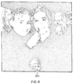
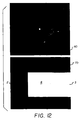
- Fig. 1 is a grayscale image 10 of a color image illustrating two pairs of redeyes 20.
- a color digital image is input to the software program residing on a computer system, such computer systems being well known in the art.
- the code values of the digital image are preferably proportional to the log of the amount of exposure of the film used to capture the image by the original scene S2.
- the program begins by identifying all separate continuous skin colored regions in the image S4.
- step S4 there is illustrated a detail flowchart of step S4 in Fig. 2.
- the next step is to build a three-dimensional histogram.
- the L , S , and T code values are quantized by dividing them by 8.0 x sqrt(3), 2.0, and 2.0, respectively S4b. These quantized code values are referred to as L , S , and T .
- Each combination of L , S , and T values is referred to as a "bin" of the histogram.
- the value of the histogram H ( L , S , T ) S4c is equal to the number of pixels in the image that have quantized code values of L , S , and T .
- An alternative way of stating this is that the histogram tell us the number of pixels in the image that fall into each bin. This number is referred to as the value of the bin.
- the histogram is smoothed S4d by replacing the value of each bin by a weighted average of the value of that bin and the values of immediate neighboring bins.
- the peak values in the histogram are found S4e and each bin in the histogram is assigned S4f the peak value that is located closest to it.
- a peak is assigned to each pixel in the color image S4g.
- the single band image in which a pixel's code value is equal to the number of the peak that it was assigned to is referred to as the segmented image.
- a unique number is assigned to all such regions in the segmented image S4h. The numbers are sequentially assigned starting with 1 for the region with the greatest number of pixels.
- the single band image in which code values correspond to the label of the region that the pixel belongs to is called the labeled image.
- the program decides which of the continuous regions in the segmented image corresponds to a region in the color image that has a color that is typical of human skin.
- the average L , S , and T code values of each region is calculated and, based on this, each region is assigned a score P skin S4i.
- a high value of P skin indicates that the region is of a color that is typical of human skin.
- a low number indicates that the color of the region is atypical of skin.
- Regions for which P skin exceeds a threshold T skin of 0.10 are referred to as skin-colored regions S4j.
- One final step is necessary to associate each face in the color image with a single skin colored region.
- the process described above will often result in a single face being associated with more that one skin colored region because due to complexion, shadows, and etc., the color of the face is not uniform.
- Two skin colored regions are merged into a single skin colored region if two conditions are satisfied S4k.
- the first condition requires that the two regions be inter-connected.
- a pixel in region i has a connection to region j if a pixel belonging to region j is one of the eight nearest neighbor pixels.
- a function Q(i , j) is calculated which is proportional to the number of connections between pixels of region i and j .
- the function is normalized so that Q(i , i) is equal to 1.0.
- MinMergerFraction regions i and j will be merged into a single region if the second condition is also satisfied, for example a threshold of 0.005 may be used.
- the process of merging skin colored regions begins with the smallest region which, if the two conditions are satisfied, is merged with a larger region. If region i is merged with larger region j it may then happen that region j gets merged with an even larger region k . When this occurs regions i , j , and k are merged into a single region. Note that regions i and k may be merged together even though the above two conditions are not satisfied for these two regions. They are merged because of their mutual connection to region j .
- the result of skin color detection is a map of the skin colored regions in the color image S41. Areas that are not skin colored are given a code value of zero. The separate continuous skin colored regions are numbered consecutively in order of decreasing region size beginning with the number 1.
- Fig. 4 shows a map of the skin colored regions in Fig. 1.
- a sub-map of each skin colored region is formed by cutting out from the skin map (Fig. 4) the smallest rectangular section that contains all of that skin region S6.
- skin region 30b in Fig. 5 corresponds to skin region 30a in Fig. 4.
- Fig. 5 shows the map of each separate continuous skin colored regions as an individual sub-map.
- the column and row of the skin map that correspond to the top left corner of the sub-map are referred to as Col cutout and Row cutout , respectively.
- code values of 255 (white) indicates that the pixel is located at a position at which skin color is present.
- a code value of 0 (black) indicates the absence of skin color.
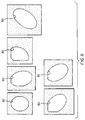
- an ellipse 35 is fitted S8 to the individual skin color sub-maps found in step S6 (Fig. 5).
- a method of fitting an ellipse to a binary image is described in Computer and Robot Vision, Volume I, by Robert M. Haralick and Linda G. Shapiro, Addison-Wesley (1992), pp. 639-658.
- a human face is approximately elliptical. Therefore, if the skin color sub-map is of a human face, then the ellipse should fit the skin color map well and the minor axis of the ellipse should approximately equal the width of the face.
- N is the number of skin colored pixels (code value 255) in the map
- N out is the number of skin colored pixels that fall outside the ellipse
- N in is the number of skin colored pixels that are inside the ellipse
- A is the number of pixels in the ellipse.
- A is also referred to as the area of the ellipse. If all of the skin colored pixels are in the ellipse and the number of skin colored pixels equals the area of the ellipse then Fit is equal to one and the fit is perfect.
- AspectRatio D major D minor where D major is the major axis of the ellipse and D minor is the minor axis in pixels. If AspectRatio is greater than MaxAspectRatio which is set equal to 3.0 the skin colored region corresponds to an object in the image that is too long and thin to be a face. The program determines that the skin colored region is not a face and does not process it further S10.
- the map potentially indicates the position of a face.
- S prescale AimEyeDistance x FaceWidthEyeDistanceRatio D minor where AimEyeDistance which is set equal to 75 pixels is the desired distance between eyes, and FaceWidthEyeDistanceRatio which is set equal to 2.0 is the ratio between the width and eye distance for a typical face. If S prescale is less than MinPrescale 0.10 or greater than MaxPrescale 1.50 the skin colored region is not processed further S10.
- the next step is to cut-out from the color image a sub-color-image that corresponds exactly to the location of the sub-map S12. If the minor axis of the ellipse is approximately equal to the width of the face then the distance between the eyes in the face should be close to AimEyeDistance .
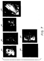
- Fig. 7 shows the sub-color-images 40 after they have been resized in this manner. It is instructive to note that Fig. 7 is illustrated as a gray scale drawing, although the actual image is a color image.
- Fig. 8 shows the ellipses 50 that correspond to each of these sub-color-images that have also been resized S14.
- the sub-color-images 40 are processed so as to identify small red features.
- Redeyes in the new image will appear as small elliptical areas of high code value possibly with a small low code value region in the middle that is due to glint in the pupil.
- the affect of glint is removed by performing a gray scale morphological closing S16b using a W _ close x W _ close kernel, for example a 3 x 3 kernal although other sizes may also be used.
- Gray scale morphological operations are disclosed in Image Analysis and Mathematical Morphology Volume 1 , by Jean Serra, Academic Press (1982), pp. 424-478.
- the small regions of high code value are removed by a gray scale morphological opening operation using a W _ open x W _ open kernel, for example a 5 x 5 kernal although other sizes may also be used S16c.
- the opened image is then subtracted from the closed image in order to form a residual image S16d.
- This image shows what was in the opened image, but not in the closed image. Namely, small regions of high code value which correspond to small red features in the sub-color-image.
- the residual image is smoothed S16e with a linear filter having the kernel shown below. 1 2 1 2 4 2 1 2 1 For each pixel in the smoothed residual image, a 7x7 window centered at that pixel is examined.
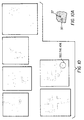
- Fig. 10 shows the peaks 37 for all of the sub-color-images in Fig. 7. After all the peaks in the smoothed residual image have been found the individual peaks are examined S16g. First, if a pixel has been classified as a peak and a neighboring pixel that is west, north-west, north, or north-east of this pixel has also been classified as a peak, the peak is eliminated S16h.
- a pixel that has been classified as a peak is a candidate redeye pixel. It is possible however that the location of the peak coincides with glint in the pupil and not the red defect. For this reason, pixels within a distance GlintRadius equal to 2 from the peak are examined S16i. The candidate redeye pixel is moved to the nearby pixel with the highest color score P color which will be defined below.
- the candidate redeye pixel is used as a seed to grow a continuous region of pixels of simular color. If the number of pixels in the region is less than MinSize or greater than MaxSize the region is not of a size that is characteristic of a redeye defect and the candidate redeye pixel is eliminated S16j.
- the result of the above processing is a map of candidate redeye pixels for each sub-color-image S16k.
- the ellipses in Fig. 8 are approximate maps of the region in the corresponding sub-color-images in Fig. 7 that have been identified as potentially being a face. Therefore, only the candidate redeye pixels that fall inside of the ellipse are considered in the next phase eye detection which is outlined in Fig. 11.
- the purpose of eye detection is to determine whether the candidate redeye pixels are indeed part of an eye.
- the eye detection procedure requires a monotone version of the color image S18.
- This monocolor version of the color image will be referred to as the luminance image.
- the eye detection procedure S20 in Fig. 2 is based on the process of template matching. It facilitates understanding to note that any image of an eye can be used a the template.
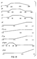
- the top image 60 in Fig. 12 shows a left-eye template.
- the bottom image 70 shows a division of the template into zones. Zone 1 is the eyebrow region. Zones 2 and 3 are the left and right sides of the eye, respectively. Zone 4 includes the pupil and iris. Zone 0 is not used.
- the eye template was taken from an image in which the distance between the eyes is TemplateEyeDistance equal to 306 pixels and the tilt of the two eyes is close to zero.
- the estimation of the face width from the minor axis of the ellipse will not always be accurate. Also, the eyes may be tilted. For this reason starting with the original left-eye template and the zone map, a collection of left-eye, right-eye (mirror image of left-eye), and zone maps are generated that span a range of sizes and orientations S22.
- the original eye template and zone map are resized from a factor of S 0 x Narrow to S 0 x Wide in increments of SStep .
- Preferred values of Narrow , Wide , and Sstep are 1.5, 0.50, and 0.05, respectively.
- a series of tilted templates and zone maps are generated that range from - MaxTilt degrees (clock-wise tilt) to MaxTilt degrees in increments of TStep degrees S22.
- the preferred value of MaxTilt is 30 degrees and of TStep is 2.0 degrees.
- step S20 of Fig. 2 A pair of candidate redeye pixels are considered that hypothetically belong to a left and right redeye pair S20a.
- an ensemble of eye templates and zone map templates were made that span a range of resize factors from S 0 x Narrow to S 0 x Wide with resolution SStep and with a tilt from - MaxTilt degrees to MaxTilt degrees with a resolution TStep .
- the left-eye template, right-eye template, and zone map that most closely match the value of S pair and Tilt for the pair of candidate redeye pixels is used in the correlation step that follows. If S pair or Tilt are outside of this range, this pair is not processed further S20c.
- the next step is to determine if the region around the redeye pixel matches an eye. This is done by performing a correlation of the left-eye template with a region around the left candidate redeye pixel and the right-eye template with a region around the right candidate redeye pixel of the luminance image S20d.
- One step of the correlation process is to match up pixels of the template and luminance image and calculate the product of their code values.
- the center of the template images corresponds to the center of the eye. Since the candidate redeye pixels are close, but not necessarily at the center of an eye, we perform the correlation several times with the center of the template matched to all of the pixels within a square that extends a distance LookAround equal to 3 about the candidate redeye pixel.
- the correlation is performed separately for zones 1 through 4 of the template (see Fig. 12). These correlations are referred to as Cz1 , Cz2 , Cz3 , and Cz4 .
- an overall correlation is calculated for a region that consists of the sum of zones 1 through 4. This overall correlation is referred to as C .
- the pixel in the square around the candidate redeye pixel with the highest value of the overall correlation C is the best guess of the center of an eye which contains the candidate redeye pixel. This pixel is referred to as the eye-center pixel. Both the left and right candidate redeye pixels have an associated eye-center pixel.
- the template image is denoted by the function ⁇ ( p , l ) where p is the column number and l is the row number.
- the number of columns and rows in the template is w and h , respectively.
- the center of the eye template is approximately the location of the center of the eye.
- a zone of the template is correlated with the luminance image which we denote by ⁇ ( p , l ) at column p o and row l o by calculating the product ⁇ given by.
- ⁇ 1 N z p ⁇ z / ⁇ z ⁇ ( p + p o - w /2-1,/+/ o - h /2-1) ⁇ ( p,l )
- p ⁇ Z means that column p is in zone Z
- l ⁇ Z means that row l is in zone Z
- N z is the number of pixels in the zone.
- M ⁇ 1 N z p ⁇ z / ⁇ z ⁇ ( p,l ) is also calculated.
- the standard deviation of the template in zone Z is calculated according to the equation.
- ⁇ ⁇ 1 N z p ⁇ z / ⁇ z ( ⁇ ( p,l )- M ⁇ ) 2 1/2
- the values of C , C z1 , C z2 , C z3 , and C z4 for the eye-center pixels are used in the calculation of a score that is a measure of the likelihood that the pair of candidate redeye pixels are part of a redeye defect in the sub-color-image S20e.
- Each of the correlations are used as a variable in an associated scoring function that ranges from 0.0 to 1.0.
- the scoring function associated with the overall correlation C which we refer to as pC(C) is 0.0 if the value of C for an eye-center pixel indicates that it is very unlikely that the pixel actually is located at the center of an eye.
- Scores are defined based on these scoring functions which will be combined later into an overall score for a candidate redeye pair.
- the score P zone associated with the zone correlations is a weighted average of the zone correlation scoring functions. It has been found that the correlation in zone 4 (the pupil) is a much more reliable indicator of the presence of an eye than the other zones. For this reason it is given more weight than other zones. Typical we set the weight W equal to 6.0.
- P zone pC z 1 ( C Z1 )+ pC z 2 ( C z 2 )+ pC z 3 ( C z 3 )+ WpC z 4 ( C z 4 ) W +3
- the color of the candidate redeye pixel must be indicative of a real redeye defect.
- code values of the candidate redeye pixel is convert into luminance ( Lum ), hue ( Hue ), and saturation ( Sat ) values.
- the value of Lum for a pixel ranges from zero to the highest possible code value.
- the hue is defined as in Computer Graphics Principles and Practice 2nd ed.
- the color red is shifted to a hue angle of 120 degrees.
- the value of Hue may range from 0 to 360 degrees.
- P eye P corr P zone P sigma P color Its value is in the range of 0.0 to 1.0.
- the pair of candidate redeye pixels for which P pair is the largest is referred to as the best pair of candidate redeye pixels S20f. If P pair exceeds the threshold MinEyeScore equal to 0.05, then the program processes further. Otherwise, the program concludes that a pair of redeyes is not present in the sub-color-image S20g.
- One method of confirming that a pair of redeyes has indeed been located is to use the fact that a human face is approximately symmetric about a line that bisects the face S24 in Fig. 2.
- the sub-color-image is rotated so that the tilt of a line connecting the best pair of candidate redeye pixels is equal to zero.
- an image centered at the midpoint between the eyes is cut-out of the sub-color-image. This image has a width of 1.5 times the distance between the candidate redeye pixels and a height equal to a quarter of its width. This image is in turn cut in half.
- the left half-image we refer to as E x left (p,l) and the right half-image by E x right (p,l) where the superscript x refers to a band of the color image.
- E r left (p,l) refers to the red band of the image.
- the columns in the right half-image are inverted (the first column becomes the last column, etc.) so that it becomes a mirror image of itself.
- C x sym ⁇ x sym - M x left M x right ⁇ x left ⁇ x right where M x left and M x right are the mean code values of band x of the half-images and ⁇ x left and ⁇ x right are the standard deviations.
- the final score P is simply the product of P sym and P pair .
- P P sym P pair If this score which may range between 0.0 and 1.0 exceeds a threshold MinScore which is set equal to 0.05 S26, then the candidate redeye pixel pair is assumed to mark the location of a pair of redeye defects in the resized sub-color-image.
Abstract
Description
- The invention relates generally to the field of digital image processing and, more particular to a method for detecting redeye in digital images.
- When flash illumination is used for the capture of an image sometimes the pupils of people in the image appear red. This is caused by light from the flash unit entering the pupil, multiply reflecting off the retina, and finally exiting back through the pupil. Because light is partially absorbed by capillaries in the retina the pupil appears red in the image. This phenomena is referred to as "redeye." The probability of redeye being observed increases the closer the flash unit is to the optical axis of the lens. Therefore, redeye is commonly observed in images captured by a small camera with an integral flash unit.
- Commonly assigned US-A-5,432,863 describes a user-interactive method for the detection of objects in an image that have the color characteristic of redeye. This method automatically detects candidate redeye pixels based on shape coloration and brightness.
- Although the presently known method of detecting redeye is satisfactory, it is not without drawbacks. The method of US-A-5,432,863 does not determine whether the candidate pixels are located in a face or are part of a human eye.
- Consequently, a need exists for detecting redeye that overcomes the above-described drawbacks.
- The present invention is directed to overcoming one or more of the problems set forth above. Briefly summarized, according to one aspect of the present invention, the invention resides in a computer program product for detecting eye color defects of a subject in an image due to flash illumination, comprising : a computer readable storage medium having a computer program stored thereon for performing the steps of: (a) detecting skin colored regions in a digital image; (b) searching the skin colored regions for groups of pixels with color characteristic of redeye defect; and (c) correcting color of the pixels based on a location of redeye defect found in step (b).
- It is an object of the present invention to provide a method for automatically detecting redeye defects.
- It is an object of the present invention to provide a method for determining whether candidate redeye defects are part of the human face.
- It is also an object of the present invention to provide a method for determining whether candidate redeye defects are part of the human eye.
- These and other aspects, objects, features and advantages of the present invention will be more clearly understood and appreciated from a review of the following detailed description of the preferred embodiments and appended claims, and by reference to the accompanying drawings.
- Fig. 1 is a diagram illustrating redeye;
- Fig. 2 is an overview flowchart of the software program of the present invention;
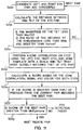
- Fig. 3 is a detailed flowchart of the continuous skin colored region determination portion of Fig. 2;
- Fig. 4 is a binary representation of Fig. 1 illustrating skin-colored regions;
- Fig. 5 is a detailed viewed of the individual continuos colored regions of Fig. 4;
- Fig. 6 is a diagram of ellipses fitted to the views of Fig. 5;
- Fig. 7 illustrates resized candidate face regions;
- Fig. 8 is a diagram of resized ellipses corresponding to the candidate face regions fitted to Fig. 7;
- Fig. 9 is a detailed flowchart of the candidate redeye determination portion of Fig. 2;
- Fig. 10 illustrates the candidate redeye defects of Fig. 7;
- Fig. 11 is a detailed flowchart of the eye detection portion of Fig. 2;
- Fig. 12 illustrates an eye template, and zone map; and
- Fig. 13 illustrates scoring functions of the present invention.
-
- In the following description, the present invention will be described in the preferred embodiment as a software program. Those skilled in the art will readily recognize that the equivalent of such software may also be constructed in hardware.
- Fig. 1 is a
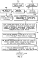
grayscale image 10 of a color image illustrating two pairs ofredeyes 20. - Referring to Fig. 2, there is illustrated an overview flowchart of the present invention. A color digital image is input to the software program residing on a computer system, such computer systems being well known in the art. The code values of the digital image are preferably proportional to the log of the amount of exposure of the film used to capture the image by the original scene S2. The program begins by identifying all separate continuous skin colored regions in the image S4.
- Referring to Fig. 3, there is illustrated a detail flowchart of step S4 in Fig. 2. First, the red, green, and blue values of the color image are converted into LST color space S4a using the relations:
- The next step is to build a three-dimensional histogram. In order to reduce the size of the histogram, first, the L, S, and T code values are quantized by dividing them by 8.0 x sqrt(3), 2.0, and 2.0, respectively S4b. These quantized code values are referred to as L, S

- The histogram is smoothed S4d by replacing the value of each bin by a weighted average of the value of that bin and the values of immediate neighboring bins. Next, the peak values in the histogram are found S4e and each bin in the histogram is assigned S4f the peak value that is located closest to it. Finally, since each pixel in the color image has been assigned to a bin of the histogram and each bin has been assigned to a peak, a peak is assigned to each pixel in the color image S4g. The single band image in which a pixel's code value is equal to the number of the peak that it was assigned to is referred to as the segmented image.
- Continuous regions in the segmented image that have the same code value are likely to correspond to an object or part of an object in the color image. A unique number (label) is assigned to all such regions in the segmented image S4h. The numbers are sequentially assigned starting with 1 for the region with the greatest number of pixels. The single band image in which code values correspond to the label of the region that the pixel belongs to is called the labeled image.
- The program then decides which of the continuous regions in the segmented image corresponds to a region in the color image that has a color that is typical of human skin. The average L, S, and T code values of each region is calculated and, based on this, each region is assigned a score Pskin S4i. A high value of Pskin indicates that the region is of a color that is typical of human skin. Alternatively, a low number indicates that the color of the region is atypical of skin. Regions for which Pskin exceeds a threshold Tskin of 0.10 are referred to as skin-colored regions S4j.
- One final step is necessary to associate each face in the color image with a single skin colored region. The process described above will often result in a single face being associated with more that one skin colored region because due to complexion, shadows, and etc., the color of the face is not uniform. Two skin colored regions are merged into a single skin colored region if two conditions are satisfied S4k. The first condition requires that the two regions be inter-connected. A pixel in region i has a connection to region j if a pixel belonging to region j is one of the eight nearest neighbor pixels. A function Q(i, j) is calculated which is proportional to the number of connections between pixels of region i and j. The function is normalized so that Q(i, i) is equal to 1.0. If Q(i, j) exceeds the threshold MinMergerFraction regions i and j will be merged into a single region if the second condition is also satisfied, for example a threshold of 0.005 may be used. The second condition is that the distance between the colors of the regions i and j given by
- The process of merging skin colored regions begins with the smallest region which, if the two conditions are satisfied, is merged with a larger region. If region i is merged with larger region j it may then happen that region j gets merged with an even larger region k. When this occurs regions i, j, and k are merged into a single region. Note that regions i and k may be merged together even though the above two conditions are not satisfied for these two regions. They are merged because of their mutual connection to region j.
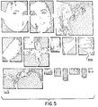
- The result of skin color detection is a map of the skin colored regions in the color image S41. Areas that are not skin colored are given a code value of zero. The separate continuous skin colored regions are numbered consecutively in order of decreasing region size beginning with the
number 1. Fig. 4 shows a map of the skin colored regions in Fig. 1. - Referring to Fig. 2, and as illustrated in Fig. 5, a sub-map of each skin colored region is formed by cutting out from the skin map (Fig. 4) the smallest rectangular section that contains all of that skin region S6. For example,
skin region 30b in Fig. 5 corresponds to skinregion 30a in Fig. 4. Fig. 5 shows the map of each separate continuous skin colored regions as an individual sub-map. The column and row of the skin map that correspond to the top left corner of the sub-map are referred to as Colcutout and Rowcutout , respectively. In the sub-map code values of 255 (white) indicates that the pixel is located at a position at which skin color is present. A code value of 0 (black) indicates the absence of skin color. - Referring to Fig. 2, and as illustrated in Fig. 6, in the next step an
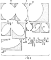
ellipse 35 is fitted S8 to the individual skin color sub-maps found in step S6 (Fig. 5). A method of fitting an ellipse to a binary image is described in Computer and Robot Vision, Volume I, by Robert M. Haralick and Linda G. Shapiro, Addison-Wesley (1992), pp. 639-658. A human face is approximately elliptical. Therefore, if the skin color sub-map is of a human face, then the ellipse should fit the skin color map well and the minor axis of the ellipse should approximately equal the width of the face. A measure of the fit of an ellipse to the skin color sub-map is given by - Another indication of whether the skin color sub-map is of a face is the aspect ratio of the ellipse AspectRatio which is given by
- If the skin sub-map has an acceptable degree of fit to an ellipse and the ellipse has an acceptable aspect ratio, the map potentially indicates the position of a face. Next, we calculate a resize factor Sprescale which is given by the following equation
images 40 after they have been resized in this manner. It is instructive to note that Fig. 7 is illustrated as a gray scale drawing, although the actual image is a color image. Fig. 8 shows theellipses 50 that correspond to each of these sub-color-images that have also been resized S14. In practice, it is desirable to add extra rows and columns to the edges of the resized sub-color-images and sub-maps so that when these images are processed further an out-of-bounds pixel is not addressed. The top and bottom of the images are padded with Pad rows and the left and right side with Pad columns. - Now that skin colored regions that have the shape of a face have been identified, the location of candidate redeyes need to be identified S16, which is illustrated in detail in Fig. 9. Now referring to Fig. 9, the sub-color-
images 40 are processed so as to identify small red features. The program begins by defining a new single band image S16a with pixel values X given by - Redeyes in the new image will appear as small elliptical areas of high code value possibly with a small low code value region in the middle that is due to glint in the pupil. The affect of glint is removed by performing a gray scale morphological closing S16b using a W_close x W_close kernel, for example a 3 x 3 kernal although other sizes may also be used. Gray scale morphological operations are disclosed in Image Analysis and
Mathematical Morphology Volume 1, by Jean Serra, Academic Press (1982), pp. 424-478. Next, the small regions of high code value are removed by a gray scale morphological opening operation using a W_open x W_open kernel, for example a 5 x 5 kernal although other sizes may also be used S16c. The opened image is then subtracted from the closed image in order to form a residual image S16d. This image shows what was in the opened image, but not in the closed image. Namely, small regions of high code value which correspond to small red features in the sub-color-image. Next, the residual image is smoothed S16e with a linear filter having the kernel shown below.1 2 1 2 4 2 1 2 1 peaks 37 for all of the sub-color-images in Fig. 7. After all the peaks in the smoothed residual image have been found the individual peaks are examined S16g. First, if a pixel has been classified as a peak and a neighboring pixel that is west, north-west, north, or north-east of this pixel has also been classified as a peak, the peak is eliminated S16h. - A pixel that has been classified as a peak is a candidate redeye pixel. It is possible however that the location of the peak coincides with glint in the pupil and not the red defect. For this reason, pixels within a distance GlintRadius equal to 2 from the peak are examined S16i. The candidate redeye pixel is moved to the nearby pixel with the highest color score Pcolor which will be defined below.
- Next, the candidate redeye pixel is used as a seed to grow a continuous region of pixels of simular color. If the number of pixels in the region is less than MinSize or greater than MaxSize the region is not of a size that is characteristic of a redeye defect and the candidate redeye pixel is eliminated S16j.
- The result of the above processing is a map of candidate redeye pixels for each sub-color-image S16k. The ellipses in Fig. 8 are approximate maps of the region in the corresponding sub-color-images in Fig. 7 that have been identified as potentially being a face. Therefore, only the candidate redeye pixels that fall inside of the ellipse are considered in the next phase eye detection which is outlined in Fig. 11.
- Referring back to Fig. 2, the purpose of eye detection is to determine whether the candidate redeye pixels are indeed part of an eye. The eye detection procedure requires a monotone version of the color image S18. The green band of the color image is used after the contrast is increased by transforming the green pixel code values using the equation
G - The eye detection procedure S20 in Fig. 2 is based on the process of template matching. It facilitates understanding to note that any image of an eye can be used a the template. The
top image 60 in Fig. 12 shows a left-eye template. Thebottom image 70 shows a division of the template into zones.Zone 1 is the eyebrow region.Zones 2 and 3 are the left and right sides of the eye, respectively.Zone 4 includes the pupil and iris. Zone 0 is not used. The eye template was taken from an image in which the distance between the eyes is TemplateEyeDistance equal to 306 pixels and the tilt of the two eyes is close to zero. As discussed above, a pair of redeyes in the resized color sub-images should be approximately a distance AimEyeDistance (75 pixels) apart. Therefore, in order for the template to be of the proper size to match an eye is must be resized by a factor of - In practice, the estimation of the face width from the minor axis of the ellipse will not always be accurate. Also, the eyes may be tilted. For this reason starting with the original left-eye template and the zone map, a collection of left-eye, right-eye (mirror image of left-eye), and zone maps are generated that span a range of sizes and orientations S22. The original eye template and zone map are resized from a factor of S0 x Narrow to S 0 x Wide in increments of SStep. Preferred values of Narrow, Wide, and Sstep are 1.5, 0.50, and 0.05, respectively. In order to accommodate tilt for each resize factor, a series of tilted templates and zone maps are generated that range from -MaxTilt degrees (clock-wise tilt) to MaxTilt degrees in increments of TStep degrees S22. The preferred value of MaxTilt is 30 degrees and of TStep is 2.0 degrees.
- Referring to Fig. 11, a detailed flowchart of step S20 of Fig. 2 is shown. A pair of candidate redeye pixels are considered that hypothetically belong to a left and right redeye pair S20a. The scale of the eye relative to the original eye template is related to the distance S20b between the candidate redeye pixel pair by the equation
- As discussed above, an ensemble of eye templates and zone map templates were made that span a range of resize factors from S 0 x Narrow to S 0 x Wide with resolution SStep and with a tilt from -MaxTilt degrees to MaxTilt degrees with a resolution TStep. The left-eye template, right-eye template, and zone map that most closely match the value of Spair and Tilt for the pair of candidate redeye pixels is used in the correlation step that follows. If Spair or Tilt are outside of this range, this pair is not processed further S20c.
- After an eye template has been selected the next step is to determine if the region around the redeye pixel matches an eye. This is done by performing a correlation of the left-eye template with a region around the left candidate redeye pixel and the right-eye template with a region around the right candidate redeye pixel of the luminance image S20d. One step of the correlation process is to match up pixels of the template and luminance image and calculate the product of their code values. The center of the template images corresponds to the center of the eye. Since the candidate redeye pixels are close, but not necessarily at the center of an eye, we perform the correlation several times with the center of the template matched to all of the pixels within a square that extends a distance LookAround equal to 3 about the candidate redeye pixel. The correlation is performed separately for
zones 1 through 4 of the template (see Fig. 12). These correlations are referred to as Cz1, Cz2, Cz3, and Cz4. In addition, an overall correlation is calculated for a region that consists of the sum ofzones 1 through 4. This overall correlation is referred to as C. The pixel in the square around the candidate redeye pixel with the highest value of the overall correlation C is the best guess of the center of an eye which contains the candidate redeye pixel. This pixel is referred to as the eye-center pixel. Both the left and right candidate redeye pixels have an associated eye-center pixel. - The correlation process is now explained in detail. The template image is denoted by the function Φ (p,l) where p is the column number and l is the row number. The number of columns and rows in the template is w and h, respectively. The center of the eye template is approximately the location of the center of the eye. A zone of the template is correlated with the luminance image which we denote by Γ(p, l) at column p o and row l o by calculating the product Π given by.
- Using the quantities defined above the correlation of the luminance image with the template in zone Z is given by the relation
- The values of C, Cz1 , Cz2 , Cz3 , and Cz4 for the eye-center pixels are used in the calculation of a score that is a measure of the likelihood that the pair of candidate redeye pixels are part of a redeye defect in the sub-color-image S20e. Each of the correlations are used as a variable in an associated scoring function that ranges from 0.0 to 1.0. For example, the scoring function associated with the overall correlation C which we refer to as pC(C) is 0.0 if the value of C for an eye-center pixel indicates that it is very unlikely that the pixel actually is located at the center of an eye. On the other hand, if the value of C is in a range that is typical of the correlation of the template with an eye then pC(C) is 1.0. Otherwise pC(C) takes on an intermediate value. The scoring function pC(C) and other scoring functions described below are shown in Fig. 13.
- Scores are defined based on these scoring functions which will be combined later into an overall score for a candidate redeye pair. The following equation defines a score Pcorr related to the overall correlation C as simply
W + 3 - It has been found that the standard deviation of the luminance image σΓ that was calculated in the process of calculating the overall correlation C is a good indicator if the feature in the luminance image centered at the eye-center pixel is actually an eye. For instance, if σΓ is very low than the feature is of too low contrast to be an eye. With this in mind we define a score associated with σΓ by
- Finally, the color of the candidate redeye pixel must be indicative of a real redeye defect. For this calculation the red, green, and blue, code values of the candidate redeye pixel is convert into luminance (Lum), hue (Hue), and saturation (Sat) values. Luminance is calculated as follows
- The result is a score Peye which indicates the likelihood that a candidate redeye pixel is actually part of a redeye defect in the image. This score is defined by
- It is important to minimize the possibility that the best pair of candidate redeye pixels that are not part of a pair of eyes with a redeye defect in the color image be incorrectly classified. One method of confirming that a pair of redeyes has indeed been located is to use the fact that a human face is approximately symmetric about a line that bisects the face S24 in Fig. 2. In order to do this, the sub-color-image is rotated so that the tilt of a line connecting the best pair of candidate redeye pixels is equal to zero. Next, an image centered at the midpoint between the eyes is cut-out of the sub-color-image. This image has a width of 1.5 times the distance between the candidate redeye pixels and a height equal to a quarter of its width. This image is in turn cut in half. The left half-image we refer to as Ex left(p,l) and the right half-image by Ex right(p,l) where the superscript x refers to a band of the color image. For example, Er left(p,l) refers to the red band of the image. The columns in the right half-image are inverted (the first column becomes the last column, etc.) so that it becomes a mirror image of itself. A correlation of Ex left(p,l) and Ex right(p,l) is performed by first calculating the sum of products
- The final score P is simply the product of Psym and Ppair .
- Finally, the positions of the left and right redeye defects in the original color image are calculated based on the position of the left and right candidate redeye pixels in the resized sub-color-image using the relations
- It sometimes happens that two different skin colored regions after being fitted to an ellipse will overlap or be very close together. This may result in the same redeye pair being found twice or the detection of two redeye pairs that are too close together for both to be truly a pair of redeyes. For this reason, after all the redeye pairs in the color image have been located it is determined if any two pairs have redeye locations less than MinInterpairEyeDistance equal to 20 pixels apart. If this is the case the pair with the lower score is eliminated S30.
Claims (9)
- A computer program product for detecting eye color defects of a subject in an image due to flash illumination, comprising : a computer readable storage medium having a computer program stored thereon for performing the steps of:(a) detecting skin colored regions in a digital image;(b) searching the skin colored regions for groups of pixels with color characteristic of redeye defect; and(c) correcting color of the pixels based on a location of redeye defect found in step (b).
- The computer program product as in claim 1, wherein step (a) includes:(a1) segmenting the digital image into continuous regions of uniform color and assigning a score indicating probability that the region corresponds to skin for forming a candidate skin region.
- The computer program product as in claim 2, wherein step (a1) includes merging two or more candidate skin regions based on their similarity of color and degree of connectivity.
- The computer program product as in claim 2, wherein step (a1) includes determining probability that the candidate region is a face based on its shape.
- A computer program product for detecting eye color defects of a subject in an image due to flash illumination, comprising : a computer readable storage medium having a computer program stored thereon for performing the steps of:(a) searching of a digital image for groups of pixels with color characteristic of redeye defect for forming candidate redeye defect;(b) determining whether the candidate redeye defect is located at a position that matches an eye; and(c) correcting color of the pixels based on a location of redeye defect found in step (b).
- The computer program product as in claim 5, wherein the match of step (b) further includes determining for a pair of candidate redeye defects the size and tilt expected of an eye based on distance between and the tilt of the pair of candidate redeye defects.
- The computer program product as in claim 5, wherein the match of step (b) includes correlating a region around the candidate redeye defects with an eye template.
- The computer program product as in claim 7, wherein the match of step (b) includes correlating the region around the candidate redeye defects with individual zones of the eye template.
- A computer program product for detecting eye color defects of a subject in an image due to flash illumination, comprising : a computer readable storage medium having a computer program stored thereon for performing the steps of:(a) detecting skin colored regions in a digital image;(b) searching the skin colored regions for groups of pixels with color characteristic of redeye defect for forming a candidate redeye defect;(c) determining whether the candidate redeye defect is located at a position that matches an eye; and(d) correcting color of the pixels based on a location of the redeye defect.
Applications Claiming Priority (2)
| Application Number | Priority Date | Filing Date | Title |
|---|---|---|---|
| US08/919,560 US6292574B1 (en) | 1997-08-29 | 1997-08-29 | Computer program product for redeye detection |
| US919560 | 1997-08-29 |
Publications (2)
| Publication Number | Publication Date |
|---|---|
| EP0899686A2 true EP0899686A2 (en) | 1999-03-03 |
| EP0899686A3 EP0899686A3 (en) | 2000-06-14 |
Family
ID=25442312
Family Applications (1)
| Application Number | Title | Priority Date | Filing Date |
|---|---|---|---|
| EP98202756A Withdrawn EP0899686A3 (en) | 1997-08-29 | 1998-08-17 | A computer program product for redeye detection |
Country Status (3)
| Country | Link |
|---|---|
| US (1) | US6292574B1 (en) |
| EP (1) | EP0899686A3 (en) |
| JP (1) | JP4428737B2 (en) |
Cited By (10)
| Publication number | Priority date | Publication date | Assignee | Title |
|---|---|---|---|---|
| WO2000067204A2 (en) * | 1999-05-03 | 2000-11-09 | Pictuality, Inc. | Image analysis process |
| EP1229493A2 (en) * | 2000-12-19 | 2002-08-07 | Eastman Kodak Company | Multi-mode digital image processing method for detecting eyes |
| EP1255225A2 (en) * | 2001-05-01 | 2002-11-06 | Eastman Kodak Company | Method for detecting eye and mouth positions in a digital image |
| EP1271394A2 (en) * | 2001-06-19 | 2003-01-02 | Eastman Kodak Company | Method for automatically locating eyes in an image |
| EP1293933A1 (en) * | 2001-09-03 | 2003-03-19 | Agfa-Gevaert AG | Method for automatically detecting red-eye defects in photographic image data |
| EP1365357A1 (en) * | 2001-02-19 | 2003-11-26 | NEC Corporation | Device for creating image feature from image having any shape |
| AU769886B2 (en) * | 2000-03-01 | 2004-02-05 | Canon Kabushiki Kaisha | Segmenting an image |
| EP1530158A2 (en) * | 2003-11-05 | 2005-05-11 | Omron Corporation | Pupil color estimating device |
| US6980691B2 (en) | 2001-07-05 | 2005-12-27 | Corel Corporation | Correction of “red-eye” effects in images |
| EP2051210A1 (en) * | 2007-10-17 | 2009-04-22 | Qualcomm Incorporated | Effective red eye removal in digital images without face detection |
Families Citing this family (114)
| Publication number | Priority date | Publication date | Assignee | Title |
|---|---|---|---|---|
| US6786420B1 (en) | 1997-07-15 | 2004-09-07 | Silverbrook Research Pty. Ltd. | Data distribution mechanism in the form of ink dots on cards |
| US6618117B2 (en) | 1997-07-12 | 2003-09-09 | Silverbrook Research Pty Ltd | Image sensing apparatus including a microcontroller |
| US7714889B2 (en) * | 1997-07-15 | 2010-05-11 | Silverbrook Research Pty Ltd | Digital camera using exposure information for image processing |
| US7551201B2 (en) | 1997-07-15 | 2009-06-23 | Silverbrook Research Pty Ltd | Image capture and processing device for a print on demand digital camera system |
| US6879341B1 (en) | 1997-07-15 | 2005-04-12 | Silverbrook Research Pty Ltd | Digital camera system containing a VLIW vector processor |
| US20040160524A1 (en) * | 1997-07-15 | 2004-08-19 | Kia Silverbrook | Utilising exposure information for image processing in a digital image camera |
| AUPO850597A0 (en) | 1997-08-11 | 1997-09-04 | Silverbrook Research Pty Ltd | Image processing method and apparatus (art01a) |
| US7246897B2 (en) * | 1997-07-15 | 2007-07-24 | Silverbrook Research Pty Ltd | Media cartridge for inkjet printhead |
| US6690419B1 (en) | 1997-07-15 | 2004-02-10 | Silverbrook Research Pty Ltd | Utilising eye detection methods for image processing in a digital image camera |
| AUPO802797A0 (en) | 1997-07-15 | 1997-08-07 | Silverbrook Research Pty Ltd | Image processing method and apparatus (ART54) |
| AUPO799997A0 (en) | 1997-07-15 | 1997-08-07 | Silverbrook Research Pty Ltd | Image processing method and apparatus (ART10) |
| US7110024B1 (en) | 1997-07-15 | 2006-09-19 | Silverbrook Research Pty Ltd | Digital camera system having motion deblurring means |
| US6624848B1 (en) | 1997-07-15 | 2003-09-23 | Silverbrook Research Pty Ltd | Cascading image modification using multiple digital cameras incorporating image processing |
| US6985207B2 (en) | 1997-07-15 | 2006-01-10 | Silverbrook Research Pty Ltd | Photographic prints having magnetically recordable media |
| US7077515B2 (en) | 1997-07-15 | 2006-07-18 | Silverbrook Research Pty Ltd | Media cartridge for inkjet printhead |
| US7593058B2 (en) * | 1997-07-15 | 2009-09-22 | Silverbrook Research Pty Ltd | Digital camera with integrated inkjet printer having removable cartridge containing ink and media substrate |
| US7551202B2 (en) * | 1997-07-15 | 2009-06-23 | Silverbrook Research Pty Ltd | Digital camera with integrated inkjet printer |
| US7705891B2 (en) | 1997-07-15 | 2010-04-27 | Silverbrook Research Pty Ltd | Correction of distortions in digital images |
| US7352394B1 (en) | 1997-10-09 | 2008-04-01 | Fotonation Vision Limited | Image modification based on red-eye filter analysis |
| US7042505B1 (en) * | 1997-10-09 | 2006-05-09 | Fotonation Ireland Ltd. | Red-eye filter method and apparatus |
| US7630006B2 (en) | 1997-10-09 | 2009-12-08 | Fotonation Ireland Limited | Detecting red eye filter and apparatus using meta-data |
| US7738015B2 (en) | 1997-10-09 | 2010-06-15 | Fotonation Vision Limited | Red-eye filter method and apparatus |
| JPH11175699A (en) * | 1997-12-12 | 1999-07-02 | Fuji Photo Film Co Ltd | Picture processor |
| US6631208B1 (en) * | 1998-05-29 | 2003-10-07 | Fuji Photo Film Co., Ltd. | Image processing method |
| JP2000048184A (en) * | 1998-05-29 | 2000-02-18 | Canon Inc | Method for processing image, and method for extracting facial area and device therefor |
| AUPP400998A0 (en) | 1998-06-10 | 1998-07-02 | Canon Kabushiki Kaisha | Face detection in digital images |
| AUPP702098A0 (en) | 1998-11-09 | 1998-12-03 | Silverbrook Research Pty Ltd | Image creation method and apparatus (ART73) |
| AUPQ056099A0 (en) | 1999-05-25 | 1999-06-17 | Silverbrook Research Pty Ltd | A method and apparatus (pprint01) |
| US7092122B2 (en) * | 2000-07-18 | 2006-08-15 | Fuji Photo Film Co., Ltd. | Image processing device and method |
| JP2002043200A (en) * | 2000-07-24 | 2002-02-08 | Mitsubishi Electric Corp | Method and device for detecting abnormal cause |
| US6728401B1 (en) * | 2000-08-17 | 2004-04-27 | Viewahead Technology | Red-eye removal using color image processing |
| US6711286B1 (en) * | 2000-10-20 | 2004-03-23 | Eastman Kodak Company | Method for blond-hair-pixel removal in image skin-color detection |
| US6920237B2 (en) * | 2000-12-19 | 2005-07-19 | Eastman Kodak Company | Digital image processing method and computer program product for detecting human irises in an image |
| US20020081003A1 (en) * | 2000-12-27 | 2002-06-27 | Sobol Robert E. | System and method for automatically enhancing graphical images |
| US6895112B2 (en) * | 2001-02-13 | 2005-05-17 | Microsoft Corporation | Red-eye detection based on red region detection with eye confirmation |
| US20020172419A1 (en) * | 2001-05-15 | 2002-11-21 | Qian Lin | Image enhancement using face detection |
| JP4778158B2 (en) * | 2001-05-31 | 2011-09-21 | オリンパス株式会社 | Image selection support device |
| US7133070B2 (en) * | 2001-09-20 | 2006-11-07 | Eastman Kodak Company | System and method for deciding when to correct image-specific defects based on camera, scene, display and demographic data |
| US7058209B2 (en) * | 2001-09-20 | 2006-06-06 | Eastman Kodak Company | Method and computer program product for locating facial features |
| US7155058B2 (en) * | 2002-04-24 | 2006-12-26 | Hewlett-Packard Development Company, L.P. | System and method for automatically detecting and correcting red eye |
| JP2004053324A (en) * | 2002-07-17 | 2004-02-19 | Denso Corp | Collision safety controller for automobile |
| US7035461B2 (en) * | 2002-08-22 | 2006-04-25 | Eastman Kodak Company | Method for detecting objects in digital images |
| US7035462B2 (en) * | 2002-08-29 | 2006-04-25 | Eastman Kodak Company | Apparatus and method for processing digital images having eye color defects |
| US7397969B2 (en) * | 2002-08-30 | 2008-07-08 | Fujifilm Corporation | Red eye compensation method, image processing apparatus and method for implementing the red eye compensation method, as well as printing method and printer |
| US20040093432A1 (en) * | 2002-11-07 | 2004-05-13 | Eastman Kodak Company | Method and system for conducting image processing from a mobile client device |
| US7116820B2 (en) * | 2003-04-28 | 2006-10-03 | Hewlett-Packard Development Company, Lp. | Detecting and correcting red-eye in a digital image |
| US7224850B2 (en) * | 2003-05-13 | 2007-05-29 | Microsoft Corporation | Modification of red-eye-effect in digital image |
| DE60314851D1 (en) * | 2003-05-19 | 2007-08-23 | St Microelectronics Sa | Image processing method for numerical images with exposure correction by detection of skin areas of the object |
| US20040239968A1 (en) * | 2003-06-02 | 2004-12-02 | Gondek Jay S. | Color correction in images |
| US8254674B2 (en) | 2004-10-28 | 2012-08-28 | DigitalOptics Corporation Europe Limited | Analyzing partial face regions for red-eye detection in acquired digital images |
| US7574016B2 (en) | 2003-06-26 | 2009-08-11 | Fotonation Vision Limited | Digital image processing using face detection information |
| US7792970B2 (en) | 2005-06-17 | 2010-09-07 | Fotonation Vision Limited | Method for establishing a paired connection between media devices |
| US7920723B2 (en) | 2005-11-18 | 2011-04-05 | Tessera Technologies Ireland Limited | Two stage detection for photographic eye artifacts |
| US7587085B2 (en) | 2004-10-28 | 2009-09-08 | Fotonation Vision Limited | Method and apparatus for red-eye detection in an acquired digital image |
| US7536036B2 (en) | 2004-10-28 | 2009-05-19 | Fotonation Vision Limited | Method and apparatus for red-eye detection in an acquired digital image |
| US7970182B2 (en) | 2005-11-18 | 2011-06-28 | Tessera Technologies Ireland Limited | Two stage detection for photographic eye artifacts |
| US7689009B2 (en) | 2005-11-18 | 2010-03-30 | Fotonation Vision Ltd. | Two stage detection for photographic eye artifacts |
| US8036458B2 (en) | 2007-11-08 | 2011-10-11 | DigitalOptics Corporation Europe Limited | Detecting redeye defects in digital images |
| US8170294B2 (en) | 2006-11-10 | 2012-05-01 | DigitalOptics Corporation Europe Limited | Method of detecting redeye in a digital image |
| US9412007B2 (en) | 2003-08-05 | 2016-08-09 | Fotonation Limited | Partial face detector red-eye filter method and apparatus |
| US20050031224A1 (en) * | 2003-08-05 | 2005-02-10 | Yury Prilutsky | Detecting red eye filter and apparatus using meta-data |
| US8520093B2 (en) | 2003-08-05 | 2013-08-27 | DigitalOptics Corporation Europe Limited | Face tracker and partial face tracker for red-eye filter method and apparatus |
| US7333653B2 (en) * | 2003-08-29 | 2008-02-19 | Hewlett-Packard Development Company, L.P. | Detecting and correcting redeye in an image |
| US7454040B2 (en) * | 2003-08-29 | 2008-11-18 | Hewlett-Packard Development Company, L.P. | Systems and methods of detecting and correcting redeye in an image suitable for embedded applications |
| US7835572B2 (en) * | 2003-09-30 | 2010-11-16 | Sharp Laboratories Of America, Inc. | Red eye reduction technique |
| US7684642B2 (en) * | 2004-03-03 | 2010-03-23 | Eastman Kodak Company | Correction of redeye defects in images of humans |
| JP2005316958A (en) * | 2004-03-30 | 2005-11-10 | Fuji Photo Film Co Ltd | Red eye detection device, method, and program |
| JP4505362B2 (en) * | 2004-03-30 | 2010-07-21 | 富士フイルム株式会社 | Red-eye detection apparatus and method, and program |
| US7852377B2 (en) * | 2004-04-16 | 2010-12-14 | Arcsoft, Inc. | Automatic red eye removal |
| JP4496465B2 (en) * | 2004-04-23 | 2010-07-07 | ノーリツ鋼機株式会社 | Red-eye correction method, program, and apparatus for implementing the method |
| US20050248664A1 (en) * | 2004-05-07 | 2005-11-10 | Eastman Kodak Company | Identifying red eye in digital camera images |
| JP4574249B2 (en) * | 2004-06-29 | 2010-11-04 | キヤノン株式会社 | Image processing apparatus and method, program, and imaging apparatus |
| JP4599110B2 (en) * | 2004-07-30 | 2010-12-15 | キヤノン株式会社 | Image processing apparatus and method, imaging apparatus, and program |
| EP1774466A4 (en) * | 2004-07-30 | 2009-10-21 | Canon Kk | Image processing method and apparatus, image sensing apparatus, and program |
| US8000505B2 (en) * | 2004-09-01 | 2011-08-16 | Eastman Kodak Company | Determining the age of a human subject in a digital image |
| US7623707B2 (en) * | 2004-09-15 | 2009-11-24 | Adobe Systems Incorporated | Hierarchically locating a feature in a digital image |
| US8081818B2 (en) * | 2004-09-15 | 2011-12-20 | Adobe Systems Incorporated | Locating a feature in a digital image |
| US7444017B2 (en) * | 2004-11-10 | 2008-10-28 | Eastman Kodak Company | Detecting irises and pupils in images of humans |
| JP4405942B2 (en) * | 2005-06-14 | 2010-01-27 | キヤノン株式会社 | Image processing apparatus and method |
| JP4498224B2 (en) * | 2005-06-14 | 2010-07-07 | キヤノン株式会社 | Image processing apparatus and method |
| JP4420459B2 (en) * | 2005-06-14 | 2010-02-24 | キヤノン株式会社 | Image processing apparatus and method |
| US20070036438A1 (en) * | 2005-08-15 | 2007-02-15 | Lexmark International, Inc. | Methods and systems for identifying red eye pairs |
| US7747071B2 (en) * | 2005-10-27 | 2010-06-29 | Hewlett-Packard Development Company, L.P. | Detecting and correcting peteye |
| US7599577B2 (en) | 2005-11-18 | 2009-10-06 | Fotonation Vision Limited | Method and apparatus of correcting hybrid flash artifacts in digital images |
| GB2432659A (en) * | 2005-11-28 | 2007-05-30 | Pixology Software Ltd | Face detection in digital images |
| JP4712563B2 (en) * | 2006-01-16 | 2011-06-29 | 富士フイルム株式会社 | Face detection method, apparatus and program |
| EP1987475A4 (en) | 2006-02-14 | 2009-04-22 | Fotonation Vision Ltd | Automatic detection and correction of non-red eye flash defects |
| EP2033142B1 (en) | 2006-06-12 | 2011-01-26 | Tessera Technologies Ireland Limited | Advances in extending the aam techniques from grayscale to color images |
| US8064694B2 (en) * | 2006-06-21 | 2011-11-22 | Hewlett-Packard Development Company, L.P. | Nonhuman animal integument pixel classification |
| US20080170778A1 (en) * | 2007-01-15 | 2008-07-17 | Huitao Luo | Method and system for detection and removal of redeyes |
| US8055067B2 (en) | 2007-01-18 | 2011-11-08 | DigitalOptics Corporation Europe Limited | Color segmentation |
| WO2008109708A1 (en) | 2007-03-05 | 2008-09-12 | Fotonation Vision Limited | Red eye false positive filtering using face location and orientation |
| US20090024687A1 (en) * | 2007-07-20 | 2009-01-22 | Thomas Quigley | Method and system for formatting returned result from remote processing resource in wireless system |
| US7755802B2 (en) * | 2007-08-24 | 2010-07-13 | Eastman Kodak Company | Toner-based noise reduction in electrostatography |
| US8031970B2 (en) * | 2007-08-27 | 2011-10-04 | Arcsoft, Inc. | Method of restoring closed-eye portrait photo |
| JP2009080522A (en) * | 2007-09-25 | 2009-04-16 | Mitsubishi Electric Corp | Object image recognition device |
| US8503818B2 (en) | 2007-09-25 | 2013-08-06 | DigitalOptics Corporation Europe Limited | Eye defect detection in international standards organization images |
| US8212864B2 (en) | 2008-01-30 | 2012-07-03 | DigitalOptics Corporation Europe Limited | Methods and apparatuses for using image acquisition data to detect and correct image defects |
| US8446494B2 (en) * | 2008-02-01 | 2013-05-21 | Hewlett-Packard Development Company, L.P. | Automatic redeye detection based on redeye and facial metric values |
| US8331666B2 (en) * | 2008-03-03 | 2012-12-11 | Csr Technology Inc. | Automatic red eye artifact reduction for images |
| US8081254B2 (en) | 2008-08-14 | 2011-12-20 | DigitalOptics Corporation Europe Limited | In-camera based method of detecting defect eye with high accuracy |
| JP4912374B2 (en) * | 2008-09-10 | 2012-04-11 | 富士フイルム株式会社 | Face illustration drawing generation method and face illustration drawing generation apparatus |
| JP4640490B2 (en) * | 2008-10-24 | 2011-03-02 | コニカミノルタビジネステクノロジーズ株式会社 | Program for correcting red eye in image, recording medium, and red eye correction method |
| US8818091B2 (en) | 2011-03-21 | 2014-08-26 | Apple Inc. | Red-eye removal using multiple recognition channels |
| US8837827B2 (en) | 2011-03-21 | 2014-09-16 | Apple Inc. | Red-eye removal using multiple recognition channels |
| US8786735B2 (en) * | 2011-03-21 | 2014-07-22 | Apple Inc. | Red-eye removal using multiple recognition channels |
| US8837822B2 (en) | 2011-03-21 | 2014-09-16 | Apple Inc. | Red-eye removal using multiple recognition channels |
| US8837785B2 (en) * | 2011-03-21 | 2014-09-16 | Apple Inc. | Red-eye removal using multiple recognition channels |
| US8571271B2 (en) | 2011-05-26 | 2013-10-29 | Microsoft Corporation | Dual-phase red eye correction |
| US8811683B2 (en) | 2011-06-02 | 2014-08-19 | Apple Inc. | Automatic red-eye repair using multiple recognition channels |
| US9041954B2 (en) | 2011-06-07 | 2015-05-26 | Hewlett-Packard Development Company, L.P. | Implementing consistent behavior across different resolutions of images |
| US8970902B2 (en) | 2011-09-19 | 2015-03-03 | Hewlett-Packard Development Company, L.P. | Red-eye removal systems and method for variable data printing (VDP) workflows |
| US9378564B2 (en) * | 2013-03-01 | 2016-06-28 | Colormodules Inc. | Methods for color correcting digital images and devices thereof |
| JP6188453B2 (en) | 2013-06-28 | 2017-08-30 | キヤノン株式会社 | Image processing apparatus, image processing method, and program |
Citations (1)
| Publication number | Priority date | Publication date | Assignee | Title |
|---|---|---|---|---|
| EP0635972A2 (en) | 1993-07-19 | 1995-01-25 | Eastman Kodak Company | Automated detection and correction of eye color defects due to flash illumination |
Family Cites Families (25)
| Publication number | Priority date | Publication date | Assignee | Title |
|---|---|---|---|---|
| JPS60217353A (en) * | 1984-04-13 | 1985-10-30 | Fuji Photo Film Co Ltd | Detection for flesh color |
| US5130935A (en) * | 1986-03-31 | 1992-07-14 | Canon Kabushiki Kaisha | Color image processing apparatus for extracting image data having predetermined color information from among inputted image data and for correcting inputted image data in response to the extracted image data |
| US5128711A (en) * | 1989-04-28 | 1992-07-07 | Fuji Photo Film Co., Ltd. | Apparatus for recording position information of principal image and method of detecting principal image |
| US5150433A (en) * | 1989-12-01 | 1992-09-22 | Eastman Kodak Company | Histogram/variance mechanism for detecting presence of an edge within block of image data |
| US5130789A (en) * | 1989-12-13 | 1992-07-14 | Eastman Kodak Company | Localized image recoloring using ellipsoid boundary function |
| US5089976A (en) * | 1990-07-18 | 1992-02-18 | Friends Of The Ucsd Library, Inc. | Color normalization process |
| JP2522859B2 (en) * | 1990-12-14 | 1996-08-07 | 日産自動車株式会社 | Eye position detection device |
| JP3030126B2 (en) * | 1991-07-15 | 2000-04-10 | 三洋電機株式会社 | Image processing method |
| JP3346799B2 (en) * | 1992-08-24 | 2002-11-18 | 株式会社日立製作所 | Sign language interpreter |
| US5680481A (en) * | 1992-05-26 | 1997-10-21 | Ricoh Corporation | Facial feature extraction method and apparatus for a neural network acoustic and visual speech recognition system |
| JP3036285B2 (en) * | 1993-03-05 | 2000-04-24 | ミノルタ株式会社 | Red eye position detector |
| JP3387071B2 (en) * | 1993-04-20 | 2003-03-17 | ソニー株式会社 | Image identification apparatus and method |
| JP3358033B2 (en) * | 1993-06-25 | 2002-12-16 | オリンパス光学工業株式会社 | Image correction device and image correction method |
| JP2757756B2 (en) * | 1993-12-24 | 1998-05-25 | 日本電気株式会社 | Eye corner detection device |
| JP3395344B2 (en) * | 1994-04-20 | 2003-04-14 | 日産自動車株式会社 | Image processing device and doze alarm device using the same |
| JPH08138024A (en) * | 1994-11-04 | 1996-05-31 | Konica Corp | Picture direction discriminating method |
| JPH08149480A (en) * | 1994-11-25 | 1996-06-07 | Matsushita Electric Ind Co Ltd | Image encoding device |
| US5724456A (en) * | 1995-03-31 | 1998-03-03 | Polaroid Corporation | Brightness adjustment of images using digital scene analysis |
| DE69507594T2 (en) * | 1995-03-31 | 1999-09-02 | Hitachi Europ Ltd | Image processing method for determining facial features |
| JP3355068B2 (en) * | 1995-07-14 | 2002-12-09 | 三菱電機株式会社 | Face image processing device |
| JPH0950528A (en) * | 1995-08-09 | 1997-02-18 | Nippon Telegr & Teleph Corp <Ntt> | Person detector |
| JP3510040B2 (en) | 1996-03-26 | 2004-03-22 | コニカミノルタホールディングス株式会社 | Image processing method |
| JP2907120B2 (en) * | 1996-05-29 | 1999-06-21 | 日本電気株式会社 | Red-eye detection correction device |
| US6009209A (en) | 1997-06-27 | 1999-12-28 | Microsoft Corporation | Automated removal of red eye effect from a digital image |
| US6016354A (en) | 1997-10-23 | 2000-01-18 | Hewlett-Packard Company | Apparatus and a method for reducing red-eye in a digital image |
-
1997
- 1997-08-29 US US08/919,560 patent/US6292574B1/en not_active Expired - Lifetime
-
1998
- 1998-08-17 EP EP98202756A patent/EP0899686A3/en not_active Withdrawn
- 1998-08-28 JP JP24327598A patent/JP4428737B2/en not_active Expired - Lifetime
Patent Citations (2)
| Publication number | Priority date | Publication date | Assignee | Title |
|---|---|---|---|---|
| EP0635972A2 (en) | 1993-07-19 | 1995-01-25 | Eastman Kodak Company | Automated detection and correction of eye color defects due to flash illumination |
| US5432863A (en) | 1993-07-19 | 1995-07-11 | Eastman Kodak Company | Automated detection and correction of eye color defects due to flash illumination |
Non-Patent Citations (2)
| Title |
|---|
| OIAN CHEN ET AL.: "Real-time face detection", PROCEEDINGS OF THE SECOND ASIAN CONFERENCE ON COMPUTER VISION, pages 479 - 483 |
| QIAN CHEN ET AL., PROCEEDINGS OF THE SECOND ASIAN CONFERENCE ON COMPUTER VISION, pages 479 - 483 |
Cited By (22)
| Publication number | Priority date | Publication date | Assignee | Title |
|---|---|---|---|---|
| WO2000067204A3 (en) * | 1999-05-03 | 2001-03-01 | Pictuality Inc | Image analysis process |
| WO2000067204A2 (en) * | 1999-05-03 | 2000-11-09 | Pictuality, Inc. | Image analysis process |
| AU769886B2 (en) * | 2000-03-01 | 2004-02-05 | Canon Kabushiki Kaisha | Segmenting an image |
| EP1229493A3 (en) * | 2000-12-19 | 2004-12-15 | Eastman Kodak Company | Multi-mode digital image processing method for detecting eyes |
| EP1229493A2 (en) * | 2000-12-19 | 2002-08-07 | Eastman Kodak Company | Multi-mode digital image processing method for detecting eyes |
| US7697753B2 (en) | 2001-02-19 | 2010-04-13 | Nec Corporation | Device for creating image feature from image having any shape |
| EP1365357A4 (en) * | 2001-02-19 | 2009-11-25 | Nec Corp | Device for creating image feature from image having any shape |
| EP1365357A1 (en) * | 2001-02-19 | 2003-11-26 | NEC Corporation | Device for creating image feature from image having any shape |
| US7092554B2 (en) | 2001-05-01 | 2006-08-15 | Eastman Kodak Company | Method for detecting eye and mouth positions in a digital image |
| EP1255225A3 (en) * | 2001-05-01 | 2004-03-31 | Eastman Kodak Company | Method for detecting eye and mouth positions in a digital image |
| EP1255225A2 (en) * | 2001-05-01 | 2002-11-06 | Eastman Kodak Company | Method for detecting eye and mouth positions in a digital image |
| EP1271394A3 (en) * | 2001-06-19 | 2004-02-11 | Eastman Kodak Company | Method for automatically locating eyes in an image |
| US6895103B2 (en) | 2001-06-19 | 2005-05-17 | Eastman Kodak Company | Method for automatically locating eyes in an image |
| EP1271394A2 (en) * | 2001-06-19 | 2003-01-02 | Eastman Kodak Company | Method for automatically locating eyes in an image |
| US6980691B2 (en) | 2001-07-05 | 2005-12-27 | Corel Corporation | Correction of “red-eye” effects in images |
| EP1293933A1 (en) * | 2001-09-03 | 2003-03-19 | Agfa-Gevaert AG | Method for automatically detecting red-eye defects in photographic image data |
| US7590284B2 (en) | 2003-11-05 | 2009-09-15 | Omron Corporation | Pupil color estimating device |
| EP1530158A3 (en) * | 2003-11-05 | 2006-05-24 | Omron Corporation | Pupil color estimating device |
| EP1530158A2 (en) * | 2003-11-05 | 2005-05-11 | Omron Corporation | Pupil color estimating device |
| EP2051210A1 (en) * | 2007-10-17 | 2009-04-22 | Qualcomm Incorporated | Effective red eye removal in digital images without face detection |
| WO2009052402A1 (en) * | 2007-10-17 | 2009-04-23 | Qualcomm Incorporated | Effective red eye removal in digital images without face detection |
| US8391596B2 (en) | 2007-10-17 | 2013-03-05 | Qualcomm Incorporated | Effective red eye removal in digital images without face detection |
Also Published As
| Publication number | Publication date |
|---|---|
| EP0899686A3 (en) | 2000-06-14 |
| US6292574B1 (en) | 2001-09-18 |
| JPH11136498A (en) | 1999-05-21 |
| JP4428737B2 (en) | 2010-03-10 |
Similar Documents
| Publication | Publication Date | Title |
|---|---|---|
| EP0899686A2 (en) | A computer program product for redeye detection | |
| EP0961225A2 (en) | A computer program product for redeye detection | |
| US7035461B2 (en) | Method for detecting objects in digital images | |
| US7444017B2 (en) | Detecting irises and pupils in images of humans | |
| US7116820B2 (en) | Detecting and correcting red-eye in a digital image | |
| US5864630A (en) | Multi-modal method for locating objects in images | |
| US5805745A (en) | Method for locating a subject's lips in a facial image | |
| US7403654B2 (en) | Enhanced automatic red eye removal | |
| US5995639A (en) | Apparatus for identifying person | |
| US6320973B2 (en) | Animal identification system based on irial granule analysis | |
| US7454040B2 (en) | Systems and methods of detecting and correcting redeye in an image suitable for embedded applications | |
| EP1229493A2 (en) | Multi-mode digital image processing method for detecting eyes | |
| US8295593B2 (en) | Method of detecting red-eye objects in digital images using color, structural, and geometric characteristics | |
| EP1271394A2 (en) | Method for automatically locating eyes in an image | |
| US7852377B2 (en) | Automatic red eye removal | |
| EP0932114A2 (en) | A method of and apparatus for detecting a face-like region and observer tracking display | |
| US8285002B2 (en) | Image processing apparatus and method, image sensing apparatus, and program | |
| US20080170778A1 (en) | Method and system for detection and removal of redeyes | |
| EP1970859B1 (en) | Detecting method and detecting system for positions of face parts | |
| US6829383B1 (en) | Stochastic adjustment of differently-illuminated images | |
| JP3510040B2 (en) | Image processing method | |
| CN108876845A (en) | The determination method and apparatus at Fresnel line center | |
| KR20010013501A (en) | Method and apparatus for performing robust recognition |
Legal Events
| Date | Code | Title | Description |
|---|---|---|---|
| PUAI | Public reference made under article 153(3) epc to a published international application that has entered the european phase |
Free format text: ORIGINAL CODE: 0009012 |
|
| AK | Designated contracting states |
Kind code of ref document: A2 Designated state(s): DE FR GB |
|
| AX | Request for extension of the european patent |
Free format text: AL;LT;LV;MK;RO;SI |
|
| PUAL | Search report despatched |
Free format text: ORIGINAL CODE: 0009013 |
|
| AK | Designated contracting states |
Kind code of ref document: A3 Designated state(s): AT BE CH CY DE DK ES FI FR GB GR IE IT LI LU MC NL PT SE |
|
| AX | Request for extension of the european patent |
Free format text: AL;LT;LV;MK;RO;SI |
|
| RIC1 | Information provided on ipc code assigned before grant |
Free format text: 7G 06T 7/00 A, 7H 04N 1/62 B |
|
| 17P | Request for examination filed |
Effective date: 20001207 |
|
| AKX | Designation fees paid |
Free format text: DE FR GB |
|
| 17Q | First examination report despatched |
Effective date: 20071017 |
|
| RAP1 | Party data changed (applicant data changed or rights of an application transferred) |
Owner name: INTELLECTUAL VENTURES FUND 83 LLC |
|
| STAA | Information on the status of an ep patent application or granted ep patent |
Free format text: STATUS: THE APPLICATION IS DEEMED TO BE WITHDRAWN |
|
| 18D | Application deemed to be withdrawn |
Effective date: 20140301 |