EP0900574B1 - Handle for steerable DMR catheter - Google Patents
Handle for steerable DMR catheter Download PDFInfo
- Publication number
- EP0900574B1 EP0900574B1 EP98307122A EP98307122A EP0900574B1 EP 0900574 B1 EP0900574 B1 EP 0900574B1 EP 98307122 A EP98307122 A EP 98307122A EP 98307122 A EP98307122 A EP 98307122A EP 0900574 B1 EP0900574 B1 EP 0900574B1
- Authority
- EP
- European Patent Office
- Prior art keywords
- catheter
- tip section
- control handle
- lumen
- catheter body
- Prior art date
- Legal status (The legal status is an assumption and is not a legal conclusion. Google has not performed a legal analysis and makes no representation as to the accuracy of the status listed.)
- Expired - Lifetime
Links
Images


Classifications
-
- A—HUMAN NECESSITIES
- A61—MEDICAL OR VETERINARY SCIENCE; HYGIENE
- A61M—DEVICES FOR INTRODUCING MEDIA INTO, OR ONTO, THE BODY; DEVICES FOR TRANSDUCING BODY MEDIA OR FOR TAKING MEDIA FROM THE BODY; DEVICES FOR PRODUCING OR ENDING SLEEP OR STUPOR
- A61M25/00—Catheters; Hollow probes
- A61M25/01—Introducing, guiding, advancing, emplacing or holding catheters
- A61M25/0105—Steering means as part of the catheter or advancing means; Markers for positioning
- A61M25/0133—Tip steering devices
- A61M25/0147—Tip steering devices with movable mechanical means, e.g. pull wires
-
- A—HUMAN NECESSITIES
- A61—MEDICAL OR VETERINARY SCIENCE; HYGIENE
- A61B—DIAGNOSIS; SURGERY; IDENTIFICATION
- A61B18/00—Surgical instruments, devices or methods for transferring non-mechanical forms of energy to or from the body
- A61B18/18—Surgical instruments, devices or methods for transferring non-mechanical forms of energy to or from the body by applying electromagnetic radiation, e.g. microwaves
- A61B18/20—Surgical instruments, devices or methods for transferring non-mechanical forms of energy to or from the body by applying electromagnetic radiation, e.g. microwaves using laser
- A61B18/22—Surgical instruments, devices or methods for transferring non-mechanical forms of energy to or from the body by applying electromagnetic radiation, e.g. microwaves using laser the beam being directed along or through a flexible conduit, e.g. an optical fibre; Couplings or hand-pieces therefor
- A61B18/24—Surgical instruments, devices or methods for transferring non-mechanical forms of energy to or from the body by applying electromagnetic radiation, e.g. microwaves using laser the beam being directed along or through a flexible conduit, e.g. an optical fibre; Couplings or hand-pieces therefor with a catheter
-
- A—HUMAN NECESSITIES
- A61—MEDICAL OR VETERINARY SCIENCE; HYGIENE
- A61B—DIAGNOSIS; SURGERY; IDENTIFICATION
- A61B18/00—Surgical instruments, devices or methods for transferring non-mechanical forms of energy to or from the body
- A61B18/04—Surgical instruments, devices or methods for transferring non-mechanical forms of energy to or from the body by heating
- A61B18/12—Surgical instruments, devices or methods for transferring non-mechanical forms of energy to or from the body by heating by passing a current through the tissue to be heated, e.g. high-frequency current
- A61B18/14—Probes or electrodes therefor
- A61B18/1492—Probes or electrodes therefor having a flexible, catheter-like structure, e.g. for heart ablation
-
- A—HUMAN NECESSITIES
- A61—MEDICAL OR VETERINARY SCIENCE; HYGIENE
- A61B—DIAGNOSIS; SURGERY; IDENTIFICATION
- A61B17/00—Surgical instruments, devices or methods, e.g. tourniquets
- A61B17/00234—Surgical instruments, devices or methods, e.g. tourniquets for minimally invasive surgery
- A61B2017/00238—Type of minimally invasive operation
- A61B2017/00243—Type of minimally invasive operation cardiac
- A61B2017/00247—Making holes in the wall of the heart, e.g. laser Myocardial revascularization
-
- A—HUMAN NECESSITIES
- A61—MEDICAL OR VETERINARY SCIENCE; HYGIENE
- A61B—DIAGNOSIS; SURGERY; IDENTIFICATION
- A61B17/00—Surgical instruments, devices or methods, e.g. tourniquets
- A61B17/00234—Surgical instruments, devices or methods, e.g. tourniquets for minimally invasive surgery
- A61B2017/00292—Surgical instruments, devices or methods, e.g. tourniquets for minimally invasive surgery mounted on or guided by flexible, e.g. catheter-like, means
- A61B2017/003—Steerable
-
- A—HUMAN NECESSITIES
- A61—MEDICAL OR VETERINARY SCIENCE; HYGIENE
- A61B—DIAGNOSIS; SURGERY; IDENTIFICATION
- A61B18/00—Surgical instruments, devices or methods for transferring non-mechanical forms of energy to or from the body
- A61B2018/00315—Surgical instruments, devices or methods for transferring non-mechanical forms of energy to or from the body for treatment of particular body parts
- A61B2018/00345—Vascular system
- A61B2018/00351—Heart
- A61B2018/00392—Transmyocardial revascularisation
-
- A—HUMAN NECESSITIES
- A61—MEDICAL OR VETERINARY SCIENCE; HYGIENE
- A61B—DIAGNOSIS; SURGERY; IDENTIFICATION
- A61B5/00—Measuring for diagnostic purposes; Identification of persons
- A61B5/24—Detecting, measuring or recording bioelectric or biomagnetic signals of the body or parts thereof
- A61B5/25—Bioelectric electrodes therefor
- A61B5/279—Bioelectric electrodes therefor specially adapted for particular uses
- A61B5/28—Bioelectric electrodes therefor specially adapted for particular uses for electrocardiography [ECG]
- A61B5/283—Invasive
- A61B5/287—Holders for multiple electrodes, e.g. electrode catheters for electrophysiological study [EPS]
-
- A—HUMAN NECESSITIES
- A61—MEDICAL OR VETERINARY SCIENCE; HYGIENE
- A61M—DEVICES FOR INTRODUCING MEDIA INTO, OR ONTO, THE BODY; DEVICES FOR TRANSDUCING BODY MEDIA OR FOR TAKING MEDIA FROM THE BODY; DEVICES FOR PRODUCING OR ENDING SLEEP OR STUPOR
- A61M25/00—Catheters; Hollow probes
- A61M25/01—Introducing, guiding, advancing, emplacing or holding catheters
- A61M25/0105—Steering means as part of the catheter or advancing means; Markers for positioning
- A61M25/0133—Tip steering devices
- A61M25/0147—Tip steering devices with movable mechanical means, e.g. pull wires
- A61M2025/015—Details of the distal fixation of the movable mechanical means
Definitions
- the present invention relates to steerable catheters which are particularly useful in direct myocardial revascularization procedures.
- Direct myocardial revascularization also referred to as percutaneous myocardial revascularization
- DMR Direct myocardial revascularization
- percutaneous myocardial revascularization is a technique that allows physicians to treat patients who have sustained a myocardial infraction by burning channels in the myocardium that has been determined to be ischemic heart tissue.
- the channels which are burned by a laser, allow for angiogenesis, i.e., the formation of blood vessels.
- DMR catheters require the physician to have more control and information than other catheters having an optic fiber, such as ablation catheters.
- Aita et al. generally describes a DMR catheter.
- the present invention is directed to an improved DMR catheter which allows the physician to have greater control and obtain more information than the catheter described in Aita el al.
- US-A-5462544 describes a mapping and lasing catheter including a manipulating handle for deflecting the distal end of the catheter, and an optic fibre for optical or visual control of the end. However, it provides no guidance as to how to protect the optic fibre within the manipulating handle, in which there can be moving parts that could damage the optic fibre.
- the present invention therefore, provides a design of DMR catheter that additionally protects the optic fibre in the catheter.
- the present invention provides a steerable direct myocardial revascularization catheter as defined in claim 1 that can be used to treat ischemic heart tissue.
- the steerable DMR catheter comprises a catheter body or shaft, a tip section attached to the distal end of the catheter body and a control handle attached to the proximal end of the catheter body.
- a puller wire is anchored at its proximal end in the control handle and extends through a lumen in the catheter body and a lumen in the tip section and is anchored at or about the distal end of the tip section. Manipulation of the control handle results in deflection of the tip section.
- An optic fiber suitable for transmission of laser energy extends through the control handle, catheter body and tip section, the distal end of the optic fiber being generally flush with the distal end surface of the tip section.
- the proximal end of the optic fiber extends proximally from the control handle to a suitable connector which connects the optic fiber to a source of laser energy.
- the optic fiber is used to transmit laser energy for creating channels, i.e. blind holes, in the heart tissue which induces revascularization.
- the tip section of the DMR catheter comprises an electromagnetic sensor.
- the electromagnetic sensor is connected to a circuit board by means of a sensor cable which extends proximally through the tip section, catheter body, and control handle.
- the circuit board is preferably housed in the handle. Signals from the circuit board are transmitted through a cable to a computer and monitor.
- the electromagnetic sensor allows a physician to create a visual representation of the heart chamber and to view the location of the sensor, and therefore the catheter tip, within the chamber.
- the DMR catheter comprises a tip electrode and one or more ring electrodes spaced proximally from the tip electrode. Each electrode is connected by means of electrode lead wires which extend through the tip section, catheter body and control handle to an appropriate connector, and from there, to a suitable monitor.
- the tip and ring electrodes allow the electrical activity of the heart tissue to be mapped.
- the DMR catheter comprises both an electromagnetic sensor within the tip section and a tip electrode and one or more ring electrodes.
- This combination allows a physician to map the electrical activity of the heart wall of a particular chamber, e.g., the left ventricle, by means of the tip and ring electrodes to determine ischemic areas and simultaneously to record the precise location of the tip section within the heart by means of the electromagnetic sensor to create a three-dimensional representation of the heart chamber which is displayed visually on a monitor.
- the tip section is moved to that area and deflected to allow the optic fiber to be generally normal to the heart wall, and then laser energy is transmitted onto the heart tissue for creating a channel within the heart tissue.
- the optic fiber comprises a protective jacket, preferably made out of aluminum.
- the optic fiber extends through the control handle and catheter body and into the tip section which carries a tip electrode.
- the optic fiber extends through an optic fiber lumen in the tip electrode, the distal end of the optic fiber being flush with the distal face of the tip electrode.
- the aluminum jacket is removed from the distal portion of the optic fiber which extends through the tip electrode. This removal avoids the possibility that particles of the aluminum jacket may break free into the heart, especially during laser transmission, which could result in a stroke. This removal also prevents the possibility of an electrical short between the aluminum jacket and the tip electrode, which could result in the patient receiving a lethally high voltage during laser transmission.
- a DMR catheter having an infusion tube which extends from the proximal end of the catheter body through a lumen in the catheter body and into the tip section.
- the distal end of the infusion tube is open at the distal end of the tip section at a position adjacent the optic fiber so that fluids, including drugs to induce angiogenesis, may be passed through the catheter to the heart tissue.
- the DMR catheter comprises an infusion tube and a tip electrode having an infusion passage adjacent the optic fiber lumen.
- the infusion tube is connected to, preferably inserted into, the infusion passage in the tip electrode so that fluids passing through the infusion tube will enter and pass through the infusion passage in the tip electrode and to the heart tissue.
- the proximal end of the infusion tube terminates in a luer hub or the like.
- the catheter body or shaft comprises a construction which exhibits improved torsional stability, resulting in improved tip control while minimizing wall thickness.
- the catheter body comprises a single central lumen and is formed by a tubular outer wall of polyurethane or nylon with a braided stainless steel mesh imbedded in the outer wall.
- the inner surface of the outer wall is lined with a stiffening tube, preferably made of polyimide or the like.
- a polyimide stiffening tube provides improved torsional stability while at the same time minimizing the wall thickness of the catheter. This, in turn, maximizes the diameter of the central lumen.
- Such a construction is particularly useful in steerable DMR catheters in which an optic fiber, a puller wire, electrode leads, and an electromagnetic sensor cable all extend through the lumen of the catheter body, but is also useful in other steerable catheter constructions.
- a preferred construction of the DMR catheter also includes a tubular spacer, between the polyimide stiffening tube and the tip section.
- the spacer is made of a material less stiff than the material of the stiffening tube, e.g., polyimide, but more stiff than the material of the tip section, e.g., polyurethane. Teflon® is the presently preferred material of the spacer.
- the stiffening tube is inserted into the tubular outer wall until the distal end of the stiffening tube butts against the tubular spacer. Force is applied to the proximal end of the stiffening tube which tube is then fixed in position, e.g., by glue, to the outer wall. The application of force on the proximal end of the stiffening tube assures that no gaps will form between the stiffening tube and tubular spacer or between the spacer and tip section as a result of repeated tip deflection.
- a puller wire preferably extends through a non-compressible compression coil which is fixed at its proximal end to the proximal end of the catheter body by means of a glue joint and fixed at its distal end to the proximal end of the tip section at a location distal to the spacer by means of a second glue joint.
- a control handle which can be manipulated to deflect the tip section of the catheter.
- the control handle has a first member which is attached to the catheter body and a second member movable with respect to the first member, which is attached to the puller wire. In this arrangement, movement of the first member relative to the second member results in deflection of the tip.
- the handle comprises a guide tube through which the optic fiber extends. The guide tube is fixedly secured to the first or second member. Within this guide, the optic fiber is afforded lengthwise movement with respect to both the first and second members.
- catheter 10 for use in direct myocardial revascularization (DMR).
- catheter 10 comprises an elongated catheter body 12 having proximal and distal ends, a tip section 14 at the distal end of the catheter body 12, and a control handle 16 at the proximal end of the catheter body 12.
- the catheter body 12 comprises an elongated tubular construction having a single, central or axial lumen 18.
- the catheter body 12 is flexible, i.e., bendable, but substantially non-compressible along its length.
- the catheter body 12 can be of any suitable construction and made of any suitable material.
- a presently preferred construction comprises an outer wall 22 made of a polyurethane or nylon.
- the outer wall 22 comprises an imbedded braided mesh of stainless steel or the like to increase torsional stiffness of the catheter body 12 so that, when the control handle 16 is rotated, the tip section of the catheter 10 will rotate in a corresponding manner.
- the outer diameter of the catheter body 12 is not critical, but is preferably no more than about 2.6 mm (about 8 french). Likewise the thickness of the outer wall 22 is not critical.
- the inner surface of the outer wall 22 is lined with a stiffening tube 20, which can be made of any suitable material, preferably polyimide.
- the stiffening tube, along with the braided outer wall 22, provides improved torsional stability while at the same time minimizing the wall thickness of the catheter, thus maximizing the diameter of the single lumen.
- the outer diameter of the stiffening tube 20 is about the same as or slightly smaller than the inner diameter of the outer wall 22. Polyimide tubing is presently preferred because it may be very thin walled while still providing very good stiffness.
- Polyimide material is typically not used for stiffening tubes because of its tendency to kink when bent.
- an outer wall 22 of polyurethane, nylon or other similar material, particularly having a stainless steel braided mesh the tendency for the polyimide stiffening tube 20 to kink when bent is essentially eliminated with respect to the applications for which the catheter is used.
- a particularly preferred catheter has an outer wall 22 with an outer diameter of about 2.3 mm (about 0.092 inch) and an inner diameter of about 1.6 mm (about 0.063 inch) and a polyimide stiffening tube having an outer diameter of about 1.56 mm (about 0.0615 inch) and an inner diameter of about 1.3 mm (about 0.052 inch).
- the tip section 14 comprises a short section of tubing 19 having three lumens.
- the tubing 19 is made of a suitable non-toxic material which is preferably more flexible than the catheter body 12.
- a presently preferred material for the tubing 19 is braided polyurethane, i.e., polyurethane with an embedded mesh of braided stainless steel or the like.
- the outer diameter of the tip section 14, like that of the catheter body 12, is preferably no greater than about 2.6 mm (about 8 french). The size of the lumens is not critical.
- the tip section has an outer diameter of about 2.3 mm (about 7 french (.092 inch)) and the first lumen 30 and second lumen 32 are generally about the same size, having a diameter of about 0.55 mm (about 0.022 inch), with the third lumen 34 having a slightly larger diameter of about 0.9 mm (about 0.036 inch).
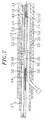
- FIG.3 A preferred means for attaching the catheter body 12 to the tip section 14 is illustrated in FIG.3.
- the proximal end of the tip section 14 comprises an outer circumferential notch 24 that receives the inner surface of the outer wall 22 of the catheter body 12.
- the tip section 14 and catheter body 12 are attached by glue or the like.
- a spacer 52 lies within the catheter body 12 between the distal end of the stiffening tube 20 and the proximal end of the tip section 14.
- the spacer 52 is preferably made of a material which is stiffer than the material of the tip section 14, e.g. polyurethane, but not as stiff as the material of the stiffening tube 20, e.g. polyimide.
- a spacer made of Teflon® is presently preferred.
- a preferred spacer 52 has a length of from about 6.4 mm to about 19 mm (about 0.25 inch to about 0.75 inch), more preferably about 12.7 mm (about 0.5 inch).
- the spacer 52 has an outer and inner diameter about the same as the outer and inner diameters of the stiffening tube 20.
- the spacer 52 provides a transition in flexibility at the junction of the catheter body 12 and catheter tip 14, which allows the junction of the catheter body 12 and tip section 14 to bend smoothly without folding or kinking.
- the spacer 52 is held in place by the stiffening tube 20.
- the stiffening tube 20 in turn, is held in place relative to the outer wall 22 by glue joints 23 and 25 at the proximal end of the catheter body 12.
- a force is applied to the proximal end of the stiffening tube 20 which causes the distal end of the stiffening tube 20 to firmly butt up against and compress the spacer 52.
- a first glue joint is made between the stiffening tube 20 and the outer wall 22 by a fast drying glue, e.g. Super Glue®.
- a second glue joint is formed between the proximal ends of the stiffening tube 20 and outer wall 22 using a slower drying but stronger glue, e.g.
- Extending through the single lumen 18 of the catheter body 12 are lead wires 40, an optic fiber 46, a sensor cable 74, and a compression coil 44 through which a puller wire 42 extends.
- a single lumen 18 catheter body is preferred over a multi-lumen body because it has been found that the single lumen 18 body permits better tip control when rotating the catheter 10.
- the single lumen 18 permits the lead wires 40, the optic fiber 46, the sensor cable 74, and the puller wire 42 surrounded by the compression coil 44 to float freely within the catheter body.
- the puller wire 42 is anchored at its proximal end to the control handle 16 and anchored at its distal end to the tip section 14.
- the puller wire 42 is made of any suitable metal, such as stainless steel or Nitinol, and is preferably coated with Teflon® or the like. The coating imparts lubricity to the puller wire 42.
- the puller wire 42 preferably has a diameter ranging from about 0.15 mm to about 0.25 mm (about 0.006 to about 0.010 inches).
- the compression coil 44 extends from the proximal end of the catheter body 12 to the proximal end of the tip section 14.
- the compression coil 44 is made of any suitable metal, preferably stainless steel.
- the compression coil 44 is tightly wound on itself to provide flexibility, i.e. bending, but to resist compression.
- the inner diameter of the compression coil 44 is preferably slightly larger than the diameter of the puller wire 42. For example, when the puller wire 42 has a diameter of about 0.18 mm (about 0.007 inches), the compression coil 44 preferably has an inner diameter of about 0.2 mm (about 0.008 inches).
- the Teflon® coating on the puller wire 42 allows it to slide freely within the compression coil 44.
- a flexible, non-conductive sheath 26 to prevent contact between the compression coil 44 and any of the lead wires 40, optic fiber 46 or sensor cable 74.
- a non-conductive sheath 26 made of polyimide tubing is presently preferred.
- the compression coil 44 is anchored at its proximal end to the proximal end of the stiffening tube 20 in the catheter body 12 by glue joint 29 and at its distal end to the tip section 14 at a location distal to the spacer 52 by glue joint 50.
- Both glue joints 29 and 50 preferably comprise polyurethane glue or the like.
- the glue may be applied by means of a syringe or the like through a hole made between the outer surface of the catheter body 12 and the single lumen 18. Such a hole may be formed, for example, by a needle or the like that punctures the wall of the catheter body 12 and the stiffening tube 20 which is heated sufficiently to form a permanent hole.
- the glue is then introduced through the hole to the outer surface of the compression coil 44 and wicks around the outer circumference to form a glue joint about the entire circumference of the compression coil 44.
- the puller wire 42 extends into the second lumen 32 of the tip section 14.
- the puller wire 42 is anchored to a tip electrode 36 or to the side of the catheter tip section 14.
- the turns of the compression coil are expanded longitudinally.
- Such expanded turns 47 are both bendable and compressible and preferably extend for a length of about 12.7 mm (about 0.5 inch).
- the puller wire 42 extends through the expanded turns 47 then into a plastic, preferably Teflon®, sheath 81, which prevents the puller wire 42 from cutting into the wall of the tip section 14 when the tip section 14 is deflected.
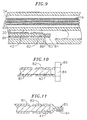
- the distal end of the puller wire 42 may be anchored to the tip electrode 36 by solder 43 or the like, as shown in FIG. 2b or to the side wall of the tip section 14. If attached to the side wall, an embodiment comprising an anchor 80 fixedly attached to the distal end of the puller wire 42 is preferred, as illustrated in FIGs. 9-11.
- the anchor is formed by a metal tube 82, e.g. a short segment of hypodermic stock, which is fixedly attached, e.g. by crimping, to the distal end of the puller wire 42.
- the tube 82 has a section which extends a short distance beyond the distal end of the puller wire 42.
- a cross-piece 84 made of a small section of stainless steel ribbon or the like is soldered or welded in a transverse arrangement to the distal end of the tube 82, which is flattened during the operation. This creates a T-bar anchor 80.
- a notch 86 is created in the side of the catheter tip section 14 resulting in an opening into the second lumen 32 carrying the puller wire 42.
- the anchor 80 lies within the notch 86. Because the length of the ribbon forming the cross-piece 84 is longer than the diameter of the opening into the second lumen 32, the anchor 80 cannot be pulled completely into the second lumen 32.
- the notch 86 is then sealed with polyurethane or the like to give a smooth outer surface.
- a tip electrode 36 At the distal end of the tip section 14 is a tip electrode 36.
- the tip electrode 36 has a diameter about the same as the outer diameter of the tubing 19.
- the tip electrode 36 is connected to the tubing 19 by means of a plastic housing 21, preferably made of polyetheretherketone (PEEK).
- PEEK polyetheretherketone
- the proximal end of the tip electrode 36 is notched circumferentially and fits inside the distal end of the plastic housing 21 and is bonded to the housing 21 by polyurethane glue or the like.
- the proximal end of the plastic housing 21 is bonded with polyurethane glue or the like to the distal end of the tubing 19 of the tip section 14.
- a ring electrode 38 mounted on the distal end of the plastic housing 21 is a ring electrode 38.
- the ring electrode 38 is slid over the plastic housing 21 and fixed in place by glue or the like. If desired, additional ring electrodes may be used and can be positioned over the plastic housing 21 or over the flexible tubing 19 of the tip section 14.
- the tip electrode 36 and ring electrode 38 are each connected to separate lead wires 40.
- the lead wires 40 extend through the third lumen 34 of tip section 14. the catheter body 12, and the control handle 16, and terminate at their proximal end in an input jack (not shown) that may be plugged into an appropriate monitor (not shown). If desired. the portion of the lead wires 40 extending through the catheter body 12, control handle 16 and proximal end of the tip section 14 may be enclosed or bundled within a protective tube or sheath.
- the lead wires 40 are attached to the tip electrode 36 and ring electrode 38 by any conventional technique. Connection of lead wire 40 to the tip electrode 36 is preferably accomplished by weld 43, as shown in FIG. 2b. Connection of a lead wire 40 to a ring electrode 38 is preferably accomplished by first making a small hole through the plastic housing 21. Such a hole can be created, for example, by inserting a needle through the plastic housing 21 and heating the needle sufficiently to form a permanent hole. A lead wire 40 is then drawn through the hole by using a microhook or the like. The ends of the lead wire 40 are then stripped of any coating and soldered or welded to the underside of the ring electrode 38, which is then slid into position over the hole and fixed in place with polyurethane glue or the like.
- a temperature sensing means is provided for the tip electrode 36 and, if desired, the ring electrode 38.
- Any conventional temperature sensing means e.g., a thermocouple or therraistor, may be used.
- a preferred temperature sensing means for the tip electrode 36 comprises a thermocouple formed by an enameled wire pair.
- One wire of the wire pair is a copper wire 41, e.g., a number 40 copper wire which acts not only as part of the thermocouple, but as the electrode lead.
- the other wire of the wire pair is a construction wire 45, e.g., a number 40 construction wire, which gives support and strength to the wire pair.
- the wires 41 and 45 of the wire pair are electrically isolated from each other except at their distal ends where they contact and are welded or soldered to the tip electrode 36. Because it is desirable to monitor the temperature of the tip electrode 36 at a site adjacent the distal end of the optic fiber 46, the thermocouple with a blind hole in the tip electrode 36 is fixed to the tip electrode 36 at the distal end of the blind hole as shown.
- An optic fiber 46 for transmitting laser energy to create channels in the heart tissue slidably extends through the control handle 16 and catheter body 12 and into the first lumen 30 of the tip section 14.
- channels refers to percutaneous myocardial channels that are formed in the heart tissue when the laser is fired. Preferred channels are approximately 1.0 millimeter in diameter and up to about 5.0 millimeters deep.
- the distal end of the optic fiber 46 extends through an optic fiber lumen in the tip electrode 36 and is fixed to the tip electrode 36 by glue or the like. The distal end of the optic fiber 46 is flush with the distal surface of the tip electrode.
- a connector (not shown) at the proximal end of the optic fiber 46 can be used to connect the proximal end of the optic fiber 46 to a laser (not shown). Any suitable laser can be used.
- a presently preferred laser is a Shaplan Ho: YAG 2040 Laser.
- the optic fiber 46 comprises a quartz core 48, a cladding made of doped silica or the like and a surrounding jacket 45.
- the jacket 45 can be of any suitable material, preferably aluminum, but materials such as such as nylon and polyimide may also be used.
- An aluminum jacket 45 is preferred as it tends to maximize the strength of the optic fiber 46 so that when the optic fiber is bent, e.g., when the catheter tip 14 is deflected, the quartz core does not break.
- the aluminum jacket 45 is stripped from the core 48. There are two principle reasons for this. The first is to prevent material from the aluminum jacket (or any other type of jacket) from breaking off into the heart chamber, particularly during laser transmission, which could lead to a stroke. The second is to electrically isolate the aluminum jacket 45 from the tip eiectrode 36. This is a safety measure to assure that a short circuit does not occur between the jacket 45 and tip electrode 36 that could deliver a potentially lethal burst of high voltage to the patient during laser transmission. A plastic, preferably polyimide, protective tube 47 is placed in surrounding relation to the portion of the optic fiber 46 covered by the jacket 45 that is situated within the tip electrode 36.
- the protective tube 47 prevents electrical contact between the jacket 45 and the tip electrode 36.
- the protective tube 47 extends beyond the distal end of the aluminum jacket 45 to help support the core 48.
- the protective tube 47 cannot extend too close to the distal tip of the optic fiber 46, however, because it would melt when the laser is fired.
- the protective tube 47 is fixed to the tip electrode 36 by glue or the like.
- An electromagnetic sensor 72 is contained within the distal end of the tip section 14.
- the electromagnetic sensor 72 is connected by means of electromagnetic sensor cable 74, which extends through the third lumen 34 of the tip section 14 through the catheter body 12 into the control handle 16.
- the electromagnetic sensor cable 74 comprises multiple wires encased within a plastic covered sheath.
- the wires of the sensor cable 74 are connected to a circuit board 64.
- the circuit board 64 amplifies the signal received from the electromagnetic sensor and transmits it to a computer in a form understandable by the computer.
- the circuit board contains an EPROM chip which shuts down the circuit board after the catheter has been used. This prevents the catheter, or at least the electromagnetic sensor, from being used twice.
- a suitable electromagnetic sensor is described, for example, in U.S. Patent No. 4,391,199.
- a preferred electromagnetic mapping sensor 72 is manufactured by Biosense Ltd. Israel and marketed under the trade designation NOGA.
- NOGA nuclear magnetic index
- To use the electromagnetic sensor 72 the patient is placed in a magnetic field generated, for example, by situating under the patient a pad containing coils for generating a magnetic field.
- a reference electromagnetic sensor is fixed relative to the patient, e.g., taped to the patient's back, and the DMR catheter containing a second electromagnetic sensor is advanced into the patient's heart.
- Each sensor comprises three small coils which in the magnetic field generate weak electrical signals indicative of their position in the magnetic field.
- Signals generated by both the fixed reference sensor and the second sensor in the heart are amplified and transmitted to a computer which analyzes the signals and then displays the signals on a monitor.
- a computer which analyzes the signals and then displays the signals on a monitor.
- the physician can visually map a heart chamber. This mapping is done by advancing the catheter tip into a heart chamber until contact is made with the heart wall. This position is recorded and saved. The catheter tip is then moved to another position in contact with the heart wall and again the position is recorded and saved.
- the electromagnetic mapping sensor 72 can be used alone or more preferably in combination with the tip electrode 36 and ring electrode 38. By combining the electromagnetic sensor 72 and electrodes 36 and 38, a physician can simultaneously map the contours or shape of the heart chamber, the electrical activity of the heart, and the extent of displacement of the catheter and hence identify the presence and location of the ischemic tissue. Specifically, the electromagnetic mapping sensor 72 is used to monitor the precise location of the tip electrode in the heart and the extent of catheter displacement. The tip electrode 36 and ring electrode 38 are used to monitor the strength of the electrical signals at that location. Healthy heart tissue is identified by strong electrical signals in combination with strong displacement. Dead or diseased heart tissue is identified by weak electrical signals in combination with dysfunctional displacement, i.e., displacement in a direction opposite that of healthy tissue.
- the combination of the electromagnetic mapping sensor 72 and tip and ring electrodes 36 and 38 is used as a diagnostic catheter to determine whether and where use of the laser is appropriate.
- the DMR catheter can be deflected so that the optic fiber is normal, i.e., at a right angle, to the ischemic tissue, and laser energy is fired through the optic fiber in coordination with the heart activity, e.g. during systole, to create a channel in the ischemic tissue, for example, as described in U.S. Patent Nos. 5,554,152, 5,389,096, and 5,380,316. This procedure is repeated to create multiple channels.
- a preferred mapping system includes a catheter comprising multiple electrodes and an electromagnetic sensor, such as the NOGA-STAR catheter marketed by Cordis Webster, Inc., and means for monitoring and displaying the signals received from the electrodes and electromagnetic sensor, such as the Biosense-NOGA system, also marketed by Cordis Webster, Inc.
- the electrode lead wires 40, optic fiber 46 and electromagnetic sensor cable 74 must be allowed some longitudinal movement within the catheter body so that they do not break when the tip section 14 is deflected.
- the tunnels are formed by transfer tubes 27, preferably made of short segments of polyimide tubing.
- transfer tubes 27 for the glue joint 50.
- Each transfer tube is approximately 60 mm long and has an outer diameter of about 0.53 mm (about .021 inch) and an inner diameter of about 0.48 mm (about .019 inch).
- Extending through one transfer tube 27 are the lead wires 40 and the electromagnetic sensor cable 74.
- Extending through the other transfer tube 27 is the optic fiber 46.
- An additional transfer tube 29 is located at the joint between the tip section 14 and the catheter body 12. Extending through this transfer tube is the optic fiber 46. This transfer tube 29 provides a tunnel through the glue joint formed when the tip section 14 is glued to the catheter body 12. It is understood that the number of transfer tubes may vary as desired.
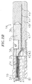
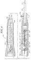
- the distal end of the control handle 16 comprises a piston 54 with a thumb control 56 for manipulating the puller wire 42.
- the proximal end of the catheter body 12 is connected to the piston 54 by means of a shrink sleeve 28.
- the optic fiber 46, puller wire 42, lead wires 40 and electromagnetic sensor cable 74 extend through the piston 54.
- the puller wire 42 is anchored to an anchor pin 36, located proximal to the piston 54.
- the lead wires 40 and electromagnetic sensor cable 74 extend though a first tunnel 58, located near the side of the control handle 16.
- the electromagnetic sensor cable 74 connects to the circuit board 64 in the proximal end of the control handle 16.
- Wires 80 connect the circuit board 64 to a computer and imaging monitor (not shown).
- the optic fiber 46 extends through a guide tube 66, preferably made of polyurethane, and is afforded longitudinal movement therein.
- the polyurethane guide tube 66 is anchored to the piston 54, preferably by glue at glue joint 53. This allows the optic fiber 46 longitudinal movement within the control handle 16 so that it does not break when the piston 54 is adjusted to manipulate the puller wire 42.
- the puller wire 42 is situated within a transfer tube 27, and the electromagnetic sensor cable 74 and lead wires 40 are situated within another transfer tube 27 to allow longitudinal movement of the wires and cable near the glue joint 53.
- the optic fiber 46 and guide tube 66 extend through a second tunnel 60 situated near the side of the control handle 16 opposite the anchor pin 36.
- a space 62 is provided between the proximal end of the piston 54 and the distal end of the second tunnel 60.
- the space 62 has a length of at least 12.7 mm (0.50 inch) and more preferably from about 15.2 mm to about 22.9 mm (about 0.60 inch to about 0.90 inch).
- the optic fiber 46 and the polyurethane guide tube 66 extend through a second larger plastic guide tube 68, preferably made of Teflon®, which affords the guide tube 66 and optic fiber 46 longitudinal slidable movement.
- the second guide tube 68 is anchored to the inside of the control handle 16 by glue or the like and extends proximally beyond the control handle 16.
- the second guide tube 68 protects the fiber 46 both from contact with the circuit board 64 and from any sharp bends as the guide tube 66 and optic fiber 46 emerge from the control handle 16.
- an infusion tube 76 for infusing fluids including drugs such as fibroblast growth factor (FGP), vascular endothelial growth factor (VEGP), thromboxane-A2 or protein kinase-C.
- FGP fibroblast growth factor
- VEGP vascular endothelial growth factor
- thromboxane-A2 or protein kinase-C drugs that initiate or promote angiogenesis.
- FGP and VEGP work directly to initiate the formation of new blood vessels.
- Thromboxane-A2 and protein kinase-C work indirectly to form new blood vessels. They are released by blood platelets during clot formation and have specific receptor sites which release FGF and VEGF.
- Drugs such as dexamethasone in various forms, e.g., dexamethasone sodium phosphate and dexamethasone acetate, can be delivered to sites to reduce inflammation associated with trauma and foreign body reaction which lead to the formation of fibrosis and collagen capsules which, in turn, close the created channels.
- the infusion tube 76 may even be used for collecting tissue or fluid samples.
- the infusion tube 76 may be made of any suitable material, and is preferably made of polyimide tubing.
- the catheter 10 having an infusion tube 76.
- the catheter 10 comprises a single lumen catheter body 12 as described above and a catheter tip section 14 comprising four lumens. To accommodate four lumens in the tip section, the diameter of the catheter may need to be increased slightly.
- the infusion tube 76 extends through the catheter body 12 and into the fourth lumen 77 of the tip section 14.
- the distal end of the infusion tube 76 extends into an opening or passage through the tip electrode 36 and is fixed, e.g., by glue, to the tip electrode 36.
- the passage in the tip electrode 36 may be straight or branched as desired.
- the infusion tube 76 can replace the optic fiber 46 in the first lumen 30 of the triple lumen tip section 14 in the embodiment described above.
- the proximal end of the infusion tube 76 extends out of a sealed opening in the side wall of the catheter body and terminates in a luer hub or the like.
- the infusion tube 76 may extend through the control handle and terminate in a luer hub or the like at a location proximal to the handle.
- fluids including drugs to promote revascularization, may be infused into the heart at the precise location of the revascularization procedure.
- a guide wire hole 78 is provided at the distal end of the tip section 14.
- the guide wire hole 78 extends from the side of the tip electrode 36 to the distal end of the tip electrode at an angle of about 30° to the longitudinal axis of the tip electrode.
- an introducing sheath is passed into the heart and then the guide wire is introduced into the heart from the introducing sheath.
- two or more puller wires are provided to enhance the ability to manipulate the tip section.
- a second puller wire and a surrounding second compression coil extend through the catheter body and into separate off-axis lumens in the tip section.
- the lumens of the tip section receiving the puller wires may be in adjacent quadrants.
- the first puller wire is preferably anchored proximal to the anchor location of the second puller wire.
- the second puller wire may be anchored to the tip electrode or may be anchored to the wall of the tip section adjacent the distal end of tip section.
- the distance between the distal end of the compression coils and the anchor sites of each puller wire in the tip section determines the curvature of the tip section 14 in the direction of the puller wires.
- an arrangement wherein the two puller wires are anchored at different distances from the distal ends of the compression coils allows a long reach curve in a first plane and a short reach curve in a plane 90° from the first, i.e., a first curve in one plane generally along the axis of the tip section before it is deflected and a second curve distal to the first curve in a plane transverse, and preferably normal to the first plane.
- the high torque characteristic of the catheter tip section 12 reduces the tendency for the deflection in one direction to deform the deflection in the other direction.
- the puller wires may extend into diametrically opposed off-axis lumens in the tip section.
- each of the puller wires may be anchored at the same location along the length of the tip section, in which case the curvatures of the tip section in opposing directions are the same and the tip section can be made to deflect in either direction without rotation of the catheter body.
- a particularly preferred catheter construction comprising multiple puller wires including control handle construction is disclosed in pending patent application entitled OmniDirectional Steerable Catheter, naming as inventor Wilton W. Webster, Jr. (attorney docket P19810EP claiming priority of USSN 08/924611). filed concurrently herewith.
- Such application describes a suitable control handle for manipulating two or more puller wires.
- the described control handle includes a central passage that may be expanded to accommodate the electrode lead wires, electromagnetic sensor cable, optic fiber and even infusion tube. Further, an extension of the handle may be provided to house the circuit board for the electromagnetic sensor, e.g. in the same manner as shown in FIG. 4 herein.
Description
- The present invention relates to steerable catheters which are particularly useful in direct myocardial revascularization procedures.
- Direct myocardial revascularization (DMR), also referred to as percutaneous myocardial revascularization, is a technique that allows physicians to treat patients who have sustained a myocardial infraction by burning channels in the myocardium that has been determined to be ischemic heart tissue. The channels, which are burned by a laser, allow for angiogenesis, i.e., the formation of blood vessels.
- Several myocardial revascularization procedures are known that require that the chest wall be opened to access the heart muscle with laser devices. The procedures are not very desirable, as they require major surgery that can result in severe complications. Aita et al., U.S. Patent No. 5,389,096, describes a procedure for performing myocardial revascularization percutaneously by inserting a guidable elongated flexible lasing apparatus, such as a catheter, into a patient's vasculature. The distal end of the catheter is guided to an area in the heart to be revascularized. The inner wall of the heart is then irradiated with laser energy to cause a channel to be formed from the endocardium into the myocardium.
- For obvious reasons, DMR catheters require the physician to have more control and information than other catheters having an optic fiber, such as ablation catheters. Aita et al. generally describes a DMR catheter. The present invention is directed to an improved DMR catheter which allows the physician to have greater control and obtain more information than the catheter described in Aita el al.
- A guidable catheter for mapping and laser treating is also disclosed in US-A-5462544. US-A-5462544 describes a mapping and lasing catheter including a manipulating handle for deflecting the distal end of the catheter, and an optic fibre for optical or visual control of the end. However, it provides no guidance as to how to protect the optic fibre within the manipulating handle, in which there can be moving parts that could damage the optic fibre.
- The present invention, therefore, provides a design of DMR catheter that additionally protects the optic fibre in the catheter.
- The present invention provides a steerable direct myocardial revascularization catheter as defined in claim 1 that can be used to treat ischemic heart tissue. The steerable DMR catheter comprises a catheter body or shaft, a tip section attached to the distal end of the catheter body and a control handle attached to the proximal end of the catheter body. A puller wire is anchored at its proximal end in the control handle and extends through a lumen in the catheter body and a lumen in the tip section and is anchored at or about the distal end of the tip section.
Manipulation of the control handle results in deflection of the tip section. An optic fiber suitable for transmission of laser energy extends through the control handle, catheter body and tip section, the distal end of the optic fiber being generally flush with the distal end surface of the tip section. The proximal end of the optic fiber extends proximally from the control handle to a suitable connector which connects the optic fiber to a source of laser energy. The optic fiber is used to transmit laser energy for creating channels, i.e. blind holes, in the heart tissue which induces revascularization. - In a preferred embodiment of the invention, the tip section of the DMR catheter comprises an electromagnetic sensor. The electromagnetic sensor is connected to a circuit board by means of a sensor cable which extends proximally through the tip section, catheter body, and control handle. The circuit board is preferably housed in the handle. Signals from the circuit board are transmitted through a cable to a computer and monitor. The electromagnetic sensor allows a physician to create a visual representation of the heart chamber and to view the location of the sensor, and therefore the catheter tip, within the chamber.
- In another preferred embodiment, the DMR catheter comprises a tip electrode and one or more ring electrodes spaced proximally from the tip electrode. Each electrode is connected by means of electrode lead wires which extend through the tip section, catheter body and control handle to an appropriate connector, and from there, to a suitable monitor. The tip and ring electrodes allow the electrical activity of the heart tissue to be mapped. In a particularly preferred embodiment of the invention, the DMR catheter comprises both an electromagnetic sensor within the tip section and a tip electrode and one or more ring electrodes. This combination allows a physician to map the electrical activity of the heart wall of a particular chamber, e.g., the left ventricle, by means of the tip and ring electrodes to determine ischemic areas and simultaneously to record the precise location of the tip section within the heart by means of the electromagnetic sensor to create a three-dimensional representation of the heart chamber which is displayed visually on a monitor. Once an ischemic area has been mapped, the tip section is moved to that area and deflected to allow the optic fiber to be generally normal to the heart wall, and then laser energy is transmitted onto the heart tissue for creating a channel within the heart tissue.
- In another aspect of the invention, the optic fiber comprises a protective jacket, preferably made out of aluminum. The optic fiber extends through the control handle and catheter body and into the tip section which carries a tip electrode. In the tip section, the optic fiber extends through an optic fiber lumen in the tip electrode, the distal end of the optic fiber being flush with the distal face of the tip electrode. The aluminum jacket is removed from the distal portion of the optic fiber which extends through the tip electrode. This removal avoids the possibility that particles of the aluminum jacket may break free into the heart, especially during laser transmission, which could result in a stroke. This removal also prevents the possibility of an electrical short between the aluminum jacket and the tip electrode, which could result in the patient receiving a lethally high voltage during laser transmission.
- In another aspect of the invention, there is provided a DMR catheter having an infusion tube which extends from the proximal end of the catheter body through a lumen in the catheter body and into the tip section. The distal end of the infusion tube is open at the distal end of the tip section at a position adjacent the optic fiber so that fluids, including drugs to induce angiogenesis, may be passed through the catheter to the heart tissue. In a preferred embodiment, the DMR catheter comprises an infusion tube and a tip electrode having an infusion passage adjacent the optic fiber lumen. The infusion tube is connected to, preferably inserted into, the infusion passage in the tip electrode so that fluids passing through the infusion tube will enter and pass through the infusion passage in the tip electrode and to the heart tissue. The proximal end of the infusion tube terminates in a luer hub or the like.
- In yet another aspect of the invention, the catheter body or shaft comprises a construction which exhibits improved torsional stability, resulting in improved tip control while minimizing wall thickness. The catheter body comprises a single central lumen and is formed by a tubular outer wall of polyurethane or nylon with a braided stainless steel mesh imbedded in the outer wall. The inner surface of the outer wall is lined with a stiffening tube, preferably made of polyimide or the like. The use of a polyimide stiffening tube provides improved torsional stability while at the same time minimizing the wall thickness of the catheter. This, in turn, maximizes the diameter of the central lumen. Such a construction is particularly useful in steerable DMR catheters in which an optic fiber, a puller wire, electrode leads, and an electromagnetic sensor cable all extend through the lumen of the catheter body, but is also useful in other steerable catheter constructions.
- A preferred construction of the DMR catheter also includes a tubular spacer, between the polyimide stiffening tube and the tip section. The spacer is made of a material less stiff than the material of the stiffening tube, e.g., polyimide, but more stiff than the material of the tip section, e.g., polyurethane. Teflon® is the presently preferred material of the spacer.
- In a preferred method for constructing the catheter, the stiffening tube is inserted into the tubular outer wall until the distal end of the stiffening tube butts against the tubular spacer. Force is applied to the proximal end of the stiffening tube which tube is then fixed in position, e.g., by glue, to the outer wall. The application of force on the proximal end of the stiffening tube assures that no gaps will form between the stiffening tube and tubular spacer or between the spacer and tip section as a result of repeated tip deflection.
- In a steerable catheter construction comprising a stiffening tube and spacer, a puller wire preferably extends through a non-compressible compression coil which is fixed at its proximal end to the proximal end of the catheter body by means of a glue joint and fixed at its distal end to the proximal end of the tip section at a location distal to the spacer by means of a second glue joint. This arrangement prevents compression of the spacer during tip deflection which, in turn, permits the use of a thin walled spacer.
- In yet another aspect to the invention, a control handle is provided which can be manipulated to deflect the tip section of the catheter. The control handle has a first member which is attached to the catheter body and a second member movable with respect to the first member, which is attached to the puller wire. In this arrangement, movement of the first member relative to the second member results in deflection of the tip. The handle comprises a guide tube through which the optic fiber extends. The guide tube is fixedly secured to the first or second member. Within this guide, the optic fiber is afforded lengthwise movement with respect to both the first and second members.
- These and other features and advantages of the present invention will be better understood by reference to the following detailed description when considered in conjunction with the accompanying drawings wherein:
- FIG. 1 is a side cross-sectional view of an embodiment of the catheter of the invention.
- FIG. 2a is a side cross-sectional view of the catheter tip section showing an embodiment having three lumens and showing the position of the electromagnetic mapping sensor and the optic fiber.
- FIG. 2b is a side cross-sectional view of the catheter tip section showing an embodiment having three lumens and showing the position of the electromagnetic mapping sensor and the puller wire.
- FIG. 3 is a side cross-sectional view of the catheter body, including the junction between the catheter body and the tip section.
- FIG. 4 is a side cross-sectional view of the catheter handle.
- FIG. 5 is a transverse cross-sectional view of the catheter tip section along line 5-5 showing an embodiment having three lumens.
- FIG. 6 is a transverse cross-sectional view of the catheter body along line 6-6.
- FIG. 7 is a side cross-sectional view of the catheter body showing an infusion tube.
- FIG. 8 is a transverse cross-sectional view of the catheter tip section showing an alternative embodiment having an infusion tube.
- FIG. 9 is a cross-sectional view of a portion of the catheter tip section showing a preferred means for anchoring the puller wire.
- FIG. 10 is a top cross-sectional view of a preferred puller wire anchor.
- FIG. 11 is a side cross-sectional view of a preferred puller wire anchor.
-
- In a particularly preferred embodiment of the ir.vention, there is provided a catheter for use in direct myocardial revascularization (DMR). As shown in FIGs. 1-4,
catheter 10 comprises anelongated catheter body 12 having proximal and distal ends, atip section 14 at the distal end of thecatheter body 12, and acontrol handle 16 at the proximal end of thecatheter body 12. - With reference to FIGs. 3 and 6, the
catheter body 12 comprises an elongated tubular construction having a single, central oraxial lumen 18. Thecatheter body 12 is flexible, i.e., bendable, but substantially non-compressible along its length. Thecatheter body 12 can be of any suitable construction and made of any suitable material. A presently preferred construction comprises anouter wall 22 made of a polyurethane or nylon. Theouter wall 22 comprises an imbedded braided mesh of stainless steel or the like to increase torsional stiffness of thecatheter body 12 so that, when the control handle 16 is rotated, the tip section of thecatheter 10 will rotate in a corresponding manner. - The outer diameter of the
catheter body 12 is not critical, but is preferably no more than about 2.6 mm (about 8 french). Likewise the thickness of theouter wall 22 is not critical. The inner surface of theouter wall 22 is lined with a stiffeningtube 20, which can be made of any suitable material, preferably polyimide. The stiffening tube, along with the braidedouter wall 22, provides improved torsional stability while at the same time minimizing the wall thickness of the catheter, thus maximizing the diameter of the single lumen. The outer diameter of the stiffeningtube 20 is about the same as or slightly smaller than the inner diameter of theouter wall 22. Polyimide tubing is presently preferred because it may be very thin walled while still providing very good stiffness. This maximizes the diameter of thecentral lumen 18 without sacrificing strength and stiffness. Polyimide material is typically not used for stiffening tubes because of its tendency to kink when bent. However, it has been found that, in combination with anouter wall 22 of polyurethane, nylon or other similar material, particularly having a stainless steel braided mesh, the tendency for thepolyimide stiffening tube 20 to kink when bent is essentially eliminated with respect to the applications for which the catheter is used. - A particularly preferred catheter has an
outer wall 22 with an outer diameter of about 2.3 mm (about 0.092 inch) and an inner diameter of about 1.6 mm (about 0.063 inch) and a polyimide stiffening tube having an outer diameter of about 1.56 mm (about 0.0615 inch) and an inner diameter of about 1.3 mm (about 0.052 inch). - As shown in FIGs. 2a and 2b, the
tip section 14 comprises a short section oftubing 19 having three lumens. Thetubing 19 is made of a suitable non-toxic material which is preferably more flexible than thecatheter body 12. A presently preferred material for thetubing 19 is braided polyurethane, i.e., polyurethane with an embedded mesh of braided stainless steel or the like. The outer diameter of thetip section 14, like that of thecatheter body 12, is preferably no greater than about 2.6 mm (about 8 french). The size of the lumens is not critical. In a particularly preferred embodiment, the tip section has an outer diameter of about 2.3 mm (about 7 french (.092 inch)) and thefirst lumen 30 andsecond lumen 32 are generally about the same size, having a diameter of about 0.55 mm (about 0.022 inch), with thethird lumen 34 having a slightly larger diameter of about 0.9 mm (about 0.036 inch). - A preferred means for attaching the
catheter body 12 to thetip section 14 is illustrated in FIG.3. The proximal end of thetip section 14 comprises an outercircumferential notch 24 that receives the inner surface of theouter wall 22 of thecatheter body 12. Thetip section 14 andcatheter body 12 are attached by glue or the like. In the arrangement shown, aspacer 52 lies within thecatheter body 12 between the distal end of the stiffeningtube 20 and the proximal end of thetip section 14. Thespacer 52 is preferably made of a material which is stiffer than the material of thetip section 14, e.g. polyurethane, but not as stiff as the material of the stiffeningtube 20, e.g. polyimide. A spacer made of Teflon® is presently preferred. Apreferred spacer 52 has a length of from about 6.4 mm to about 19 mm (about 0.25 inch to about 0.75 inch), more preferably about 12.7 mm (about 0.5 inch). Preferably thespacer 52 has an outer and inner diameter about the same as the outer and inner diameters of the stiffeningtube 20. Thespacer 52 provides a transition in flexibility at the junction of thecatheter body 12 andcatheter tip 14, which allows the junction of thecatheter body 12 andtip section 14 to bend smoothly without folding or kinking. - The
spacer 52 is held in place by the stiffeningtube 20. The stiffeningtube 20, in turn, is held in place relative to theouter wall 22 byglue joints catheter body 12. In a preferred construction of thecatheter body 12, a force is applied to the proximal end of the stiffeningtube 20 which causes the distal end of the stiffeningtube 20 to firmly butt up against and compress thespacer 52. While under compression, a first glue joint is made between the stiffeningtube 20 and theouter wall 22 by a fast drying glue, e.g. Super Glue®. Thereafter a second glue joint is formed between the proximal ends of the stiffeningtube 20 andouter wall 22 using a slower drying but stronger glue, e.g. polyurethane. Construction of thecatheter body 12 whereby the stiffeningtube 20 andspacer 58 are under compression has been found to be advantageous to prevent the formation of gaps between the stiffeningtube 20 andspacer 58 or betweenspacer 58 and thetip section 14 which might otherwise occur after repeated tip deflections. Such gaps are undesirable because they cause the catheter to crease or fold over, hindering the catheter's ability to roll. - Extending through the
single lumen 18 of thecatheter body 12 arelead wires 40, anoptic fiber 46, asensor cable 74, and acompression coil 44 through which apuller wire 42 extends. Asingle lumen 18 catheter body is preferred over a multi-lumen body because it has been found that thesingle lumen 18 body permits better tip control when rotating thecatheter 10. Thesingle lumen 18 permits thelead wires 40, theoptic fiber 46, thesensor cable 74, and thepuller wire 42 surrounded by thecompression coil 44 to float freely within the catheter body. If such wires and cables were restricted within multiple lumens, they tend to build up energy when thehandle 16 is rotated, resulting in thecatheter body 12 having a tendency to rotate back if, for example, the handle is released, or if bent around a curve, to flip over, either of which are undesirable performance characteristics. - The
puller wire 42 is anchored at its proximal end to the control handle 16 and anchored at its distal end to thetip section 14. Thepuller wire 42 is made of any suitable metal, such as stainless steel or Nitinol, and is preferably coated with Teflon® or the like. The coating imparts lubricity to thepuller wire 42. Thepuller wire 42 preferably has a diameter ranging from about 0.15 mm to about 0.25 mm (about 0.006 to about 0.010 inches). - The
compression coil 44 extends from the proximal end of thecatheter body 12 to the proximal end of thetip section 14. Thecompression coil 44 is made of any suitable metal, preferably stainless steel. Thecompression coil 44 is tightly wound on itself to provide flexibility, i.e. bending, but to resist compression. The inner diameter of thecompression coil 44 is preferably slightly larger than the diameter of thepuller wire 42. For example, when thepuller wire 42 has a diameter of about 0.18 mm (about 0.007 inches), thecompression coil 44 preferably has an inner diameter of about 0.2 mm (about 0.008 inches). The Teflon® coating on thepuller wire 42 allows it to slide freely within thecompression coil 44. Along its length, the outer surface of thecompression coil 44 is covered by a flexible,non-conductive sheath 26 to prevent contact between thecompression coil 44 and any of thelead wires 40,optic fiber 46 orsensor cable 74. Anon-conductive sheath 26 made of polyimide tubing is presently preferred. - The
compression coil 44 is anchored at its proximal end to the proximal end of the stiffeningtube 20 in thecatheter body 12 by glue joint 29 and at its distal end to thetip section 14 at a location distal to thespacer 52 by glue joint 50. Bothglue joints catheter body 12 and thesingle lumen 18. Such a hole may be formed, for example, by a needle or the like that punctures the wall of thecatheter body 12 and the stiffeningtube 20 which is heated sufficiently to form a permanent hole. The glue is then introduced through the hole to the outer surface of thecompression coil 44 and wicks around the outer circumference to form a glue joint about the entire circumference of thecompression coil 44. - The
puller wire 42 extends into thesecond lumen 32 of thetip section 14. Thepuller wire 42 is anchored to atip electrode 36 or to the side of thecatheter tip section 14. With reference to FIGs. 2b and 3, within thetip section 14, and distal to the glue joint 51, the turns of the compression coil are expanded longitudinally. Such expanded turns 47 are both bendable and compressible and preferably extend for a length of about 12.7 mm (about 0.5 inch). Thepuller wire 42 extends through the expanded turns 47 then into a plastic, preferably Teflon®,sheath 81, which prevents thepuller wire 42 from cutting into the wall of thetip section 14 when thetip section 14 is deflected. - The distal end of the
puller wire 42 may be anchored to thetip electrode 36 by solder 43 or the like, as shown in FIG. 2b or to the side wall of thetip section 14. If attached to the side wall, an embodiment comprising ananchor 80 fixedly attached to the distal end of thepuller wire 42 is preferred, as illustrated in FIGs. 9-11. In such an embodiment, the anchor is formed by ametal tube 82, e.g. a short segment of hypodermic stock, which is fixedly attached, e.g. by crimping, to the distal end of thepuller wire 42. Thetube 82 has a section which extends a short distance beyond the distal end of thepuller wire 42. Across-piece 84 made of a small section of stainless steel ribbon or the like is soldered or welded in a transverse arrangement to the distal end of thetube 82, which is flattened during the operation. This creates a T-bar anchor 80. Anotch 86 is created in the side of thecatheter tip section 14 resulting in an opening into thesecond lumen 32 carrying thepuller wire 42. Theanchor 80 lies within thenotch 86. Because the length of the ribbon forming thecross-piece 84 is longer than the diameter of the opening into thesecond lumen 32, theanchor 80 cannot be pulled completely into thesecond lumen 32. Thenotch 86 is then sealed with polyurethane or the like to give a smooth outer surface. - With reference to FIGs. 2a and 2b, at the distal end of the
tip section 14 is atip electrode 36. Preferably thetip electrode 36 has a diameter about the same as the outer diameter of thetubing 19. Thetip electrode 36 is connected to thetubing 19 by means of aplastic housing 21, preferably made of polyetheretherketone (PEEK). The proximal end of thetip electrode 36 is notched circumferentially and fits inside the distal end of theplastic housing 21 and is bonded to thehousing 21 by polyurethane glue or the like. The proximal end of theplastic housing 21 is bonded with polyurethane glue or the like to the distal end of thetubing 19 of thetip section 14. - Mounted on the distal end of the
plastic housing 21 is aring electrode 38. Thering electrode 38 is slid over theplastic housing 21 and fixed in place by glue or the like. If desired, additional ring electrodes may be used and can be positioned over theplastic housing 21 or over theflexible tubing 19 of thetip section 14. - The
tip electrode 36 andring electrode 38 are each connected to separatelead wires 40. Thelead wires 40 extend through thethird lumen 34 oftip section 14. thecatheter body 12, and the control handle 16, and terminate at their proximal end in an input jack (not shown) that may be plugged into an appropriate monitor (not shown). If desired. the portion of thelead wires 40 extending through thecatheter body 12, control handle 16 and proximal end of thetip section 14 may be enclosed or bundled within a protective tube or sheath. - The
lead wires 40 are attached to thetip electrode 36 andring electrode 38 by any conventional technique. Connection oflead wire 40 to thetip electrode 36 is preferably accomplished by weld 43, as shown in FIG. 2b. Connection of alead wire 40 to aring electrode 38 is preferably accomplished by first making a small hole through theplastic housing 21. Such a hole can be created, for example, by inserting a needle through theplastic housing 21 and heating the needle sufficiently to form a permanent hole. Alead wire 40 is then drawn through the hole by using a microhook or the like. The ends of thelead wire 40 are then stripped of any coating and soldered or welded to the underside of thering electrode 38, which is then slid into position over the hole and fixed in place with polyurethane glue or the like. - In a particularly preferred embodiment of the invention, a temperature sensing means is provided for the
tip electrode 36 and, if desired, thering electrode 38. Any conventional temperature sensing means, e.g., a thermocouple or therraistor, may be used. With reference to FIG. 2b, a preferred temperature sensing means for thetip electrode 36 comprises a thermocouple formed by an enameled wire pair. One wire of the wire pair is acopper wire 41, e.g., anumber 40 copper wire which acts not only as part of the thermocouple, but as the electrode lead. The other wire of the wire pair is aconstruction wire 45, e.g., anumber 40 construction wire, which gives support and strength to the wire pair. Thewires tip electrode 36. Because it is desirable to monitor the temperature of thetip electrode 36 at a site adjacent the distal end of theoptic fiber 46, the thermocouple with a blind hole in thetip electrode 36 is fixed to thetip electrode 36 at the distal end of the blind hole as shown. - An
optic fiber 46 for transmitting laser energy to create channels in the heart tissue slidably extends through the control handle 16 andcatheter body 12 and into thefirst lumen 30 of thetip section 14. As used herein, "channels" refers to percutaneous myocardial channels that are formed in the heart tissue when the laser is fired. Preferred channels are approximately 1.0 millimeter in diameter and up to about 5.0 millimeters deep. - The distal end of the
optic fiber 46 extends through an optic fiber lumen in thetip electrode 36 and is fixed to thetip electrode 36 by glue or the like. The distal end of theoptic fiber 46 is flush with the distal surface of the tip electrode. A connector (not shown) at the proximal end of theoptic fiber 46 can be used to connect the proximal end of theoptic fiber 46 to a laser (not shown). Any suitable laser can be used. A presently preferred laser is a Shaplan Ho: YAG 2040 Laser. - The
optic fiber 46 comprises aquartz core 48, a cladding made of doped silica or the like and a surroundingjacket 45. Thejacket 45 can be of any suitable material, preferably aluminum, but materials such as such as nylon and polyimide may also be used. Analuminum jacket 45 is preferred as it tends to maximize the strength of theoptic fiber 46 so that when the optic fiber is bent, e.g., when thecatheter tip 14 is deflected, the quartz core does not break. - At the distal end of the
optic fiber 46, thealuminum jacket 45 is stripped from thecore 48. There are two principle reasons for this. The first is to prevent material from the aluminum jacket (or any other type of jacket) from breaking off into the heart chamber, particularly during laser transmission, which could lead to a stroke. The second is to electrically isolate thealuminum jacket 45 from thetip eiectrode 36. This is a safety measure to assure that a short circuit does not occur between thejacket 45 andtip electrode 36 that could deliver a potentially lethal burst of high voltage to the patient during laser transmission. A plastic, preferably polyimide,protective tube 47 is placed in surrounding relation to the portion of theoptic fiber 46 covered by thejacket 45 that is situated within thetip electrode 36. Theprotective tube 47 prevents electrical contact between thejacket 45 and thetip electrode 36. Theprotective tube 47 extends beyond the distal end of thealuminum jacket 45 to help support thecore 48. Theprotective tube 47 cannot extend too close to the distal tip of theoptic fiber 46, however, because it would melt when the laser is fired. Theprotective tube 47 is fixed to thetip electrode 36 by glue or the like. - An
electromagnetic sensor 72 is contained within the distal end of thetip section 14. Theelectromagnetic sensor 72 is connected by means ofelectromagnetic sensor cable 74, which extends through thethird lumen 34 of thetip section 14 through thecatheter body 12 into the control handle 16. Theelectromagnetic sensor cable 74 comprises multiple wires encased within a plastic covered sheath. In the control handle 16, the wires of thesensor cable 74 are connected to acircuit board 64. Thecircuit board 64 amplifies the signal received from the electromagnetic sensor and transmits it to a computer in a form understandable by the computer. Also, because the catheter is designed for single use only, the circuit board contains an EPROM chip which shuts down the circuit board after the catheter has been used. This prevents the catheter, or at least the electromagnetic sensor, from being used twice. A suitable electromagnetic sensor is described, for example, in U.S. Patent No. 4,391,199. A preferredelectromagnetic mapping sensor 72 is manufactured by Biosense Ltd. Israel and marketed under the trade designation NOGA. To use theelectromagnetic sensor 72, the patient is placed in a magnetic field generated, for example, by situating under the patient a pad containing coils for generating a magnetic field. A reference electromagnetic sensor is fixed relative to the patient, e.g., taped to the patient's back, and the DMR catheter containing a second electromagnetic sensor is advanced into the patient's heart. Each sensor comprises three small coils which in the magnetic field generate weak electrical signals indicative of their position in the magnetic field. Signals generated by both the fixed reference sensor and the second sensor in the heart are amplified and transmitted to a computer which analyzes the signals and then displays the signals on a monitor. By this method, the precise location of the sensor in the catheter relative to the reference sensor can be ascertained and visually displayed. The sensor can also detect displacement of the catheter that is caused by contraction of the heart muscle. - Using this technology, the physician can visually map a heart chamber. This mapping is done by advancing the catheter tip into a heart chamber until contact is made with the heart wall. This position is recorded and saved. The catheter tip is then moved to another position in contact with the heart wall and again the position is recorded and saved.
- The
electromagnetic mapping sensor 72 can be used alone or more preferably in combination with thetip electrode 36 andring electrode 38. By combining theelectromagnetic sensor 72 andelectrodes electromagnetic mapping sensor 72 is used to monitor the precise location of the tip electrode in the heart and the extent of catheter displacement. Thetip electrode 36 andring electrode 38 are used to monitor the strength of the electrical signals at that location. Healthy heart tissue is identified by strong electrical signals in combination with strong displacement. Dead or diseased heart tissue is identified by weak electrical signals in combination with dysfunctional displacement, i.e., displacement in a direction opposite that of healthy tissue. Ischemic, or hibernating or stunned, heart tissue is identified by strong electrical signals in combination with impaired displacement. Hence, the combination of theelectromagnetic mapping sensor 72 and tip andring electrodes - It is understood that, while it is preferred to include both electrophysiology electrodes and an electromagnetic sensor in the catheter tip, it is not necessary to include both. For example, a DMR catheter having an electromagnetic sensor but no electrophysiology electrodes may be used in combination with a separate mapping catheter system. A preferred mapping system includes a catheter comprising multiple electrodes and an electromagnetic sensor, such as the NOGA-STAR catheter marketed by Cordis Webster, Inc., and means for monitoring and displaying the signals received from the electrodes and electromagnetic sensor, such as the Biosense-NOGA system, also marketed by Cordis Webster, Inc.
- The
electrode lead wires 40,optic fiber 46 andelectromagnetic sensor cable 74 must be allowed some longitudinal movement within the catheter body so that they do not break when thetip section 14 is deflected. To provide for such lengthwise movement, there are provided tunnels through the glue joint 50, which fixes the proximal end of thecompression coil 44 inside thecatheter body 12. The tunnels are formed bytransfer tubes 27, preferably made of short segments of polyimide tubing. In the embodiment shown in FIG. 3, there are twotransfer tubes 27 for theglue joint 50. Each transfer tube is approximately 60 mm long and has an outer diameter of about 0.53 mm (about .021 inch) and an inner diameter of about 0.48 mm (about .019 inch). Extending through onetransfer tube 27 are thelead wires 40 and theelectromagnetic sensor cable 74. Extending through theother transfer tube 27 is theoptic fiber 46. - An
additional transfer tube 29 is located at the joint between thetip section 14 and thecatheter body 12. Extending through this transfer tube is theoptic fiber 46. Thistransfer tube 29 provides a tunnel through the glue joint formed when thetip section 14 is glued to thecatheter body 12. It is understood that the number of transfer tubes may vary as desired. - Longitudinal movement of the
puller wire 42 relative to thecatheter body 12, which results in deflection of thetip section 12, is accomplished by suitable manipulation of the control handle 16. The distal end of the control handle 16 comprises apiston 54 with athumb control 56 for manipulating thepuller wire 42. The proximal end of thecatheter body 12 is connected to thepiston 54 by means of a shrink sleeve 28. - The
optic fiber 46,puller wire 42,lead wires 40 andelectromagnetic sensor cable 74 extend through thepiston 54. Thepuller wire 42 is anchored to ananchor pin 36, located proximal to thepiston 54. Thelead wires 40 andelectromagnetic sensor cable 74 extend though afirst tunnel 58, located near the side of the control handle 16. Theelectromagnetic sensor cable 74 connects to thecircuit board 64 in the proximal end of the control handle 16.Wires 80 connect thecircuit board 64 to a computer and imaging monitor (not shown). - The
optic fiber 46 extends through aguide tube 66, preferably made of polyurethane, and is afforded longitudinal movement therein. Thepolyurethane guide tube 66 is anchored to thepiston 54, preferably by glue at glue joint 53. This allows theoptic fiber 46 longitudinal movement within the control handle 16 so that it does not break when thepiston 54 is adjusted to manipulate thepuller wire 42. Within thepiston 54, thepuller wire 42 is situated within atransfer tube 27, and theelectromagnetic sensor cable 74 andlead wires 40 are situated within anothertransfer tube 27 to allow longitudinal movement of the wires and cable near theglue joint 53. - The
optic fiber 46 and guidetube 66 extend through asecond tunnel 60 situated near the side of the control handle 16 opposite theanchor pin 36. To avoid undesirable bending of theoptic fiber 46, aspace 62 is provided between the proximal end of thepiston 54 and the distal end of thesecond tunnel 60. Preferably thespace 62 has a length of at least 12.7 mm (0.50 inch) and more preferably from about 15.2 mm to about 22.9 mm (about 0.60 inch to about 0.90 inch). - In the proximal end of the control handle 16, the
optic fiber 46 and thepolyurethane guide tube 66 extend through a second largerplastic guide tube 68, preferably made of Teflon®, which affords theguide tube 66 andoptic fiber 46 longitudinal slidable movement. Thesecond guide tube 68 is anchored to the inside of the control handle 16 by glue or the like and extends proximally beyond the control handle 16. Thesecond guide tube 68 protects thefiber 46 both from contact with thecircuit board 64 and from any sharp bends as theguide tube 66 andoptic fiber 46 emerge from the control handle 16. - In another preferred catheter constructed in accordance with the present invention, there is provided an
infusion tube 76 for infusing fluids, including drugs such as fibroblast growth factor (FGP), vascular endothelial growth factor (VEGP), thromboxane-A2 or protein kinase-C. These are drugs that initiate or promote angiogenesis. FGP and VEGP work directly to initiate the formation of new blood vessels. Thromboxane-A2 and protein kinase-C work indirectly to form new blood vessels. They are released by blood platelets during clot formation and have specific receptor sites which release FGF and VEGF. - Other preferred drugs that may be infused incluce those which minimize the effect of foreign body reaction and extend the potency of the created channels. Drugs such as dexamethasone in various forms, e.g., dexamethasone sodium phosphate and dexamethasone acetate, can be delivered to sites to reduce inflammation associated with trauma and foreign body reaction which lead to the formation of fibrosis and collagen capsules which, in turn, close the created channels.
- It is apparent that other drugs may be infused as desired. Moreover, saline, or the like, may be infused for controlling the temperature of the tip electrode. The
infusion tube 76 may even be used for collecting tissue or fluid samples. Theinfusion tube 76 may be made of any suitable material, and is preferably made of polyimide tubing. - With reference to FIGs. 7 and 8, there is shown a
catheter 10 having aninfusion tube 76. Thecatheter 10 comprises a singlelumen catheter body 12 as described above and acatheter tip section 14 comprising four lumens. To accommodate four lumens in the tip section, the diameter of the catheter may need to be increased slightly. Theinfusion tube 76 extends through thecatheter body 12 and into thefourth lumen 77 of thetip section 14. The distal end of theinfusion tube 76 extends into an opening or passage through thetip electrode 36 and is fixed, e.g., by glue, to thetip electrode 36. The passage in thetip electrode 36 may be straight or branched as desired. Alternatively, theinfusion tube 76 can replace theoptic fiber 46 in thefirst lumen 30 of the triplelumen tip section 14 in the embodiment described above. - The proximal end of the
infusion tube 76 extends out of a sealed opening in the side wall of the catheter body and terminates in a luer hub or the like. Alternatively, theinfusion tube 76 may extend through the control handle and terminate in a luer hub or the like at a location proximal to the handle. In this arrangement, fluids, including drugs to promote revascularization, may be infused into the heart at the precise location of the revascularization procedure. - In another embodiment, as shown in FIG. 8, a
guide wire hole 78 is provided at the distal end of thetip section 14. Theguide wire hole 78 extends from the side of thetip electrode 36 to the distal end of the tip electrode at an angle of about 30° to the longitudinal axis of the tip electrode. Theguide wire hole 78 a.lows a guide wire (not shown) to be introduced into the heart and thecatheter 10 to be passed over the guide wire until it is in the proper location within the heart. Generally, to get the guide wire into the heart, an introducing sheath is passed into the heart and then the guide wire is introduced into the heart from the introducing sheath. - In another preferred embodiment constructed in accordance with the present invention, two or more puller wires are provided to enhance the ability to manipulate the tip section. In such an embodiment, a second puller wire and a surrounding second compression coil extend through the catheter body and into separate off-axis lumens in the tip section. The lumens of the tip section receiving the puller wires may be in adjacent quadrants. The first puller wire is preferably anchored proximal to the anchor location of the second puller wire. The second puller wire may be anchored to the tip electrode or may be anchored to the wall of the tip section adjacent the distal end of tip section.
- The distance between the distal end of the compression coils and the anchor sites of each puller wire in the tip section determines the curvature of the
tip section 14 in the direction of the puller wires. For example, an arrangement wherein the two puller wires are anchored at different distances from the distal ends of the compression coils allows a long reach curve in a first plane and a short reach curve in a plane 90° from the first, i.e., a first curve in one plane generally along the axis of the tip section before it is deflected and a second curve distal to the first curve in a plane transverse, and preferably normal to the first plane. The high torque characteristic of thecatheter tip section 12 reduces the tendency for the deflection in one direction to deform the deflection in the other direction. - As an alternative to the above described embodiment, the puller wires may extend into diametrically opposed off-axis lumens in the tip section. In such an embodiment, each of the puller wires may be anchored at the same location along the length of the tip section, in which case the curvatures of the tip section in opposing directions are the same and the tip section can be made to deflect in either direction without rotation of the catheter body.
- A particularly preferred catheter construction comprising multiple puller wires including control handle construction is disclosed in pending patent application entitled OmniDirectional Steerable Catheter, naming as inventor Wilton W. Webster, Jr. (attorney docket P19810EP claiming priority of USSN 08/924611).
filed concurrently herewith. Such application describes a suitable control handle for manipulating two or more puller wires. The described control handle includes a central passage that may be expanded to accommodate the electrode lead wires, electromagnetic sensor cable, optic fiber and even infusion tube. Further, an extension of the handle may be provided to house the circuit board for the electromagnetic sensor, e.g. in the same manner as shown in FIG. 4 herein. - The preceding description has been presented with reference to presently preferred embodiments of the invention. Workers skilled in the art and technology to which this invention pertains will appreciate that alterations and changes in the described structure may be practised without meaningfully departing from the scope of this invention as defined in the claims.
- Accordingly, the foregoing description should not be read as pertaining only to the precise structures described and illustrated in the accompanying drawings, but rather should be read consistent with and as support to the following claims which are to have their fullest and fair scope.
Claims (10)
- A steerable direct myocardial revascularization catheter (10) comprising:a catheter body (12) having an outer wall (22), proximal and distal ends and at least one lumen (18) extending therethrough;a tip section (14) comprising flexible tubing (19) having proximal and distal ends and at least one lumen (30, 32, 34) therethrough, the proximal end of the tip section (14) being fixedly attached to the distal end of the catheter body (12);a control handle (16) comprising:a first member (54) fixedly attached to the proximal end of the catheter body (12);a second member being movable relative to the first member (54); anda first guide tube (66) extending through the control handle (16) from the proximal end to the distal end of the control handle (16), said first guide tube (66) being fixedly attached (53) to one of the first or second members;an optic fiber (46) having a distal end and a proximal end, said optic fiber (46) extending through and afforded lengthwise movement through the first guide tube (66) in the control handle (16), a lumen (18) in the catheter body (12) and a lumen (30) in the tip section (14), said distal end of the optic fiber (46) being substantially flush with the distal end of the tip section (14); anda puller wire (42) extending from the control handle (16) through a lumen (18) in the catheter body (12) and into an off axis lumen (32) in the catheter tip section (14), the distal end of the puller wire (42) being anchored to the tip section (14) at a location (43) along the length of the tip section (14) and the proximal end of the puller wire (42) being anchored to the second member of the control handle (16); whereinmovement of the second member relative to the first member results in longitudinal movement of the puller wire (42) relative to the catheter body (12) thereby to deflect the tip section (14) in the direction of the off axis lumen (32) through which the puller wire (42) extends.
- A catheter (10) according to claim 1, wherein the first guide tube (66) is fixedly attached to the first member of the control handle (16).
- A catheter (10) according to claim 1, wherein the first guide tube (66) is fixedly attached to the second member of the control handle (16).
- A catheter (10) according to claim 2 further comprising a second guide tube (68) fixedly attached within the second member of the control handle (16), wherein the optic fiber (46) and first guide tube (66) extend through and are afforded lengthwise movement through the second guide tube (68).
- A catheter (10) according to claim 1, wherein the first member of the control handle (16) comprises a piston (54) having distal and proximal ends and thumb control (56).
- A catheter (10) according to claim 5, wherein the first guide tube (66) is fixedly attached (53) in the piston (54).
- A catheter (10) according to claim 1, wherein the second member of the control handle comprises an anchor pin (36), wherein the puller wire (42) is anchored to said anchor pin (36).
- A catheter (10) according to claim 7, wherein the first guide tube (66) extends through a tunnel (60) on the side of the control handle (16) opposite the anchor pin (36), said tunnel (60) having distal and proximal ends.
- A catheter (10) according to claim 1, further comprising an electromagnetic mapping sensor (72) in the distal portion of the tip section (14) for producing electrical signals indicative of the location of the electromagnetic mapping sensor (72).
- A catheter (10) according to claim 9, further comprising a sensor cable (74) electrically attached to the electromagnetic mapping sensor (72) and extending through a lumen (34) in the tip section (14), through a lumen (18) in the catheter body (12) and into the control handle (16), wherein the sensor cable (74) is electrically attached to a circuit board (64) situated within the control handle (16) for receiving electrical signals from the electromagnetic mapping sensor (72).
Applications Claiming Priority (2)
| Application Number | Priority Date | Filing Date | Title |
|---|---|---|---|
| US08/924,341 US6027473A (en) | 1997-09-05 | 1997-09-05 | Handle for steerable DMR catheter |
| US924341 | 1997-09-05 |
Publications (2)
| Publication Number | Publication Date |
|---|---|
| EP0900574A1 EP0900574A1 (en) | 1999-03-10 |
| EP0900574B1 true EP0900574B1 (en) | 2004-11-24 |
Family
ID=25450100
Family Applications (1)
| Application Number | Title | Priority Date | Filing Date |
|---|---|---|---|
| EP98307122A Expired - Lifetime EP0900574B1 (en) | 1997-09-05 | 1998-09-04 | Handle for steerable DMR catheter |
Country Status (4)
| Country | Link |
|---|---|
| US (1) | US6027473A (en) |
| EP (1) | EP0900574B1 (en) |
| JP (1) | JP4223103B2 (en) |
| DE (1) | DE69827717T2 (en) |
Families Citing this family (71)
| Publication number | Priority date | Publication date | Assignee | Title |
|---|---|---|---|---|
| US6071274A (en) | 1996-12-19 | 2000-06-06 | Ep Technologies, Inc. | Loop structures for supporting multiple electrode elements |
| US6690963B2 (en) | 1995-01-24 | 2004-02-10 | Biosense, Inc. | System for determining the location and orientation of an invasive medical instrument |
| CA2242356C (en) | 1996-01-08 | 2005-08-23 | Biosense, Inc. | Methods and apparatus for myocardial revascularization |
| US6443974B1 (en) * | 1996-07-28 | 2002-09-03 | Biosense, Inc. | Electromagnetic cardiac biostimulation |
| US6332880B1 (en) | 1996-12-19 | 2001-12-25 | Ep Technologies, Inc. | Loop structures for supporting multiple electrode elements |
| US6203525B1 (en) * | 1996-12-19 | 2001-03-20 | Ep Technologies, Inc. | Catheterdistal assembly with pull wires |
| US6048329A (en) | 1996-12-19 | 2000-04-11 | Ep Technologies, Inc. | Catheter distal assembly with pull wires |
| US6071279A (en) | 1996-12-19 | 2000-06-06 | Ep Technologies, Inc. | Branched structures for supporting multiple electrode elements |
| JP4236014B2 (en) | 1997-01-08 | 2009-03-11 | バイオセンス・ウェブスター・インコーポレイテッド | Monitoring myocardial vascular regeneration |
| US6123725A (en) * | 1997-07-11 | 2000-09-26 | A-Med Systems, Inc. | Single port cardiac support apparatus |
| EP0900547B1 (en) * | 1997-09-05 | 2007-05-30 | Biosense Webster, Inc. | Steerable catheter for detecting and revascularizing ischemic myocardial tissue |
| JPH11221229A (en) | 1997-09-24 | 1999-08-17 | Eclipse Surgical Technol Inc | Catheter |
| US6554794B1 (en) | 1997-09-24 | 2003-04-29 | Richard L. Mueller | Non-deforming deflectable multi-lumen catheter |
| US6063082A (en) | 1997-11-04 | 2000-05-16 | Scimed Life Systems, Inc. | Percutaneous myocardial revascularization basket delivery system and radiofrequency therapeutic device |
| US20030113303A1 (en) * | 1998-02-05 | 2003-06-19 | Yitzhack Schwartz | Homing of embryonic stem cells to a target zone in tissue using active therapeutics or substances |
| US20030129750A1 (en) * | 1998-02-05 | 2003-07-10 | Yitzhack Schwartz | Homing of donor cells to a target zone in tissue using active therapeutics or substances |
| DE69838526T2 (en) | 1998-02-05 | 2008-07-03 | Biosense Webster, Inc., Diamond Bar | Device for releasing a drug in the heart |
| US7749215B1 (en) * | 1998-02-05 | 2010-07-06 | Biosense, Inc. | Intracardiac cell delivery and cell transplantation |
| US6447504B1 (en) | 1998-07-02 | 2002-09-10 | Biosense, Inc. | System for treatment of heart tissue using viability map |
| US6196230B1 (en) * | 1998-09-10 | 2001-03-06 | Percardia, Inc. | Stent delivery system and method of use |
| US6261304B1 (en) | 1998-09-10 | 2001-07-17 | Percardia, Inc. | Delivery methods for left ventricular conduit |
| US6217528B1 (en) | 1999-02-11 | 2001-04-17 | Scimed Life Systems, Inc. | Loop structure having improved tissue contact capability |
| WO2001013812A1 (en) * | 1999-08-25 | 2001-03-01 | Cardiofocus, Inc. | Maneuverable optical fiber device for cardiac photoablation |
| US6645199B1 (en) * | 1999-11-22 | 2003-11-11 | Scimed Life Systems, Inc. | Loop structures for supporting diagnostic and therapeutic elements contact with body tissue and expandable push devices for use with same |
| US6529756B1 (en) | 1999-11-22 | 2003-03-04 | Scimed Life Systems, Inc. | Apparatus for mapping and coagulating soft tissue in or around body orifices |
| US6613046B1 (en) | 1999-11-22 | 2003-09-02 | Scimed Life Systems, Inc. | Loop structures for supporting diagnostic and therapeutic elements in contact with body tissue |
| US6542781B1 (en) | 1999-11-22 | 2003-04-01 | Scimed Life Systems, Inc. | Loop structures for supporting diagnostic and therapeutic elements in contact with body tissue |
| US6508802B1 (en) * | 2000-05-23 | 2003-01-21 | Cornell Research Foundation, Inc. | Remote sensing gene therapy delivery device and method of administering a therapeutic solution to a heart |
| US6477396B1 (en) | 2000-07-07 | 2002-11-05 | Biosense Webster, Inc. | Mapping and ablation catheter |
| US6926669B1 (en) | 2000-10-10 | 2005-08-09 | Medtronic, Inc. | Heart wall ablation/mapping catheter and method |
| US6530914B1 (en) * | 2000-10-24 | 2003-03-11 | Scimed Life Systems, Inc. | Deflectable tip guide in guide system |
| US6979312B2 (en) * | 2001-04-12 | 2005-12-27 | Biotran Corporation, Inc. | Steerable sheath catheters |
| US6652506B2 (en) | 2001-05-04 | 2003-11-25 | Cardiac Pacemakers, Inc. | Self-locking handle for steering a single or multiple-profile catheter |
| US6648875B2 (en) | 2001-05-04 | 2003-11-18 | Cardiac Pacemakers, Inc. | Means for maintaining tension on a steering tendon in a steerable catheter |
| US20030236493A1 (en) * | 2002-06-25 | 2003-12-25 | Medamicus, Inc. | Articulating handle for a deflectable catheter and method therefor |
| US7819866B2 (en) | 2003-01-21 | 2010-10-26 | St. Jude Medical, Atrial Fibrillation Division, Inc. | Ablation catheter and electrode |
| US7101362B2 (en) * | 2003-07-02 | 2006-09-05 | St. Jude Medical, Atrial Fibrillation Division, Inc. | Steerable and shapable catheter employing fluid force |
| US7235070B2 (en) * | 2003-07-02 | 2007-06-26 | St. Jude Medical, Atrial Fibrillation Division, Inc. | Ablation fluid manifold for ablation catheter |
| US7179256B2 (en) * | 2003-10-24 | 2007-02-20 | Biosense Webster, Inc. | Catheter with ablation needle and mapping assembly |
| US7717875B2 (en) * | 2004-07-20 | 2010-05-18 | St. Jude Medical, Atrial Fibrillation Division, Inc. | Steerable catheter with hydraulic or pneumatic actuator |
| US8858495B2 (en) | 2004-12-28 | 2014-10-14 | St. Jude Medical, Atrial Fibrillation Division, Inc. | Five degree of freedom ultrasound catheter and catheter control handle |
| US7691095B2 (en) | 2004-12-28 | 2010-04-06 | St. Jude Medical, Atrial Fibrillation Division, Inc. | Bi-directional steerable catheter control handle |
| US8583260B2 (en) | 2004-12-28 | 2013-11-12 | St. Jude Medical, Atrial Fibrillation Division, Inc. | Long travel steerable catheter actuator |
| US7591784B2 (en) | 2005-04-26 | 2009-09-22 | St. Jude Medical, Atrial Fibrillation Division, Inc. | Bi-directional handle for a catheter |
| US7819868B2 (en) * | 2005-06-21 | 2010-10-26 | St. Jude Medical, Atrial Fibrilation Division, Inc. | Ablation catheter with fluid distribution structures |
| US7465288B2 (en) * | 2005-06-28 | 2008-12-16 | St. Jude Medical, Atrial Fibrillation Division, Inc. | Actuation handle for a catheter |
| US8777929B2 (en) | 2005-06-28 | 2014-07-15 | St. Jude Medical, Atrial Fibrillation Division, Inc. | Auto lock for catheter handle |
| AU2006311701B2 (en) * | 2005-11-08 | 2012-08-30 | Custom Medical Applications, Inc. | Reinforced catheter with articulated distal tip |
| JP2009517608A (en) * | 2005-11-23 | 2009-04-30 | ネオガイド システムズ, インコーポレイテッド | Non-metallic multi-strand control cable for steerable devices |
| WO2007070943A1 (en) * | 2005-12-19 | 2007-06-28 | Techmin Pty Limited | Induction coil sensing |
| US9833595B2 (en) | 2005-12-30 | 2017-12-05 | Biosense Webster, Inc. | Dual-lever bi-directional handle |
| US20070270679A1 (en) * | 2006-05-17 | 2007-11-22 | Duy Nguyen | Deflectable variable radius catheters |
| US7774051B2 (en) | 2006-05-17 | 2010-08-10 | St. Jude Medical, Atrial Fibrillation Division, Inc. | System and method for mapping electrophysiology information onto complex geometry |
| US8992470B2 (en) | 2006-05-19 | 2015-03-31 | Boston Scientific Scimed, Inc. | Control mechanism for steerable medical device |
| US20080081990A1 (en) * | 2006-09-28 | 2008-04-03 | The Research Foundation Of State University Of New York | Apparatus, system, kit and method for heart mapping |
| US8444637B2 (en) * | 2006-12-29 | 2013-05-21 | St. Jude Medical, Atrial Filbrillation Division, Inc. | Steerable ablation device |
| US20090299352A1 (en) * | 2007-12-21 | 2009-12-03 | Boston Scientific Scimed, Inc. | Steerable laser-energy delivery device |
| US8137336B2 (en) * | 2008-06-27 | 2012-03-20 | Boston Scientific Scimed, Inc. | Steerable medical device |
| US7780648B2 (en) | 2007-12-28 | 2010-08-24 | Boston Scientific Scimed, Inc. | Controlling movement of distal portion of medical device |
| US8048024B2 (en) | 2008-03-17 | 2011-11-01 | Boston Scientific Scimed, Inc. | Steering mechanism |
| US8048025B2 (en) * | 2008-07-07 | 2011-11-01 | Boston Scientific Scimed, Inc. | Multi-plane motion control mechanism |
| US8834357B2 (en) * | 2008-11-12 | 2014-09-16 | Boston Scientific Scimed, Inc. | Steering mechanism |
| US8808345B2 (en) * | 2008-12-31 | 2014-08-19 | Medtronic Ardian Luxembourg S.A.R.L. | Handle assemblies for intravascular treatment devices and associated systems and methods |
| JP5507096B2 (en) * | 2009-03-05 | 2014-05-28 | 株式会社フジクラ | Manufacturing method of dental probe |
| US8906013B2 (en) | 2010-04-09 | 2014-12-09 | Endosense Sa | Control handle for a contact force ablation catheter |
| US9795765B2 (en) | 2010-04-09 | 2017-10-24 | St. Jude Medical International Holding S.À R.L. | Variable stiffness steering mechanism for catheters |
| JP5687534B2 (en) * | 2011-03-18 | 2015-03-18 | 株式会社リバーセイコー | Operation handle device for in-vivo diagnostic device |
| JP5787394B2 (en) * | 2011-03-25 | 2015-09-30 | 日本ライフライン株式会社 | Tip deflectable catheter |
| US9855404B2 (en) | 2013-05-03 | 2018-01-02 | St. Jude Medical International Holding S.À R.L. | Dual bend radii steering catheter |
| US10675443B2 (en) | 2016-03-07 | 2020-06-09 | St. Jude Medical, Cardiology Division, Inc. | Medical device including an actuator restraining assembly |
| EP3695798A1 (en) * | 2019-02-13 | 2020-08-19 | National University of Ireland Galway | An ablation probe |
Family Cites Families (47)
| Publication number | Priority date | Publication date | Assignee | Title |
|---|---|---|---|---|
| US34502A (en) * | 1862-02-25 | Improvement in bakers ovens | ||
| FR2463381B1 (en) | 1979-08-10 | 1985-10-25 | Morin Lionel | SAFETY AMMUNITION FOR SHOOTING OR FAIR SHOOTING |
| US4662368A (en) * | 1983-06-13 | 1987-05-05 | Trimedyne Laser Systems, Inc. | Localized heat applying medical device |
| US4913142A (en) * | 1985-03-22 | 1990-04-03 | Massachusetts Institute Of Technology | Catheter for laser angiosurgery |
| US4967745A (en) * | 1987-04-10 | 1990-11-06 | Massachusetts Institute Of Technology | Multi-fiber plug for a laser catheter |
| US4850351A (en) * | 1985-05-22 | 1989-07-25 | C. R. Bard, Inc. | Wire guided laser catheter |
| US4917084A (en) * | 1985-07-31 | 1990-04-17 | C. R. Bard, Inc. | Infrared laser catheter system |
| US4785815A (en) * | 1985-10-23 | 1988-11-22 | Cordis Corporation | Apparatus for locating and ablating cardiac conduction pathways |
| US4834093A (en) * | 1986-02-03 | 1989-05-30 | Littleford Phillip O | Dilation catheter and method |
| US4860743A (en) * | 1986-10-27 | 1989-08-29 | University Of Florida | Laser method and apparatus for the recanalization of vessels and the treatment of other cardiac conditions |
| US4753223A (en) * | 1986-11-07 | 1988-06-28 | Bremer Paul W | System for controlling shape and direction of a catheter, cannula, electrode, endoscope or similar article |
| US4790310A (en) * | 1987-02-04 | 1988-12-13 | Robert Ginsburg | Laser catheter having wide angle sweep |
| DE3718139C1 (en) * | 1987-05-29 | 1988-12-08 | Strahlen Umweltforsch Gmbh | Cardiac catheter |
| US4844062A (en) * | 1987-10-23 | 1989-07-04 | Spectranetics Corporation | Rotating fiberoptic laser catheter assembly with eccentric lumen |
| US4788975B1 (en) * | 1987-11-05 | 1999-03-02 | Trimedyne Inc | Control system and method for improved laser angioplasty |
| US5242437A (en) * | 1988-06-10 | 1993-09-07 | Trimedyne Laser Systems, Inc. | Medical device applying localized high intensity light and heat, particularly for destruction of the endometrium |
| US4890898A (en) * | 1988-08-18 | 1990-01-02 | Hgm Medical Laser Systems, Inc. | Composite microsize optical fiber-electric lead cable |
| US5203772A (en) * | 1989-01-09 | 1993-04-20 | Pilot Cardiovascular Systems, Inc. | Steerable medical device |
| US4998916A (en) * | 1989-01-09 | 1991-03-12 | Hammerslag Julius G | Steerable medical device |
| US4993412A (en) * | 1989-08-02 | 1991-02-19 | Eclipse Surgical Technologies, Inc. | Method and apparatus for removal of obstructive substance from body channels |
| US4997431A (en) * | 1989-08-30 | 1991-03-05 | Angeion Corporation | Catheter |
| US5188634A (en) * | 1990-07-13 | 1993-02-23 | Trimedyne, Inc. | Rotatable laser probe with beveled tip |
| US5111832A (en) * | 1990-07-24 | 1992-05-12 | Sanjeev Saksena | Processes for the control of tachyarrhythmias by in vivo laser ablation of human heart tissue |
| US5125926A (en) * | 1990-09-24 | 1992-06-30 | Laser Engineering, Inc. | Heart-synchronized pulsed laser system |
| US5125924A (en) * | 1990-09-24 | 1992-06-30 | Laser Engineering, Inc. | Heart-synchronized vacuum-assisted pulsed laser system and method |
| US5383923A (en) * | 1990-10-20 | 1995-01-24 | Webster Laboratories, Inc. | Steerable catheter having puller wire with shape memory |
| US5505725A (en) * | 1990-10-30 | 1996-04-09 | Cardiogenesis Corporation | Shapeable optical fiber apparatus |
| US5389096A (en) * | 1990-12-18 | 1995-02-14 | Advanced Cardiovascular Systems | System and method for percutaneous myocardial revascularization |
| US5380316A (en) * | 1990-12-18 | 1995-01-10 | Advanced Cardiovascular Systems, Inc. | Method for intra-operative myocardial device revascularization |
| NZ242509A (en) * | 1991-05-01 | 1996-03-26 | Univ Columbia | Myocardial revascularisation using laser |
| WO1993015676A1 (en) * | 1992-02-05 | 1993-08-19 | Angelase, Inc. | Laser catheter with movable integral fixation wire |
| US5281212A (en) * | 1992-02-18 | 1994-01-25 | Angeion Corporation | Laser catheter with monitor and dissolvable tip |
| JPH06511181A (en) * | 1992-03-18 | 1994-12-15 | ザ・スペクトラネティックス・コーポレーション | Fiber optic catheter with flexible tip |
| US5263952A (en) * | 1992-03-25 | 1993-11-23 | Spectranetics | Two-piece tip for fiber optic catheter |
| US5318525A (en) * | 1992-04-10 | 1994-06-07 | Medtronic Cardiorhythm | Steerable electrode catheter |
| WO1994002077A2 (en) * | 1992-07-15 | 1994-02-03 | Angelase, Inc. | Ablation catheter system |
| ATE182273T1 (en) * | 1992-08-18 | 1999-08-15 | Spectranetics Corp | GUIDE WIRE WITH FIBER OPTICS |
| US5549542A (en) * | 1992-11-17 | 1996-08-27 | Life Medical Technologies, Inc. | Deflectable endoscope |
| ES2102187T3 (en) * | 1992-11-18 | 1997-07-16 | Spectrascience Inc | DIAGNOSTIC DEVICE FOR IMAGE FORMATION. |
| US5368564A (en) * | 1992-12-23 | 1994-11-29 | Angeion Corporation | Steerable catheter |
| US5462544A (en) * | 1993-05-05 | 1995-10-31 | Energy Life System Corporation | Continuous heart tissue mapping and lasing catheter |
| US5431168A (en) * | 1993-08-23 | 1995-07-11 | Cordis-Webster, Inc. | Steerable open-lumen catheter |
| US5358479A (en) * | 1993-12-06 | 1994-10-25 | Electro-Catheter Corporation | Multiform twistable tip deflectable catheter |
| US5591159A (en) * | 1994-11-09 | 1997-01-07 | Taheri; Syde A. | Transcavitary myocardial perfusion apparatus |
| WO1996035469A1 (en) * | 1995-05-10 | 1996-11-14 | Cardiogenesis Corporation | System for treating or diagnosing heart tissue |
| US5656030A (en) * | 1995-05-22 | 1997-08-12 | Boston Scientific Corporation | Bidirectional steerable catheter with deflectable distal tip |
| DE69629593T2 (en) * | 1995-06-12 | 2004-03-25 | Cordis Webster, Inc., Baldwin Park | CATHETER WITH AN ELECTRIC GUIDE SENSOR |
-
1997
- 1997-09-05 US US08/924,341 patent/US6027473A/en not_active Expired - Lifetime
-
1998
- 1998-09-04 DE DE69827717T patent/DE69827717T2/en not_active Expired - Lifetime
- 1998-09-04 EP EP98307122A patent/EP0900574B1/en not_active Expired - Lifetime
- 1998-09-07 JP JP26900698A patent/JP4223103B2/en not_active Expired - Fee Related
Also Published As
| Publication number | Publication date |
|---|---|
| JPH11188107A (en) | 1999-07-13 |
| US6027473A (en) | 2000-02-22 |
| JP4223103B2 (en) | 2009-02-12 |
| DE69827717D1 (en) | 2004-12-30 |
| DE69827717T2 (en) | 2005-11-24 |
| EP0900574A1 (en) | 1999-03-10 |
Similar Documents
| Publication | Publication Date | Title |
|---|---|---|
| EP0900574B1 (en) | Handle for steerable DMR catheter | |
| EP0900548B1 (en) | Steerable dmr catheter with infusion tube | |
| US5964757A (en) | Steerable direct myocardial revascularization catheter | |
| US6210362B1 (en) | Steerable catheter for detecting and revascularing ischemic myocardial tissue | |
| US5897529A (en) | Steerable deflectable catheter having improved flexibility | |
| US6024739A (en) | Method for detecting and revascularizing ischemic myocardial tissue | |
| US6602242B1 (en) | Irrigated tip catheter | |
| EP0985423B1 (en) | Bi-directional control handle for steerable catheter | |
| US6183463B1 (en) | Bidirectional steerable cathether with bidirectional control handle | |
| EP0928600B1 (en) | Steerable catheter with electromagnetic sensor | |
| US7806872B2 (en) | Injection catheter with needle stop | |
| US8977344B2 (en) | Injection catheter with needle electrode | |
| EP0962191B1 (en) | Catheter for injecting therapeutic and diagnostic agents | |
| EP0904795A1 (en) | Thin-walled catheter with high torsional stiffness | |
| US20010009986A1 (en) | Steerable catheter for detecting and revascularizing ischemic myocardial tissue | |
| JP4566390B2 (en) | Infusion catheter |
Legal Events
| Date | Code | Title | Description |
|---|---|---|---|
| PUAI | Public reference made under article 153(3) epc to a published international application that has entered the european phase |
Free format text: ORIGINAL CODE: 0009012 |
|
| AK | Designated contracting states |
Kind code of ref document: A1 Designated state(s): BE DE FR GB IE IT NL |
|
| AX | Request for extension of the european patent |
Free format text: AL;LT;LV;MK;RO;SI |
|
| 17P | Request for examination filed |
Effective date: 19990819 |
|
| AKX | Designation fees paid |
Free format text: BE DE FR GB IE IT NL |
|
| 17Q | First examination report despatched |
Effective date: 20020920 |
|
| GRAP | Despatch of communication of intention to grant a patent |
Free format text: ORIGINAL CODE: EPIDOSNIGR1 |
|
| GRAS | Grant fee paid |
Free format text: ORIGINAL CODE: EPIDOSNIGR3 |
|
| GRAA | (expected) grant |
Free format text: ORIGINAL CODE: 0009210 |
|
| RAP1 | Party data changed (applicant data changed or rights of an application transferred) |
Owner name: BIOSENSE WEBSTER, INC. |
|
| AK | Designated contracting states |
Kind code of ref document: B1 Designated state(s): BE DE FR GB IE IT NL |
|
| PG25 | Lapsed in a contracting state [announced via postgrant information from national office to epo] |
Ref country code: IT Free format text: LAPSE BECAUSE OF FAILURE TO SUBMIT A TRANSLATION OF THE DESCRIPTION OR TO PAY THE FEE WITHIN THE PRESCRIBED TIME-LIMIT;WARNING: LAPSES OF ITALIAN PATENTS WITH EFFECTIVE DATE BEFORE 2007 MAY HAVE OCCURRED AT ANY TIME BEFORE 2007. THE CORRECT EFFECTIVE DATE MAY BE DIFFERENT FROM THE ONE RECORDED. Effective date: 20041124 Ref country code: BE Free format text: LAPSE BECAUSE OF FAILURE TO SUBMIT A TRANSLATION OF THE DESCRIPTION OR TO PAY THE FEE WITHIN THE PRESCRIBED TIME-LIMIT Effective date: 20041124 |
|
| REG | Reference to a national code |
Ref country code: GB Ref legal event code: FG4D |
|
| RIC1 | Information provided on ipc code assigned before grant |
Ipc: 7A 61M 25/01 A |
|
| REF | Corresponds to: |
Ref document number: 69827717 Country of ref document: DE Date of ref document: 20041230 Kind code of ref document: P |
|
| REG | Reference to a national code |
Ref country code: IE Ref legal event code: FG4D |
|
| PG25 | Lapsed in a contracting state [announced via postgrant information from national office to epo] |
Ref country code: IE Free format text: LAPSE BECAUSE OF NON-PAYMENT OF DUE FEES Effective date: 20050905 |
|
| PLBE | No opposition filed within time limit |
Free format text: ORIGINAL CODE: 0009261 |
|
| STAA | Information on the status of an ep patent application or granted ep patent |
Free format text: STATUS: NO OPPOSITION FILED WITHIN TIME LIMIT |
|
| ET | Fr: translation filed | ||
| 26N | No opposition filed |
Effective date: 20050825 |
|
| REG | Reference to a national code |
Ref country code: IE Ref legal event code: MM4A |
|
| PGFP | Annual fee paid to national office [announced via postgrant information from national office to epo] |
Ref country code: GB Payment date: 20110831 Year of fee payment: 14 Ref country code: DE Payment date: 20110831 Year of fee payment: 14 Ref country code: FR Payment date: 20110922 Year of fee payment: 14 |
|
| PGFP | Annual fee paid to national office [announced via postgrant information from national office to epo] |
Ref country code: NL Payment date: 20110922 Year of fee payment: 14 |
|
| REG | Reference to a national code |
Ref country code: NL Ref legal event code: V1 Effective date: 20130401 |
|
| GBPC | Gb: european patent ceased through non-payment of renewal fee |
Effective date: 20120904 |
|
| REG | Reference to a national code |
Ref country code: FR Ref legal event code: ST Effective date: 20130531 |
|
| PG25 | Lapsed in a contracting state [announced via postgrant information from national office to epo] |
Ref country code: DE Free format text: LAPSE BECAUSE OF NON-PAYMENT OF DUE FEES Effective date: 20130403 Ref country code: GB Free format text: LAPSE BECAUSE OF NON-PAYMENT OF DUE FEES Effective date: 20120904 |
|
| PG25 | Lapsed in a contracting state [announced via postgrant information from national office to epo] |
Ref country code: NL Free format text: LAPSE BECAUSE OF NON-PAYMENT OF DUE FEES Effective date: 20130401 Ref country code: FR Free format text: LAPSE BECAUSE OF NON-PAYMENT OF DUE FEES Effective date: 20121001 |
|
| REG | Reference to a national code |
Ref country code: DE Ref legal event code: R119 Ref document number: 69827717 Country of ref document: DE Effective date: 20130403 |