EP0900591A1 - Electric discharge reactor and use thereof - Google Patents
Electric discharge reactor and use thereof Download PDFInfo
- Publication number
- EP0900591A1 EP0900591A1 EP98810849A EP98810849A EP0900591A1 EP 0900591 A1 EP0900591 A1 EP 0900591A1 EP 98810849 A EP98810849 A EP 98810849A EP 98810849 A EP98810849 A EP 98810849A EP 0900591 A1 EP0900591 A1 EP 0900591A1
- Authority
- EP
- European Patent Office
- Prior art keywords
- discharge reactor
- reactor according
- discharge
- block
- gap
- Prior art date
- Legal status (The legal status is an assumption and is not a legal conclusion. Google has not performed a legal analysis and makes no representation as to the accuracy of the status listed.)
- Granted
Links
Images

Classifications
-
- B—PERFORMING OPERATIONS; TRANSPORTING
- B01—PHYSICAL OR CHEMICAL PROCESSES OR APPARATUS IN GENERAL
- B01J—CHEMICAL OR PHYSICAL PROCESSES, e.g. CATALYSIS OR COLLOID CHEMISTRY; THEIR RELEVANT APPARATUS
- B01J19/00—Chemical, physical or physico-chemical processes in general; Their relevant apparatus
- B01J19/08—Processes employing the direct application of electric or wave energy, or particle radiation; Apparatus therefor
- B01J19/087—Processes employing the direct application of electric or wave energy, or particle radiation; Apparatus therefor employing electric or magnetic energy
- B01J19/088—Processes employing the direct application of electric or wave energy, or particle radiation; Apparatus therefor employing electric or magnetic energy giving rise to electric discharges
-
- C—CHEMISTRY; METALLURGY
- C01—INORGANIC CHEMISTRY
- C01B—NON-METALLIC ELEMENTS; COMPOUNDS THEREOF; METALLOIDS OR COMPOUNDS THEREOF NOT COVERED BY SUBCLASS C01C
- C01B13/00—Oxygen; Ozone; Oxides or hydroxides in general
- C01B13/10—Preparation of ozone
- C01B13/11—Preparation of ozone by electric discharge
-
- C—CHEMISTRY; METALLURGY
- C01—INORGANIC CHEMISTRY
- C01B—NON-METALLIC ELEMENTS; COMPOUNDS THEREOF; METALLOIDS OR COMPOUNDS THEREOF NOT COVERED BY SUBCLASS C01C
- C01B3/00—Hydrogen; Gaseous mixtures containing hydrogen; Separation of hydrogen from mixtures containing it; Purification of hydrogen
- C01B3/02—Production of hydrogen or of gaseous mixtures containing a substantial proportion of hydrogen
- C01B3/32—Production of hydrogen or of gaseous mixtures containing a substantial proportion of hydrogen by reaction of gaseous or liquid organic compounds with gasifying agents, e.g. water, carbon dioxide, air
- C01B3/34—Production of hydrogen or of gaseous mixtures containing a substantial proportion of hydrogen by reaction of gaseous or liquid organic compounds with gasifying agents, e.g. water, carbon dioxide, air by reaction of hydrocarbons with gasifying agents
- C01B3/342—Production of hydrogen or of gaseous mixtures containing a substantial proportion of hydrogen by reaction of gaseous or liquid organic compounds with gasifying agents, e.g. water, carbon dioxide, air by reaction of hydrocarbons with gasifying agents with the aid of electrical means, electromagnetic or mechanical vibrations, or particle radiations
-
- C—CHEMISTRY; METALLURGY
- C01—INORGANIC CHEMISTRY
- C01B—NON-METALLIC ELEMENTS; COMPOUNDS THEREOF; METALLOIDS OR COMPOUNDS THEREOF NOT COVERED BY SUBCLASS C01C
- C01B3/00—Hydrogen; Gaseous mixtures containing hydrogen; Separation of hydrogen from mixtures containing it; Purification of hydrogen
- C01B3/02—Production of hydrogen or of gaseous mixtures containing a substantial proportion of hydrogen
- C01B3/32—Production of hydrogen or of gaseous mixtures containing a substantial proportion of hydrogen by reaction of gaseous or liquid organic compounds with gasifying agents, e.g. water, carbon dioxide, air
- C01B3/34—Production of hydrogen or of gaseous mixtures containing a substantial proportion of hydrogen by reaction of gaseous or liquid organic compounds with gasifying agents, e.g. water, carbon dioxide, air by reaction of hydrocarbons with gasifying agents
- C01B3/38—Production of hydrogen or of gaseous mixtures containing a substantial proportion of hydrogen by reaction of gaseous or liquid organic compounds with gasifying agents, e.g. water, carbon dioxide, air by reaction of hydrocarbons with gasifying agents using catalysts
-
- C—CHEMISTRY; METALLURGY
- C07—ORGANIC CHEMISTRY
- C07C—ACYCLIC OR CARBOCYCLIC COMPOUNDS
- C07C29/00—Preparation of compounds having hydroxy or O-metal groups bound to a carbon atom not belonging to a six-membered aromatic ring
- C07C29/15—Preparation of compounds having hydroxy or O-metal groups bound to a carbon atom not belonging to a six-membered aromatic ring by reduction of oxides of carbon exclusively
- C07C29/151—Preparation of compounds having hydroxy or O-metal groups bound to a carbon atom not belonging to a six-membered aromatic ring by reduction of oxides of carbon exclusively with hydrogen or hydrogen-containing gases
- C07C29/152—Preparation of compounds having hydroxy or O-metal groups bound to a carbon atom not belonging to a six-membered aromatic ring by reduction of oxides of carbon exclusively with hydrogen or hydrogen-containing gases characterised by the reactor used
-
- C—CHEMISTRY; METALLURGY
- C07—ORGANIC CHEMISTRY
- C07C—ACYCLIC OR CARBOCYCLIC COMPOUNDS
- C07C29/00—Preparation of compounds having hydroxy or O-metal groups bound to a carbon atom not belonging to a six-membered aromatic ring
- C07C29/15—Preparation of compounds having hydroxy or O-metal groups bound to a carbon atom not belonging to a six-membered aromatic ring by reduction of oxides of carbon exclusively
- C07C29/151—Preparation of compounds having hydroxy or O-metal groups bound to a carbon atom not belonging to a six-membered aromatic ring by reduction of oxides of carbon exclusively with hydrogen or hydrogen-containing gases
- C07C29/153—Preparation of compounds having hydroxy or O-metal groups bound to a carbon atom not belonging to a six-membered aromatic ring by reduction of oxides of carbon exclusively with hydrogen or hydrogen-containing gases characterised by the catalyst used
- C07C29/154—Preparation of compounds having hydroxy or O-metal groups bound to a carbon atom not belonging to a six-membered aromatic ring by reduction of oxides of carbon exclusively with hydrogen or hydrogen-containing gases characterised by the catalyst used containing copper, silver, gold, or compounds thereof
-
- H—ELECTRICITY
- H05—ELECTRIC TECHNIQUES NOT OTHERWISE PROVIDED FOR
- H05H—PLASMA TECHNIQUE; PRODUCTION OF ACCELERATED ELECTRICALLY-CHARGED PARTICLES OR OF NEUTRONS; PRODUCTION OR ACCELERATION OF NEUTRAL MOLECULAR OR ATOMIC BEAMS
- H05H1/00—Generating plasma; Handling plasma
- H05H1/24—Generating plasma
- H05H1/2406—Generating plasma using dielectric barrier discharges, i.e. with a dielectric interposed between the electrodes
-
- B—PERFORMING OPERATIONS; TRANSPORTING
- B01—PHYSICAL OR CHEMICAL PROCESSES OR APPARATUS IN GENERAL
- B01J—CHEMICAL OR PHYSICAL PROCESSES, e.g. CATALYSIS OR COLLOID CHEMISTRY; THEIR RELEVANT APPARATUS
- B01J2219/00—Chemical, physical or physico-chemical processes in general; Their relevant apparatus
- B01J2219/08—Processes employing the direct application of electric or wave energy, or particle radiation; Apparatus therefor
- B01J2219/0803—Processes employing the direct application of electric or wave energy, or particle radiation; Apparatus therefor employing electric or magnetic energy
- B01J2219/0805—Processes employing the direct application of electric or wave energy, or particle radiation; Apparatus therefor employing electric or magnetic energy giving rise to electric discharges
- B01J2219/0807—Processes employing the direct application of electric or wave energy, or particle radiation; Apparatus therefor employing electric or magnetic energy giving rise to electric discharges involving electrodes
- B01J2219/0809—Processes employing the direct application of electric or wave energy, or particle radiation; Apparatus therefor employing electric or magnetic energy giving rise to electric discharges involving electrodes employing two or more electrodes
-
- B—PERFORMING OPERATIONS; TRANSPORTING
- B01—PHYSICAL OR CHEMICAL PROCESSES OR APPARATUS IN GENERAL
- B01J—CHEMICAL OR PHYSICAL PROCESSES, e.g. CATALYSIS OR COLLOID CHEMISTRY; THEIR RELEVANT APPARATUS
- B01J2219/00—Chemical, physical or physico-chemical processes in general; Their relevant apparatus
- B01J2219/08—Processes employing the direct application of electric or wave energy, or particle radiation; Apparatus therefor
- B01J2219/0873—Materials to be treated
- B01J2219/0881—Two or more materials
- B01J2219/0883—Gas-gas
-
- C—CHEMISTRY; METALLURGY
- C01—INORGANIC CHEMISTRY
- C01B—NON-METALLIC ELEMENTS; COMPOUNDS THEREOF; METALLOIDS OR COMPOUNDS THEREOF NOT COVERED BY SUBCLASS C01C
- C01B2201/00—Preparation of ozone by electrical discharge
- C01B2201/30—Dielectrics used in the electrical dischargers
- C01B2201/32—Constructional details of the dielectrics
-
- C—CHEMISTRY; METALLURGY
- C01—INORGANIC CHEMISTRY
- C01B—NON-METALLIC ELEMENTS; COMPOUNDS THEREOF; METALLOIDS OR COMPOUNDS THEREOF NOT COVERED BY SUBCLASS C01C
- C01B2201/00—Preparation of ozone by electrical discharge
- C01B2201/30—Dielectrics used in the electrical dischargers
- C01B2201/34—Composition of the dielectrics
-
- C—CHEMISTRY; METALLURGY
- C01—INORGANIC CHEMISTRY
- C01B—NON-METALLIC ELEMENTS; COMPOUNDS THEREOF; METALLOIDS OR COMPOUNDS THEREOF NOT COVERED BY SUBCLASS C01C
- C01B2203/00—Integrated processes for the production of hydrogen or synthesis gas
- C01B2203/02—Processes for making hydrogen or synthesis gas
- C01B2203/0205—Processes for making hydrogen or synthesis gas containing a reforming step
- C01B2203/0227—Processes for making hydrogen or synthesis gas containing a reforming step containing a catalytic reforming step
- C01B2203/0238—Processes for making hydrogen or synthesis gas containing a reforming step containing a catalytic reforming step the reforming step being a carbon dioxide reforming step
-
- C—CHEMISTRY; METALLURGY
- C01—INORGANIC CHEMISTRY
- C01B—NON-METALLIC ELEMENTS; COMPOUNDS THEREOF; METALLOIDS OR COMPOUNDS THEREOF NOT COVERED BY SUBCLASS C01C
- C01B2203/00—Integrated processes for the production of hydrogen or synthesis gas
- C01B2203/08—Methods of heating or cooling
- C01B2203/0805—Methods of heating the process for making hydrogen or synthesis gas
- C01B2203/0861—Methods of heating the process for making hydrogen or synthesis gas by plasma
-
- C—CHEMISTRY; METALLURGY
- C01—INORGANIC CHEMISTRY
- C01B—NON-METALLIC ELEMENTS; COMPOUNDS THEREOF; METALLOIDS OR COMPOUNDS THEREOF NOT COVERED BY SUBCLASS C01C
- C01B2203/00—Integrated processes for the production of hydrogen or synthesis gas
- C01B2203/10—Catalysts for performing the hydrogen forming reactions
- C01B2203/1041—Composition of the catalyst
- C01B2203/1047—Group VIII metal catalysts
- C01B2203/1052—Nickel or cobalt catalysts
-
- C—CHEMISTRY; METALLURGY
- C01—INORGANIC CHEMISTRY
- C01B—NON-METALLIC ELEMENTS; COMPOUNDS THEREOF; METALLOIDS OR COMPOUNDS THEREOF NOT COVERED BY SUBCLASS C01C
- C01B2203/00—Integrated processes for the production of hydrogen or synthesis gas
- C01B2203/10—Catalysts for performing the hydrogen forming reactions
- C01B2203/1041—Composition of the catalyst
- C01B2203/1076—Copper or zinc-based catalysts
-
- C—CHEMISTRY; METALLURGY
- C01—INORGANIC CHEMISTRY
- C01B—NON-METALLIC ELEMENTS; COMPOUNDS THEREOF; METALLOIDS OR COMPOUNDS THEREOF NOT COVERED BY SUBCLASS C01C
- C01B2203/00—Integrated processes for the production of hydrogen or synthesis gas
- C01B2203/12—Feeding the process for making hydrogen or synthesis gas
- C01B2203/1205—Composition of the feed
- C01B2203/1211—Organic compounds or organic mixtures used in the process for making hydrogen or synthesis gas
- C01B2203/1235—Hydrocarbons
- C01B2203/1241—Natural gas or methane
-
- Y—GENERAL TAGGING OF NEW TECHNOLOGICAL DEVELOPMENTS; GENERAL TAGGING OF CROSS-SECTIONAL TECHNOLOGIES SPANNING OVER SEVERAL SECTIONS OF THE IPC; TECHNICAL SUBJECTS COVERED BY FORMER USPC CROSS-REFERENCE ART COLLECTIONS [XRACs] AND DIGESTS
- Y02—TECHNOLOGIES OR APPLICATIONS FOR MITIGATION OR ADAPTATION AGAINST CLIMATE CHANGE
- Y02P—CLIMATE CHANGE MITIGATION TECHNOLOGIES IN THE PRODUCTION OR PROCESSING OF GOODS
- Y02P20/00—Technologies relating to chemical industry
- Y02P20/141—Feedstock
-
- Y—GENERAL TAGGING OF NEW TECHNOLOGICAL DEVELOPMENTS; GENERAL TAGGING OF CROSS-SECTIONAL TECHNOLOGIES SPANNING OVER SEVERAL SECTIONS OF THE IPC; TECHNICAL SUBJECTS COVERED BY FORMER USPC CROSS-REFERENCE ART COLLECTIONS [XRACs] AND DIGESTS
- Y02—TECHNOLOGIES OR APPLICATIONS FOR MITIGATION OR ADAPTATION AGAINST CLIMATE CHANGE
- Y02P—CLIMATE CHANGE MITIGATION TECHNOLOGIES IN THE PRODUCTION OR PROCESSING OF GOODS
- Y02P20/00—Technologies relating to chemical industry
- Y02P20/50—Improvements relating to the production of bulk chemicals
- Y02P20/52—Improvements relating to the production of bulk chemicals using catalysts, e.g. selective catalysts
Landscapes
- Chemical & Material Sciences (AREA)
- Organic Chemistry (AREA)
- Chemical Kinetics & Catalysis (AREA)
- Health & Medical Sciences (AREA)
- General Health & Medical Sciences (AREA)
- Engineering & Computer Science (AREA)
- Toxicology (AREA)
- Inorganic Chemistry (AREA)
- Physics & Mathematics (AREA)
- Combustion & Propulsion (AREA)
- Plasma & Fusion (AREA)
- Electromagnetism (AREA)
- Mechanical Engineering (AREA)
- Spectroscopy & Molecular Physics (AREA)
- Physical Or Chemical Processes And Apparatus (AREA)
- Oxygen, Ozone, And Oxides In General (AREA)
Abstract
Description
Die Erfindung betrifft einen Entladungsreaktor sowie Verwendungen desselben. Bekannte gattungsgemässe Entladungsreaktoren für stille Entladungen und ähnliche Vorgänge weisen zwischen zwei Elektroden mindestens ein Dielektrikum und einen Gas enthaltenden Entladungsspalt auf und sind an eine Wechselspannungsquelle angeschlossen, meist zu mehreren parallel. Bei jeder Halbwelle werden im Spalt Mikroentladungen gezündet, durch das Dielektrikum begrenzte Durchschläge, welche freie Radikale erzeugen und dadurch bestimmte chemische Umsetzungen im Gas auslösen.The invention relates to a discharge reactor as well Uses of the same. Known generic Discharge reactors for silent discharges and the like Processes have at least one between two electrodes Dielectric and a gas-containing discharge gap and are connected to an AC voltage source, mostly to several in parallel. With each half wave are in the gap Micro-discharges ignited, limited by the dielectric Punctures that generate free radicals and thereby trigger certain chemical reactions in the gas.
Allgemeine Informationen zu stillen Entladungen und ihren Anwendungen sind z. B. den folgenden Veröffentlichungen zu entnehmen: U. Kogelschatz: 'Silent Discharges and their Applications' in: 'Proceedings of the Tenth International Conference on Gas Discharges and their Applications', Vol. II, Swansea 1992 und B. Eliasson, U. Kogelschatz: 'Nonequilibrium Volume Plasma Chemical Processing', IEEE Transactions on Plasma Science 19/6, S. 1063-1077 (1991).General information about silent discharges and their Applications are e.g. B. the following publications see: U. Kogelschatz: 'Silent Discharges and their Applications 'in:' Proceedings of the Tenth International Conference on Gas Discharges and their Applications', vol. II, Swansea 1992 and B. Eliasson, U. Kogelschatz: 'Nonequilibrium Volume Plasma Chemical Processing', IEEE Transactions on Plasma Science 19/6, pp. 1063-1077 (1991).
Seit langem werden Entladungsreaktoren zur Herstellung von Ozon aus O2 oder Luft für die Trinkwasseraufbereitung und andere Zwecke verwendet. Ausser auf die obengenannten Veröffentlichungen wird in diesem Zusammenhang hingewiesen auf U. Kogelschatz, B. Eliasson: 'Ozone Generation and Applications' in J.-S. Chang, A. J. Kelly, J. M. Crowley: 'Handbook of Electrostatic Processes', Marcel Dekker, Inc. (1995) und auf DE-C-32 20 018.Discharge reactors have long been used to produce ozone from O 2 or air for drinking water treatment and other purposes. In addition to the publications mentioned above, U. Kogelschatz, B. Eliasson: 'Ozone Generation and Applications' in J.-S. Chang, AJ Kelly, JM Crowley: 'Handbook of Electrostatic Processes', Marcel Dekker, Inc. (1995) and on DE-C-32 20 018.
Eine weitere Anwendung, die im Hinblick auf die immer dringlicher werdende Verringerung des Ausstosses von Treibhausgasen von grossem Interesse ist, ist die Umsetzung von CO2 und H2 in Methanol und Wasser, s. A. Bill, A. Wokaun, B. Eliasson, E. Killer, U. Kogelschatz: 'Greenhouse Gas Chemistry', Energy Convers. Mgmt. 38, Suppl., S. 415-422 (1997) und J. U. Höltje: 'Untersuchung der Makrokinetik der heterogen katalysierten Synthese aus Kohlendioxid und Wasserstoff zu Methanol', Dissertation, Rheinisch-Westfälische Technische Hochschule, Aachen 1991. Auch die gemeinsame Umsetzung der Treibhausgase CO2 und CH4 zu Synthesegas oder Syngas, einer Mischung aus CO und H2, ist in diesem Zusammenhang von Bedeutung.Another application that is of great interest in view of the increasingly urgent reduction in greenhouse gas emissions is the conversion of CO 2 and H 2 into methanol and water, see A. Bill, A. Wokaun, B. Eliasson, E. Killer, U. Kogelschatz: 'Greenhouse Gas Chemistry', Energy Convers. Mgmt. 38, Suppl., Pp. 415-422 (1997) and JU Höltje: 'Investigation of the macrokinetics of heterogeneously catalyzed synthesis from carbon dioxide and hydrogen to methanol', dissertation, Rheinisch-Westfälische Technische Hochschule, Aachen 1991. Also the joint implementation The greenhouse gases CO 2 and CH 4 to synthesis gas or syngas, a mixture of CO and H 2 , is important in this context.
Weitere Anwendungen sind die Zersetzung von Schadgasen z. B. in Rauchgasen aus Müllverbrennungsanlagen, aber auch in den Abgasen von Kraftfahrzeugen (s. DE-C-195 18 970) sowie Excimerlampen, die in einem engen Frequenzband liegende UV-Strahlung liefern, welche beim Zerfall angeregter Zustände von Edelgasatomen entsteht (s. z. B. EP-B-0 547 366).Other applications are the decomposition of harmful gases such. B. in flue gases from waste incineration plants, but also in the Exhaust gases from motor vehicles (see DE-C-195 18 970) and Excimer lamps, the UV radiation lying in a narrow frequency band deliver which upon decay of excited states of noble gas atoms (see e.g. EP-B-0 547 366).
Entladungsreaktoren sind in verschiedenen Ausführungen bekannt. So können die Elektroden z. B. als parallele Platten oder als konzentrische Rohre ausgebildet sein. Durchwegs wird ein entsprechend geformtes, die Elektroden durchgehend trennendes Dielektrikum eingesetzt, das aus mindestens einer Schicht von massivem nichtleitendem Material, z. B. Glas besteht. Sie kann unmittelbar an einer Elektrode angeordnet oder auch von beiden Elektroden beabstandet sein. Es ist auch möglich, zwei derartige Schichten, vorzugsweise jeweils anschliessend an die Elektroden, anzuordnen. Im Raum zwischen den Elektroden liegt jeweils mindestens ein Entladungsspalt, in welchen die gasförmigen Edukte der gewünschten chemischen Umsetzung eingeleitet werden und in welchem sich unter dem Einfluss des zwischen den Elektroden aufgebauten elektrischen Feldes Mikroentladungen bilden, bei denen hochreaktive Zwischenprodukte entstehen, freie Elektronen und Radikale, aus deren Reaktionen untereinander und vor allem mit Gasmolekülen oder -atomen mit einer von verschiedenen Randbedingungen abhängigen Ausbeute die gewünschten Produkte hervorgehen.Discharge reactors come in different designs known. So the electrodes z. B. as parallel Plates or be designed as concentric tubes. The electrodes are consistently shaped accordingly continuously separating dielectric used that at least one layer of solid non-conductive Material, e.g. B. glass. You can directly at one Electrode arranged or from both electrodes be spaced. It is also possible to have two such Layers, preferably each following the Electrodes. In the space between the electrodes there is at least one discharge gap in each of which the gaseous starting materials of the desired chemical conversion be initiated and in which is under the influence of the electric field built up between the electrodes Form micro-discharges, in which highly reactive Intermediates are formed, free electrons and radicals, from their reactions with each other and especially with Gas molecules or atoms with one of several Boundary conditions dependent yield the desired products emerge.
Die zwischen die Elektroden gelegte Speisespannung kann wie bei den frühen Ozonerzeugungsanlagen der Netzfrequenz entsprechen, bei den heutigen Anlagen liegt jedoch die Frequenz im Interesse einer möglichst hohen Ausbeute gewöhnlich wesentlich höher und kann bis in den GHz-Bereich gehen.The supply voltage between the electrodes can be like in the early ozone generation systems of the grid frequency correspond, but with today's systems the Frequency in the interest of the highest possible yield usually much higher and can be up to the GHz range go.
Die Leistungsaufnahme P des Gases bei der stillen Entladung
folgt dem Gesetz
Bei festen Werten für die Frequenz f, die Amplitude Û und die Kapazität des Dielektrikums CD hängt die Leistungsaufnahme somit von UB und β ab, welche ihrerseits von der Spaltweite des Entladungsspalts d abhängen. Bei sonst gegebenen Randbedingungen (Gaszusammensetzung, Druck und Temperatur im Entladungsspalt) lässt sich die Leistungsaufnahme P und mit ihr die Ausbeute des Entladungsreaktors somit durch Einstellung dieser Grösse optimieren. Tatsächlich ist jedoch die optimale Weite des Entladungsspaltes meist so klein, dass ihre Einstellung bei für eine wirtschaftliche Produktion ausreichend leistungsfähigen und entsprechend grossen Entladungsreaktoren an durch Herstellungstoleranzen gegebene Grenzen stösst und die tatsächliche Spaltweite mehr oder weniger weit über dem Optimum liegt.With fixed values for the frequency f, the amplitude Û and the capacitance of the dielectric C D , the power consumption thus depends on U B and β, which in turn depend on the gap width of the discharge gap d. Under otherwise given boundary conditions (gas composition, pressure and temperature in the discharge gap), the power consumption P and with it the yield of the discharge reactor can thus be optimized by setting this size. In fact, however, the optimal width of the discharge gap is usually so small that its setting meets the limits set by manufacturing tolerances for discharge reactors that are sufficiently powerful and economical for production and the actual gap width is more or less far above the optimum.
Es ist zwar bekannt, den Entladungsspalt mit einem Material auszufüllen, welches einen Teil des Volumens einnimmt und ein zusammenhängendes verästeltes Gasvolumen freilässt. So sind in der JP-A-103 903/89, der JP-A-038 881/96, der JP-A-261 034/89 und der US-A-5 254 231 bei gattungsgemässen oder ähnlichen Reaktoren den Entladungsspalt ausfüllende Schüttungen von Partikeln aus z. B. Keramik beschrieben. Bei derartigen Schüttungen entstehen jedoch Hohlräume sehr unterschiedlicher und kaum kontrollierbarer Grösse und die Porosität ist im Ganzen gering, so dass das Volumen schlecht ausgenutzt wird und der Strömungswiderstand für das durchströmende Gas hoch ist. Die Granulate sind auch umständlich in der Handhabung und ihre Eigenschaften können leicht durch mechanische Einwirkungen beeinträchtigt werden.It is known that the discharge gap with a material fill in, which takes up part of the volume and leaves a contiguous branched gas volume free. So are in JP-A-103 903/89, JP-A-038 881/96, the JP-A-261 034/89 and US-A-5 254 231 in generic or similar reactors filling the discharge gap Bulk particles from z. B. Ceramic described. At Such fillings, however, create voids very much different and hardly controllable size and the Overall, porosity is low, making the volume bad is exploited and the flow resistance for that flowing gas is high. The granules are too cumbersome to use and their properties easily affected by mechanical influences.
Aus der DE-A-42 20 865 ist ein gattungsgemässer Entladungsreaktor bekannt, bei welchem der Entladungsspalt mit Glas-, Quarz- oder Mineralwolle ausgefüllt ist. Diese Materialien lassen jedoch ebenfalls Hohlräume unterschiedlicher und schwer kontrollierbarer Ausdehnung frei. Eine lückenlose Ausfüllung des Entladungsspaltes ist wegen ihrer mechanischen Eigenschaften nur schwer zu erreichen. In der gleichen Schrift ist auch die Möglichkeit erwähnt, auf einer der Elektroden eine poröse Schicht anzulegen. Es handelt sich dabei jedoch lediglich um eine verhältnismässig dünne Schicht aus einem Katalysatormaterial oder aus einem Trägermaterial für ein solches, welches nur einen kleinen Teil des Entladungsspalts einnimmt.From DE-A-42 20 865 is a generic Discharge reactor known, in which the discharge gap is filled with glass, quartz or mineral wool. This However, materials also leave voids different and difficult to control expansion free. A complete filling of the discharge gap is difficult to access due to their mechanical properties to reach. In the same script there is also the possibility mentions a porous layer on one of the electrodes to create. However, it is only one relatively thin layer of a catalyst material or from a carrier material for such a, which only occupies a small part of the discharge gap.
Der Erfindung liegt die Aufgabe zugrunde, einen
gattungsgemässen Entladungsreaktor mit verbessertem
Wirkungsgrad zu schaffen, welcher einfach herzustellen und
mechanisch stabil ist. Diese Aufgabe wird durch die Merkmale
im Oberbegriff des Anspruchs 1 gelöst.The invention has for its object a
Generic discharge reactor with an improved
To create efficiency, which is easy to manufacture and
is mechanically stable. This task is due to the characteristics
solved in the preamble of
Die Erfindung schafft einen Entladungsreaktor, bei welchem auch bei grossen Abmessungen ohne weiteres kleine effektive Spaltweiten erzielbar sind, wobei durch das verwendete poröse Material der Entladungsspalt stabil in eine Vielzahl von verhältnismässig gut definierten Volumina, nämlich die einzelnen Poren aufgeteilt wird, in welchen sich jeweils voneinander weitgehend unabhängige Mikroentladungen bilden, so dass die für den Ablauf der stillen Entladung massgebende effektive Spaltweite d der lichten Weite der Poren entspricht. Auf diese Weise kann eine wesentlich höhere Leistungsaufnahme erzielt und die Ausbeute deutlich verbessert werden. Die Porosität kann sehr hoch gewählt werden, was den Wirkungsgrad verbessert und den Strömungswiderstand vermindert.The invention provides a discharge reactor in which Small, effective, even with large dimensions Gap widths can be achieved, with the used porous material of the discharge gap stable in a variety of relatively well-defined volumes, namely the individual pores is divided, in which each form largely independent micro-discharges, so that the one decisive for the course of the silent discharge effective gap width d the clear width of the pores corresponds. This way, a much higher one Power consumption achieved and the yield clear be improved. The porosity can be chosen very high be what improves efficiency and the Flow resistance reduced.
Die erfindungsgemässe Ausbildung gattungsgemässer Entladungsreaktoren hat jedoch noch weitere Vorteile. So ist die Ableitung der von den Mikroentladungen erzeugten Wärme aus dem Entladungsspalt durch Wärmeleitung über das Gerüst des offenporigen Materials wesentlich wirksamer als diejenige über das Gas oder über bekannte zur Auffüllung des Entladungsspalts verwendete Materialien. Es ist daher wesentlich leichter, das Gas auf einer annähernd optimalen Temperatur zu halten.The inventive training generic Discharge reactors have other advantages, however. So is dissipation of the heat generated by the micro-discharges from the discharge gap through heat conduction over the scaffold of the porous material is much more effective than the one about the gas or about known to replenish the Materials used in the discharge gap. It is therefore much lighter, the gas at an approximately optimal Maintain temperature.
Zudem steht eine grosse Fläche zur Verfügung, welche für die Auslösung der gewünschten chemischen Umsetzung oder die Verbesserung ihrer Ausbeute nutzbar gemacht werden kann, indem das Gerüst mit einem geeigneten Katalysator beschichtet oder versetzt wird.There is also a large area available for the Triggering the desired chemical implementation or the Improvement of their yield can be harnessed by fitting the scaffold with a suitable catalyst is coated or added.
Im folgenden wird die Erfindung anhand von Figuren, welche lediglich Ausführungsbeispiele zeigen, näher erläutert. Es zeigen
- Fig. 1
- eine schematische Darstellung eines erfindungsgemässen Entladungsreaktors gemäss einer ersten Ausführungsform,
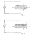
- Fig. 2
- eine schematische Darstellung eines erfindungsgemässen Entladungsreaktors gemäss einer zweiten Ausführungsform und
- Fig.3
- die Oberfläche eines Blocks von für die Verwendung in erfindungsgemässen Entladungsreaktoren geeignetem offenporigem Material.
- Fig. 1
- 1 shows a schematic illustration of a discharge reactor according to the invention in accordance with a first embodiment,
- Fig. 2
- a schematic representation of an inventive discharge reactor according to a second embodiment and
- Fig. 3
- the surface of a block of open-pore material suitable for use in the discharge reactors according to the invention.
Der Entladungsreaktor weist jeweils eine erste Elektrode 1
und eine zweite Elektrode 2 auf, an die eine Speisespannungsquelle
3 gelegt ist. Die Elektroden 1, 2 können
verschiedene geometrische Formen aufweisen. Insbesondere
können sie als parallele beabstandete Platten oder als
vorzugsweise konzentrisch angeordnete Rohre ausgebildet
sein. Vor allem die letztere Konfiguration wird gern
gewählt, wobei dann eine Vielzahl von Entladungsreaktoren
parallel zu einer wabenartig aufgebauten, zwischen den
Reaktoren von Kühlwasser durchströmten Batterie
zusammengefasst und auch elektrisch parallelgeschaltet ist.
Mit einer derartigen Anordnung kann auf kleinem Raum eine
hohe Produktionsleistung erzielt werden.The discharge reactor has a
Die Speisespannungsquelle 3 liefert eine Wechselspannung,
deren Frequenz zwischen einigen Hz und einigen GHz liegen
kann. Da nach (1) die Leistungsaufnahme des Entladungsreaktors
innerhalb gewisser Grenzen proportional zur
Frequenz ist, werden heute im Interesse einer hohen Ausbeute
im allgemeinen hohe, im MHz- oder sogar GHz-Bereich liegende
Frequenzen bevorzugt. Die Amplitude muss so gross sein, dass
im Entladungsspalt die Zündspannung erreicht und bei jeder
Halbwelle Mikroentladungen ausgelöst werden.The
Der zwischen der ersten Elektrode 1 und der zweiten
Elektrode 2 liegende Spalt ist beim Entladungsreaktor gemäss
der ersten Ausführungsform (Fig. 1) ganz von einer Schicht
aus einem Füllstoff ausgefüllt, einem starren offenporigen
Material, welches auch als die Mikroentladungen begrenzendes
Dielektrikum wirkt. Das starre offenporige Material ist in
Form eines festen Blocks 4 zwischen den Elektroden
angeordnet.The one between the
Zwischen den Elektroden 1, 2 wird ein Gasstrom (Pfeile)
durchgeleitet, in welchem durch die in den Poren des Blocks
4 ablaufende stille Entladung die gewünschten chemischen
Umsetzungen ausgelöst werden. Das aus dem Entladungsspalt
abgezogene Gas kann dann mit physikalischen oder chemischen
Methoden weiterverarbeitet und z. B. die gewünschten
Produkte isoliert werden. Die chemischen Umsetzungen können
u. U. durch Katalysatoren im Block 4 unterstützt oder
überhaupt erst ermöglicht werden. Statt parallel zu den
Elektroden kann der Gasstrom auch durch die Elektroden
geführt werden, die dann natürlich gasdurchlässig
ausgebildet sein müssen, z. B. als poröse Sinterplatten oder
perforierte Metallmembranen oder -platten.A gas flow (arrows) is between the
Obwohl der Block 4 als Schutz gegen Durchschläge in der
Regel ausreicht, kann, wie bei der zweiten Ausführungsform
gemäss Fig. 2 dargestellt, zur diesbezüglichen Sicherung das
Dielektrikum durch eine zwischen den Elektroden 1, 2
durchgehend angeordnete Sperrschicht 5 aus massivem Material
verstärkt sein. Es kann sich dabei z. B. um Glas, Quarz,
Keramik oder ein anderes geeignetes nichtleitendes Material
handeln. Die Schicht kann direkt an einer der Elektroden,
z. B. wie dargestellt an der ersten Elektrode 1 oder auch
von beiden Elektroden beabstandet angeordnet sein.Although block 4 serves as protection against breakdowns in the
Rule is sufficient, as in the
Das starre offenporige Material des Blocks 4 weist ein festes Gerüst 6 (Fig. 3) auf, das das Volumen des Entladungsspalts in eine Vielzahl offener, miteinander verbundener Poren 7 abteilt. Das Gerüst muss aus nichtleitendem Material bestehen, das gegenüber Mikroentladungen resistent und chemisch inert ist. In letzterer Hinsicht hängen die spezifischen Anforderungen vom Anwendungsgebiet ab. Die optimale Porengrösse ist, wie sich aus dem weiter oben im Zusammenhang mit der Leistungsaufnahme im Entladungsspalt Auseinandergesetzten ergibt, von den geometrischen und elektrischen Randbedingungen abhängig. In der Regel dürfte sie in der Grössenordnung von 0,1 mm, etwa zwischen 0,05 mm und 0,2 mm liegen. Günstig im Sinne einer hohen Ausbeute sind auch ein grosses Reaktionsvolumen, d. h. eine hohe Porosität von mindestens 50%, vorzugsweise 80-90% oder mehr und eine hohe Dielektrizitätskonstante, die etwa zwischen 3 und 20 liegen kann. Die erwünschte Stabilisierung der Gastemperatur wird durch hohe Wärmeleitfähigkeit und Wärmekapazität begünstigt. The rigid open-pore material of the block 4 has fixed framework 6 (Fig. 3) on the volume of Discharge gap in a variety of open, together connected pores 7. The scaffold must be out non-conductive material that exist Micro discharge is resistant and chemically inert. In the latter, the specific requirements depend on Area of application. The optimal pore size is how from the above in connection with the power consumption in the discharge gap results from depending on the geometric and electrical conditions. As a rule, it should be of the order of 0.1 mm, are approximately between 0.05 mm and 0.2 mm. Favorable in the sense a high yield is also a large reaction volume, d. H. a high porosity of at least 50%, preferably 80-90% or more and a high dielectric constant that can be between 3 and 20. The desired one The gas temperature is stabilized by high Thermal conductivity and heat capacity favored.
Diese Anforderungen werden von verschiedenen bekannten Stoffen erfüllt, insbesondere von porösem Glas und porösem Quarz, der sich wegen seiner UV-Durchlässigkeit auch für die Anwendung in Excimer-Lampen eignet. Sehr günstig ist auch poröse Keramik, wie sie von der Firma Bridgestone unter der Bezeichnung Ceramic Foam angeboten wird (Ceramic Foam, Technical Report No. 1). Dieses Material zeichnet sich durch hohe Porosität (80-90%), niedriges spezifisches Gewicht, hohe Hitzebeständigkeit (bis 1'150°C) und chemische Resistenz aus. Ausserdem ist der Druckabfall des Gasstroms verhältnismässig gering. Auch die Verwendung von porösem keramischem Sintermaterial ist möglich.These requirements are known by several Substances met, especially porous glass and porous Quartz, which is also suitable for UV radiation Suitable for use in excimer lamps. It is also very cheap porous ceramics, such as those from Bridgestone under the Ceramic Foam is offered (Ceramic Foam, Technical Report No. 1). This material stands out high porosity (80-90%), low specific weight, high heat resistance (up to 1,150 ° C) and chemical Resistance. In addition, the pressure drop in the gas flow relatively small. Even the use of porous ceramic sintered material is possible.
Alle erwähnten Materialien sind mechanisch sehr stabil, isbesondere sind ihre funktionswichtigen Eigenschaften mechanischen Belastungen gegenüber robust. Die Porengrösse ist in der Regel gut definiert und schwankt verhältnismässig wenig.All materials mentioned are mechanically very stable, Their functional properties are particularly important mechanical loads compared to robust. The pore size is usually well defined and fluctuates proportionately little.
Erfindungsgemässe Entladungsreaktoren eignen sich praktisch für alle bekannten Anwendungen bekannter gattungsgemässer Reaktoren. Insbesondere ist dabei an die Ozonerzeugung zu denken sowie an die Erzeugung von Methanol aus CO2 und H2 und von Synthesegas (CO und H2) aus CO2 und CH4. Zur Erzeugung von Methanol werden CO2 und H2 durch den Entladungsreaktor geleitet und unter der Einwirkung der stillen Entladung z. T. zu Methanol und Wasser umgesetzt. Bei dieser Reaktion werden Cu/ZrO2- oder Cu/ZnO-Katalysatoren eingesetzt. Bei der im übrigen analogen Erzeugung von Synthesegas können z. B. Nickelverbindungen als Katalysatoren dienen.Discharge reactors according to the invention are practically suitable for all known applications of known generic reactors. Particular attention should be paid to the generation of ozone and the production of methanol from CO 2 and H 2 and synthesis gas (CO and H 2 ) from CO 2 and CH4. To produce methanol, CO 2 and H 2 are passed through the discharge reactor and, for example, under the influence of the silent discharge. T. converted to methanol and water. Cu / ZrO 2 or Cu / ZnO catalysts are used in this reaction. In the rest of the analog generation of synthesis gas z. B. nickel compounds serve as catalysts.
Beim erfindungsgemässen Entladungsreaktor kann nun das
Gerüst 6 des Blocks 4 mit Katalysatormaterial beschichtet
oder versetzt sein. Zur Beschichtung können z. B. feste
Kupfer- und Zinkverbindungen usw. in einem Lösungsmittel
gelöst, dann zusammen mit demselben verdampft und aus der
Gasphase an den Wänden der Poren 7 abgeschieden werden. Auch
Abscheidung unmittelbar aus gasförmigen metallorganischen
Verbindungen ist möglich. Die Abscheidung kann durch Anheben
der Temperatur oder eventuell zusätzlich durch Zünden einer
stillen Entladung ausgelöst werden. Es kann dann ein
Oxidationsschritt folgen, bei dem das Material des Blocks 4
Luft oder Sauerstoff ausgesetzt wird und Konditionierung in
einer wasserstoffhaltigen Atmosphäre. Auch bei diesen
Schritten können Temperaturbehandlung und stille Entladung
eingesetzt werden.In the discharge reactor according to the invention, this can now be done
- 11
- erste Elektrodefirst electrode
- 22nd
- zweite Elektrodesecond electrode
- 33rd
- SpeisespannungsquelleSupply voltage source
- 44th
- Block aus starrem offenporigem MaterialBlock made of rigid, open-pore material
- 55
- Sperrschicht aus massivem MaterialSolid material barrier layer
- 66
- Gerüstframework
- 77
- PorenPores
Claims (13)
Applications Claiming Priority (2)
| Application Number | Priority Date | Filing Date | Title |
|---|---|---|---|
| DE19739181 | 1997-09-08 | ||
| DE19739181A DE19739181A1 (en) | 1997-09-08 | 1997-09-08 | Discharge reactor and use of the same |
Publications (2)
| Publication Number | Publication Date |
|---|---|
| EP0900591A1 true EP0900591A1 (en) | 1999-03-10 |
| EP0900591B1 EP0900591B1 (en) | 2002-10-23 |
Family
ID=7841517
Family Applications (1)
| Application Number | Title | Priority Date | Filing Date |
|---|---|---|---|
| EP98810849A Expired - Lifetime EP0900591B1 (en) | 1997-09-08 | 1998-08-27 | Electric discharge reactor |
Country Status (7)
| Country | Link |
|---|---|
| US (1) | US6136278A (en) |
| EP (1) | EP0900591B1 (en) |
| JP (1) | JPH11128728A (en) |
| AU (1) | AU728973B2 (en) |
| CA (1) | CA2246214A1 (en) |
| DE (2) | DE19739181A1 (en) |
| NO (1) | NO984094L (en) |
Cited By (4)
| Publication number | Priority date | Publication date | Assignee | Title |
|---|---|---|---|---|
| EP1074535A1 (en) * | 1999-08-05 | 2001-02-07 | Abb Research Ltd. | Process for the synthesis of hydrocarbons |
| FR2814452A1 (en) * | 2000-09-28 | 2002-03-29 | Peugeot Citroen Automobiles Sa | HYDROGEN GENERATOR AND HYDROGEN PRODUCTION APPARATUS EQUIPPED WITH SUCH GENERATOR |
| WO2011113713A1 (en) * | 2010-03-17 | 2011-09-22 | Annett Hartmann | Arrangement and method for the optimized performance of chemical reactions and reactor for same |
| EP3159305A1 (en) * | 2015-10-21 | 2017-04-26 | Xylem IP Management S.à.r.l. | Generating ozone with direct cooled plasma channels |
Families Citing this family (25)
| Publication number | Priority date | Publication date | Assignee | Title |
|---|---|---|---|---|
| ATE201331T1 (en) * | 1997-09-09 | 2001-06-15 | Aea Technology Plc | TREATMENT OF EXHAUST GASES |
| DE19757936B4 (en) * | 1997-12-27 | 2005-08-25 | Abb Research Ltd. | Process for producing a H2-CO gas mixture |
| DE19931366A1 (en) * | 1999-07-07 | 2001-02-01 | T E M Gmbh | Flat assembly for the electrical generation of a plasma in air |
| US6488838B1 (en) * | 1999-08-17 | 2002-12-03 | Battelle Memorial Institute | Chemical reactor and method for gas phase reactant catalytic reactions |
| US6611237B2 (en) * | 2000-11-30 | 2003-08-26 | The Regents Of The University Of California | Fluidic self-assembly of active antenna |
| EP1222961A3 (en) * | 2001-01-10 | 2002-08-28 | Abb Research Ltd. | Method of forming a zeolite layer on a substrate |
| EP1373132A1 (en) * | 2001-03-21 | 2004-01-02 | Accentus plc | Production of hydrogen |
| GB0113716D0 (en) * | 2001-06-06 | 2001-07-25 | Accentus Plc | Porous filtration materials |
| US6660061B2 (en) | 2001-10-26 | 2003-12-09 | Battelle Memorial Institute | Vapor purification with self-cleaning filter |
| KR100479990B1 (en) * | 2002-04-08 | 2005-03-30 | 이동훈 | Plasma reactor |
| US20030194358A1 (en) * | 2002-04-15 | 2003-10-16 | Minter Bruce E. | Ozone generator |
| US20040206618A1 (en) * | 2003-04-16 | 2004-10-21 | Voecks Gerald E. | Foam type catalyst system in non-thermal plasma catalytic reactor |
| DE10326424A1 (en) * | 2003-06-10 | 2004-12-30 | Solar Dynamics Gmbh | Thermodynamic energy conversion facility employs microprocessor for the targeted influence of heat transmission |
| JP4095620B2 (en) * | 2004-05-07 | 2008-06-04 | キヤノン株式会社 | Gas processing equipment |
| KR100561166B1 (en) * | 2004-12-07 | 2006-03-15 | 한국과학기술연구원 | The apparatus and method for preparing synthesis gas by using barrier discharge reaction |
| US20060119278A1 (en) * | 2004-12-07 | 2006-06-08 | Canon Kabushiki Kaisha | Gas decomposition apparatus and gas treatment cartridge |
| US7622088B2 (en) * | 2005-09-15 | 2009-11-24 | Gm Global Technology Operations, Inc. | Rapid activation catalyst system in a non-thermal plasma catalytic reactor |
| CN101912761B (en) * | 2010-07-05 | 2014-02-19 | 洪昆喨 | Dielectric discharge reactor of uniform electric field |
| US9117616B2 (en) * | 2012-07-13 | 2015-08-25 | Sp Tech Co., Ltd. | Dielectric barrier discharge-type electrode structure for generating plasma having conductive body protrusion on electrodes |
| US9114356B2 (en) * | 2012-09-20 | 2015-08-25 | Clean Air Group, Inc. | Fiberglass dielectric barrier ionization discharge device |
| DE102013019057B4 (en) | 2013-11-15 | 2018-02-15 | Cinogy Gmbh | Apparatus for treating a body surface of a living body |
| DE102016207370A1 (en) | 2016-04-29 | 2017-11-02 | Airbus Ds Gmbh | Gas inlet for an ion engine |
| EP3960700A4 (en) * | 2019-04-23 | 2022-04-20 | Mitsubishi Electric Corporation | Gas production system and gas production method |
| CN113511955A (en) * | 2021-06-03 | 2021-10-19 | 中国华能集团清洁能源技术研究院有限公司 | Device and method for synthesizing methanol by using carbon dioxide and water |
| DE102021123883A1 (en) | 2021-09-15 | 2023-03-16 | Synreform GmbH | Cracking and synthesis of hydrogen-containing gas using dielectric barrier discharge |
Citations (7)
| Publication number | Priority date | Publication date | Assignee | Title |
|---|---|---|---|---|
| US3674666A (en) * | 1970-08-19 | 1972-07-04 | Richard N Foster | Enhancing reaction rates |
| US4737885A (en) * | 1986-01-21 | 1988-04-12 | Nippon Paint Co., Ltd. | Plasma generator |
| US4954320A (en) * | 1988-04-22 | 1990-09-04 | The United States Of America As Represented By The Secretary Of The Army | Reactive bed plasma air purification |
| WO1991016528A1 (en) * | 1990-04-23 | 1991-10-31 | Fleck Carl M | Process and device for removing particles from exhaust gases |
| DE4220865A1 (en) * | 1991-08-15 | 1993-02-18 | Asea Brown Boveri | Hydrogenation of carbon di:oxide esp. to methane or methanol in plasma - which can operate at low temp. and low pressure, using hydrogen@ or water vapour |
| DE4416676A1 (en) * | 1994-05-11 | 1995-11-23 | Siemens Ag | Device for the detoxification of exhaust gases from mobile systems |
| US5609736A (en) * | 1995-09-26 | 1997-03-11 | Research Triangle Institute | Methods and apparatus for controlling toxic compounds using catalysis-assisted non-thermal plasma |
Family Cites Families (13)
| Publication number | Priority date | Publication date | Assignee | Title |
|---|---|---|---|---|
| SE371453C (en) * | 1973-03-26 | 1978-01-12 | Skf Ind Trading & Dev | KIT FOR PRODUCTION OF REDUCTION GAS |
| BE814899A (en) * | 1974-05-10 | 1974-11-12 | PROCESS FOR MANUFACTURING HOT REDUCING GAS. | |
| US3970567A (en) * | 1975-04-17 | 1976-07-20 | W. R. Grace & Co. | Ozonizer with absorption of ozone |
| CH648534A5 (en) * | 1981-07-10 | 1985-03-29 | Bbc Brown Boveri & Cie | METHOD AND DEVICE FOR PRODUCING OZONE. |
| CH660875A5 (en) * | 1984-10-25 | 1987-05-29 | Bbc Brown Boveri & Cie | OZONE GENERATOR WITH A CERAMIC-BASED DIELECTRIC. |
| SE453920B (en) * | 1985-03-01 | 1988-03-14 | Skf Steel Eng Ab | SET AND DEVICE FOR GASING OF FOSSIL FUEL AND REFORM OF GAS FUEL |
| JPH01103903A (en) * | 1987-10-16 | 1989-04-21 | Teru Kyushu Kk | Ozonizer |
| JPH01161591A (en) * | 1987-12-18 | 1989-06-26 | Hitachi Ltd | On-line handwritten-character inputting device |
| DE4140497C2 (en) * | 1991-12-09 | 1996-05-02 | Heraeus Noblelight Gmbh | High-power radiation |
| US5254231A (en) * | 1992-08-03 | 1993-10-19 | Battelle Memorial Institute | Method and apparatus for chemically altering fluids in continuous flow |
| JPH0838881A (en) * | 1994-08-01 | 1996-02-13 | Toshiba Corp | Plasma chemical reaction apparatus |
| JP3301260B2 (en) * | 1995-02-28 | 2002-07-15 | いすゞ自動車株式会社 | Transmission control device for toroidal type continuously variable transmission |
| DE19518970C1 (en) * | 1995-05-23 | 1996-11-21 | Fraunhofer Ges Forschung | Method and device for treating exhaust gas |
-
1997
- 1997-09-08 DE DE19739181A patent/DE19739181A1/en not_active Withdrawn
-
1998
- 1998-08-27 DE DE59806029T patent/DE59806029D1/en not_active Expired - Fee Related
- 1998-08-27 EP EP98810849A patent/EP0900591B1/en not_active Expired - Lifetime
- 1998-09-01 US US09/144,971 patent/US6136278A/en not_active Expired - Fee Related
- 1998-09-02 CA CA002246214A patent/CA2246214A1/en not_active Abandoned
- 1998-09-04 JP JP10250994A patent/JPH11128728A/en active Pending
- 1998-09-04 NO NO984094A patent/NO984094L/en not_active Application Discontinuation
- 1998-09-08 AU AU83180/98A patent/AU728973B2/en not_active Ceased
Patent Citations (7)
| Publication number | Priority date | Publication date | Assignee | Title |
|---|---|---|---|---|
| US3674666A (en) * | 1970-08-19 | 1972-07-04 | Richard N Foster | Enhancing reaction rates |
| US4737885A (en) * | 1986-01-21 | 1988-04-12 | Nippon Paint Co., Ltd. | Plasma generator |
| US4954320A (en) * | 1988-04-22 | 1990-09-04 | The United States Of America As Represented By The Secretary Of The Army | Reactive bed plasma air purification |
| WO1991016528A1 (en) * | 1990-04-23 | 1991-10-31 | Fleck Carl M | Process and device for removing particles from exhaust gases |
| DE4220865A1 (en) * | 1991-08-15 | 1993-02-18 | Asea Brown Boveri | Hydrogenation of carbon di:oxide esp. to methane or methanol in plasma - which can operate at low temp. and low pressure, using hydrogen@ or water vapour |
| DE4416676A1 (en) * | 1994-05-11 | 1995-11-23 | Siemens Ag | Device for the detoxification of exhaust gases from mobile systems |
| US5609736A (en) * | 1995-09-26 | 1997-03-11 | Research Triangle Institute | Methods and apparatus for controlling toxic compounds using catalysis-assisted non-thermal plasma |
Cited By (10)
| Publication number | Priority date | Publication date | Assignee | Title |
|---|---|---|---|---|
| EP1074535A1 (en) * | 1999-08-05 | 2001-02-07 | Abb Research Ltd. | Process for the synthesis of hydrocarbons |
| US6326407B1 (en) | 1999-08-05 | 2001-12-04 | Abb Research Ltd. | Hydrocarbon synthesis |
| FR2814452A1 (en) * | 2000-09-28 | 2002-03-29 | Peugeot Citroen Automobiles Sa | HYDROGEN GENERATOR AND HYDROGEN PRODUCTION APPARATUS EQUIPPED WITH SUCH GENERATOR |
| EP1193218A1 (en) * | 2000-09-28 | 2002-04-03 | Peugeot Citroen Automobiles SA | Hydrogen generator and process for generating hydrogen for supplying a fuel cell |
| WO2011113713A1 (en) * | 2010-03-17 | 2011-09-22 | Annett Hartmann | Arrangement and method for the optimized performance of chemical reactions and reactor for same |
| EP3159305A1 (en) * | 2015-10-21 | 2017-04-26 | Xylem IP Management S.à.r.l. | Generating ozone with direct cooled plasma channels |
| WO2017067991A1 (en) * | 2015-10-21 | 2017-04-27 | Xylem Ip Management S.À R.L. | Ozone generation with directly cooled plasma channels |
| AU2016341160B2 (en) * | 2015-10-21 | 2019-04-18 | Xylem Ip Management S.À R.L. | Ozone generation with directly cooled plasma channels |
| RU2696471C1 (en) * | 2015-10-21 | 2019-08-01 | Ксилем Ай Пи Менеджмент С.А Р.Л. | Obtaining ozone in a plasma plant with direct cooling |
| US10919766B2 (en) | 2015-10-21 | 2021-02-16 | Xylem Ip Management S.À R.L. | Ozone generation with directly cooled plasma channels |
Also Published As
| Publication number | Publication date |
|---|---|
| NO984094L (en) | 1999-03-09 |
| NO984094D0 (en) | 1998-09-04 |
| DE19739181A1 (en) | 1999-03-11 |
| DE59806029D1 (en) | 2002-11-28 |
| AU8318098A (en) | 1999-03-18 |
| US6136278A (en) | 2000-10-24 |
| CA2246214A1 (en) | 1999-03-08 |
| EP0900591B1 (en) | 2002-10-23 |
| JPH11128728A (en) | 1999-05-18 |
| AU728973B2 (en) | 2001-01-25 |
Similar Documents
| Publication | Publication Date | Title |
|---|---|---|
| EP0900591B1 (en) | Electric discharge reactor | |
| EP1095907B1 (en) | Process for the plasma-catalytic preparation of ammonia | |
| EP0081081B1 (en) | Process and apparatus for co2 laser excitation | |
| DE69731767T2 (en) | METHOD AND DEVICES FOR THE PRODUCTION OF HYDROGEN BY PLASMAREFORMING | |
| DE112013004853B4 (en) | Hydrogen generating device and fuel cell system with hydrogen generating device | |
| DE4326360C1 (en) | Method and device for producing a fuel mixture | |
| DE19903533A1 (en) | Process for the selective catalytic reduction of nitrogen oxides in oxygen-containing exhaust gases | |
| EP0934772B1 (en) | Reactor for carrying out catalytic chemical reactions, in particular a reactor for methanol reforming | |
| DE4220865A1 (en) | Hydrogenation of carbon di:oxide esp. to methane or methanol in plasma - which can operate at low temp. and low pressure, using hydrogen@ or water vapour | |
| DE19813053A1 (en) | Reactor unit for a catalytic chemical reaction, especially for catalytic methanol reforming | |
| DE1900644A1 (en) | Method and device for using the electric arc for chemical reactions | |
| DE2539715C3 (en) | Device for the production of ozone | |
| DE10219643B4 (en) | Process for the preparation of catalysts | |
| DE102011053142A1 (en) | Electrolyzer, useful for generating hydrogen and oxygen by electrochemical decomposition of water, comprises housing with electrodes connected to poles of direct current supply source and separated by diaphragm, and gas separation chamber | |
| DE102006007773B4 (en) | Arrangement for splitting water | |
| WO2012095213A1 (en) | Method for producing syngas containing carbon monoxide (co) and hydrogen (h2) | |
| EP1769551B1 (en) | Silver gas diffusion electrode for use in air containing co2, and method for the production thereof | |
| DE19819372A1 (en) | Process for reducing the nitrogen oxide content of the exhaust gases of an internal combustion engine | |
| DE3731168A1 (en) | Device for producing cold plasma for AC voltage excitation in the kHz band, preferably for producing ozone, and a method for manufacturing the device | |
| EP1995352A1 (en) | Method for creating a flammable mixture | |
| DE19717889C2 (en) | Device and method for the decomposition of toxic pollutants in exhaust gases from combustion processes | |
| DE19907796A1 (en) | Reactor catalytically-converting hydrocarbon in presence of oxygen, to produce very pure hydrogen for use in e.g. vehicle fuel cells, employs selectively-permeable membranes for oxygen and hydrogen | |
| WO2023073242A1 (en) | Process and apparatus for synthesis of organic carbon compounds | |
| DE10163474A1 (en) | Method and device for treating and / or reforming gaseous fuels and associated application | |
| EP1456118B1 (en) | Method and device for converting a fuel |
Legal Events
| Date | Code | Title | Description |
|---|---|---|---|
| PUAI | Public reference made under article 153(3) epc to a published international application that has entered the european phase |
Free format text: ORIGINAL CODE: 0009012 |
|
| AK | Designated contracting states |
Kind code of ref document: A1 Designated state(s): CH DE FR GB IT LI NL SE |
|
| AX | Request for extension of the european patent |
Free format text: AL;LT;LV;MK;RO;SI |
|
| 17P | Request for examination filed |
Effective date: 19990824 |
|
| AKX | Designation fees paid |
Free format text: CH DE FR GB IT LI NL SE |
|
| 17Q | First examination report despatched |
Effective date: 20000602 |
|
| GRAG | Despatch of communication of intention to grant |
Free format text: ORIGINAL CODE: EPIDOS AGRA |
|
| GRAG | Despatch of communication of intention to grant |
Free format text: ORIGINAL CODE: EPIDOS AGRA |
|
| GRAH | Despatch of communication of intention to grant a patent |
Free format text: ORIGINAL CODE: EPIDOS IGRA |
|
| RIC1 | Information provided on ipc code assigned before grant |
Free format text: 7B 01J 19/08 A, 7B 01J 35/04 B |
|
| RTI1 | Title (correction) |
Free format text: ELECTRIC DISCHARGE REACTOR |
|
| GRAH | Despatch of communication of intention to grant a patent |
Free format text: ORIGINAL CODE: EPIDOS IGRA |
|
| GRAA | (expected) grant |
Free format text: ORIGINAL CODE: 0009210 |
|
| AK | Designated contracting states |
Kind code of ref document: B1 Designated state(s): CH DE FR GB IT LI NL SE |
|
| PG25 | Lapsed in a contracting state [announced via postgrant information from national office to epo] |
Ref country code: NL Free format text: LAPSE BECAUSE OF FAILURE TO SUBMIT A TRANSLATION OF THE DESCRIPTION OR TO PAY THE FEE WITHIN THE PRESCRIBED TIME-LIMIT Effective date: 20021023 Ref country code: IT Free format text: LAPSE BECAUSE OF FAILURE TO SUBMIT A TRANSLATION OF THE DESCRIPTION OR TO PAY THE FEE WITHIN THE PRESCRIBED TIME-LIMIT;WARNING: LAPSES OF ITALIAN PATENTS WITH EFFECTIVE DATE BEFORE 2007 MAY HAVE OCCURRED AT ANY TIME BEFORE 2007. THE CORRECT EFFECTIVE DATE MAY BE DIFFERENT FROM THE ONE RECORDED. Effective date: 20021023 |
|
| REG | Reference to a national code |
Ref country code: GB Ref legal event code: FG4D Free format text: NOT ENGLISH |
|
| REG | Reference to a national code |
Ref country code: CH Ref legal event code: EP |
|
| REF | Corresponds to: |
Ref document number: 59806029 Country of ref document: DE Date of ref document: 20021128 |
|
| PG25 | Lapsed in a contracting state [announced via postgrant information from national office to epo] |
Ref country code: SE Free format text: LAPSE BECAUSE OF FAILURE TO SUBMIT A TRANSLATION OF THE DESCRIPTION OR TO PAY THE FEE WITHIN THE PRESCRIBED TIME-LIMIT Effective date: 20030123 |
|
| REG | Reference to a national code |
Ref country code: CH Ref legal event code: NV Representative=s name: ABB SCHWEIZ AG |
|
| GBT | Gb: translation of ep patent filed (gb section 77(6)(a)/1977) |
Effective date: 20030214 |
|
| NLV1 | Nl: lapsed or annulled due to failure to fulfill the requirements of art. 29p and 29m of the patents act | ||
| ET | Fr: translation filed | ||
| PGFP | Annual fee paid to national office [announced via postgrant information from national office to epo] |
Ref country code: CH Payment date: 20030728 Year of fee payment: 6 Ref country code: GB Payment date: 20030728 Year of fee payment: 6 |
|
| PGFP | Annual fee paid to national office [announced via postgrant information from national office to epo] |
Ref country code: DE Payment date: 20030805 Year of fee payment: 6 |
|
| PGFP | Annual fee paid to national office [announced via postgrant information from national office to epo] |
Ref country code: FR Payment date: 20030813 Year of fee payment: 6 |
|
| PLBE | No opposition filed within time limit |
Free format text: ORIGINAL CODE: 0009261 |
|
| STAA | Information on the status of an ep patent application or granted ep patent |
Free format text: STATUS: NO OPPOSITION FILED WITHIN TIME LIMIT |
|
| 26N | No opposition filed |
Effective date: 20030724 |
|
| PG25 | Lapsed in a contracting state [announced via postgrant information from national office to epo] |
Ref country code: GB Free format text: LAPSE BECAUSE OF NON-PAYMENT OF DUE FEES Effective date: 20040827 |
|
| PG25 | Lapsed in a contracting state [announced via postgrant information from national office to epo] |
Ref country code: LI Free format text: LAPSE BECAUSE OF NON-PAYMENT OF DUE FEES Effective date: 20040831 Ref country code: CH Free format text: LAPSE BECAUSE OF NON-PAYMENT OF DUE FEES Effective date: 20040831 |
|
| PG25 | Lapsed in a contracting state [announced via postgrant information from national office to epo] |
Ref country code: DE Free format text: LAPSE BECAUSE OF NON-PAYMENT OF DUE FEES Effective date: 20050301 |
|
| REG | Reference to a national code |
Ref country code: CH Ref legal event code: PL |
|
| GBPC | Gb: european patent ceased through non-payment of renewal fee |
Effective date: 20040827 |
|
| PG25 | Lapsed in a contracting state [announced via postgrant information from national office to epo] |
Ref country code: FR Free format text: LAPSE BECAUSE OF NON-PAYMENT OF DUE FEES Effective date: 20050429 |
|
| REG | Reference to a national code |
Ref country code: FR Ref legal event code: ST |