EP0900753A2 - Method and unit for feeding blanks to a user machine - Google Patents
Method and unit for feeding blanks to a user machine Download PDFInfo
- Publication number
- EP0900753A2 EP0900753A2 EP98116687A EP98116687A EP0900753A2 EP 0900753 A2 EP0900753 A2 EP 0900753A2 EP 98116687 A EP98116687 A EP 98116687A EP 98116687 A EP98116687 A EP 98116687A EP 0900753 A2 EP0900753 A2 EP 0900753A2
- Authority
- EP
- European Patent Office
- Prior art keywords
- blank
- pickup
- blanks
- conveying surface
- flat
- Prior art date
- Legal status (The legal status is an assumption and is not a legal conclusion. Google has not performed a legal analysis and makes no representation as to the accuracy of the status listed.)
- Granted
Links
Images


Classifications
-
- B—PERFORMING OPERATIONS; TRANSPORTING
- B65—CONVEYING; PACKING; STORING; HANDLING THIN OR FILAMENTARY MATERIAL
- B65H—HANDLING THIN OR FILAMENTARY MATERIAL, e.g. SHEETS, WEBS, CABLES
- B65H3/00—Separating articles from piles
- B65H3/44—Simultaneously, alternately, or selectively separating articles from two or more piles
-
- B—PERFORMING OPERATIONS; TRANSPORTING
- B65—CONVEYING; PACKING; STORING; HANDLING THIN OR FILAMENTARY MATERIAL
- B65H—HANDLING THIN OR FILAMENTARY MATERIAL, e.g. SHEETS, WEBS, CABLES
- B65H3/00—Separating articles from piles
- B65H3/08—Separating articles from piles using pneumatic force
- B65H3/0808—Suction grippers
- B65H3/085—Suction grippers separating from the bottom of pile
Definitions
- the present invention relates to a method of feeding blanks to a user machine.
- Blanks are fed to a user machine, such as a packing machine for folding the blanks about respective products, by feed units, which comprise a hopper containing a stack of blanks and having an open end from which the blanks are withdrawn; a transfer device located in front of, and for successively withdrawing the blanks from, the open end of the hopper; and a conveying device associated with the transfer device and for conveying the blanks to a user station of the packing machine.
- feed units which comprise a hopper containing a stack of blanks and having an open end from which the blanks are withdrawn; a transfer device located in front of, and for successively withdrawing the blanks from, the open end of the hopper; and a conveying device associated with the transfer device and for conveying the blanks to a user station of the packing machine.
- Known transfer devices comprise one or more pickup heads, each of which travels cyclically past the open end of the hopper and past the conveying device to withdraw a respective blank, which adheres by suction to an outer surface of the head, and to feed the blank into a respective conveying seat on the conveying device, which is normally defined by a rotary drum for feeding the conveying seats along a circular path, or by a pocket conveyor for feeding the conveying seats along a straight linear path.
- the outer surface of the pickup head must be curved to roll along the open end of the hopper and gradually detach the respective blank from the stack, and to gradually insert the blank into the respective conveying seat by rolling along the bottom surface of the conveying seat, which may also be curved or, as in the case of a pocket conveyor, flat.
- feed units comprising pickup heads with flat regular outer surfaces, and which are guided by crank mechanisms along respective cyclic paths, the pickup portion of which is substantially perpendicular to the open end of the hopper, and the unloading portion of which is substantially tangent to the bottom surfaces of the conveying pockets.
- a method of feeding blanks to a user machine comprising the steps of withdrawing blanks from a pickup station by means of a transfer device having at least one pickup head movable cyclically through the pickup station and through an unloading station, the pickup head having a flat conveying surface and at least one push tooth projecting from the flat conveying surface, and the blank adhering by suction to the flat conveying surface and being arranged with a respective first lateral edge projecting from the flat conveying surface and with a respective second lateral edge contacting said push tooth; engaging the first lateral edge of the blank against a stop element of a conveying pocket movable continuously along a user path of the user machine extending through said unloading station; detaching the blank from said flat conveying surface; and pushing the blank, by means of the push tooth, against the stop element to secure the blank between the stop element and the push tooth and maintain a flat configuration of the blank until the blank is fully inserted inside said conveying pocket.
- the present invention also relates to a unit for feeding blanks to a user machine.
- a unit for feeding blanks to a user machine comprising at least one conveying pocket movable continuously along a user path of the user machine; a transfer device having at least one pickup head movable cyclically through a pickup station to withdraw a respective blank, and through an unloading station, located along said user path, to feed the blank to said conveying pocket, the pickup head comprising a flat conveying surface, at least one push tooth projecting from the flat conveying surface, and suction means by which the blank adheres to the flat conveying surface in such a manner that the blank has a respective first lateral edge projecting from the flat conveying surface and a respective second lateral edge contacting the push tooth, and said conveying pocket comprising a stop element for retaining the first lateral edge of the blank; and detaching means for detaching the blank from said flat conveying surface while maintaining the blank secured in a flat configuration between the stop element and the push tooth.
- Number 1 in Figure 1 indicates as a whole a unit for feeding blanks 2 to a user machine 3 defined, in particular, by a packing machine for folding blanks 2 about respective products (not shown).
- Unit 1 comprises a given N number of side by side hoppers 4 for feeding respective stacks 5 of blanks 2 to respective bottom openings 6 from which blanks 2 are withdrawn; a pocket conveyor 7 defining an input of machine 3 and having a number of conveying pockets 8 movable continuously in a given traveling direction D1 and along a packing path P1 extending beneath openings 6; and a transfer device 9 in turn comprising, for each hopper 4, a pickup head 10 movable along a respective feed path P2 extending between a pickup station S1 defined by respective opening 6, and a feed station S2 located along path P1 and where path P2 is substantially tangent to path P1.
- hoppers 4 are four in number
- transfer device 9 comprises four pickup heads 10 synchronized with one another to form, along conveyor 7, a succession 11 of blanks 2 (only one of which is shown in Figure 2).
- Each hopper 4 feeds respective stack 5 of blanks 2 by gravity to respective opening 6 along a vertical axis 4a of hopper 4; blanks 2 are arranged in respective stack 5 with respective major longitudinal axes 2a crosswise to axis 4a and direction D1; each opening 6 is parallel to a conveying branch 12 of conveyor 7; and, at pickup station S1, respective path P2 comprises a portion T along which respective head 10 moves back and forth, and which is parallel to axis 4a of respective hopper 4 and crosswise to opening 6.
- conveyor 7 comprises three side by side endless belts 13, 14, 15, which are so spaced as to define, along conveying branch 12 of conveyor 7, two openings 16 parallel to direction D1, and have respective series of shaped projections 17, 18, 19, the projections in each series being arranged with a given spacing. More specifically, belt 14 is located in an intermediate position between belts 13 and 15, with respective projections 18 offset, in direction D1, with respect to projections 17 and 19 of belts 13 and 15, whereas each projection 17 is aligned, crosswise to direction D1, with a corresponding projection 19. Each pocket 8 is defined by two aligned projections 17 and 19, and by a projection 18 located downstream from projections 17 and 19 in direction D1 and at a distance D adjustable according to the size of blanks 2.
- Each projection 17, 18, 19 comprises a substantially wedge-shaped free top portion 20 defined by two upwardly-converging lateral surfaces 21 connected by a rounded top surface 22; and a substantially parallelepiped bottom portion 23 connected to respective belt 13, 14, 15 and defined by two vertical surfaces 24 crosswise to conveying branch 12 and direction D1.
- Each pickup head 10 is fitted to a crank 26, which is located beneath respective opening 6, is offset laterally with respect to axis 4a of respective hopper 4, and is mounted for rotation about a respective horizontal axis 26a crosswise to direction D1.
- Each head 10 comprises a shaped body 25 fitted to a free end of crank 26 so as to rotate about an axis 25a parallel to axis 26a; and a suction plate 27 connected to body 25 and having a flat conveying surface 28 parallel to axis 25a.
- Surface 28 also extends partly over two lateral appendixes 29, which project from plate 27, are of a width approximately equal to but no greater than the width of openings 16, and are each provided with a respective push tooth 30 extending crosswise to surface 28 on the opposite side of surface 28 to body 25.
- Each plate 27 and respective appendixes 29 comprise a number of suction holes 31 connected to a known suction device (not shown) for retaining a blank 2 by suction on surface 28 as blank 2 is transferred from station S1 to station S2.
- each crank 26 oscillates about axis 26a between a raised position ( Figures 1 and 3a) in which head 10 is located at pickup station S1, and a lowered position ( Figures 3b-5f) in which crank 26 positions head 10 at such a distance from conveying branch 12 of conveyor 7 as to enable head 10 to insert respective blank 2 inside a respective pocket 8.
- transfer device 9 comprises two guides 32 for supporting blanks 2 and defined by respective rectangular section elements, which extend along path P1, alongside belts 13 and 15 and at a higher level than conveying branch 12 of conveyor 7 to substantially support the ends of blanks 2 inside pockets 8.
- Device 9 also comprises, for each station S2, two curved guide elements 33 located on either side of conveyor 7 and extending substantially along the trajectories traveled by push teeth 30 as plates 27 rotate about axes 25a; and two curved engaging elements 34, which are located in front of respective elements 33, are less sharply curved than elements 33, and define, with elements 33, two funnel-shaped channels 35 converging towards path P2.
- the elements 33 at the first of stations S2 along path P2 are formed in one piece from respective end portions of guides 32; elements 34 of each station S2 are connected to guides 32 by respective supports 36; and elements 33 at the other stations S2 are also connected to supports 36, each of which comprises a top plate 37 extending over guides 32 and at such a distance from guides 32 as to leave a gap 38 for the passage of blanks 2 inside pockets 8.
- feed unit 1 Operation of feed unit 1 will now be described with reference to Figures 3, 4 and 5 and to only one of pickup heads 10, since, besides being structurally identical, all four pickup heads 10 are also synchronized with one another to perform the same movements simultaneously.
- specific reference will also be made to blanks 2 of the type normally used in the packing industry, and which are defined laterally by two long edges 39 and 40 parallel to respective axes 2a.
- crank 26 is rotated (clockwise in Figures 3a and 3b) about axis 26a into the lowered position so as to withdraw blank 2 from hopper 4 and detach it from stack 5. Substantially at this point, plate 27 is rotated (anticlockwise in Figure 3b) by said actuating means, and blank 2 is gradually inserted inside channels 35 with respective edge 40 forwards.
- Blank 2 is detached from surface 28 simultaneously with deactivation of the suction device, but, as opposed to being released onto guides 33, is retained in a flat configuration between teeth 30 and projection 18, along surfaces 21 and 24 of which, edge 40 is eased right down to the bottom of pocket 8 with no deformation of blank 2.
- the rotation speed of crank 26 about axis 26a and the traveling speed of pockets 8 along path P1 are such that, firstly, blank 2 is pushed constantly by teeth 30 against projection 18, and, secondly, edge 40, on sliding into contact with surface 24 and guides 32, acts as the center of instantaneous rotation of blank 2 (Figure 4d), so that, as pocket 8 and teeth 30 continue moving forward, blank 2 is inserted inside pocket 8 in a position parallel to conveying branch 12 of conveyor 7 ( Figure 5e).
- each head 10 again operates in the same way as described above.
Abstract
Description
- The present invention relates to a method of feeding blanks to a user machine.
- Blanks are fed to a user machine, such as a packing machine for folding the blanks about respective products, by feed units, which comprise a hopper containing a stack of blanks and having an open end from which the blanks are withdrawn; a transfer device located in front of, and for successively withdrawing the blanks from, the open end of the hopper; and a conveying device associated with the transfer device and for conveying the blanks to a user station of the packing machine.
- Known transfer devices comprise one or more pickup heads, each of which travels cyclically past the open end of the hopper and past the conveying device to withdraw a respective blank, which adheres by suction to an outer surface of the head, and to feed the blank into a respective conveying seat on the conveying device, which is normally defined by a rotary drum for feeding the conveying seats along a circular path, or by a pocket conveyor for feeding the conveying seats along a straight linear path. In both cases, the outer surface of the pickup head must be curved to roll along the open end of the hopper and gradually detach the respective blank from the stack, and to gradually insert the blank into the respective conveying seat by rolling along the bottom surface of the conveying seat, which may also be curved or, as in the case of a pocket conveyor, flat.
- Known feed units of the above type have several drawbacks, mainly due to the outer surfaces of the pickup heads, the curved shape of which forms a curve in the blanks which is later reflected in the shape of the packages formed when the blanks are folded about the respective products. Moreover, to withdraw the blanks from the hopper, the pickup heads must bend the blanks even more sharply to detach each one separately from the stack, thus further accentuating the curvature of the blank.
- To overcome the above drawbacks, feed units have been devised comprising pickup heads with flat regular outer surfaces, and which are guided by crank mechanisms along respective cyclic paths, the pickup portion of which is substantially perpendicular to the open end of the hopper, and the unloading portion of which is substantially tangent to the bottom surfaces of the conveying pockets.
- Even these new feed units, however, are not without drawbacks, in that, despite the blanks being withdrawn substantially undeformed from the hopper, the way in which the blanks are fed into the conveying pockets is fairly complex and unreliable.
- It is an object of the present invention to provide a straightforward, low-cost method of feeding blanks to a user machine, designed to overcome the aforementioned drawbacks.
- According to the present invention, there is provided a method of feeding blanks to a user machine, the method being characterized by comprising the steps of withdrawing blanks from a pickup station by means of a transfer device having at least one pickup head movable cyclically through the pickup station and through an unloading station, the pickup head having a flat conveying surface and at least one push tooth projecting from the flat conveying surface, and the blank adhering by suction to the flat conveying surface and being arranged with a respective first lateral edge projecting from the flat conveying surface and with a respective second lateral edge contacting said push tooth; engaging the first lateral edge of the blank against a stop element of a conveying pocket movable continuously along a user path of the user machine extending through said unloading station; detaching the blank from said flat conveying surface; and pushing the blank, by means of the push tooth, against the stop element to secure the blank between the stop element and the push tooth and maintain a flat configuration of the blank until the blank is fully inserted inside said conveying pocket.
- The present invention also relates to a unit for feeding blanks to a user machine.
- According to the present invention, there is provided a unit for feeding blanks to a user machine, the unit being characterized by comprising at least one conveying pocket movable continuously along a user path of the user machine; a transfer device having at least one pickup head movable cyclically through a pickup station to withdraw a respective blank, and through an unloading station, located along said user path, to feed the blank to said conveying pocket, the pickup head comprising a flat conveying surface, at least one push tooth projecting from the flat conveying surface, and suction means by which the blank adheres to the flat conveying surface in such a manner that the blank has a respective first lateral edge projecting from the flat conveying surface and a respective second lateral edge contacting the push tooth, and said conveying pocket comprising a stop element for retaining the first lateral edge of the blank; and detaching means for detaching the blank from said flat conveying surface while maintaining the blank secured in a flat configuration between the stop element and the push tooth.
- A non-limiting embodiment of the present invention will be described by way of example with reference to the accompanying drawings, in which:
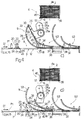
- Figure 1 shows a side view, with parts in section and parts removed for clarity, of a blank feed unit implementing the method according to the present invention;
- Figure 2 shows a larger-scale view in perspective of a detail of Figure 1;
- Figures 3, 4, 5 show smaller-scale side views of the Figure 2 detail in a succession of respective operating positions.
-
- Number 1 in Figure 1 indicates as a whole a unit for feeding
blanks 2 to auser machine 3 defined, in particular, by a packing machine for foldingblanks 2 about respective products (not shown). - Unit 1 comprises a given N number of side by
side hoppers 4 for feedingrespective stacks 5 ofblanks 2 torespective bottom openings 6 from whichblanks 2 are withdrawn; apocket conveyor 7 defining an input ofmachine 3 and having a number ofconveying pockets 8 movable continuously in a given traveling direction D1 and along a packing path P1 extending beneathopenings 6; and atransfer device 9 in turn comprising, for eachhopper 4, apickup head 10 movable along a respective feed path P2 extending between a pickup station S1 defined byrespective opening 6, and a feed station S2 located along path P1 and where path P2 is substantially tangent to path P1. In the example embodiment shown,hoppers 4 are four in number, andtransfer device 9 comprises fourpickup heads 10 synchronized with one another to form, alongconveyor 7, a succession 11 of blanks 2 (only one of which is shown in Figure 2). - Each
hopper 4 feedsrespective stack 5 ofblanks 2 by gravity torespective opening 6 along avertical axis 4a ofhopper 4;blanks 2 are arranged inrespective stack 5 with respective majorlongitudinal axes 2a crosswise toaxis 4a and direction D1; eachopening 6 is parallel to a conveyingbranch 12 ofconveyor 7; and, at pickup station S1, respective path P2 comprises a portion T along whichrespective head 10 moves back and forth, and which is parallel toaxis 4a ofrespective hopper 4 and crosswise to opening 6. - As shown in Figure 2,
conveyor 7 comprises three side by sideendless belts branch 12 ofconveyor 7, twoopenings 16 parallel to direction D1, and have respective series ofshaped projections belt 14 is located in an intermediate position betweenbelts respective projections 18 offset, in direction D1, with respect toprojections belts projection 17 is aligned, crosswise to direction D1, with acorresponding projection 19. Eachpocket 8 is defined by two alignedprojections projection 18 located downstream fromprojections blanks 2. Eachprojection free top portion 20 defined by two upwardly-converginglateral surfaces 21 connected by arounded top surface 22; and a substantiallyparallelepiped bottom portion 23 connected torespective belt vertical surfaces 24 crosswise to conveyingbranch 12 and direction D1. - Each
pickup head 10 is fitted to acrank 26, which is located beneathrespective opening 6, is offset laterally with respect toaxis 4a ofrespective hopper 4, and is mounted for rotation about a respectivehorizontal axis 26a crosswise to direction D1. Eachhead 10 comprises ashaped body 25 fitted to a free end ofcrank 26 so as to rotate about anaxis 25a parallel toaxis 26a; and asuction plate 27 connected tobody 25 and having aflat conveying surface 28 parallel toaxis 25a.Surface 28 also extends partly over twolateral appendixes 29, which project fromplate 27, are of a width approximately equal to but no greater than the width ofopenings 16, and are each provided with arespective push tooth 30 extending crosswise tosurface 28 on the opposite side ofsurface 28 tobody 25. Eachplate 27 andrespective appendixes 29 comprise a number ofsuction holes 31 connected to a known suction device (not shown) for retaining a blank 2 by suction onsurface 28 as blank 2 is transferred from station S1 to station S2. - By means of known actuating means (not shown), each
crank 26 oscillates aboutaxis 26a between a raised position (Figures 1 and 3a) in whichhead 10 is located at pickup station S1, and a lowered position (Figures 3b-5f) in whichcrank 26positions head 10 at such a distance from conveyingbranch 12 ofconveyor 7 as to enablehead 10 to insert respective blank 2 inside arespective pocket 8. - Finally,
transfer device 9 comprises twoguides 32 for supportingblanks 2 and defined by respective rectangular section elements, which extend along path P1, alongsidebelts branch 12 ofconveyor 7 to substantially support the ends ofblanks 2 insidepockets 8.Device 9 also comprises, for each station S2, twocurved guide elements 33 located on either side ofconveyor 7 and extending substantially along the trajectories traveled bypush teeth 30 asplates 27 rotate aboutaxes 25a; and two curvedengaging elements 34, which are located in front ofrespective elements 33, are less sharply curved thanelements 33, and define, withelements 33, two funnel-shaped channels 35 converging towards path P2. More specifically, theelements 33 at the first of stations S2 along path P2 are formed in one piece from respective end portions ofguides 32;elements 34 of each station S2 are connected toguides 32 byrespective supports 36; andelements 33 at the other stations S2 are also connected to supports 36, each of which comprises atop plate 37 extending overguides 32 and at such a distance fromguides 32 as to leave agap 38 for the passage ofblanks 2 insidepockets 8. - Operation of feed unit 1 will now be described with reference to Figures 3, 4 and 5 and to only one of
pickup heads 10, since, besides being structurally identical, all fourpickup heads 10 are also synchronized with one another to perform the same movements simultaneously. In the following description, specific reference will also be made to blanks 2 of the type normally used in the packing industry, and which are defined laterally by twolong edges respective axes 2a. - The supply of a blank 2 from
hopper 4 to a conveyingpocket 8 moving continuously along path P1 beneathhopper 4 commences theinstant crank 26 ofhead 10 is set to the raised position (Figure 3a) andplate 27 is positioned at station S1 with respectiveflat surface 28 substantially coplanar with opening 6. At which point, the suction device is activated so that the blank 2 facing opening 6 adheres tosurface 28. More specifically, the pickup position ofplate 27 is such that blank 2contacts surface 28 withedge 39 contactingpush teeth 30, withedge 40 projecting outwards fromsurface 28, and with twoend portions 41, crosswise toaxis 2a, projecting laterally from opposite sides ofsurface 28. - Once the blank is positioned fully contacting
surface 28,crank 26 is rotated (clockwise in Figures 3a and 3b) aboutaxis 26a into the lowered position so as to withdraw blank 2 fromhopper 4 and detach it fromstack 5. Substantially at this point,plate 27 is rotated (anticlockwise in Figure 3b) by said actuating means, and blank 2 is gradually inserted insidechannels 35 withrespective edge 40 forwards. - As
edge 39 of the blank slides alongguide elements 33 andteeth 30 slide alongsideelements 33,end portions 41 engageelements 34 in sliding manner, but, as blank 2 advances insidechannels 35, and on account of the different curvatures ofelements portions 41 collide withelements 34, and blank 2 is detached fromsurface 28 asedge 40 engages thesurface 21 of aprojection 18 facing inwards of pocket 8 (Figure 4c). -
Blank 2 is detached fromsurface 28 simultaneously with deactivation of the suction device, but, as opposed to being released ontoguides 33, is retained in a flat configuration betweenteeth 30 andprojection 18, alongsurfaces edge 40 is eased right down to the bottom ofpocket 8 with no deformation of blank 2. The rotation speed ofcrank 26 aboutaxis 26a and the traveling speed ofpockets 8 along path P1 are such that, firstly, blank 2 is pushed constantly byteeth 30 againstprojection 18, and, secondly,edge 40, on sliding into contact withsurface 24 andguides 32, acts as the center of instantaneous rotation of blank 2 (Figure 4d), so that, aspocket 8 andteeth 30 continue moving forward, blank 2 is inserted insidepocket 8 in a position parallel to conveyingbranch 12 of conveyor 7 (Figure 5e). - When
surface 28 is positioned crosswise to conveying branch 12 (Figure 5f) andteeth 30 are engaged in sliding manner insideopenings 16, blank 2 is fully inserted insidepocket 8 andcrank 26 is gradually restored to the raised position. At the same time,plate 27 is rotated aboutaxis 25a, so that, along portion T,surface 28 is oriented crosswise toaxis 4a ofhopper 4, and is moved parallel to itself towardsopening 6. - The
blanks 2 by now onconveyor 7 are fed along path P1, andrespective end portions 41contacting guides 32 are fed throughgaps 38 of the various stations S2 until a further fourconveying pockets 8 move into respective stations S2. Uponrespective surfaces 28 ofheads 10 contacting respectivefurther blanks 2 facingrespective openings 6, eachhead 10 again operates in the same way as described above.
Claims (16)
- A method of feeding blanks to a user machine, the method being characterized by comprising the steps of withdrawing blanks (2) from a pickup station (S1) by means of a transfer device (9) having at least one pickup head (10) movable cyclically through the pickup station (S1) and through an unloading station (S2), the pickup head (10) having a flat conveying surface (28) and at least one push tooth (30) projecting from the flat conveying surface (28), and the blank (2) adhering by suction to the flat conveying surface (28) and being arranged with a respective first lateral edge (40) projecting from the flat conveying surface (28) and with a respective second lateral edge (39) contacting said push tooth (30); engaging the first lateral edge (40) of the blank (2) against a stop element (18) of a conveying pocket (8) movable continuously along a user path (P1) of the user machine (3) extending through said unloading station (S2); detaching the blank (2) from said flat conveying surface (28); and pushing the blank (2), by means of the push tooth (30), against the stop element (18) to secure the blank (2) between the stop element (18) and the push tooth (30) and maintain a flat configuration of the blank (2) until the blank (2) is fully inserted inside said conveying pocket (8).
- A method as claimed in Claim 1, characterized in that said transfer device (9) comprises at least two pickup heads (10) movable cyclically through respective pickup stations and unloading stations (S1, S2); each pickup head (10) inserting the respective blank (2) inside a respective conveying pocket (8) to form a succession (11) of blanks (2) along said user path (P1).
- A method as claimed in Claim 2, characterized in that said two pickup heads (10) are synchronized with each other.
- A method as claimed in any one of the foregoing Claims from 1 to 3, characterized in that the step of detaching the blank (2) from said flat conveying surface (28) is performed by engaging at least one end portion (41) of the blank (2) along respective engaging means (34) located alongside said user path (P1) at said unloading station (S2).
- A method as claimed in Claim 4, characterized by comprising the further step of guiding the blank (2), during insertion of the blank (2) inside the respective conveying pocket (8), by engaging said second lateral edge (39) in sliding manner by means of guide means (33) facing said engaging means (34) at said unloading station (S2).
- A method as claimed in Claim 5, characterized in that said user path (P1) is a straight path; said pickup head (10) being movable along a feed path (P2) tangent to the user path (P1) at said unloading station (S2).
- A method as claimed in Claim 6, characterized in that said pickup station (S1) is defined by an open end (6) of a hopper (4) containing a stack (5) of blanks (2); said feed path (P2) comprising a portion (T) perpendicular to said open end (6); and said flat conveying surface (28) of said pickup head (10) being moved towards said open end (6) into a position coplanar with a blank (2) located at said open end (6).
- A method as claimed in Claim 7, characterized in that said transfer device (9) comprises an oscillating element (26) for supporting said pickup head (10); the pickup head (10) being fitted in rotary manner to the oscillating element (26).
- A unit for feeding blanks to a user machine, the unit (1) being characterized by comprising at least one conveying pocket (8) movable continuously along a user path (P1) of the user machine (3); a transfer device (9) having at least one pickup head (10) movable cyclically through a pickup station (S1) to withdraw a respective blank (2), and through an unloading station (S2), located along said user path (P1), to feed the blank (2) to said conveying pocket (8), the pickup head (10) comprising a flat conveying surface (28), at least one push tooth (30) projecting from the flat conveying surface (28), and suction means (31) by which the blank (2) adheres to the flat conveying surface (28) in such a manner that the blank (2) has a respective first lateral edge (40) projecting from the flat conveying surface (28) and a respective second lateral edge (39) contacting the push tooth (30), and said conveying pocket (8) comprising a stop element (18) for retaining the first lateral edge (40) of the blank (2); and detaching means (34) for detaching the blank (2) from said flat conveying surface (28) while maintaining the blank (2) secured in a flat configuration between the stop element (18) and the push tooth (30).
- A unit as claimed in Claim 9, characterized in that said transfer device (9) comprises at least two pickup heads (10) movable cyclically through respective pickup stations and unloading stations (S1, S2); each pickup head (10) inserting the respective blank (2) inside a respective conveying pocket (8) to form a succession (11) of blanks (2) along said user path (P1).
- A unit as claimed in Claim 10, characterized in that said two pickup heads (10) are synchronized with each other.
- A unit as claimed in any one of the foregoing Claims from 9 to 11, characterized in that said detaching means (34) are defined by engaging means (34) for engaging at least one end portion (41) of said blank (2) and detaching the blank (2) from said flat conveying surface (28); said engaging means (34) being located alongside said user path (P1) at said unloading station (S2).
- A unit as claimed in Claim 12, characterized by comprising guide means (33) located facing said engaging means (34) at said unloading station to guide the second lateral edge (39) of said blank (2) as the blank (2) is inserted inside the respective conveying pocket (8).
- A unit as claimed in Claim 13, characterized in that said user path (P1) is a straight path; said pickup head (10) being movable along a feed path (P2) tangent to the user path (P1) at said unloading station (S2).
- A unit as claimed in Claim 14, characterized by comprising a hopper (4) containing a stack (5) of blanks (2) and having an open end (6) through which the blanks (2) are withdrawn and which defines said pickup station (S1); said feed path (P2) comprising a portion (T) perpendicular to said open end (6); and the flat conveying surface (28) of said pickup head (10) being positioned coplanar with said open end (6) along said portion (T).
- A unit as claimed in Claim 15, characterized in that said transfer device (9) comprises an oscillating element (26) for supporting said pickup head (10); the pickup head (10) being fitted in rotary manner to the oscillating element (26).
Applications Claiming Priority (2)
| Application Number | Priority Date | Filing Date | Title |
|---|---|---|---|
| IT97BO000533A IT1294186B1 (en) | 1997-09-04 | 1997-09-04 | METHOD AND UNIT OF FEEDING BLANK BLANKS TO A USING MACHINE |
| ITBO970533 | 1997-09-04 |
Publications (3)
| Publication Number | Publication Date |
|---|---|
| EP0900753A2 true EP0900753A2 (en) | 1999-03-10 |
| EP0900753A3 EP0900753A3 (en) | 1999-06-02 |
| EP0900753B1 EP0900753B1 (en) | 2001-12-05 |
Family
ID=11342507
Family Applications (1)
| Application Number | Title | Priority Date | Filing Date |
|---|---|---|---|
| EP98116687A Expired - Lifetime EP0900753B1 (en) | 1997-09-04 | 1998-09-03 | Method and unit for feeding blanks to a user machine |
Country Status (6)
| Country | Link |
|---|---|
| US (1) | US6168149B1 (en) |
| EP (1) | EP0900753B1 (en) |
| CN (1) | CN1081591C (en) |
| BR (1) | BR9803549A (en) |
| DE (1) | DE69802760T2 (en) |
| IT (1) | IT1294186B1 (en) |
Cited By (3)
| Publication number | Priority date | Publication date | Assignee | Title |
|---|---|---|---|---|
| WO2011136726A1 (en) * | 2010-04-27 | 2011-11-03 | Norden Machinery Ab | Carton feeder system and method for simultaneously feeding a plurality of cartons to a conveyor track using a plurality of pick-up heads |
| ITBO20120115A1 (en) * | 2012-03-07 | 2013-09-08 | Gd Spa | UNIT AND METHOD OF FEEDING OF A BLEED OF A DRAWER OF A CONVEYOR. |
| US10183813B2 (en) | 2010-04-27 | 2019-01-22 | Nordon Machinery AB | Carton feeder device and method for feeding a carton to a conveyor track |
Families Citing this family (12)
| Publication number | Priority date | Publication date | Assignee | Title |
|---|---|---|---|---|
| CN1325124C (en) * | 2003-11-21 | 2007-07-11 | 王岩 | Artificial biological prothesis, and its prepn. method |
| US7329218B2 (en) * | 2005-09-16 | 2008-02-12 | Raymond George Montague Kisch | Feed apparatus and method for feeding blanks into container forming machines |
| US7695421B2 (en) * | 2006-02-01 | 2010-04-13 | Graphic Packaging International, Inc. | Rotary carton feeder |
| RS53233B (en) * | 2008-03-06 | 2014-08-29 | Indag Gesellschaft für Industriebedarf mbH & Co. Betriebs KG | Device for transferring sheet like objects |
| IT1391713B1 (en) | 2008-09-18 | 2012-01-27 | Gd Spa | SUPPLY UNIT OF STACKED MATERIAL BATTERIES TO A PACKING MACHINE. |
| IT1394149B1 (en) * | 2008-09-12 | 2012-05-25 | Panotec Srl | EQUIPMENT FOR THE LOADING OF A RELATIVELY RIGID MATERIAL, EXAMPLE CARDBOARD, AND ITS RELEASE PROCEDURE |
| US20100264575A1 (en) * | 2009-04-20 | 2010-10-21 | Bowe Bell + Howell Company | Booklet feeder systems and methods |
| DK2493765T3 (en) * | 2009-10-26 | 2015-01-19 | Formax Inc | A method and apparatus for kartondispenser |
| ES2547000T3 (en) * | 2013-04-24 | 2015-09-30 | Wegmann Automotive Gmbh & Co. Kg | Apparatus and procedure for distributing vehicle balancing weights |
| ES2782182T3 (en) * | 2014-05-06 | 2020-09-11 | Spa Curti Costruzioni Meccaniche | Container Making Machine |
| CN105501871A (en) * | 2016-01-21 | 2016-04-20 | 鲍婉霞 | Feeding mechanism |
| CN112585000B (en) * | 2018-06-08 | 2023-06-30 | 诺登机械公司 | Device for erecting a folded box |
Citations (3)
| Publication number | Priority date | Publication date | Assignee | Title |
|---|---|---|---|---|
| EP0425226A1 (en) * | 1989-10-26 | 1991-05-02 | Tetra Laval Holdings & Finance SA | Continuous to intermittent feeding interface |
| US5511772A (en) * | 1994-08-25 | 1996-04-30 | Ganz; Robert H. | Oscillating rotary hopper |
| DE4439723A1 (en) * | 1994-11-09 | 1996-05-15 | Assidomaen Packmaster Gmbh | Separating system for cardboard sections in packing machine |
Family Cites Families (22)
| Publication number | Priority date | Publication date | Assignee | Title |
|---|---|---|---|---|
| US3937458A (en) * | 1974-06-03 | 1976-02-10 | H. J. Langen & Sons Ltd. | Rotary transfer mechanism |
| DE2547132C2 (en) | 1975-10-21 | 1984-08-09 | H.J. Langen & Sons Ltd., Rexdale, Ontario | Device for removing flat objects from a delivery station |
| JPS53140777A (en) * | 1977-03-18 | 1978-12-08 | Martelli G | Apparatus for taking out semiirigid sheettshaped element and send it to conveyer |
| JPS54159964A (en) * | 1978-06-06 | 1979-12-18 | Shiroyama Kogyo Kk | Articulated arm type manipulator |
| US4537587A (en) * | 1983-08-09 | 1985-08-27 | H. J. Langen & Sons Limited | Carton opening mechanism |
| FR2591927B1 (en) * | 1985-12-24 | 1991-01-11 | Thibault Jacques | GRIPPING HEAD AND ITS APPLICATION TO A ROBOT AND A PACKAGING SYSTEM |
| US4901996A (en) * | 1986-11-10 | 1990-02-20 | Am International Incorporated | Apparatus and method for feeding sheet material from a stack for a collating conveyor |
| JP2525586B2 (en) * | 1986-12-19 | 1996-08-21 | 澁谷工業 株式会社 | Carton take-out device |
| GB8804637D0 (en) * | 1988-02-27 | 1988-03-30 | Kliklok International Ltd | Rotary transfer mechanism |
| DE3905214A1 (en) | 1989-02-21 | 1990-08-23 | Focke & Co | METHOD AND DEVICE FOR REMOVING (PACK) CUTS FROM A CUTTING MAGAZINE |
| DE3941867A1 (en) * | 1989-12-19 | 1991-06-20 | Bosch Gmbh Robert | DEVICE FOR CONVEYING FLAT OBJECTS, IN PARTICULAR FOLDING BOXES |
| US5049119A (en) * | 1990-07-02 | 1991-09-17 | Boris Bershadsky | Apparatus for removing a flat carton from a magazine, causing the carton to open, and placing the carton in a conveyor assembly |
| US5102385A (en) * | 1991-03-05 | 1992-04-07 | The Mead Corporation | Feeder mechanism for sleeve type cartons |
| US5207630A (en) * | 1991-08-13 | 1993-05-04 | Dennis Decker | Case opening apparatus |
| US5215515A (en) * | 1992-11-05 | 1993-06-01 | Boris Bershadsky | Automatic carton opening and feeding apparatus with improved breaking and supporting mechanism |
| US5456570A (en) * | 1993-04-19 | 1995-10-10 | Bill Davis Engineering, Inc. | Rotary placer |
| US5603599A (en) * | 1994-09-28 | 1997-02-18 | Tetra Laval Holdings & Finance S.A. | Vacuum system |
| US5642878A (en) * | 1995-05-04 | 1997-07-01 | F. L. Smithe Machine Company, Inc. | Method and apparatus for separating sheets fed from the bottom of a stack |
| DE69616930T2 (en) * | 1995-09-28 | 2002-04-11 | Langen Packaging Inc | Rotating feeder |
| US5662577A (en) * | 1995-10-30 | 1997-09-02 | Riverwood International Corporation | Carton transfer system |
| US5700004A (en) * | 1996-03-06 | 1997-12-23 | Mgs Machine Corporation | Apparatus for handling articles |
| US5928123A (en) * | 1996-07-17 | 1999-07-27 | Davis Engineering Llc | Vacuum holder for automated carton erecting machine |
-
1997
- 1997-09-04 IT IT97BO000533A patent/IT1294186B1/en active IP Right Grant
-
1998
- 1998-09-03 DE DE69802760T patent/DE69802760T2/en not_active Expired - Fee Related
- 1998-09-03 EP EP98116687A patent/EP0900753B1/en not_active Expired - Lifetime
- 1998-09-03 US US09/146,612 patent/US6168149B1/en not_active Expired - Fee Related
- 1998-09-04 CN CN98118589A patent/CN1081591C/en not_active Expired - Fee Related
- 1998-09-04 BR BR9803549-5A patent/BR9803549A/en not_active Application Discontinuation
Patent Citations (3)
| Publication number | Priority date | Publication date | Assignee | Title |
|---|---|---|---|---|
| EP0425226A1 (en) * | 1989-10-26 | 1991-05-02 | Tetra Laval Holdings & Finance SA | Continuous to intermittent feeding interface |
| US5511772A (en) * | 1994-08-25 | 1996-04-30 | Ganz; Robert H. | Oscillating rotary hopper |
| DE4439723A1 (en) * | 1994-11-09 | 1996-05-15 | Assidomaen Packmaster Gmbh | Separating system for cardboard sections in packing machine |
Cited By (7)
| Publication number | Priority date | Publication date | Assignee | Title |
|---|---|---|---|---|
| WO2011136726A1 (en) * | 2010-04-27 | 2011-11-03 | Norden Machinery Ab | Carton feeder system and method for simultaneously feeding a plurality of cartons to a conveyor track using a plurality of pick-up heads |
| CN102905880A (en) * | 2010-04-27 | 2013-01-30 | 诺登机械公司 | Carton feeder system and method for simultaneously feeding a plurality of cartons to a conveyor track using a plurality of pick-up heads |
| CN102905880B (en) * | 2010-04-27 | 2016-01-20 | 诺登机械公司 | Multiple pick-up head is used multiple carton to be side by side supplied to carton feeder system and the method for conveyor path |
| US10137656B2 (en) | 2010-04-27 | 2018-11-27 | Norden Machinery Ab | Carton feeder system and method for simultaneously feeding a plurality of cartons to a conveyor track using a plurality of pick-up heads |
| US10183813B2 (en) | 2010-04-27 | 2019-01-22 | Nordon Machinery AB | Carton feeder device and method for feeding a carton to a conveyor track |
| ITBO20120115A1 (en) * | 2012-03-07 | 2013-09-08 | Gd Spa | UNIT AND METHOD OF FEEDING OF A BLEED OF A DRAWER OF A CONVEYOR. |
| EP2636605A1 (en) * | 2012-03-07 | 2013-09-11 | G.D Societa' Per Azioni | Blank prefolding unit and method |
Also Published As
| Publication number | Publication date |
|---|---|
| EP0900753A3 (en) | 1999-06-02 |
| ITBO970533A1 (en) | 1999-03-04 |
| DE69802760D1 (en) | 2002-01-17 |
| CN1081591C (en) | 2002-03-27 |
| ITBO970533A0 (en) | 1997-09-04 |
| CN1210799A (en) | 1999-03-17 |
| US6168149B1 (en) | 2001-01-02 |
| IT1294186B1 (en) | 1999-03-22 |
| EP0900753B1 (en) | 2001-12-05 |
| DE69802760T2 (en) | 2002-08-08 |
| BR9803549A (en) | 1999-12-28 |
Similar Documents
| Publication | Publication Date | Title |
|---|---|---|
| EP0900753B1 (en) | Method and unit for feeding blanks to a user machine | |
| CA2034022C (en) | Apparatus for attaching labels or the like to packs | |
| EP0425226B1 (en) | Continuous to intermittent feeding interface | |
| US5131899A (en) | Magazine and method of feeding articles | |
| EP0701509B1 (en) | Envelope stuffing machine | |
| EP0519400A1 (en) | Device for equally-spaced transportation of randomly arranged incoming products | |
| US7389631B2 (en) | Unit and method of feeding containers arranged in a number of superimposed rows | |
| US4655871A (en) | Device for feeding revenue stamps on a cigarette packing machine | |
| US5641053A (en) | Equally spaced product conveying method and line | |
| US6213284B1 (en) | Method and unit for transferring articles | |
| US4464880A (en) | Method and apparatus for introducing stacks of sheets into prefabricated cartons or the like | |
| GB2181401A (en) | Packing machines | |
| GB2213120A (en) | Apparatus for feeding articles to a working station | |
| US5309697A (en) | Chewing gum packaging machine | |
| EP0344787B1 (en) | Method and device for feeding signatures on to a sewing machine | |
| US20060201779A1 (en) | Transport device | |
| EP1013556A1 (en) | Device for forming groups of cigarettes | |
| JP2004224421A (en) | Product feeding apparatus | |
| CN107148359A (en) | insertion system | |
| US5463840A (en) | System for supplying literature inserts to a carton-packing machine | |
| EP1468840B1 (en) | Device for controlling envelope flap during insertion | |
| EP1144251B1 (en) | Automatic handling device for flexible flat products, in particular catamenial products | |
| US5822952A (en) | Method and unit for forming and wrapping groups of cigarettes | |
| EP0905065B1 (en) | Unit for forming and supplying stacks of products to a machine | |
| CN109533483A (en) | A kind of manufacture vanning integration apparatus of pop can packing case |
Legal Events
| Date | Code | Title | Description |
|---|---|---|---|
| PUAI | Public reference made under article 153(3) epc to a published international application that has entered the european phase |
Free format text: ORIGINAL CODE: 0009012 |
|
| AK | Designated contracting states |
Kind code of ref document: A2 Designated state(s): DE FR GB IT |
|
| AX | Request for extension of the european patent |
Free format text: AL;LT;LV;MK;RO;SI |
|
| PUAL | Search report despatched |
Free format text: ORIGINAL CODE: 0009013 |
|
| AK | Designated contracting states |
Kind code of ref document: A3 Designated state(s): AT BE CH CY DE DK ES FI FR GB GR IE IT LI LU MC NL PT SE |
|
| AX | Request for extension of the european patent |
Free format text: AL;LT;LV;MK;RO;SI |
|
| RIC1 | Information provided on ipc code assigned before grant |
Free format text: 6B 65H 3/44 A, 6B 65H 3/08 B, 6B 65B 43/18 B |
|
| 17P | Request for examination filed |
Effective date: 19991124 |
|
| AKX | Designation fees paid |
Free format text: DE FR GB IT |
|
| GRAG | Despatch of communication of intention to grant |
Free format text: ORIGINAL CODE: EPIDOS AGRA |
|
| 17Q | First examination report despatched |
Effective date: 20010314 |
|
| GRAG | Despatch of communication of intention to grant |
Free format text: ORIGINAL CODE: EPIDOS AGRA |
|
| GRAH | Despatch of communication of intention to grant a patent |
Free format text: ORIGINAL CODE: EPIDOS IGRA |
|
| GRAH | Despatch of communication of intention to grant a patent |
Free format text: ORIGINAL CODE: EPIDOS IGRA |
|
| GRAA | (expected) grant |
Free format text: ORIGINAL CODE: 0009210 |
|
| AK | Designated contracting states |
Kind code of ref document: B1 Designated state(s): DE FR GB IT |
|
| PG25 | Lapsed in a contracting state [announced via postgrant information from national office to epo] |
Ref country code: FR Free format text: LAPSE BECAUSE OF FAILURE TO SUBMIT A TRANSLATION OF THE DESCRIPTION OR TO PAY THE FEE WITHIN THE PRESCRIBED TIME-LIMIT Effective date: 20011205 |
|
| REG | Reference to a national code |
Ref country code: GB Ref legal event code: IF02 |
|
| REF | Corresponds to: |
Ref document number: 69802760 Country of ref document: DE Date of ref document: 20020117 |
|
| PG25 | Lapsed in a contracting state [announced via postgrant information from national office to epo] |
Ref country code: GB Free format text: LAPSE BECAUSE OF NON-PAYMENT OF DUE FEES Effective date: 20020903 |
|
| PLBE | No opposition filed within time limit |
Free format text: ORIGINAL CODE: 0009261 |
|
| STAA | Information on the status of an ep patent application or granted ep patent |
Free format text: STATUS: NO OPPOSITION FILED WITHIN TIME LIMIT |
|
| EN | Fr: translation not filed | ||
| 26N | No opposition filed | ||
| GBPC | Gb: european patent ceased through non-payment of renewal fee |
Effective date: 20020903 |
|
| PG25 | Lapsed in a contracting state [announced via postgrant information from national office to epo] |
Ref country code: IT Free format text: LAPSE BECAUSE OF NON-PAYMENT OF DUE FEES;WARNING: LAPSES OF ITALIAN PATENTS WITH EFFECTIVE DATE BEFORE 2007 MAY HAVE OCCURRED AT ANY TIME BEFORE 2007. THE CORRECT EFFECTIVE DATE MAY BE DIFFERENT FROM THE ONE RECORDED. Effective date: 20050903 |
|
| PGFP | Annual fee paid to national office [announced via postgrant information from national office to epo] |
Ref country code: DE Payment date: 20071031 Year of fee payment: 10 |
|
| PG25 | Lapsed in a contracting state [announced via postgrant information from national office to epo] |
Ref country code: DE Free format text: LAPSE BECAUSE OF NON-PAYMENT OF DUE FEES Effective date: 20090401 |