EP0901432B1 - Low aggressivity variable-volume variable-inflation air bag system - Google Patents
Low aggressivity variable-volume variable-inflation air bag system Download PDFInfo
- Publication number
- EP0901432B1 EP0901432B1 EP97932464A EP97932464A EP0901432B1 EP 0901432 B1 EP0901432 B1 EP 0901432B1 EP 97932464 A EP97932464 A EP 97932464A EP 97932464 A EP97932464 A EP 97932464A EP 0901432 B1 EP0901432 B1 EP 0901432B1
- Authority
- EP
- European Patent Office
- Prior art keywords
- air bag
- amount
- crash
- gas
- inflating gas
- Prior art date
- Legal status (The legal status is an assumption and is not a legal conclusion. Google has not performed a legal analysis and makes no representation as to the accuracy of the status listed.)
- Expired - Lifetime
Links
Images


Classifications
-
- B—PERFORMING OPERATIONS; TRANSPORTING
- B60—VEHICLES IN GENERAL
- B60R—VEHICLES, VEHICLE FITTINGS, OR VEHICLE PARTS, NOT OTHERWISE PROVIDED FOR
- B60R21/00—Arrangements or fittings on vehicles for protecting or preventing injuries to occupants or pedestrians in case of accidents or other traffic risks
- B60R21/01—Electrical circuits for triggering passive safety arrangements, e.g. airbags, safety belt tighteners, in case of vehicle accidents or impending vehicle accidents
- B60R21/015—Electrical circuits for triggering passive safety arrangements, e.g. airbags, safety belt tighteners, in case of vehicle accidents or impending vehicle accidents including means for detecting the presence or position of passengers, passenger seats or child seats, and the related safety parameters therefor, e.g. speed or timing of airbag inflation in relation to occupant position or seat belt use
- B60R21/01512—Passenger detection systems
- B60R21/01544—Passenger detection systems detecting seat belt parameters, e.g. length, tension or height-adjustment
- B60R21/01546—Passenger detection systems detecting seat belt parameters, e.g. length, tension or height-adjustment using belt buckle sensors
-
- B—PERFORMING OPERATIONS; TRANSPORTING
- B60—VEHICLES IN GENERAL
- B60R—VEHICLES, VEHICLE FITTINGS, OR VEHICLE PARTS, NOT OTHERWISE PROVIDED FOR
- B60R21/00—Arrangements or fittings on vehicles for protecting or preventing injuries to occupants or pedestrians in case of accidents or other traffic risks
- B60R21/01—Electrical circuits for triggering passive safety arrangements, e.g. airbags, safety belt tighteners, in case of vehicle accidents or impending vehicle accidents
- B60R21/015—Electrical circuits for triggering passive safety arrangements, e.g. airbags, safety belt tighteners, in case of vehicle accidents or impending vehicle accidents including means for detecting the presence or position of passengers, passenger seats or child seats, and the related safety parameters therefor, e.g. speed or timing of airbag inflation in relation to occupant position or seat belt use
- B60R21/01558—Electrical circuits for triggering passive safety arrangements, e.g. airbags, safety belt tighteners, in case of vehicle accidents or impending vehicle accidents including means for detecting the presence or position of passengers, passenger seats or child seats, and the related safety parameters therefor, e.g. speed or timing of airbag inflation in relation to occupant position or seat belt use monitoring crash strength
-
- B—PERFORMING OPERATIONS; TRANSPORTING
- B60—VEHICLES IN GENERAL
- B60R—VEHICLES, VEHICLE FITTINGS, OR VEHICLE PARTS, NOT OTHERWISE PROVIDED FOR
- B60R21/00—Arrangements or fittings on vehicles for protecting or preventing injuries to occupants or pedestrians in case of accidents or other traffic risks
- B60R21/02—Occupant safety arrangements or fittings, e.g. crash pads
- B60R21/16—Inflatable occupant restraints or confinements designed to inflate upon impact or impending impact, e.g. air bags
- B60R21/23—Inflatable members
- B60R21/231—Inflatable members characterised by their shape, construction or spatial configuration
- B60R21/2334—Expansion control features
- B60R21/2342—Tear seams
-
- B—PERFORMING OPERATIONS; TRANSPORTING
- B60—VEHICLES IN GENERAL
- B60R—VEHICLES, VEHICLE FITTINGS, OR VEHICLE PARTS, NOT OTHERWISE PROVIDED FOR
- B60R21/00—Arrangements or fittings on vehicles for protecting or preventing injuries to occupants or pedestrians in case of accidents or other traffic risks
- B60R21/02—Occupant safety arrangements or fittings, e.g. crash pads
- B60R21/16—Inflatable occupant restraints or confinements designed to inflate upon impact or impending impact, e.g. air bags
- B60R21/26—Inflatable occupant restraints or confinements designed to inflate upon impact or impending impact, e.g. air bags characterised by the inflation fluid source or means to control inflation fluid flow
- B60R21/276—Inflatable occupant restraints or confinements designed to inflate upon impact or impending impact, e.g. air bags characterised by the inflation fluid source or means to control inflation fluid flow with means to vent the inflation fluid source, e.g. in case of overpressure
-
- B—PERFORMING OPERATIONS; TRANSPORTING
- B60—VEHICLES IN GENERAL
- B60R—VEHICLES, VEHICLE FITTINGS, OR VEHICLE PARTS, NOT OTHERWISE PROVIDED FOR
- B60R21/00—Arrangements or fittings on vehicles for protecting or preventing injuries to occupants or pedestrians in case of accidents or other traffic risks
- B60R21/02—Occupant safety arrangements or fittings, e.g. crash pads
- B60R21/16—Inflatable occupant restraints or confinements designed to inflate upon impact or impending impact, e.g. air bags
- B60R21/26—Inflatable occupant restraints or confinements designed to inflate upon impact or impending impact, e.g. air bags characterised by the inflation fluid source or means to control inflation fluid flow
- B60R21/263—Inflatable occupant restraints or confinements designed to inflate upon impact or impending impact, e.g. air bags characterised by the inflation fluid source or means to control inflation fluid flow using a variable source, e.g. plural stage or controlled output
- B60R2021/2633—Inflatable occupant restraints or confinements designed to inflate upon impact or impending impact, e.g. air bags characterised by the inflation fluid source or means to control inflation fluid flow using a variable source, e.g. plural stage or controlled output with a plurality of inflation levels
-
- B—PERFORMING OPERATIONS; TRANSPORTING
- B60—VEHICLES IN GENERAL
- B60R—VEHICLES, VEHICLE FITTINGS, OR VEHICLE PARTS, NOT OTHERWISE PROVIDED FOR
- B60R21/00—Arrangements or fittings on vehicles for protecting or preventing injuries to occupants or pedestrians in case of accidents or other traffic risks
- B60R21/02—Occupant safety arrangements or fittings, e.g. crash pads
- B60R21/16—Inflatable occupant restraints or confinements designed to inflate upon impact or impending impact, e.g. air bags
- B60R21/26—Inflatable occupant restraints or confinements designed to inflate upon impact or impending impact, e.g. air bags characterised by the inflation fluid source or means to control inflation fluid flow
- B60R21/276—Inflatable occupant restraints or confinements designed to inflate upon impact or impending impact, e.g. air bags characterised by the inflation fluid source or means to control inflation fluid flow with means to vent the inflation fluid source, e.g. in case of overpressure
- B60R2021/2765—Inflatable occupant restraints or confinements designed to inflate upon impact or impending impact, e.g. air bags characterised by the inflation fluid source or means to control inflation fluid flow with means to vent the inflation fluid source, e.g. in case of overpressure comprising means to control the venting
-
- B—PERFORMING OPERATIONS; TRANSPORTING
- B60—VEHICLES IN GENERAL
- B60R—VEHICLES, VEHICLE FITTINGS, OR VEHICLE PARTS, NOT OTHERWISE PROVIDED FOR
- B60R21/00—Arrangements or fittings on vehicles for protecting or preventing injuries to occupants or pedestrians in case of accidents or other traffic risks
- B60R21/02—Occupant safety arrangements or fittings, e.g. crash pads
- B60R21/16—Inflatable occupant restraints or confinements designed to inflate upon impact or impending impact, e.g. air bags
- B60R21/23—Inflatable members
- B60R21/239—Inflatable members characterised by their venting means
Definitions
- the present invention relates to an air bag system that protects an occupant of a motor vehicle in the event of a crash. More particularly, it relates to an air bag system that provides a variable-size inflatable volume and a variable-output gas supply to produce optimal protection for the occupant regardless of whether he/she is wearing a seat belt and regardless of whether the crash speed is moderate or high.
- NSS National Accident Statistic Study
- the air bag system that is installed in most of the vehicles currently sold in the United States does not distinguish between, or accommodate, the different protection needs of the occupant who is wearing a seat belt and one who is not. Instead, because of government safety standards, it is constructed purposefully to protect the unrestrained occupant in a severe crash from hitting the car interior by aggressively deploying a large air bag at a high inflation rate.
- An aggressive air bag can protect the occupant from hitting a structural part of the vehicle's interior. However, to do so he/she will very likely be struck by the air bag, and the potential for abrasions or more serious injuries is high. If restrained with a seat belt. the occupant is less at risk but often is still forcibly struck by the deploying bag. If unrestrained, the occupant travels faster and more forward before being struck by the deploying bag and experiences even greater harmful effects of deployment forces.
- U.S. Pat. No. 3,879,056 discloses an air bag with a belt-like restraining member that limits the extent of deployment When the occupant impacts the air bag, the restraining member breaks, which reduces the bag's air pressure and the rebounding force imparted to the occupant.
- U.S. Pat. No. 3,990,726 discloses an air bag with a seam that opens when the occupant hits the air bag, thus lowering bag pressure and rebounding force.
- U.S. Pat. No. 5,240,283 discloses an air bag with attached auxiliary bags which inflate with gas that is forced into them from the primary bag when the occupant strikes the primary bag.
- U.S. Pat. No. 5,282,646 discloses an air bag with a valve that controls inflation of two internal chambers.
- the chambers communicate via two openings.
- the first is always open and permits immediate flow of inflation gas from the first chamber, which is coupled to the inflator, to the second chamber. which is nearer the occupant.
- the other opening has a mesh covering and is normally closed by a flap that is also attached to the occupant-contacting wall.
- the second chamber expands via inflation through the first opening, the occupant-contacting wall moves toward the occupant.
- this wall pulls the valve flap open and exposes the second opening.
- the air bag continues to inflate to its final volume; that is, to the extent the occupant-contacting wall can move toward the occupant.
- a single gas generator air bag system can have only a single-volume air bag.
- a single gas generator could be used, but these small changes could never be used to accommodate differences in the effect of occupant loading that occur in belted versus unbelted occupant or moderate-speed crash versus high-speed crash situations.
- the above-cited patents pertain to what are hereinafter referred to as variable-volume, fixed-inflation designs.
- US Pat. No. 5,074,583 discloses a passenger-side air bag system including a seating condition sensor that detects the temperature of the passenger compartment and seating condition of a passenger with respect to seat position, reclining angle, passenger size, passenger posture, and seat belt usage.
- a control unit determines the timing of the inflation, gas pressure in the air bag, quantity of gas in the air bag, and the position of the air bag in relation to the occupant.
- US Pat No. 5,411,289 discloses an air bag system with a multiple-level gas generation source that inflates the air bag with a selected level of gas.
- the gas level and inflation sequence times are controlled by an electronic control unit which is responsive to attached temperature, seat belt, and acceleration sensors.
- the two patented systems cited immediately above provide varying gas generator output; however, there is no provision for varying air bag volume. Although they provide some adjustment in aggressivity, they are not designed to cover vast differences in required protection as occur, for instance, with a 19.8 km/h crash speed with belted occupant versus a 48.3 km/h crash speed with unbelted occupant.
- the above-cited patents pertain to what are hereinafter referred to as fixed-volume, variable-inflation designs.
- Document DE-A-2944319 discloses an air bag system comprising an air bag partitioned into separate sections by at least one releasable partition, said at least one releasable partition providing at least a first smaller volume and a second larger volume; an inflation system for inflating said air bag to either the first or the second volume, by using a variable amount of inflating gas such that the air bag is inflated to the first smaller volume when a first smaller amount of inflating gas is selected, and to the second larger volume when a second larger amount of inflating gas is selected, said second larger amount of inflating gas providing sufficient pressure in the air bag such that the releasable partition is released and the air bag inflates to the larger second volume; and a crash sensor.
- an air bag system comprising an air bag having at least a first volume and a second volume, wherein said first volume is defined by a first section of the air bag, wherein a second section of the air bag is separated from the first section by a breakaway material, and wherein the second volume is the sum of the volumes of the first section and the second section; an inflation system for inflating said air bag to either the first or the second volume, using at least a first, a second or a third amount of inflating gas; and a crash sensor system.
- an air bag system comprising an air bag having at least a first volume defined by a first section of the air bag and a second volume defined by the sum of the first section of the air bag and a second section of the air bag, said first and second sections of the air bag being separated by a releasable partition; an inflation system for inflating said air bag to either the first or the second volume using a first, a second, or a third amount of inflating gas; and a crash speed sensor.
- the present invention is a variable-volume, variable-inflation air bag system for protecting a vehicle occupant in the event of a crash. It provides an air bag restraint system which, in terms of aggressivity, responds in accordance with the crash conditions in order to provide optimum occupant protection.
- the system responds in this manner through the use of an air bag that can inflate to two different volumes and gas generator source(s) that can provide at least two levels of inflation.
- the "normal" FMVSS 208 air bag will be deployed only as needed which is 5 percent of the time, as shown below.
- the air bag is made of impermeable material suitable for air bag usage, which is well known in the art. Its large volume size is typical of air bags designed for protecting unrestrained occupants and sold in the U.S. That is, the air bag for driver-side use has an uninflated diameter of approximately 686 to 762 mm inches and holds approximately 60 to 80 liters of inflation gas in its full inflation mode.
- the air bag comprises front and rear panels that are joined along their peripheral edges by a means that creates a high-strength seam. High-strength stitching is the preferred means: however, the panels can also be woven, glued, or welded using high-frequency welding.
- the rear panel has a centrally located opening that is reinforced and is adapted for attachment to an inflation system.
- the air bag of the present invention is partitioned with a releasable means of attachment, such as an expanse of breakaway stitching. that is applied along the inner periphery of the air bag.
- This partitioning provides a separate inflatable area in the central portion of the air bag that has an inflated volume that is approximately 50 percent smaller than the inflated volume of the entire air bag.
- the provision of this smaller volume and the releasable partitioning, together with variable gas generation, is key to the invention's low aggressivity and its ability to protect the occupant in a range of crash circumstances.
- the central inflatable portion of the invention is referred herein as the small inflated or inflatable volume
- the entire inflatable area of the invention is referred herein as the large inflated or inflatable volume.
- Breakaway stitching is the preferred means to partition the air bag.
- other releasable means including weaving, gluing, high-frequency welding, hook and loop fastening, snaps, tongue and groove fastening, and tear fabric can be used and, additionally, pleats can be incorporated.
- the releasable means is identified hereinafter as breakaway stitching.
- % gg refers to the percent of total inflation gas available that is generated as a result of gas generator selection or gas generator selection with open bypass.
- a first preferred embodiment of the present invention includes a bypass valve, gas generator. seat belt usage sensor, crash sensor, and signal processor.
- the gas generator can produce enough gas to inflate the large inflatable volume of the air bag.
- inputs from the seat belt usage sensor and crash sensor actually determine the rate and amount of inflation gas that flows into the air bag. This system operates as described below.
- the seat belt usage sensor sends a signal to the signal processor which sends a signal to the bypass valve to open. Conversely, anytime the occupant disengages the seat belt, the seat belt sensor sends a signal to the signal processor that signals the valve to close.
- the crash detector sends a signal to the gas generator that initiates gas generation.
- the crash detector sends a signal(s) to the signal processor that identifies the crash severity, i.e ., that indicates the speed at which the crash occurred or that indicates whether the crash occurred at, above or below several speed thresholds.
- the speed indication may also be obtained from a separate sensor, such as the vehicle's speedometer.
- the signal processor may also be monitoring the speed of the vehicle, e.g., using input from the vehicle's speedometer system, such that it continually updates a register containing the vehicle speed.
- the signal processor evaluates the input from the crash detector (and, if necessary, from a separate speed indicator), and the latest input from the seat belt usage sensor. The processor response depends on the specific crash event as described below.
- the signal processor sends no signal to the bypass valve, allowing it to remain fully open. Gas flows simultaneously out through the bypass valve and into the central portion of the air bag, inflating its small volume. Approximately 40 percent of the gas generated by the generator flows into the air bag and 60 percent flows out through the bypass valve. The inflated portion of the air bag is relatively small. Thus, in this situation, which describes 60 percent of all crashes, according to the above-cited study, it is unlikely that the deploying air bag will impact the occupant or that the occupant will load the air bag to any significant degree. However, should overload occur, gas will vent from the air bag out through the bypass valve port.
- the signal processor sends a signal that causes the bypass valve to be partially open.
- approximately 60 percent of the gas generated flows into the air bag and 40 percent flows out through the bypass valve.
- Inflation gas that flows out through the bypass valve is discharged outside the occupant compartment. It may, for example, be discharged through the fire wall into the engine bay.
- An open or partially open bypass valve limits the pressure and quantity of gas flowing into the air bag. This prevents the breakaway stitching from failing during inflation and allows only the small inflatable volume of the air bag to inflate.
- the signal processor sends no signal to the bypass valve.
- the valve remains closed and, of course, no gas bypasses. Instead. 100 percent of the gas generated flows into the central portion of the air bag, breaks the breakaway stitching, and inflates the air bag's large inflatable volume. When the occupant impacts the air bag, gas vents through openings that are located outward of the breakaway stitching.
- a second preferred embodiment of the present invention comprises two gas generators (or a dual-level gas generator), a crash sensor, seat belt usage sensor, and a signal processor.
- the following description assumes that the two gas generators have different outputs, preferably approximately 40 percent and 60 percent of the total output, so that the small central volume can be inflated to soft or hard conditions and so that together the two generators will produce enough gas to fully inflate the large inflatable volume.
- the seat belt sensor sends a signal to the signal processor.
- the crash detector sends a signal(s) to the signal processor that identifies the crash severity.
- the signal processor evaluates the input from the crash detector and the latest input from the seat belt usage sensor. The processor response depends on the specific crash event as described below.
- the signal processor will signal the smaller gas generator to initiate inflation. If the occupant is belted and the crash speed threshold is severe, or if the occupant is unbelted and the crash speed threshold is moderate, the signal processor will signal the larger gas generator to initiate inflation. If the occupant is unbelted and the crash speed threshold is severe, the processor will signal both gas generators to initiate inflation. Only when both gas generators are activated will the gas break the breakaway stitching and inflate the air bag's large inflatable volume
- the most distinguishing features and advantages of the invention are as follows. It provides a variable-size inflatable volume and a variable-output gas generation system to correctly accommodate the different protection needs of the occupant who is wearing a seat belt and the one who is not in both moderate and severe crashes.
- the use of breakaway stitching allows the capacity of the entire air bag to be always available to the occupant if needed depending on crash speed and seat belt usage.
- the air bag deploys in a low aggressive manner primarily because of two features: the partitioned inflatable central portion controlled by breakaway stitching and the use of a variable gas supply.
- the air bag either stops inflating at a small inflated volume, roughly 50 percent of the inflated volume of the entire air bag at a relatively low or high pressure, or it inflates to its large inflated volume in a controlled manner through the use of breakaway stitching.
- the small inflated volume displays low aggressivity by virtue of size and gas generator output.
- the breakaway stitching minimizes the air bag's aggressivity by decreasing the rapidity and limiting the forcefulness of the deployment when the large inflatable volume is inflating. The same factors that minimize the aggressivity also limit the rebound force that the air bag can impart to the occupant. Low aggressivity and low rebound force result in fewer injuries related to air bag deployment.
- the unvented construction of the smaller volume bag which accident statistics show will be the deployed restraint with the use of the present invention 95 percent of the time, provides additional advantages. It eliminates air contamination of the vehicle's interior due to the release of inflation gas. This makes it especially practical for use in cases where changes in air quality or pressure can be critical. It also provides protection to the occupant in vehicles with small interiors in which the vented "smoke" of a gas generator could cause an egress problem.
- Another object of the present invention is to provide a protective vehicle air bag system that minimizes the kinetic energy imparted to the occupant during all deployment situations.
- Another object of the present invention is to provide a protective vehicle air bag system that minimizes the rebound energy imparted to the occupant upon impacting the air bag in the majority of deployment situations.
- Another object of the present invention is to provide a non-venting air bag for protecting the occupant of a motor vehicle in the majority of crash situations wherein a change in air quality and/or air pressure from the norm is particularly undesirable.
- Another object of the present invention is to provide an air bag system that is reliable in operation.
- Another object of the present invention is to provide an air bag system that is simple to manufacture.
- Another object of the present invention is to provide an air bag system that is economical to manufacture.
- Another object of the present invention is to provide an air bag that is lightweight relative to other air bags.
- Another object of the present invention to provide an air bag system that is compatible with existing vehicle equipment.
- FIGS 1 and 2 The preferred embodiment of the uninflated driver's-side air bag of the present invention is shown in figures 1 and 2.
- Figures 3-4 and 5-6 show the present invention with the small air bag volume inflated and the large air bag volume inflated for an inflation system that employs a bypass valve ( Figures 3-4) and one that employs two gas generators ( Figures 5-6). These figures show a round configuration for driver-side use.
- the air bag of the present invention may utilize any functional shape including oblong, square, and rectangular for driver-side or passenger-side use. Although only front and back panels are shown in detail and described herein, the air bag of the present invention can also have side panels. Regardless of the configuration, the overall size of the air bag of the present invention is typical of air bags manufactured today.
- the present invention in a round configuration, such as shown in Figures 1-2, has a flat. uninflated diameter of approximately 686 to 762 mm.
- the air bag material is also conventional.
- the material of air bag 11 can be a woven nylon fabric of 420 denier coated inside with neoprene.
- Figures 1 and 2 show the air bag front 10 and rear 14 panels, respectively. These panels are joined peripherally such that a seam is created along the outside edge. Alternately, the panels can be joined such that the seam is inside the air bag. Preferably, the panels are joined by high-strength stitching 12. However, other means of attachment such as adhesion and high-frequency welding may also be used. Stitching 12 is comprised of approximately two closely set lines of straight horizontally-applied stitches that can withstand pressure of at least 1.378952 bar before breaking. Other high-strength stitching patterns can be applied. Preferably, the thread of stitching 12 is 420 denier nylon thread, and the stitches are applied in the range of 7 to 10 per 25.4 mm.
- Breakaway stitching 13 defines a central area within the air bag 11 and can withstand a pressure of approximately 0.4826332 bar before breaking. It is made preferably of 0.816kg breaking-strength nylon thread with stitches applied in a range of 10 to 18 per 25.4mm.
- the small inflatable volume is defined by the expanse of unstitched area that is bordered by the innermost breakaway stitching 13 line. This volume is approximately 50 percent of the inflated volume of the entire air bag 11.
- FIG. 2 shows vent holes 15 located on the air bag rear panel 14 within the unstitched expanse between stitching 12 and breakaway stitching 13. Together, these vent holes provide approximately one to two square inches of vent area.
- the rear panel 14 also has an inflation gas inlet 16. Surrounding the gas inlet 16 is a reinforcement 17 that is adapted to couple to the inflation system. The exact configuration of the inlet 16 and reinforcement 17 is dependent on the configuration of the inflation system connector 18 that is used.
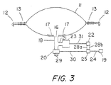
- the first preferred embodiment of the present invention is shown in figures 3 and 4. It includes a bypass valve 20 with a port 29.
- the valve 20 is attached via a fluid connector 18 to the gas inlet 16 and reinforcement 17.
- the bypass valve 20 is also attached via fluid connector 21 to a conventional gas generator 23.
- Bypass valve 20 is electrically connected to signal processor 25 via wire 30.
- the signal processor 25 is electrically connected to the seat belt usage sensor 19 via wire 24. Whenever the occupant engages his/her seat belt, the seat belt usage sensor 19 sends one type of signal via wire 24 to the signal processor 25 which then sends a signal via wire 30 that causes the valve 20 to open. Whenever the occupant disengages his/her seat belt, the seat belt usage sensor 19 sends a different signal via wire 24 to the signal processor 25 which signals the bypass valve 20 to close via wire 30.
- the signal processor 25 is also electrically connected to the crash sensor 22 via wires 28a and 28b.
- the crash sensor 22 detects changes in acceleration over a set time frame.
- a crash is defined as a change of acceleration over a time frame that surpasses or is greater than a set change of acceleration over a set time frame, known as a speed threshold.
- the crash sensor 22 of the present invention is sensitive and responsive to two crash speed thresholds: a moderate threshold when the crash speed is greater than 19.3 km/h and a severe threshold when the crash speed is greater than 32.2 km/h.
- the sensor 22 identifies the crash speed threshold and relays that information via wires 28a and 28b to the signal processor 25.
- the crash sensor 22 is also electrically connected via wire 31 to a conventional gas generator 23. When the sensor 22 detects a crash, it simultaneously sends a signal via wire 31 to the gas generator 23 which initiates gas generation and to the signal processor 25 via wires 28a and 28b.
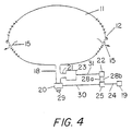
- the signal processor 25 evaluates the latest input from the seat belt usage sensor 19 and the input from the crash sensor 22. Via wire 30, the signal processor 25 either sends no signal, leaving the bypass valve 20 either fully open or fully closed. or it sends a signal that will partially open or partially close the bypass valve 30, depending on the belted condition of the occupant and the crash speed threshold. If the crash speed is moderate and the occupant is belted, the signal processor 25 sends no signal to the bypass valve 20, allowing it to remain fully open.
- the signal processor 25 sends a signal that causes the bypass valve 20 to be partially open by moving from a fully closed position or from a fully open position to a partially open position. If the crash speed is severe and the occupant is unbelted, the signal processor 25 sends no signal to the bypass valve 20, allowing it to remain fully closed.
- FIG. 5 and 6 Another preferred inflation system of the present invention is shown in Figures 5 and 6. It comprises crash and seat belt usage sensors, 22 and 19 respectively; a signal processor 25; and two conventional air bag gas generators 26a and 26b.
- the two gas generators 26a and 26b have different outputs, preferably approximately 40 percent and 60 percent of total, so that the small central volume can be inflated to soft or hard conditions and so that together the two generators 26a and 26b will produce enough gas to fully inflate the large inflatable volume of air bag 11.
- gas generator 26a is the larger generator
- gas generator 26b is the smaller generator.
- the crash sensor 22 is electrically connected to the signal processor 25 via wires 28a and 28b.
- the seat belt usage sensor 19 is electrically connected to the processor 25 via wire 24.
- the signal processor 25 is electrically connected to gas generators 26a and 26b via wires 33 and 34, respectively.
- the generators 26a and 26b are fluidly connected via fluid connector 27 to the air bag gas inlet 16 and reinforcement 17.
- the crash sensor 22, seat belt usage sensor 19, and signal processor 25, and their attaching wires function as described in the description of the above inflation system with the following exception.
- the signal processor 25 evaluates the inputs from the seat belt usage sensor 19 and crash sensor 22, and sends a signal to one or both of the gas generators 26a and 26b that initiates inflation. These inputs define the specific circumstances of the crash in terms of crash speed threshold and belted condition of the occupant. If the occupant is belted and the crash speed threshold is moderate, the signal processor 25 will signal the smaller gas generator 26b to initiate inflation.
- the signal processor 25 will signal the larger gas generator 26a to initiate inflation. If the occupant is unbelted and the crash speed threshold is severe, the processor 25 will signal both gas generators 26a and 26b to initiate inflation. Only in the latter situation will the gas break the breakaway stitching 13 and inflate the air bag's large inflatable volume.
- a first alternative embodiment is an air bag system that uses only seat belt usage as a discriminator, instead of both seat belt usage and crash speed threshold, is an alternate, low-cost embodiment of the present invention which would result in a low aggressivity air bag being deployed 75 out of 100 crash situations.
- a second alternative embodiment includes, in addition to the crash speed sensor and the seat belt usage sensor, a sensor which responsive to the position of the seat. If the seat is in a forward position (as would be the case for a short. e . g ., 5' 1", driver), the air bag deployment would use low aggressivity.
- a third alternative embodiment includes, in addition to the crash speed sensor and the seat belt usage sensor, a sensor responsive to the weight of the occupant, and the air bag system could factor in the occupant weight in determining the size and aggressivity of the air bag deployment.
Description
- The present application claims the benefit of the filing date of U.S. Provisional Application Serial No. 60/019,172, filed on June 5, 1996.
- The present invention relates to an air bag system that protects an occupant of a motor vehicle in the event of a crash. More particularly, it relates to an air bag system that provides a variable-size inflatable volume and a variable-output gas supply to produce optimal protection for the occupant regardless of whether he/she is wearing a seat belt and regardless of whether the crash speed is moderate or high.
- U.S. Federal Government safety regulations (Federal Motor Vehicle Safety Standard (FMVSS) 208) require that motor vehicle air hags protect unbelted front seat occupants in frontal barrier crashes where the vehicle is traveling at 48.3 km/h at impact. In order to do so, air bags must be relatively large, hard, and inflate rapidly. Collectively these characteristics describe an air bag that is referred to herein as an aggressive air bag. Although required by U.S. law, on some occasions, aggressive air bags can cause serious or even fatal injuries.
- This is all the more unfortunate because the U.S. government's own National Accident Statistic Study (NASS) shows that 98 percent of accidents causing air bag deployment occur at crash speeds at 48.3 km/h or below. (NASS is an ongoing statistical study of vehicle accidents conducted by the National Highway Traffic Safety Administration (NHTSA) of the U.S. Department of Transportation.) Furthermore, the study shows 80 percent of air bag deployments occur below 32.2 km/h. In addition, it points out that approximately 75 percent of front seat occupants now wear seat belts. Thus, only 0.5%, of the population (assuming that only 25% of the crash victims for accidents occurring at crash speeds of 48.3 km/h are not wearing seat belts) actually need an air bag that complies with the current government standard. Everyone else is being subjected unnecessarily to an aggressive air bag deployment.
- The air bag system that is installed in most of the vehicles currently sold in the United States does not distinguish between, or accommodate, the different protection needs of the occupant who is wearing a seat belt and one who is not. Instead, because of government safety standards, it is constructed purposefully to protect the unrestrained occupant in a severe crash from hitting the car interior by aggressively deploying a large air bag at a high inflation rate.
- An aggressive air bag can protect the occupant from hitting a structural part of the vehicle's interior. However, to do so he/she will very likely be struck by the air bag, and the potential for abrasions or more serious injuries is high. If restrained with a seat belt. the occupant is less at risk but often is still forcibly struck by the deploying bag. If unrestrained, the occupant travels faster and more forward before being struck by the deploying bag and experiences even greater harmful effects of deployment forces.
- Various means have been devised to attempt to overcome the potential hazards associated with the use of large, high aggressivity air bags. Some of these devices are as follows:
- U.S. Pat. No. 3,879,056 discloses an air bag with a belt-like restraining member that limits the extent of deployment When the occupant impacts the air bag, the restraining member breaks, which reduces the bag's air pressure and the rebounding force imparted to the occupant.
- U.S. Pat. No. 3,990,726 discloses an air bag with a seam that opens when the occupant hits the air bag, thus lowering bag pressure and rebounding force.
- U.S. Pat. No. 5,240,283 discloses an air bag with attached auxiliary bags which inflate with gas that is forced into them from the primary bag when the occupant strikes the primary bag.
- U.S. Pat. No. 5,282,646 discloses an air bag with a valve that controls inflation of two internal chambers. The chambers communicate via two openings. The first is always open and permits immediate flow of inflation gas from the first chamber, which is coupled to the inflator, to the second chamber. which is nearer the occupant. The other opening has a mesh covering and is normally closed by a flap that is also attached to the occupant-contacting wall. As the second chamber expands via inflation through the first opening, the occupant-contacting wall moves toward the occupant. When this wall reaches a predetermined expansion, the wall pulls the valve flap open and exposes the second opening. The air bag continues to inflate to its final volume; that is, to the extent the occupant-contacting wall can move toward the occupant.
- All of the above patents relate to air bags that can significantly change volume upon occupant loading but which have a fixed-volume gas generator supply. Because of their fixed-volume gas supply, these air bags can either adequately inflate the first volume or the bag's largest volume, but not both. If the gas in an air bag of this type of system adequately inflates the first volume and, upon occupant loading, presents a larger volume, the air bag will behave as if the first volume ruptured which would leave the occupant effectively unrestrained. Hence an air bag system constructed in this manner could only open in such a way that the gas would vent into the larger volume upon occupant impact at a rate equivalent to that of typical vented air bag designs in order to be an effective restraint. To be effective, a single gas generator air bag system can have only a single-volume air bag. Of course, if small changes in volume were allowed, a single gas generator could be used, but these small changes could never be used to accommodate differences in the effect of occupant loading that occur in belted versus unbelted occupant or moderate-speed crash versus high-speed crash situations. The above-cited patents pertain to what are hereinafter referred to as variable-volume, fixed-inflation designs.
- US Pat. No. 5,074,583 discloses a passenger-side air bag system including a seating condition sensor that detects the temperature of the passenger compartment and seating condition of a passenger with respect to seat position, reclining angle, passenger size, passenger posture, and seat belt usage. In accordance with the sensed seating condition, a control unit determines the timing of the inflation, gas pressure in the air bag, quantity of gas in the air bag, and the position of the air bag in relation to the occupant. This system has the drawbacks of being an extraordinarily heavy, complex, and costly system.
- US Pat No. 5,411,289 discloses an air bag system with a multiple-level gas generation source that inflates the air bag with a selected level of gas. The gas level and inflation sequence times are controlled by an electronic control unit which is responsive to attached temperature, seat belt, and acceleration sensors.
- The two patented systems cited immediately above provide varying gas generator output; however, there is no provision for varying air bag volume. Although they provide some adjustment in aggressivity, they are not designed to cover vast differences in required protection as occur, for instance, with a 19.8 km/h crash speed with belted occupant versus a 48.3 km/h crash speed with unbelted occupant. The above-cited patents pertain to what are hereinafter referred to as fixed-volume, variable-inflation designs.
- Deployment of an air bag having a first and second volume in response to a crash detector such that the volume of inflation is selected in response to the output of the crash detector is disclosed by DE 2944319.
- Document DE-A-2944319 discloses an air bag system comprising an air bag partitioned into separate sections by at least one releasable partition, said at least one releasable partition providing at least a first smaller volume and a second larger volume; an inflation system for inflating said air bag to either the first or the second volume, by using a variable amount of inflating gas such that the air bag is inflated to the first smaller volume when a first smaller amount of inflating gas is selected, and to the second larger volume when a second larger amount of inflating gas is selected, said second larger amount of inflating gas providing sufficient pressure in the air bag such that the releasable partition is released and the air bag inflates to the larger second volume; and a crash sensor.
- Further it discloses at least implicitly a method for inflating an air bag in a vehicle having an air bag system comprising an air bag partitioned into a plurality of sections by at least one releasable partition, a crash sensor, and a gas generating system for inflating the air bag with a plurality of amounts of inflating gas.
- Further it discloses an air bag system comprising an air bag having at least a first volume and a second volume, wherein said first volume is defined by a first section of the air bag, wherein a second section of the air bag is separated from the first section by a breakaway material, and wherein the second volume is the sum of the volumes of the first section and the second section; an inflation system for inflating said air bag to either the first or the second volume, using at least a first, a second or a third amount of inflating gas; and a crash sensor system.
- Further it discloses an air bag system, comprising an air bag having at least a first volume defined by a first section of the air bag and a second volume defined by the sum of the first section of the air bag and a second section of the air bag, said first and second sections of the air bag being separated by a releasable partition; an inflation system for inflating said air bag to either the first or the second volume using a first, a second, or a third amount of inflating gas; and a crash speed sensor.
- In summary, all of the above-cited inventions attempt to address the problems associated with the large, high aggressivity air bag by varying degrees and means. However, an air bag system is needed that fully addresses those problems and provides optimum protection regardless of whether the occupant is wearing a seat belt and whether the crash speed is moderate or severe. Further, the needs should be met with an air bag system that is simple in construction, economical to install, and compatible with existing equipment.
- The present invention is a variable-volume, variable-inflation air bag system for protecting a vehicle occupant in the event of a crash. It provides an air bag restraint system which, in terms of aggressivity, responds in accordance with the crash conditions in order to provide optimum occupant protection. The system responds in this manner through the use of an air bag that can inflate to two different volumes and gas generator source(s) that can provide at least two levels of inflation. The "normal" FMVSS 208 air bag will be deployed only as needed which is 5 percent of the time, as shown below.
- Injuries that occur as a result of aggressive air bag deployment can be nearly eliminated by this air bag system. It uses two discriminators to determine the nature of deployment: seat belt usage and crash speed threshold. Using figures derived from the above-cited study, the following crash population matrix shows the percentage of crashes that occur with respect to a speed threshold greater than 19.3 km/h and a threshold greater than 32.2 km/h for belted and unbelted occupants.
Seat belt engaged? Speed threshold >19.3 km/h, but ≤ 32.2 km/h > 32.2 km/h Yes 60% 15% No 20% 5% - The air bag is made of impermeable material suitable for air bag usage, which is well known in the art. Its large volume size is typical of air bags designed for protecting unrestrained occupants and sold in the U.S. That is, the air bag for driver-side use has an uninflated diameter of approximately 686 to 762 mm inches and holds approximately 60 to 80 liters of inflation gas in its full inflation mode. The air bag comprises front and rear panels that are joined along their peripheral edges by a means that creates a high-strength seam. High-strength stitching is the preferred means: however, the panels can also be woven, glued, or welded using high-frequency welding. The rear panel has a centrally located opening that is reinforced and is adapted for attachment to an inflation system.
- The air bag of the present invention is partitioned with a releasable means of attachment, such as an expanse of breakaway stitching. that is applied along the inner periphery of the air bag. This partitioning provides a separate inflatable area in the central portion of the air bag that has an inflated volume that is approximately 50 percent smaller than the inflated volume of the entire air bag. The provision of this smaller volume and the releasable partitioning, together with variable gas generation, is key to the invention's low aggressivity and its ability to protect the occupant in a range of crash circumstances. For the purpose of clarity, the central inflatable portion of the invention is referred herein as the small inflated or inflatable volume, and the entire inflatable area of the invention is referred herein as the large inflated or inflatable volume.
- Breakaway stitching is the preferred means to partition the air bag. However, other releasable means including weaving, gluing, high-frequency welding, hook and loop fastening, snaps, tongue and groove fastening, and tear fabric can be used and, additionally, pleats can be incorporated. For the purpose of clarity, the releasable means is identified hereinafter as breakaway stitching.
- Two preferred embodiments of the present invention are presented herein. The components and arrangements of both embodiments enable the air bag to deploy in a manner such that it provides the benefits of variable-size inflatable volume as well as variable gas supply. The following matrix, which incorporates figures from the above-cited study, defines the possible air bag deployments for the present invention which employs seat belt usage and crash speed threshold as discriminators.
Seat belt engaged? Speed threshold >19.3 km/h, but ≤ 32.2 km/h >32.2 km/h Yes Small Bag
40% gg
(accounts for 60% of crashes)Small Bag
60% gg
(accounts for 15% of crashes)No Small Bag
60% gg
(accounts for 20% of crashes)Large Bag
100% gg
(accounts for 5% of crashes)Note: The % gg refers to the percent of total inflation gas available that is generated as a result of gas generator selection or gas generator selection with open bypass. - A first preferred embodiment of the present invention includes a bypass valve, gas generator. seat belt usage sensor, crash sensor, and signal processor. The gas generator can produce enough gas to inflate the large inflatable volume of the air bag. However, inputs from the seat belt usage sensor and crash sensor actually determine the rate and amount of inflation gas that flows into the air bag. This system operates as described below.
- Anytime the occupant engages the seat belt, the seat belt usage sensor sends a signal to the signal processor which sends a signal to the bypass valve to open. Conversely, anytime the occupant disengages the seat belt, the seat belt sensor sends a signal to the signal processor that signals the valve to close. In the event of a crash, which is generally identified by the crash detector as a change in acceleration over a set time frame that exceeds a specific threshold, the crash detector sends a signal to the gas generator that initiates gas generation. At the same time, the crash detector sends a signal(s) to the signal processor that identifies the crash severity, i.e., that indicates the speed at which the crash occurred or that indicates whether the crash occurred at, above or below several speed thresholds. The speed indication may also be obtained from a separate sensor, such as the vehicle's speedometer. The signal processor may also be monitoring the speed of the vehicle, e.g., using input from the vehicle's speedometer system, such that it continually updates a register containing the vehicle speed. The signal processor evaluates the input from the crash detector (and, if necessary, from a separate speed indicator), and the latest input from the seat belt usage sensor. The processor response depends on the specific crash event as described below.
- In the event that the crash speed is greater than 19.3 km/h but below 33.8 km/h, herein termed moderate, and the occupant is belted, the signal processor sends no signal to the bypass valve, allowing it to remain fully open. Gas flows simultaneously out through the bypass valve and into the central portion of the air bag, inflating its small volume. Approximately 40 percent of the gas generated by the generator flows into the air bag and 60 percent flows out through the bypass valve. The inflated portion of the air bag is relatively small. Thus, in this situation, which describes 60 percent of all crashes, according to the above-cited study, it is unlikely that the deploying air bag will impact the occupant or that the occupant will load the air bag to any significant degree. However, should overload occur, gas will vent from the air bag out through the bypass valve port.
- In the event that the crash speed is greater than 32.2 km/h, herein termed severe, and the occupant is belted or the crash speed is below 33.8 km/h but greater than 19.3 km/h and the occupant is not belted, the signal processor sends a signal that causes the bypass valve to be partially open. In these crash situations, with encompass 35 percent of all crashes, according to the above-cited study, approximately 60 percent of the gas generated flows into the air bag and 40 percent flows out through the bypass valve.
- Inflation gas that flows out through the bypass valve is discharged outside the occupant compartment. It may, for example, be discharged through the fire wall into the engine bay. An open or partially open bypass valve limits the pressure and quantity of gas flowing into the air bag. This prevents the breakaway stitching from failing during inflation and allows only the small inflatable volume of the air bag to inflate.
- In the event that the crash speed is greater than 32.2 km/h and the occupant is unbelted, the signal processor sends no signal to the bypass valve. The valve remains closed and, of course, no gas bypasses. Instead. 100 percent of the gas generated flows into the central portion of the air bag, breaks the breakaway stitching, and inflates the air bag's large inflatable volume. When the occupant impacts the air bag, gas vents through openings that are located outward of the breakaway stitching.
- A second preferred embodiment of the present invention comprises two gas generators (or a dual-level gas generator), a crash sensor, seat belt usage sensor, and a signal processor. The following description assumes that the two gas generators have different outputs, preferably approximately 40 percent and 60 percent of the total output, so that the small central volume can be inflated to soft or hard conditions and so that together the two generators will produce enough gas to fully inflate the large inflatable volume.
- Anytime the occupant engages or disengages the seat belt, the seat belt sensor sends a signal to the signal processor. In the event of a crash, the crash detector sends a signal(s) to the signal processor that identifies the crash severity. The signal processor evaluates the input from the crash detector and the latest input from the seat belt usage sensor. The processor response depends on the specific crash event as described below.
- If the occupant is belted and the crash speed threshold is moderate, the signal processor will signal the smaller gas generator to initiate inflation. If the occupant is belted and the crash speed threshold is severe, or if the occupant is unbelted and the crash speed threshold is moderate, the signal processor will signal the larger gas generator to initiate inflation. If the occupant is unbelted and the crash speed threshold is severe, the processor will signal both gas generators to initiate inflation. Only when both gas generators are activated will the gas break the breakaway stitching and inflate the air bag's large inflatable volume
- The most distinguishing features and advantages of the invention are as follows. It provides a variable-size inflatable volume and a variable-output gas generation system to correctly accommodate the different protection needs of the occupant who is wearing a seat belt and the one who is not in both moderate and severe crashes. The use of breakaway stitching allows the capacity of the entire air bag to be always available to the occupant if needed depending on crash speed and seat belt usage. The air bag deploys in a low aggressive manner primarily because of two features: the partitioned inflatable central portion controlled by breakaway stitching and the use of a variable gas supply. The air bag either stops inflating at a small inflated volume, roughly 50 percent of the inflated volume of the entire air bag at a relatively low or high pressure, or it inflates to its large inflated volume in a controlled manner through the use of breakaway stitching. The small inflated volume displays low aggressivity by virtue of size and gas generator output. The breakaway stitching minimizes the air bag's aggressivity by decreasing the rapidity and limiting the forcefulness of the deployment when the large inflatable volume is inflating. The same factors that minimize the aggressivity also limit the rebound force that the air bag can impart to the occupant. Low aggressivity and low rebound force result in fewer injuries related to air bag deployment.
- The unvented construction of the smaller volume bag, which accident statistics show will be the deployed restraint with the use of the present invention 95 percent of the time, provides additional advantages. It eliminates air contamination of the vehicle's interior due to the release of inflation gas. This makes it especially practical for use in cases where changes in air quality or pressure can be critical. It also provides protection to the occupant in vehicles with small interiors in which the vented "smoke" of a gas generator could cause an egress problem.
- Accordingly, it is an object of the present invention to provide optimal protection for a vehicle occupant regardless of whether he/she is wearing a seat belt or the crash speed is moderate or severe.
- Another object of the present invention is to provide a protective vehicle air bag system that minimizes the kinetic energy imparted to the occupant during all deployment situations.
- Another object of the present invention is to provide a protective vehicle air bag system that minimizes the rebound energy imparted to the occupant upon impacting the air bag in the majority of deployment situations.
- Another object of the present invention is to provide a non-venting air bag for protecting the occupant of a motor vehicle in the majority of crash situations wherein a change in air quality and/or air pressure from the norm is particularly undesirable.
- Another object of the present invention is to provide an air bag system that is reliable in operation.
- Another object of the present invention is to provide an air bag system that is simple to manufacture.
- Another object of the present invention is to provide an air bag system that is economical to manufacture.
- Another object of the present invention is to provide an air bag that is lightweight relative to other air bags.
- Another object of the present invention to provide an air bag system that is compatible with existing vehicle equipment.
-
- Figure 1 is a schematic diagram of the front view of the front panel of an uninflated driver-side air bag of the present invention.
- Figure 2 is a schematic diagram of the back view of the rear panel of an uninflated driver-side air bag of the present invention.
- Figure 3 is a schematic diagram of the present invention showing the small volume of the air bag inflated of the first preferred embodiment of the present invention.
- Figure 4 is a schematic diagram of the top section view of the present invention showing the large volume of the air bag of the first preferred embodiment of the present invention
- Figure 5 is a schematic diagram of the top section view of the present invention showing the small volume of the air bag inflated of the second preferred embodiment of the present invention
- Figure 6 is a schematic diagram of the top section view of the present invention showing the large volume of the air bag inflated of the second preferred embodiment of the present invention
-
- The preferred embodiment of the uninflated driver's-side air bag of the present invention is shown in figures 1 and 2. Figures 3-4 and 5-6 show the present invention with the small air bag volume inflated and the large air bag volume inflated for an inflation system that employs a bypass valve (Figures 3-4) and one that employs two gas generators (Figures 5-6). These figures show a round configuration for driver-side use. However, the air bag of the present invention may utilize any functional shape including oblong, square, and rectangular for driver-side or passenger-side use. Although only front and back panels are shown in detail and described herein, the air bag of the present invention can also have side panels. Regardless of the configuration, the overall size of the air bag of the present invention is typical of air bags manufactured today. For example, for driver-side use, the present invention in a round configuration, such as shown in Figures 1-2, has a flat. uninflated diameter of approximately 686 to 762 mm. The air bag material is also conventional. For example, the material of air bag 11 can be a woven nylon fabric of 420 denier coated inside with neoprene.
- Figures 1 and 2 show the
air bag front 10 and rear 14 panels, respectively. These panels are joined peripherally such that a seam is created along the outside edge. Alternately, the panels can be joined such that the seam is inside the air bag. Preferably, the panels are joined by high-strength stitching 12. However, other means of attachment such as adhesion and high-frequency welding may also be used.Stitching 12 is comprised of approximately two closely set lines of straight horizontally-applied stitches that can withstand pressure of at least 1.378952 bar before breaking. Other high-strength stitching patterns can be applied. Preferably, the thread ofstitching 12 is 420 denier nylon thread, and the stitches are applied in the range of 7 to 10 per 25.4 mm. -
Breakaway stitching 13 defines a central area within the air bag 11 and can withstand a pressure of approximately 0.4826332 bar before breaking. It is made preferably of 0.816kg breaking-strength nylon thread with stitches applied in a range of 10 to 18 per 25.4mm. The small inflatable volume is defined by the expanse of unstitched area that is bordered by the innermost breakaway stitching 13 line. This volume is approximately 50 percent of the inflated volume of the entire air bag 11. - Figure 2 shows vent holes 15 located on the air bag
rear panel 14 within the unstitched expanse betweenstitching 12 and breakaway stitching 13. Together, these vent holes provide approximately one to two square inches of vent area. Therear panel 14 also has aninflation gas inlet 16. Surrounding thegas inlet 16 is areinforcement 17 that is adapted to couple to the inflation system. The exact configuration of theinlet 16 andreinforcement 17 is dependent on the configuration of theinflation system connector 18 that is used. - The first preferred embodiment of the present invention is shown in figures 3 and 4. It includes a
bypass valve 20 with aport 29. Thevalve 20 is attached via afluid connector 18 to thegas inlet 16 andreinforcement 17. Thebypass valve 20 is also attached viafluid connector 21 to aconventional gas generator 23.Bypass valve 20 is electrically connected to signalprocessor 25 viawire 30. Thesignal processor 25 is electrically connected to the seatbelt usage sensor 19 viawire 24. Whenever the occupant engages his/her seat belt, the seatbelt usage sensor 19 sends one type of signal viawire 24 to thesignal processor 25 which then sends a signal viawire 30 that causes thevalve 20 to open. Whenever the occupant disengages his/her seat belt, the seatbelt usage sensor 19 sends a different signal viawire 24 to thesignal processor 25 which signals thebypass valve 20 to close viawire 30. - The
signal processor 25 is also electrically connected to thecrash sensor 22 viawires crash sensor 22 detects changes in acceleration over a set time frame. A crash is defined as a change of acceleration over a time frame that surpasses or is greater than a set change of acceleration over a set time frame, known as a speed threshold. Thecrash sensor 22 of the present invention is sensitive and responsive to two crash speed thresholds: a moderate threshold when the crash speed is greater than 19.3 km/h and a severe threshold when the crash speed is greater than 32.2 km/h. Thesensor 22 identifies the crash speed threshold and relays that information viawires signal processor 25. - If the crash speed threshold is moderate,
only wire 28a will send a signal toprocessor 25. If the crash speed threshold is severe, bothwires processor 25. Thecrash sensor 22 is also electrically connected viawire 31 to aconventional gas generator 23. When thesensor 22 detects a crash, it simultaneously sends a signal viawire 31 to thegas generator 23 which initiates gas generation and to thesignal processor 25 viawires - The
signal processor 25 evaluates the latest input from the seatbelt usage sensor 19 and the input from thecrash sensor 22. Viawire 30, thesignal processor 25 either sends no signal, leaving thebypass valve 20 either fully open or fully closed. or it sends a signal that will partially open or partially close thebypass valve 30, depending on the belted condition of the occupant and the crash speed threshold. If the crash speed is moderate and the occupant is belted, thesignal processor 25 sends no signal to thebypass valve 20, allowing it to remain fully open. If the crash speed is severe and the occupant is belted or the crash speed is moderate and the occupant is not belted, thesignal processor 25 sends a signal that causes thebypass valve 20 to be partially open by moving from a fully closed position or from a fully open position to a partially open position. If the crash speed is severe and the occupant is unbelted, thesignal processor 25 sends no signal to thebypass valve 20, allowing it to remain fully closed. - Another preferred inflation system of the present invention is shown in Figures 5 and 6. It comprises crash and seat belt usage sensors, 22 and 19 respectively; a
signal processor 25; and two conventional airbag gas generators gas generators generators gas generator 26a is the larger generator, andgas generator 26b is the smaller generator. Thecrash sensor 22 is electrically connected to thesignal processor 25 viawires belt usage sensor 19 is electrically connected to theprocessor 25 viawire 24. Thesignal processor 25 is electrically connected togas generators wires generators fluid connector 27 to the airbag gas inlet 16 andreinforcement 17. - The
crash sensor 22, seatbelt usage sensor 19, andsignal processor 25, and their attaching wires function as described in the description of the above inflation system with the following exception. In the event of a crash, thesignal processor 25 evaluates the inputs from the seatbelt usage sensor 19 andcrash sensor 22, and sends a signal to one or both of thegas generators signal processor 25 will signal thesmaller gas generator 26b to initiate inflation. If the occupant is belted and the crash speed threshold is severe, or if the occupant is unbelted and the crash speed threshold is moderate, thesignal processor 25 will signal thelarger gas generator 26a to initiate inflation. If the occupant is unbelted and the crash speed threshold is severe, theprocessor 25 will signal bothgas generators - The present invention can also be implemented in alternative embodiments to the embodiments described above. A first alternative embodiment is an air bag system that uses only seat belt usage as a discriminator, instead of both seat belt usage and crash speed threshold, is an alternate, low-cost embodiment of the present invention which would result in a low aggressivity air bag being deployed 75 out of 100 crash situations. A second alternative embodiment includes, in addition to the crash speed sensor and the seat belt usage sensor, a sensor which responsive to the position of the seat. If the seat is in a forward position (as would be the case for a short. e.g., 5' 1", driver), the air bag deployment would use low aggressivity. A third alternative embodiment includes, in addition to the crash speed sensor and the seat belt usage sensor, a sensor responsive to the weight of the occupant, and the air bag system could factor in the occupant weight in determining the size and aggressivity of the air bag deployment.
- The foregoing disclosure of the present invention has been presented for the purposes of illustration and description. It is not intended to be exhaustive or to limit the invention to the precise forms disclosed. In particular, the present invention can be used in ground, sea, or air vehicles in addition to automobiles. For example, the present invention may be used in trains, trucks, buses, vans, boats, ships, and aircraft. Many variations and modifications of the invention described herein will be obvious to one of ordinary skill in the art in light of the above disclosure, in addition to the modifications described above.
- The invention is defined by the appended claims.
Claims (44)
- An air bag system comprising:wherein the signal processor (25) selects one of said at least first smaller and second larger volumes and the amount of inflating gas as follows:(a) a seat belt comprising a seat belt usage sensor (19);(b) an air bag (11) partitioned into separate sections by at least one releasable partition (13), said at least one releasable partition (13) providing at least a first smaller volume and a second larger volume;(c) an inflation system for inflating said air bag (11) to either the first smaller or the second larger volume, by using a variable amount of inflating gas such that the air bag (11) is inflated to the first smaller volume when a first smaller amount of inflating gas is selected, and to the second larger volume when a second larger amount of inflating gas is selected, said second larger amount of inflating gas providing sufficient pressure in the air bag (11) such that the at least one releasable partition (13) is released and the air bag (11) inflates to the second larger volume;(d) a crash sensor (22) responsive to at least a first crash speed threshold and a second crash speed threshold; and(e) a signal processor (25) electrically connected to the crash sensor (22) and the seat belt usage sensor (19),(i) if the seat belt is engaged, and the crash sensor (22) indicates that the crash speed is above the first crash speed threshold but below the second crash speed threshold, the first smaller amount of inflating gas is selected;(ii) if the seat belt is not engaged and the crash sensor (22) indicates that the crash speed is above the second crash speed threshold, the second larger amount of inflating gas is selected.
- The air bag system of claim 1, wherein a third intermediate amount of inflating gas may be selected by the signal processor (25), said third intermediate amount of inflating gas not providing sufficient pressure in the air bag (11) to release the at least one releasable partition (13), and wherein the third intermediate amount of inflating gas is selected in the event of a crash occurring at a crash speed above the first crash speed threshold and below the second crash speed threshold when the seat belt is not engaged.
- The air bag system of claim 2, wherein said third intermediate amount of inflating gas is selected in the event of a crash occurring above the second crash speed threshold when the seat belt is engaged.
- The air bag system of claim 2, wherein said air bag (11) comprises a first section and a second section separated by said at least one releasable partition (13), and wherein said second section has a volume larger than said first section.
- The air bag system of claim 3, wherein the first smaller amount of inflating gas is sufficient to inflate the air bag (11) to the first smaller volume at a first lower pressure and the third intermediate amount of inflating gas is sufficient to inflate the air bag (11) to the first smaller volume at a second higher pressure.
- The air bag system of claim 1, wherein said inflation system comprises:wherein the third intermediate amount of inflating gas does not provide sufficient pressure to release the at least one releasable partition (13), and(c)(i) a first gas generator (26a) electronically connected to said signal processor (25) for generating the first smaller amount of inflating gas; and(c)(ii) a second gas generator (26b) electronically connected to said signal processor (25) for generating a third intermediate amount of inflating gas, wherein the total amount of gas generated by the first and second gas generators (26a, 26b) is the second larger amount of inflating gas,
wherein said signal processor (25) transmits signals to said first and second gas generators (26a, 26b) to initiate the generation of inflating gas by said first gas generator (26a) only when the seat belt is engaged and the crash sensor (22) indicates that the crash speed is above the first crash speed threshold but below the second crash speed threshold and to initiate the generation of inflating gas by both said first gas generator (26a) and said second gas generator (26b) when the seat belt is not engaged and the crash speed is above the second crash speed threshold. - The air bag system of claim 6,
wherein said first smaller amount of inflating gas is sufficient to inflate said first smaller volume at said first lower pressure, said third intermediate amount of inflating gas is sufficient to inflate said first smaller volume at a second higher pressure, and wherein said second larger amount of inflating gas is sufficient to release the at least one releasable partition (13) and to fully inflate the air bag to said second larger volume. - The air bag system of claim 2, further comprising a seat position sensor electrically connected to the signal processor (25), wherein the signal processor (25) selects the first smaller amount of inflating gas or the third intermediate amount of inflating gas if the seat is in a forward position, even if the crash sensor (22) indicates that the crash speed is above the second crash speed threshold.
- A method for inflating an air bag in a vehicle having an air bag (11) system comprising
an air bag (11) partitioned into a plurality of sections by at least one releasable partition (13),
a crash sensor (22) responsive to a plurality of crash speed thresholds,
a seat belt usage sensor (19), a signal processor (25) electrically connected to the seat belt usage sensor (19) and to the crash sensor (22), and a
gas generating system electrically connected to the signal processor (25) for inflating the air bag (11) with a plurality of amount of inflating gas,
wherein the signal processor (25) carries out the following steps:wherein the second larger amount of inflating gas inflates the air bag (11) at such a pressure that the at least one releasable partition (13) is released, allowing the air bag (11) to inflate to a second larger volume.(a) monitoring the seat belt usage;(b) receiving signals from the crash sensor (22) indicating a crash and a crash speed threshold; and(c) inflating the air bag (11) to a volume determined by the seat belt usage and the crash speed threshold, using an amount of inflating gas determined by the seat belt usage and the crash speed threshold as follows:(i) if the seat belt is engaged, and the crash sensor (22) indicates that the crash speed is above the first crash speed threshold but below the second crash speed threshold, selecting the first smaller amount of inflating gas and inflating the air bag (11) to a first smaller volume at a first lower pressure;(ii) if the seat belt is not engaged and the crash sensor (22) indicates that the crash speed is above the second crash speed threshold, selecting the second larger amount of inflating gas, - The method of claim 9, further comprising the step of:selecting a third intermediate amount of inflating gas and inflating the air bag (11) to the first smaller volume at a second higher pressure if (i) the crash occurs at a crash speed above the second crash speed threshold and the seat belt is engaged or (ii) if the crash speed occurs above the first crash speed threshold but below the second crash speed threshold and the seat belt is not engaged.
- The method of claim 10, wherein said gas generating system has a plurality of gas generators (26a, 26b), wherein each gas generator (26a, 26b) can generate an amount of inflating gas, wherein the total amount of generating gas generated by said plurality of gas generators (26a, 26b) is sufficient to fully inflate the air bag (11).
- The method of claim 10, wherein said gas generating system has a plurality of generators (26a, 26b) comprising a first and a second gas generator (26a, 26b), and wherein said first gas generator (26a) has a gas generation capacity that is sufficient to fully inflate said first smaller volume of the air bag (11).
- The method of claim 12, wherein said second gas generator (26b) has a gas generation capacity that, when added to the amount of gas generated by the first gas generator (26a), is sufficient to fully inflate the air bag (11).
- The method of claim 9, wherein said air bag system comprises a bypass valve (20) electrically connected to said signal processor (25), wherein said bypass valve (20) is controlled by the signal processor (25) to select the amount of inflating gas that is used to inflate the air bag (11).
- The method of claim 14, wherein the bypass valve (20) comprises a fully open position, a partially open position, and a fully closed position, and wherein the signal processor (25) provides a signal to the bypass valve (20) which sets the bypass valve (20) to one of the fully open position, partially open position and fully closed position.
- An air bag system as claimed in any one of claims 1 to 8 wherein the inflation system comprises:a variable-output gas generator system (23) for inflating said air bag (11) to either the first smaller volume or the second larger volume, wherein the gas generator system (23) introduces one of a first, a second, and a third amount of inflating gas into the air bag (11);and wherein the signal processor (25) controls the inflation of the air bag (11) such that:(i) if the seat belt is engaged and the crash speed is above the first crash speed threshold and below the second crash speed threshold, the air bag (11) is inflated to the first smaller volume at a first lower pressure using the first amount of inflating gas,(ii) if the seat belt is engaged and the crash speed is above the second crash speed threshold, the air bag (11) is inflated to the first smaller volume at a second higher pressure using the second amount of inflating gas; and(iii)if the seat belt is not engaged, and the crash speed is above the first crash speed threshold and below the second crash speed threshold, the air bag (11) is inflated to the first smaller volume at the second higher pressure using the second amount of inflating gas; and(iv) if the seat belt is not engaged and the crash speed is above the second crash speed threshold, the air bag (11) is inflated to the second larger volume using the third amount of inflating gas.
- The air bag system of claim 16, wherein the variable-output gas generator system (23) comprises a bypass valve (20), fluidly connected to the air bag (11) and to a gas generator (23), having a fully open position, a partially open position, and a fully closed position, and wherein the signal processor (25) is electrically connected to the bypass valve (20) to control the position of the bypass valve (20) to provide the first, second or third amount of inflating gas.
- The air bag system of claim 17, wherein the signal processor (25) controls the bypass valve (20) to:introduce the first amount of inflating gas into the air bag (11) by setting the bypass valve (20) to the fully open position,introduce the second amount of inflating gas into the air bag (11) by setting the bypass valve (20) to the partially open position, andintroduce the third amount of inflating gas into the air bag (11) by setting the bypass valve (20) to the fully closed position.
- The air bag system of claim 16, wherein the variable-output gas generator system comprises a first gas generator (26a) electrically connected to the signal processor (25) capable of generating a first amount of inflating gas, and a second gas generator (26b) capable of generating a second amount of inflating gas,
wherein said signal processor (25) controls the first and second gas generators (26a, 26b) to produce the first, second and third amounts of inflating gas. - The air bag system of claim 16, wherein said first smaller volume and said second larger volume are defined by a first section and a second section of the air bag (11).
- The air bag system of claim 20, comprising breakaway material that resists breaking until said gas generating system inflates the first section of the air bag (11) at the first lower pressure using the first amount of inflating gas, inflates the first section of the air bag (11) at the second higher pressure using the second amount of inflating gas, and wherein said breakaway material (13) breaks away after the first section is fully inflated to allow inflation of the second section of the air bag (11) using the third amount of inflating gas.
- The air bag system of claim 20, wherein said breakaway material comprises breakaway stitching (13).
- The air bag system of claim 16, further comprising a seat position sensor, wherein the signal processor (25) also considers the seat position in determining whether to inflate the air bag (11) to the first smaller or to the second larger volume, and in determining whether to introduce the first amount, the second amount or the third amount of inflating gas into the air bag (11).
- The air bag system of claim 1 or 2, further comprising a sensor responsive to the weight on a seat, wherein the signal processor (25) also considers the weight on the seat in determining whether to inflate air bag (11) to the first smaller or to the second larger volume, and in determining whether to introduce the first amount, the second amount or the third amount of inflating gas into the air bag (11).
- An air bag system comprising:(a) a seat belt comprising a seat belt usage sensor (19);(b) an air bag (11) having at least a first volume and a second volume, wherein said first volume is defined by a first section of the air bag (11), wherein a second section of the air bag (11) is separated from the first section by a breakaway material (13), and wherein the second volume is the sum of the volumes of the first section and the second section;(c) an inflation system for inflating said air bag (11) to either the first or the second volume, using at least a first, a second or a third amount of inflating gas;(d) a crash sensor system (22) comprising a crash detector and a speed indicator; and(e) a signal processor (25) electrically connected to the crash sensor (22) and to the seat belt usage sensor (19), wherein the signal processor (25) initiates deployment of the air bag (11) upon receiving a signal from the crash detector indicating that a crash is occurring, and wherein the signal processor (25) selects one of said first and second volumes and the first, second or third amounts of inflating gas as follows:(i) if the seat belt is engaged and the crash speed is above the first crash speed threshold and below the second crash speed threshold, the air bag (11) is inflated to the first volume at a first lower pressure using the first amount of inflating gas,(ii) if the seat belt is engaged and the crash speed is above the second crash speed threshold, the air bag (11) is inflated to the first volume at a second higher pressure using the second amount of inflating gas;(iii) if the seat belt is not engaged, and the crash speed is above the first crash speed threshold and below the second crash speed threshold, the air bag (11) is inflated to the first volume at the second higher pressure using the second amount of inflating gas; and(iv) if the seat belt is not engaged and the crash speed is above the second crash speed threshold, the air bag (11) is inflated to the second volume using the third amount of inflating gas by breaking away the breakaway material (13) separating the first section from the second section.
- The air bag system of claim 25, wherein said air bag (11) comprises a plurality of sections, each of said sections having a volume that can be inflated by said inflation system.
- The air bag system of claim 26, further comprising breakaway material separating said plurality of sections that resists breaking until said inflation system fills one or more sections of the air bag (11).
- The air bag system of claim 26, wherein said first amount of inflating gas is sufficient to fill said first section at the first lower pressure, said second amount of inflating gas is sufficient to fill said first section at the second higher pressure, and said third amount of inflating gas is sufficient to completely fill said first and second sections.
- The air bag system of claim 4, 16 or 28, wherein said inflation system inflates said first section prior to inflating said second section.
- The air bag system of claim 29, wherein said breakaway material (13) breaks when said first section has been filled by said inflation system, thereafter allowing said inflation system to fill said second section.
- The air bag system of claim 5, 16, 20 or 30, wherein said first section is contained inside said second section.
- The air bag system of claim 1,16 or 25, further comprising a bypass valve (20) electrically connected to said signal processor (25), wherein said bypass valve (20) is controlled by the signal processor (25) to select the amount of inflating gas that is used to inflate the air bag (11).
- The air bag system of claim 16 or 32, wherein the bypass valve (20) comprises a fully open position, a partially open position, and a fully closed position, and wherein the signal processor (25) provides a signal to the bypass valve (20) which sets the bypass valve (20) to one of the fully open position, partially open position, and fully closed position.
- The air bag system of claim 32, wherein the bypass valve (20) comprises a fully open position, a partially open position, and a fully closed position, and wherein the signal processor (25) provides a signal to the bypass valve (20) which sets the bypass valve (20) to one of the fully open position, partially open position, and fully closed position to select the first amount of inflating gas, the second amount of inflating gas or the third amount of inflating gas, respectively.
- The air bag system of claim 25, wherein said inflation system comprises:wherein the third amount of inflating gas is the total of the first and second amounts of inflating gas, such that the third amount of inflating gas is generated by initiating inflation of both the first and second gas generators (26a, 26b), and(c)(i) a first gas generator (26a) electrically connected to said signal processor (25) for generating the first amount of inflating gas; and(c)(ii) a second gas generator (26b) electrically connected to said signal processor (25) for generating the second amount of inflating gas,
wherein said signal processor (25) transmits signals to said first and second gas generators (26a, 26b) to initiate the generation of inflating gas by said first and second gas generators (26a, 26b). - The air bag system of claim 35, wherein said air bag (11) comprises:said second amount of inflating gas is sufficient to inflate said first volume at the second higher pressure, and(b)(i) a first section having the first volume; and(b)(ii) a second section, wherein the second volume is the sum of the volumes of the first and second sections, and wherein said first amount of inflating gas is sufficient to inflate said first volume at the first lower pressure,
wherein said third amount of inflating gas is sufficient to fully inflate said second volume. - The air bag system of claim 25, further comprising a seat position sensor, wherein the signal processor (25) selects the first or second amounts of inflating gas if the seat is in a forward position, even if the crash detector indicates that the crash speed is above the second crash speed threshold.
- The air bag system of claim 2, further comprising a sensor responsive to the weight on a seat, wherein the signal processor (25) selects the first smaller amount of inflating gas or the third intermediate amount of inflating gas if the weight on the seat is below a predetermined limit, even if the crash sensor (22) indicates that the crash speed is above the second crash speed threshold.
- The air bag system of claim 25, further comprising a sensor responsive to the weight on a seat, wherein the signal processor (25) selects the first smaller amount of inflating gas or the third intermediate amount of inflating gas if the weight on the seat is below a predetermined limit, even if the crash detector indicates that the crash speed is above the second crash speed threshold.
- An air bag system, comprising:(a) an air bag (11) having at least a first volume defined by a first section of the air bag (11) and a second volume defined by the sum of the first section of the air bag (11) and a second section of the air bag (11), said first and second sections of the air bag (11) being separated by a releasable partition (13);(b) an inflation system for inflating said air bag (11) to either the first or the second volume using a first, a second, or a third amount of inflating gas;(c) a seat belt system comprising a seat belt usage sensor (19);(d) a seat position sensor;(e) a signal processor (25) coupled to said air bag (11), a crash speed sensor (22) and to said inflation system for inflating said air bag (11) when said signal processor (25) detects a crash as follows:(i) if the seat belt is engaged and the crash speed is above the first crash speed threshold and below the second crash speed threshold, the air bag (11) is inflated to the first volume at a first lower pressure using the first amount of inflating gas,(ii) if the seat belt is engaged and the crash speed is above the second crash speed threshold, the air bag (11) is inflated to the first volume at a second higher pressure using the second amount of inflating gas;(iii) if the seat belt is not engaged, and the crash speed is above the first crash speed threshold and below the second crash speed threshold, the air bag (11) is inflated to the first volume at the second higher pressure using the second amount of inflating gas;(iv) if the seat belt is not engaged and the crash speed is above the second crash speed threshold and the seat position sensor indicates that the seat is not in a forward position, the air bag (11) is inflated to the second volume using the third amount of inflating gas, wherein the third amount of inflating gas provides sufficient pressure to release the releasable partition (13) and to allow the inflating gas to enter the second section of the air bag (11); and(v) if the seat belt is not engaged and the crash speed is above the second crash speed threshold and the seat position sensor indicates that the seat is in a forward position, the air bag (11) is inflated to the first volume using the second amount of inflating gas.
- The air bag system of claim 40, wherein the first section of the air bag (11) is a central portion of the entire air bag (11), releasably partitioned from the remaining portion of the air bag (11).
- The air bag system of claim 41, wherein the first section of the air bag (11) is releasably attached to the air bag (11) using breakaway stitching (13).
- The air bag system of claim 41, wherein the air bag (11) has a circular cross-section, and the first section of the air bag (11) also has a circular cross-section.
- The air bag system of claim 43, wherein the center of the circular cross-section of the first section of the air bag (11) is approximately coincident with the center of the circular cross-section of the air bag (11).
Applications Claiming Priority (5)
| Application Number | Priority Date | Filing Date | Title |
|---|---|---|---|
| US1917296P | 1996-06-05 | 1996-06-05 | |
| US19172P | 1996-06-05 | ||
| US08/762,219 US5871231A (en) | 1996-06-05 | 1996-12-09 | Low aggressivity variable-volume variable-inflation air bag system |
| US762219 | 1996-12-09 | ||
| PCT/US1997/011614 WO1997046425A1 (en) | 1996-06-05 | 1997-06-05 | Low aggressivity variable-volume variable-inflation air bag system |
Publications (3)
| Publication Number | Publication Date |
|---|---|
| EP0901432A1 EP0901432A1 (en) | 1999-03-17 |
| EP0901432A4 EP0901432A4 (en) | 2000-11-15 |
| EP0901432B1 true EP0901432B1 (en) | 2005-02-09 |
Family
ID=26691943
Family Applications (1)
| Application Number | Title | Priority Date | Filing Date |
|---|---|---|---|
| EP97932464A Expired - Lifetime EP0901432B1 (en) | 1996-06-05 | 1997-06-05 | Low aggressivity variable-volume variable-inflation air bag system |
Country Status (7)
| Country | Link |
|---|---|
| US (1) | US5871231A (en) |
| EP (1) | EP0901432B1 (en) |
| JP (1) | JP3919819B2 (en) |
| AU (1) | AU3591897A (en) |
| DE (1) | DE69732484T8 (en) |
| ES (1) | ES2236818T3 (en) |
| WO (1) | WO1997046425A1 (en) |
Cited By (3)
| Publication number | Priority date | Publication date | Assignee | Title |
|---|---|---|---|---|
| KR20110119311A (en) * | 2010-04-27 | 2011-11-02 | 현대모비스 주식회사 | A passenger air-bag cushion |
| EP3031675A1 (en) * | 2014-12-12 | 2016-06-15 | Mosa Industrial Corporation | Dual stage hybrid inflator and method of triggering the same |
| US10604259B2 (en) | 2016-01-20 | 2020-03-31 | Amsafe, Inc. | Occupant restraint systems having extending restraints, and associated systems and methods |
Families Citing this family (54)
| Publication number | Priority date | Publication date | Assignee | Title |
|---|---|---|---|---|
| JP4079479B2 (en) * | 1997-06-13 | 2008-04-23 | タカタ株式会社 | Vehicle seat device and airbag device |
| JP3577208B2 (en) * | 1997-12-09 | 2004-10-13 | トヨタ自動車株式会社 | Passenger airbag device |
| JP3296279B2 (en) * | 1997-12-10 | 2002-06-24 | 三菱自動車工業株式会社 | Vehicle airbag device |
| DE29813082U1 (en) * | 1998-07-22 | 1998-11-19 | Trw Repa Gmbh | Airbag restraint system |
| JP3694727B2 (en) * | 1998-07-27 | 2005-09-14 | 日産自動車株式会社 | Automotive safety devices |
| DE19903361A1 (en) * | 1999-01-28 | 2000-08-03 | Breed Automotive Tech | Airbag manufacturing method and airbag |
| DE29907618U1 (en) * | 1999-04-29 | 1999-09-16 | Trw Repa Gmbh | Airbag restraint system |
| DE29916700U1 (en) * | 1999-09-22 | 2000-02-03 | Trw Repa Gmbh | Gas bag |
| EP1504970B1 (en) * | 1999-11-12 | 2015-03-18 | Autoliv Development AB | Variable profile air bag restraint |
| US6581961B1 (en) * | 1999-12-17 | 2003-06-24 | Trw Vehicle Safety Systems Inc. | Deactivation of second stage of air bag inflator |
| JP4356191B2 (en) * | 2000-04-25 | 2009-11-04 | タカタ株式会社 | Airbag device |
| US6918611B1 (en) | 2000-09-28 | 2005-07-19 | Delphi Technologies, Inc. | System and method for controlling an inflatable cushion |
| DE10116926B4 (en) * | 2001-04-05 | 2005-06-16 | Daimlerchrysler Ag | Method for controlling a gas generator for an airbag in a motor vehicle |
| US6517108B1 (en) | 2002-01-02 | 2003-02-11 | Ford Global Technologies, Inc. | Pyrotechnic air bag stitch vent |
| US6736425B2 (en) | 2002-01-28 | 2004-05-18 | Ford Global Technologies, Llc | System for venting an air bag module |
| US6802528B2 (en) | 2002-04-05 | 2004-10-12 | Ford Global Technologies, Llc | Air bag cushion energy diverter |
| US6746045B2 (en) | 2002-04-05 | 2004-06-08 | Ford Global Technologies, Llc | Air bag inflator gas venting system |
| US6986529B2 (en) | 2002-04-23 | 2006-01-17 | Trw Vehicle Safety Systems Inc. | Air bag module with vent |
| JP2004082762A (en) * | 2002-08-22 | 2004-03-18 | Nippon Plast Co Ltd | Airbag |
| DE10320120A1 (en) * | 2003-05-06 | 2004-12-09 | Johann Berger | Inflatable woven air bag or air belt |
| JP3914221B2 (en) * | 2003-12-16 | 2007-05-16 | 本田技研工業株式会社 | Airbag device |
| US7401811B2 (en) * | 2003-09-10 | 2008-07-22 | Honda Motor Co., Ltd. | Airbag device |
| GB2412353A (en) * | 2004-03-24 | 2005-09-28 | Autoliv Dev | Air bag having a tear seam |
| US7232001B2 (en) * | 2004-08-24 | 2007-06-19 | Sam Hakki | Collision air bag and flotation system |
| JP4896389B2 (en) * | 2004-11-02 | 2012-03-14 | カルソニックカンセイ株式会社 | Airbag deployment control device |
| DE102005024113A1 (en) | 2005-01-21 | 2006-08-10 | Trw Automotive Safety Systems Gmbh & Co. Kg | Airbag module |
| US7661708B2 (en) * | 2005-01-21 | 2010-02-16 | Trw Automotive Safety Systems Gmbh | Gas bag module |
| US20060202454A1 (en) * | 2005-03-08 | 2006-09-14 | Amnon Parizal | Airbag assembly and modulated airbag inflation process |
| DE102005011641B4 (en) * | 2005-03-14 | 2017-04-06 | Trw Automotive Gmbh | airbag |
| US7377548B2 (en) * | 2005-05-06 | 2008-05-27 | Tk Holdings Inc. | Adaptive depth airbag |
| EP1747949A3 (en) * | 2005-07-27 | 2007-03-07 | Mazda Motor Corporation | Steering wheel equiped with an airbag device |
| US20070170710A1 (en) | 2006-01-24 | 2007-07-26 | Benoit Bouquier | Venting systems for inflatable objects |
| JP4952077B2 (en) * | 2006-06-14 | 2012-06-13 | タカタ株式会社 | Air bag and air bag device |
| JP5007539B2 (en) * | 2006-09-01 | 2012-08-22 | タカタ株式会社 | Air bag and air bag device |
| DE202006017996U1 (en) * | 2006-11-22 | 2007-02-15 | Takata-Petri Ag | Airbag for a vehicle comprises sleeve sections each forming an airbag layer which are connected together forming the airbag sleeve and are separated from each other when the airbag is expanded |
| JP5049660B2 (en) * | 2007-06-11 | 2012-10-17 | 本田技研工業株式会社 | Airbag device |
| JP5251032B2 (en) | 2007-08-09 | 2013-07-31 | タカタ株式会社 | Air bag and air bag device |
| US8388019B2 (en) * | 2009-09-29 | 2013-03-05 | Tk Holdings Inc. | Airbag module |
| JP5418472B2 (en) * | 2010-02-26 | 2014-02-19 | 豊田合成株式会社 | Airbag device |
| JP5387479B2 (en) * | 2010-03-30 | 2014-01-15 | 豊田合成株式会社 | Airbag |
| US20110260436A1 (en) * | 2010-04-27 | 2011-10-27 | Park Hae Kwon | Passenger airbag apparatus |
| JP5629554B2 (en) | 2010-11-04 | 2014-11-19 | タカタ株式会社 | Air bag and air bag device |
| DE102010052412B4 (en) * | 2010-11-24 | 2017-11-16 | Daimler Ag | A method and apparatus for protecting a vehicle occupant in a vehicle seat of a vehicle |
| US8657333B2 (en) * | 2011-07-27 | 2014-02-25 | Autoliv Asp, Inc. | Inflator device with fuel-rich monolithic grain and oxidant-enhanced combustion |
| EP2604479B8 (en) | 2011-12-13 | 2014-12-17 | Airbus Helicopters | A device for protecting an individual sitting on a seat, a seat, and a vehicle |
| US8523220B1 (en) | 2012-03-19 | 2013-09-03 | Amsafe, Inc. | Structure mounted airbag assemblies and associated systems and methods |
| US9511866B2 (en) | 2012-03-19 | 2016-12-06 | Amsafe, Inc. | Structure mounted airbag assemblies and associated systems and methods |
| DE102013212771A1 (en) * | 2013-06-28 | 2014-12-31 | Bayerische Motoren Werke Aktiengesellschaft | Pedestrian protection device for a motor vehicle |
| US9352839B2 (en) | 2014-10-02 | 2016-05-31 | Amsafe, Inc. | Active positioning airbag assembly and associated systems and methods |
| US9944245B2 (en) | 2015-03-28 | 2018-04-17 | Amsafe, Inc. | Extending pass-through airbag occupant restraint systems, and associated systems and methods |
| CN107428308A (en) | 2015-04-11 | 2017-12-01 | Am-安全公司 | Active air bags system |
| DE102018204825A1 (en) * | 2018-03-29 | 2019-10-02 | Continental Automotive Gmbh | Airbag module and airbag system |
| KR102533286B1 (en) * | 2018-04-04 | 2023-05-17 | 현대모비스 주식회사 | Air bag device for driver |
| CN110316141A (en) * | 2019-06-26 | 2019-10-11 | 锦州锦恒汽车安全系统股份有限公司 | Frontal airbag structure |
Family Cites Families (23)
| Publication number | Priority date | Publication date | Assignee | Title |
|---|---|---|---|---|
| US1917296A (en) | 1929-04-26 | 1933-07-11 | Graton & Knight Company | Mechanism and method for cemmenting double leather belts |
| US3966224A (en) * | 1971-11-03 | 1976-06-29 | General Motors Corporation | Multiple inflation rate occupant restraint system |
| US3879056A (en) * | 1972-02-21 | 1975-04-22 | Toyoda Boshoku Kk | Safety gas bag structure |
| JPS5131658B2 (en) * | 1972-02-28 | 1976-09-08 | ||
| US4018457A (en) * | 1972-09-05 | 1977-04-19 | Olin Corporation | Inflating device for use with vehicle safety systems |
| US3990726A (en) * | 1975-04-23 | 1976-11-09 | Nissan Motor Co., Ltd. | Inflatable and semi-crushable safety bag for vehicle passenger |
| DE2722551A1 (en) * | 1977-05-18 | 1978-11-30 | Daimler Benz Ag | INFLATABLE IMPACT CUSHION |
| DE2944319A1 (en) * | 1979-11-02 | 1981-05-14 | Daimler-Benz Ag, 7000 Stuttgart | Cushion for airbag system - has double chamber with rip seam connection and with vents in one chamber |
| DE3413768C1 (en) * | 1984-04-12 | 1985-07-11 | Daimler-Benz Ag, 7000 Stuttgart | Passive occupant restraint system |
| EP0357225B1 (en) * | 1988-07-29 | 1993-12-15 | Mazda Motor Corporation | Air bag system for automobile |
| DE3904668A1 (en) * | 1989-02-16 | 1990-08-30 | Daimler Benz Ag | Passenger restraint system |
| US5546307A (en) * | 1989-05-30 | 1996-08-13 | Trw Vehicle Safety Systems Inc. | Method and apparatus for discriminating vehicle crash conditions |
| JPH0694265B2 (en) * | 1989-10-24 | 1994-11-24 | 池田物産株式会社 | Airbag device |
| WO1991017070A1 (en) * | 1990-04-27 | 1991-11-14 | Daicel Chemical Industries, Ltd. | Air bag type rider-protective device |
| US5209510A (en) * | 1990-07-31 | 1993-05-11 | Nissan Motor Co., Ltd. | Airbag restraint system for motor vehicle |
| US5282646A (en) * | 1993-02-16 | 1994-02-01 | General Motors Corporation | Multi-chamber air bag with displacement responsive valve |
| US5411289A (en) * | 1993-10-29 | 1995-05-02 | Morton International, Inc. | Air bag system for a motor vehicle |
| US5366242A (en) * | 1993-11-01 | 1994-11-22 | Trw Vehicle Safety Systems Inc. | Apparatus for controlling inflation of an air bag |
| US5413378A (en) * | 1993-12-02 | 1995-05-09 | Trw Vehicle Safety Systems Inc. | Method and apparatus for controlling an actuatable restraining device in response to discrete control zones |
| US5400487A (en) * | 1994-01-14 | 1995-03-28 | Automotive Systems Laboratory, Inc. | Variable inflation system for vehicle safety restraint |
| JP3115477B2 (en) * | 1994-06-09 | 2000-12-04 | トヨタ自動車株式会社 | Method of manufacturing airbag bag |
| US5460405A (en) * | 1994-06-28 | 1995-10-24 | Trw Vehicle Safety Systems Inc. | Apparatus for inflating an inflatable vehicle occupant restraint |
| US5560649A (en) * | 1995-04-25 | 1996-10-01 | Morton International, Inc. | Air bag cushion having variable volume |
-
1996
- 1996-12-09 US US08/762,219 patent/US5871231A/en not_active Expired - Fee Related
-
1997
- 1997-06-05 WO PCT/US1997/011614 patent/WO1997046425A1/en active IP Right Grant
- 1997-06-05 JP JP50094598A patent/JP3919819B2/en not_active Expired - Fee Related
- 1997-06-05 DE DE69732484T patent/DE69732484T8/en active Active
- 1997-06-05 ES ES97932464T patent/ES2236818T3/en not_active Expired - Lifetime
- 1997-06-05 AU AU35918/97A patent/AU3591897A/en not_active Abandoned
- 1997-06-05 EP EP97932464A patent/EP0901432B1/en not_active Expired - Lifetime
Cited By (4)
| Publication number | Priority date | Publication date | Assignee | Title |
|---|---|---|---|---|
| KR20110119311A (en) * | 2010-04-27 | 2011-11-02 | 현대모비스 주식회사 | A passenger air-bag cushion |
| EP3031675A1 (en) * | 2014-12-12 | 2016-06-15 | Mosa Industrial Corporation | Dual stage hybrid inflator and method of triggering the same |
| US9669795B2 (en) | 2014-12-12 | 2017-06-06 | Mosa Industrial Corporation | Dual stage hybrid inflator and method of triggering the same |
| US10604259B2 (en) | 2016-01-20 | 2020-03-31 | Amsafe, Inc. | Occupant restraint systems having extending restraints, and associated systems and methods |
Also Published As
| Publication number | Publication date |
|---|---|
| DE69732484D1 (en) | 2005-03-17 |
| DE69732484T8 (en) | 2006-04-27 |
| DE69732484T2 (en) | 2006-02-16 |
| JP2000511848A (en) | 2000-09-12 |
| US5871231A (en) | 1999-02-16 |
| WO1997046425A1 (en) | 1997-12-11 |
| EP0901432A1 (en) | 1999-03-17 |
| ES2236818T3 (en) | 2005-07-16 |
| AU3591897A (en) | 1998-01-05 |
| EP0901432A4 (en) | 2000-11-15 |
| JP3919819B2 (en) | 2007-05-30 |
Similar Documents
| Publication | Publication Date | Title |
|---|---|---|
| EP0901432B1 (en) | Low aggressivity variable-volume variable-inflation air bag system | |
| US11351950B2 (en) | Vehicle seat | |
| US9676355B2 (en) | Frontal airbag systems for oblique crash protection | |
| US6554316B2 (en) | Multi-chamber airbag gas venting system | |
| US6554313B2 (en) | Air bag system | |
| EP0950579B1 (en) | A safety device for a motor vehicle | |
| US7347444B2 (en) | Inflatable airbag with overlapping chamber | |
| EP0653335B1 (en) | Apparatus for restraining an occupant of a vehicle upon a side impact against the vehicle | |
| US20070108745A1 (en) | Side impact airbag | |
| US7481453B2 (en) | Inflator system | |
| US7448645B2 (en) | Contoured side impact airbag | |
| EP0838377B1 (en) | Air bag with tether | |
| EP0788933A2 (en) | Partitioned multi-cell air bag | |
| EP0936109A2 (en) | Side impact head strike protection system | |
| US20040090055A1 (en) | Air bag including variable tethers | |
| CN107399292A (en) | Air bag with Independent adjustable compartment | |
| EP2617607B1 (en) | Airbag arrangement | |
| US20030132619A1 (en) | Containment impact protection system | |
| US20070126217A1 (en) | Front and side impact air bag arrangements | |
| US7735858B2 (en) | Airbag device | |
| WO2017172696A1 (en) | Airbag module | |
| CN110290983B (en) | Dual airbag system for taking safety measures for large passenger distances | |
| US6168186B1 (en) | Head air bag system | |
| CN114929528A (en) | Forked distal airbag assembly | |
| US6913284B2 (en) | Vehicle airbag system |
Legal Events
| Date | Code | Title | Description |
|---|---|---|---|
| PUAI | Public reference made under article 153(3) epc to a published international application that has entered the european phase |
Free format text: ORIGINAL CODE: 0009012 |
|
| 17P | Request for examination filed |
Effective date: 19990105 |
|
| AK | Designated contracting states |
Kind code of ref document: A1 Designated state(s): DE ES FR GB IT NL SE |
|
| EUG | Se: european patent has lapsed | ||
| A4 | Supplementary search report drawn up and despatched |
Effective date: 20001004 |
|
| AK | Designated contracting states |
Kind code of ref document: A4 Designated state(s): DE ES FR GB IT NL SE |
|
| RAP1 | Party data changed (applicant data changed or rights of an application transferred) |
Owner name: SIMULA, INC. |
|
| RAP1 | Party data changed (applicant data changed or rights of an application transferred) |
Owner name: SIMULA, INC. |
|
| 17Q | First examination report despatched |
Effective date: 20020816 |
|
| RAP1 | Party data changed (applicant data changed or rights of an application transferred) |
Owner name: ZODIAC AUTOMOTIVE US, INC. |
|
| GRAP | Despatch of communication of intention to grant a patent |
Free format text: ORIGINAL CODE: EPIDOSNIGR1 |
|
| GRAS | Grant fee paid |
Free format text: ORIGINAL CODE: EPIDOSNIGR3 |
|
| GRAA | (expected) grant |
Free format text: ORIGINAL CODE: 0009210 |
|
| AK | Designated contracting states |
Kind code of ref document: B1 Designated state(s): DE ES FR GB IT NL SE |
|
| REG | Reference to a national code |
Ref country code: GB Ref legal event code: FG4D |
|
| REG | Reference to a national code |
Ref country code: SE Ref legal event code: TRGR |
|
| REF | Corresponds to: |
Ref document number: 69732484 Country of ref document: DE Date of ref document: 20050317 Kind code of ref document: P |
|
| REG | Reference to a national code |
Ref country code: ES Ref legal event code: FG2A Ref document number: 2236818 Country of ref document: ES Kind code of ref document: T3 |
|
| PLBE | No opposition filed within time limit |
Free format text: ORIGINAL CODE: 0009261 |
|
| STAA | Information on the status of an ep patent application or granted ep patent |
Free format text: STATUS: NO OPPOSITION FILED WITHIN TIME LIMIT |
|
| ET | Fr: translation filed | ||
| 26N | No opposition filed |
Effective date: 20051110 |
|
| PGFP | Annual fee paid to national office [announced via postgrant information from national office to epo] |
Ref country code: NL Payment date: 20060624 Year of fee payment: 10 |
|
| PGFP | Annual fee paid to national office [announced via postgrant information from national office to epo] |
Ref country code: GB Payment date: 20060626 Year of fee payment: 10 Ref country code: ES Payment date: 20060626 Year of fee payment: 10 |
|
| PGFP | Annual fee paid to national office [announced via postgrant information from national office to epo] |
Ref country code: IT Payment date: 20060630 Year of fee payment: 10 |
|
| PGFP | Annual fee paid to national office [announced via postgrant information from national office to epo] |
Ref country code: SE Payment date: 20060628 Year of fee payment: 10 |
|
| EUG | Se: european patent has lapsed | ||
| GBPC | Gb: european patent ceased through non-payment of renewal fee |
Effective date: 20070605 |
|
| NLV4 | Nl: lapsed or anulled due to non-payment of the annual fee |
Effective date: 20080101 |
|
| PG25 | Lapsed in a contracting state [announced via postgrant information from national office to epo] |
Ref country code: NL Free format text: LAPSE BECAUSE OF NON-PAYMENT OF DUE FEES Effective date: 20080101 |
|
| PG25 | Lapsed in a contracting state [announced via postgrant information from national office to epo] |
Ref country code: GB Free format text: LAPSE BECAUSE OF NON-PAYMENT OF DUE FEES Effective date: 20070605 |
|
| PG25 | Lapsed in a contracting state [announced via postgrant information from national office to epo] |
Ref country code: SE Free format text: LAPSE BECAUSE OF NON-PAYMENT OF DUE FEES Effective date: 20070606 |
|
| REG | Reference to a national code |
Ref country code: ES Ref legal event code: FD2A Effective date: 20070606 |
|
| PG25 | Lapsed in a contracting state [announced via postgrant information from national office to epo] |
Ref country code: ES Free format text: LAPSE BECAUSE OF NON-PAYMENT OF DUE FEES Effective date: 20070606 |
|
| PG25 | Lapsed in a contracting state [announced via postgrant information from national office to epo] |
Ref country code: IT Free format text: LAPSE BECAUSE OF NON-PAYMENT OF DUE FEES Effective date: 20070605 |
|
| PGFP | Annual fee paid to national office [announced via postgrant information from national office to epo] |
Ref country code: FR Payment date: 20110621 Year of fee payment: 15 |
|
| PGFP | Annual fee paid to national office [announced via postgrant information from national office to epo] |
Ref country code: DE Payment date: 20110601 Year of fee payment: 15 |
|
| REG | Reference to a national code |
Ref country code: FR Ref legal event code: ST Effective date: 20130228 |
|
| REG | Reference to a national code |
Ref country code: DE Ref legal event code: R119 Ref document number: 69732484 Country of ref document: DE Effective date: 20130101 |
|
| PG25 | Lapsed in a contracting state [announced via postgrant information from national office to epo] |
Ref country code: DE Free format text: LAPSE BECAUSE OF NON-PAYMENT OF DUE FEES Effective date: 20130101 Ref country code: FR Free format text: LAPSE BECAUSE OF NON-PAYMENT OF DUE FEES Effective date: 20120702 |