EP0903111A2 - Surgical apparatus for use in total knee anthroplasty and surgical methods for using said apparatus - Google Patents
Surgical apparatus for use in total knee anthroplasty and surgical methods for using said apparatus Download PDFInfo
- Publication number
- EP0903111A2 EP0903111A2 EP98306816A EP98306816A EP0903111A2 EP 0903111 A2 EP0903111 A2 EP 0903111A2 EP 98306816 A EP98306816 A EP 98306816A EP 98306816 A EP98306816 A EP 98306816A EP 0903111 A2 EP0903111 A2 EP 0903111A2
- Authority
- EP
- European Patent Office
- Prior art keywords
- drill bushing
- medial
- femur
- lateral
- surgical apparatus
- Prior art date
- Legal status (The legal status is an assumption and is not a legal conclusion. Google has not performed a legal analysis and makes no representation as to the accuracy of the status listed.)
- Granted
Links
Images


Classifications
-
- A—HUMAN NECESSITIES
- A61—MEDICAL OR VETERINARY SCIENCE; HYGIENE
- A61B—DIAGNOSIS; SURGERY; IDENTIFICATION
- A61B17/00—Surgical instruments, devices or methods, e.g. tourniquets
- A61B17/14—Surgical saws ; Accessories therefor
- A61B17/15—Guides therefor
- A61B17/154—Guides therefor for preparing bone for knee prosthesis
- A61B17/155—Cutting femur
-
- A—HUMAN NECESSITIES
- A61—MEDICAL OR VETERINARY SCIENCE; HYGIENE
- A61B—DIAGNOSIS; SURGERY; IDENTIFICATION
- A61B17/00—Surgical instruments, devices or methods, e.g. tourniquets
- A61B17/16—Bone cutting, breaking or removal means other than saws, e.g. Osteoclasts; Drills or chisels for bones; Trepans
- A61B17/17—Guides or aligning means for drills, mills, pins or wires
- A61B17/1739—Guides or aligning means for drills, mills, pins or wires specially adapted for particular parts of the body
- A61B17/1764—Guides or aligning means for drills, mills, pins or wires specially adapted for particular parts of the body for the knee
-
- A—HUMAN NECESSITIES
- A61—MEDICAL OR VETERINARY SCIENCE; HYGIENE
- A61B—DIAGNOSIS; SURGERY; IDENTIFICATION
- A61B17/00—Surgical instruments, devices or methods, e.g. tourniquets
- A61B17/02—Surgical instruments, devices or methods, e.g. tourniquets for holding wounds open; Tractors
- A61B17/025—Joint distractors
- A61B2017/0268—Joint distractors for the knee
Definitions
- the invention relates to surgical apparatus. More particularly, the invention relates to an apparatus for determining the degree of femoral rotation in flexion and for accurately locating a cutting block for resection of the medial and lateral posterior femoral condyles as well as a method for using the apparatus.
- Total knee arthroplasty involves the replacement of portions of the patellar, femur and tibia with artificial components.
- a proximal portion of the tibia and a distal portion of the femur are cut away (resected) and replaced with artificial components.
- the femur and tibia must be resected in a relatively precise manner so that the artificial knee is balanced throughout its range of motion.
- Modern knee prostheses are now designed to ensure that so long as the prosthetic knee is balanced in the flexion (90 degrees) and extension (0 degrees) positions, it will function properly throughout its full range of motion.
- the natural knee is first examined in extension.
- the potential varus/valgus conditions are assessed with the aid of an x-ray prior to performing the distal femoral and proximal tibial resection.
- Cutting blocks are attached to the femur and the tibia with drill pins and the proximal tibia and distal femur are resected using either classical or anatomic alignment methods.
- the difference in the two alignment approaches is due to a difference in opinion among specialists.
- the objective of classical alignment is to create a prosthetic joint line which is perpendicular to the reconstructed mechanical axis of the joint.
- Classical alignment specifies a neutral tibial cut of 0 degrees varus and a valgus femoral cut of 5 degrees-7 degrees.
- the objective of anatomic alignment is to reproduce a joint line which is parallel to the ground with a normal gait pattern.
- Anatomic alignment specifies a tibial cut which is made in a plane having a varus angle of 2 degrees-3 degrees and a valgus femoral cut of 7 degrees-9 degrees. Resecting at these respective angles assures that the resected distal femoral condyles lie in a plane which is parallel to the resected proximal tibial surface when the knee is in extension.
- the procedures used to balance the knee in the flexion position are more difficult and less accurate than the procedures for balancing in the extension position.
- the posterior femoral condyles In order to balance the knee in flexion, the posterior femoral condyles must be resected so that they lie in a plane which is parallel to the resected proximal tibial surface when the knee is in flexion and the surrounding soft tissues are in balance.
- Some presently used procedures include referencing the angle of the posterior condylar resection to the classical or anatomic alignment modes used in extension balancing, resecting the condyles parallel to the epicondylar axis, or parallel to the posterior condylar axis.
- the angle of resection is measured relative to the center of the two condyles using a jig which has two posterior skids which are placed under the posterior condyles and which orients the jig at 0 degrees rotation relative to the coronal plane of the femur.
- Drill holes in the jig (or drill bushings attached to the jig) reference an angle of rotation of the femur. The drill holes are used to drill into the resected distal end of the femur so that a cutting block may be attached at a selected angle for resecting the posterior condyles.
- the surgeon may elect to partially release the medial ligaments which tends to lessen the amount of rotation. If it appears that the amount of rotation is less equal to or less than three degrees, the ligaments are generally left untouched. If it appears that the amount of rotation, according to the indicia, is in a negative range (less than 0 degrees) the surgeon may elect to release the lateral soft tissues until the femur is in an acceptable range of internal rotation (0 to 3 degrees) In any case, the posterior condyles are then resected using a drill jig and cutting block as described above.
- U.S. Patent Number 5,468,244 to Attfield et al. discloses a tensioning device which includes a means for measuring the amount of femoral rotation when the knee is in flexion with the ligaments tensioned.
- the device has a tibial engaging plate and a pivoting femoral engaging plate.
- the plates are arranged between the tibial plateau and the posterior condyles of the femur.
- the plates are displaced relative to each other and the femoral engaging plate rotates about a central axis in response to femoral rotation.
- a scale is provided to indicate the angle of rotation of the femoral engaging plate.
- the Attfield et al. device is useful in assessing the amount of femoral rotation, but it is not entirely accurate.
- the instrument is imprecise because it measures femoral rotation about an axis which lies between the medial and lateral condyles.
- the internal (valgus) rotation of the femur is not about a centrally located axis, but is about an axis closer to the medial condylar compartment.
- the device provides no assistance in mounting or choosing a cutting block for posterior condyle resection.
- the apparatus of the present invention includes a tibia engaging plate which is coupled to an upstanding rack member, a drill bushing bracket coupled to the rack member by a lockable pinion member, and a femoral positioning jig which is rotatably coupled to the drill bushing bracket.
- the drill bushing bracket has a pair of spaced apart drill bushings which are dimensionally located to correspond in position to medial and lateral condyles of the femur.
- the centers of the drill bushings lie in a plane which is parallel to the plane in which the tibia engaging plate lies.
- the femoral positioning jig is provided with a pair of posterior skids, one for the lateral posterior condyle and one for the medial posterior condyle, a pair of holes for attaching the jig to the resected distal femur with spikes, and a pair of holes for receiving the two drill bushings.
- two different femoral positioning jigs are provided, one for the right knee and one for the left knee.
- the hole for receiving the medial drill bushing is circular and the hole for receiving the lateral drill bushing is oblong (deemed to include radially) or kidney shaped. This allows the positioning jig (and the femur) to rotate about the axis of the medial drill bushing.
- the positioning jigs are also each provided with angular indicia adjacent the lateral oblong hole and the drill bushing bracket is provided with left and right indicia indicating the axial center of each drill bushing.
- a method of using the present invention includes the following steps. After the proximal tibia and distal femur are resected in a conventional manner, the knee is moved to the flexion position and the femoral positioning jig is attached to the distal end of the femur in the same manner that a conventional drill jig is now used (i.e. with the posterior skids located under the posterior condyles).
- the jig When the jig is in position on the femur, it is secured in place with spikes which are placed through the spike holes in the jig.
- the rack and pinion are adjusted, if necessary, to bring the drill bushing bracket closest to the tibia engaging plate.
- the tibia engaging plate is placed on the tibial plateau and the drill bushings are inserted into the drill bushing holes on the femoral positioning jig.
- the pinion is rotated so that the drill bushing bracket is moved away from the tibia engaging plate. This results in the femoral positioning jig and the femur being moved away from the tibial plateau and a tensioning of the collateral ligaments.
- the femur will rotate in the internal (valgus) direction about the medial drill bushing when the collateral ligaments are fully tensioned.
- the angle of rotation will be indicated on the scale adjacent the oblong hole in the femoral positioning jig. If the angle is greater than 3 degrees, the surgeon may elect to remove some of the medial collateral ligaments to lessen the degree of internal (valgus) rotation.
- the axes of the drill bushings still define a line which is parallel to the tibial plane.
- the surgeon now drills two holes in the distal femur, one being drilled through the medial drill bushing and the other being drilled through the lateral drill bushing.
- the pinion member is then adjusted to remove tension from the ligaments and the device is removed from the knee.
- the distal end of the femur now has two holes in it and the axes of these holes define a line which is parallel to the tibial plateau when the ligaments are taut. These holes are now used to attach a cutting block which will result in a precise resection of the posterior femoral condyles relative to the resected tibial plateau.
- the apparatus 10 of the present invention includes a tibia engaging plate 12 which is coupled to an upstanding rack member 14, a drill bushing bracket 16 coupled to the rack member 14 by a lockable pinion member 18, and a femoral positioning jig 20 which is rotatably coupled to the drill bushing bracket 16.
- the tibia engaging plate 12 has a pair of posterior skids 22, 24 and is coupled to the rack member base plate 26 by a pair of anterior-posterior positioning rods 28, 30 which permit anterior-posterior movement of the skids 22, 24 relative to the rack member 14.
- the drill bushing bracket 16 has a pair of spaced apart posterior drill bushings 32, 34 which are dimensionally located to correspond in position to medial and lateral condyles 3, 5 of the femur 7.
- the centers of the drill bushings 32, 34 lie in a plane which is parallel to the plane in which the skids 22, 24 of the tibia engaging plate 12 lies.
- the bushing bracket 16 is also provided (preferably inscribed) with two zero degree reference marks 33, 35 which also lie in the same plane as the centers of the bushings 32, 34.
- the femoral positioning jig 20 is provided with a pair of posterior skids 36, 38, one for the lateral posterior condyle 9 and one for the medial posterior condyle 11, a pair of holes 40, 42 (preferably anterior bushings) for attaching the jig 20 to the resected distal femur 13 with spikes, and a pair of holes 44, 46 for receiving the two posterior drill bushings 32, 34.
- the lateral hole 46 is oblong or kidney shaped and angle indicia 47 are provided on the jig on the lateral side of the lateral hole as described in more detail below.
- two different femoral positioning jigs 20R, 20L are provided, one for the right knee and one for the left knee (where right and left are as viewed by the patient). Both jigs are substantially the same but for the relative locations of the holes 44 and 46.
- the circular hole 44R of the right jig 20R is on the right side of the jig 20R as viewed by the surgeon and the oblong hole 46R is on the left side of the jig 20R as viewed by the surgeon.
- the circular hole 44L of the left jig 20L is on the left side of the jig 20L as viewed by the surgeon and the oblong hole 46L is on the right side of the jig 20L as viewed by the surgeon.
- Angle indicia 47R, 47L are provided (preferably inscribed) on the portion of the jig 20R, 20L immediately lateral to the lateral oblong (or kidney shaped) hole 46R, 46L.
- the jigs 20R, 20L are individually attachable to (and removable from) the bushing bracket 16 by sliding the jig onto the bracket 16 such that the posterior drill bushings 32, 34 extend into the holes 44, 46.
- a method of using the apparatus 10 includes the following steps. After the proximal tibia 15 and distal femur 7 are resected in a conventional manner, the knee is moved to the flexion position and the femoral positioning jig (20A or 20B, referred to generally as 20) is placed against the distal end 13 of the femur 7 with the posterior skids 36, 38 located under the posterior condyles 9,11.
- the jig When the jig is in position on the femur, it is secured in place with spikes (not shown) which are placed through the spike holes (anterior bushings) 40, 42 in the jig.
- the rack 14 and locking pinion 18 are adjusted, if necessary, to bring the drill bushing bracket 16 closest to the tibia engaging plate 12.
- the tibia engaging plate 12 is placed on the tibial plateau 17 and the drill bushings 32, 34 are inserted into the drill bushing holes 44, 46 on the femoral positioning jig 20.
- the locking pinion 18 is rotated so that the drill bushing bracket 16 is moved away from the tibia engaging plate 12 as shown in Figure 4. This results in the femoral positioning jig 20 and the femur 7 being moved away from the tibial plateau 17 and a tensioning of the collateral ligaments (not shown).
- the femur will not rotate and the positioning jig 20 will assume the position shown in Figure 5 for the right knee or Figure 7 for the left knee. If the medial ligament is shorter or tighter than the lateral ligament, the femur 7 and the positioning jig 20 will rotate in the internal (valgus) direction about the medial drill bushing (32 for the right leg, 34 for the left leg) when the ligaments are fully tensioned. The angle of rotation will be indicated on the scale 47 adjacent the oblong hole 46 in the femoral positioning jig 20 as shown in Figures 6 and 8.
- the surgeon may elect to remove some of the medial collateral ligaments to lessen the degree of rotation.
- the axes of the drill bushings 32, 34 still define a line which is parallel to the tibial plateau 17. Therefore, after removing ligaments (if necessary), the surgeon drills two holes in the distal femur 13, one being drilled through each drill bushing 32, 34. The locking pinion member 18 is then unlocked to remove tension from the ligaments and the apparatus 10 is removed from the knee.
- the distal end 13 of the femur 7 now has two holes in it and the axes of these holes define a line which is parallel to the tibial plateau 17 when the ligaments are taut. These holes are now used to attach a cutting block which will result in a precise resection of the posterior femoral condyles relative 9, 11 to the resected tibial plateau 17.
- the apparatus has been shown and described with two different removable positioning jigs, it is within the scope of the invention to provide separate apparatus for left and right legs where the left and right positioning jigs are not removable from the respective apparatus.
- the tibia engaging plate has been shown with two posterior skids, more or fewer skids can achieve substantially the same results.
- the apparatus has been shown and described as having a rack and pinion arrangement for moving the drill bushing bracket relative to the tibia engaging plate, it will be appreciated that other designs could achieve the same results in substantially the same way.
- femoral positioning jig has been shown as having a particular shape with particular locations for the spike holes, it will be understood that a positioning jig having a different shape can achieve the same results and that different means for securing the jig to the femur can also achieve the same results. It will therefore be appreciated by those skilled in the art that yet other modifications could be made to the provided invention without deviating from its spirit and scope as so claimed.
Abstract
Description
- The invention relates to surgical apparatus. More particularly, the invention relates to an apparatus for determining the degree of femoral rotation in flexion and for accurately locating a cutting block for resection of the medial and lateral posterior femoral condyles as well as a method for using the apparatus.
- Total knee arthroplasty involves the replacement of portions of the patellar, femur and tibia with artificial components. In particular, a proximal portion of the tibia and a distal portion of the femur are cut away (resected) and replaced with artificial components. In order to properly place the artificial components. the femur and tibia must be resected in a relatively precise manner so that the artificial knee is balanced throughout its range of motion. Modern knee prostheses are now designed to ensure that so long as the prosthetic knee is balanced in the flexion (90 degrees) and extension (0 degrees) positions, it will function properly throughout its full range of motion.
- It is normal for a natural knee to exhibit irregular alignment due to soft tissue differences in the medial and lateral compartments. Differences in the soft tissue, e.g. collateral ligaments, will allow a certain degree of outward (valgus) rotation of the femur relative to the tibia when the knee is in flexion and will allow a certain degree of inward (varus) bending of the tibia and valgus bending of the femur when the knee is in extension. If the artificial knee is not balanced to compensate for these variations in collateral ligaments, it will wear excessively on one condyle, the components may loosen, and most importantly, the patient will experience discomfort.
- The traditional methods used to balance the knee relied primarily on x-rays and the surgeon's own senses. Imbalance in the knee when the knee is in extension may be accurately ascertained by x-ray examination. However, imbalance during flexion cannot be ascertained by x-ray examination because the collateral ligaments are contracted during flexion. Traditionally, imbalance during flexion was estimated by visual inspection and palpation of the ligaments during surgery. More recently, various tools referencing bony landmarks have been made available to aid the surgeon in determining the amount of imbalance when the knee is in flexion.
- According to an exemplary state of the art procedure, the natural knee is first examined in extension. The potential varus/valgus conditions are assessed with the aid of an x-ray prior to performing the distal femoral and proximal tibial resection. Cutting blocks are attached to the femur and the tibia with drill pins and the proximal tibia and distal femur are resected using either classical or anatomic alignment methods.
- The difference in the two alignment approaches is due to a difference in opinion among specialists. The objective of classical alignment is to create a prosthetic joint line which is perpendicular to the reconstructed mechanical axis of the joint. Classical alignment specifies a neutral tibial cut of 0 degrees varus and a valgus femoral cut of 5 degrees-7 degrees. The objective of anatomic alignment is to reproduce a joint line which is parallel to the ground with a normal gait pattern. Anatomic alignment specifies a tibial cut which is made in a plane having a varus angle of 2 degrees-3 degrees and a valgus femoral cut of 7 degrees-9 degrees. Resecting at these respective angles assures that the resected distal femoral condyles lie in a plane which is parallel to the resected proximal tibial surface when the knee is in extension.
- The procedures used to balance the knee in the flexion position are more difficult and less accurate than the procedures for balancing in the extension position. In order to balance the knee in flexion, the posterior femoral condyles must be resected so that they lie in a plane which is parallel to the resected proximal tibial surface when the knee is in flexion and the surrounding soft tissues are in balance. Some presently used procedures include referencing the angle of the posterior condylar resection to the classical or anatomic alignment modes used in extension balancing, resecting the condyles parallel to the epicondylar axis, or parallel to the posterior condylar axis.
- The angle of resection is measured relative to the center of the two condyles using a jig which has two posterior skids which are placed under the posterior condyles and which orients the jig at 0 degrees rotation relative to the coronal plane of the femur. Drill holes in the jig (or drill bushings attached to the jig) reference an angle of rotation of the femur. The drill holes are used to drill into the resected distal end of the femur so that a cutting block may be attached at a selected angle for resecting the posterior condyles.
- None of these procedures accounts for the presence of soft tissues and ligamentous structures. The presence of these tissues and structures tends to negate the assumed correlation between extension balancing and flexion balancing. In particular, the posterior capsule and surrounding soft tissues, which are taut when the knee is in extension, collapse or become laxed when the knee is in flexion and therefore have more significant impact on flexion balance. While the amount of error in flexion balancing due to the presence of these tissues and structures may only amount to a few degrees, it is enough to result in a significant imbalance in the prosthetic knee.
- In order to accurately assess the impact of soft tissues on the balance of the knee in flexion, it is necessary to tension the tissues. Several tensioning devices are known in the art which allow the surgeon to spread the femur and tibia apart so that the collateral ligaments may be inspected when the knee is in flexion. Generally, it is found that the medial ligaments are either shorter or have greater tensile strength than the lateral ligaments which results in a valgus rotation of the femur. Most of the known tensioning devices do not provide any means for measuring the degree of rotation and this determination is made with the surgeon's own senses. If it appears that there is a valgus rotation of more than 3 degrees, the surgeon may elect to partially release the medial ligaments which tends to lessen the amount of rotation. If it appears that the amount of rotation is less equal to or less than three degrees, the ligaments are generally left untouched. If it appears that the amount of rotation, according to the indicia, is in a negative range (less than 0 degrees) the surgeon may elect to release the lateral soft tissues until the femur is in an acceptable range of internal rotation (0 to 3 degrees) In any case, the posterior condyles are then resected using a drill jig and cutting block as described above.
- U.S. Patent Number 5,468,244 to Attfield et al. discloses a tensioning device which includes a means for measuring the amount of femoral rotation when the knee is in flexion with the ligaments tensioned. Generally, the device has a tibial engaging plate and a pivoting femoral engaging plate. The plates are arranged between the tibial plateau and the posterior condyles of the femur. The plates are displaced relative to each other and the femoral engaging plate rotates about a central axis in response to femoral rotation. A scale is provided to indicate the angle of rotation of the femoral engaging plate.
- The Attfield et al. device is useful in assessing the amount of femoral rotation, but it is not entirely accurate. In particular, the instrument is imprecise because it measures femoral rotation about an axis which lies between the medial and lateral condyles. In reality, the internal (valgus) rotation of the femur is not about a centrally located axis, but is about an axis closer to the medial condylar compartment. In addition, the device provides no assistance in mounting or choosing a cutting block for posterior condyle resection.
- It is therefore an object of the invention to provide an apparatus for accurately balancing a knee in flexion prior to the installation of a prosthetic knee.
- It is also an object of the invention to provide an apparatus for determining the degree of femoral rotation when a knee is in flexion.
- It is another object of the invention to provide an apparatus for accurately locating a cutting block for resection of the medial and lateral posterior femoral condyles.
- It is still another object of the invention to provide methods for determining the degree of femoral rotation when a knee is in flexion and for accurately locating a cutting block for resection of the medial and lateral posterior femoral condyles.
- In accord with these objects which will be discussed in detail below, the apparatus of the present invention includes a tibia engaging plate which is coupled to an upstanding rack member, a drill bushing bracket coupled to the rack member by a lockable pinion member, and a femoral positioning jig which is rotatably coupled to the drill bushing bracket. The drill bushing bracket has a pair of spaced apart drill bushings which are dimensionally located to correspond in position to medial and lateral condyles of the femur. The centers of the drill bushings lie in a plane which is parallel to the plane in which the tibia engaging plate lies. The femoral positioning jig is provided with a pair of posterior skids, one for the lateral posterior condyle and one for the medial posterior condyle, a pair of holes for attaching the jig to the resected distal femur with spikes, and a pair of holes for receiving the two drill bushings.
- In accord with the invention, two different femoral positioning jigs are provided, one for the right knee and one for the left knee. In both jigs, the hole for receiving the medial drill bushing is circular and the hole for receiving the lateral drill bushing is oblong (deemed to include radially) or kidney shaped. This allows the positioning jig (and the femur) to rotate about the axis of the medial drill bushing. The positioning jigs are also each provided with angular indicia adjacent the lateral oblong hole and the drill bushing bracket is provided with left and right indicia indicating the axial center of each drill bushing.
- A method of using the present invention includes the following steps. After the proximal tibia and distal femur are resected in a conventional manner, the knee is moved to the flexion position and the femoral positioning jig is attached to the distal end of the femur in the same manner that a conventional drill jig is now used (i.e. with the posterior skids located under the posterior condyles).
- When the jig is in position on the femur, it is secured in place with spikes which are placed through the spike holes in the jig. The rack and pinion are adjusted, if necessary, to bring the drill bushing bracket closest to the tibia engaging plate. The tibia engaging plate is placed on the tibial plateau and the drill bushings are inserted into the drill bushing holes on the femoral positioning jig. The pinion is rotated so that the drill bushing bracket is moved away from the tibia engaging plate. This results in the femoral positioning jig and the femur being moved away from the tibial plateau and a tensioning of the collateral ligaments.
- If the medial ligament is shorter or tighter than the lateral ligament, the femur will rotate in the internal (valgus) direction about the medial drill bushing when the collateral ligaments are fully tensioned. The angle of rotation will be indicated on the scale adjacent the oblong hole in the femoral positioning jig. If the angle is greater than 3 degrees, the surgeon may elect to remove some of the medial collateral ligaments to lessen the degree of internal (valgus) rotation.
- With the apparatus in this position relative to the tibia and femur, the axes of the drill bushings still define a line which is parallel to the tibial plane. The surgeon now drills two holes in the distal femur, one being drilled through the medial drill bushing and the other being drilled through the lateral drill bushing. The pinion member is then adjusted to remove tension from the ligaments and the device is removed from the knee. The distal end of the femur now has two holes in it and the axes of these holes define a line which is parallel to the tibial plateau when the ligaments are taut. These holes are now used to attach a cutting block which will result in a precise resection of the posterior femoral condyles relative to the resected tibial plateau.
- Additional objects and advantages of the invention will become apparent to those skilled in the art upon reference to the detailed description taken in conjunction with the provided figures.
-
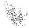
- Figure 1 is an exploded perspective view of an apparatus according to the invention shown adjacent to a resected femur;
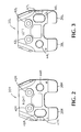
- Figure 2 is a side elevational view of a right knee femoral positioning jig;
- Figure 3 is a side elevational view of a left knee femoral positioning jig;
- Figure 4 is a schematic side elevational view of an apparatus according to the invention coupled to a femur and tibia in a position to apply tension to soft tissues;
- Figure 5 is a side elevational view of an apparatus according to the invention with a right femoral positioning jig installed and shown in a position of zero degrees rotation;
- Figure 6 is a view similar to Figure 5 with the jig shown in a position of five degrees internal (valgus) rotation;
- Figure 7 is a side elevational view of an apparatus according to the invention with a left femoral positioning jig installed and shown in a position of zero degrees rotation; and
- Figure 8 is a view similar to Figure 7 with the jig shown in a position of five degrees internal (valgus) rotation.
-
- Referring now to Figures 1 through 3, the
apparatus 10 of the present invention includes atibia engaging plate 12 which is coupled to anupstanding rack member 14, adrill bushing bracket 16 coupled to therack member 14 by alockable pinion member 18, and afemoral positioning jig 20 which is rotatably coupled to thedrill bushing bracket 16. Thetibia engaging plate 12 has a pair of posterior skids 22, 24 and is coupled to the rackmember base plate 26 by a pair of anterior-posterior positioning rods skids rack member 14. Thedrill bushing bracket 16 has a pair of spaced apartposterior drill bushings lateral condyles 3, 5 of thefemur 7. The centers of thedrill bushings skids tibia engaging plate 12 lies. - The
bushing bracket 16 is also provided (preferably inscribed) with two zero degree reference marks 33, 35 which also lie in the same plane as the centers of thebushings femoral positioning jig 20 is provided with a pair of posterior skids 36, 38, one for the lateral posterior condyle 9 and one for themedial posterior condyle 11, a pair ofholes 40, 42 (preferably anterior bushings) for attaching thejig 20 to the resecteddistal femur 13 with spikes, and a pair ofholes posterior drill bushings - According to one aspect of the invention, the
lateral hole 46 is oblong or kidney shaped and angle indicia 47 are provided on the jig on the lateral side of the lateral hole as described in more detail below. - In accord with the invention, and as shown in Figures 2 and 3, two different femoral positioning jigs 20R, 20L (referred to generally as 20) are provided, one for the right knee and one for the left knee (where right and left are as viewed by the patient). Both jigs are substantially the same but for the relative locations of the
holes - As shown in Figure 2, the
circular hole 44R of theright jig 20R is on the right side of thejig 20R as viewed by the surgeon and theoblong hole 46R is on the left side of thejig 20R as viewed by the surgeon. As shown in Figure 3, thecircular hole 44L of theleft jig 20L is on the left side of thejig 20L as viewed by the surgeon and theoblong hole 46L is on the right side of thejig 20L as viewed by the surgeon.Angle indicia jig hole jigs bushing bracket 16 by sliding the jig onto thebracket 16 such that theposterior drill bushings holes - Referring now to Figures 1 and 4-8, a method of using the
apparatus 10 includes the following steps. After theproximal tibia 15 anddistal femur 7 are resected in a conventional manner, the knee is moved to the flexion position and the femoral positioning jig (20A or 20B, referred to generally as 20) is placed against thedistal end 13 of thefemur 7 with the posterior skids 36, 38 located under theposterior condyles 9,11. - When the jig is in position on the femur, it is secured in place with spikes (not shown) which are placed through the spike holes (anterior bushings) 40, 42 in the jig. The
rack 14 and lockingpinion 18 are adjusted, if necessary, to bring thedrill bushing bracket 16 closest to thetibia engaging plate 12. Thetibia engaging plate 12 is placed on thetibial plateau 17 and thedrill bushings femoral positioning jig 20. The lockingpinion 18 is rotated so that thedrill bushing bracket 16 is moved away from thetibia engaging plate 12 as shown in Figure 4. This results in thefemoral positioning jig 20 and thefemur 7 being moved away from thetibial plateau 17 and a tensioning of the collateral ligaments (not shown). - If the collateral ligaments are of equal length and strength, the femur will not rotate and the
positioning jig 20 will assume the position shown in Figure 5 for the right knee or Figure 7 for the left knee. If the medial ligament is shorter or tighter than the lateral ligament, thefemur 7 and thepositioning jig 20 will rotate in the internal (valgus) direction about the medial drill bushing (32 for the right leg, 34 for the left leg) when the ligaments are fully tensioned. The angle of rotation will be indicated on the scale 47 adjacent theoblong hole 46 in thefemoral positioning jig 20 as shown in Figures 6 and 8. - If the angle is greater than 3 degrees, the surgeon may elect to remove some of the medial collateral ligaments to lessen the degree of rotation. With the
apparatus 10 in this position relative to thetibia 15 and thefemur 7, the axes of thedrill bushings tibial plateau 17. Therefore, after removing ligaments (if necessary), the surgeon drills two holes in thedistal femur 13, one being drilled through eachdrill bushing locking pinion member 18 is then unlocked to remove tension from the ligaments and theapparatus 10 is removed from the knee. Thedistal end 13 of thefemur 7 now has two holes in it and the axes of these holes define a line which is parallel to thetibial plateau 17 when the ligaments are taut. These holes are now used to attach a cutting block which will result in a precise resection of the posterior femoral condyles relative 9, 11 to the resectedtibial plateau 17. - There have been described and illustrated herein a surgical apparatus for use in total knee arthroplasty and a surgical method for using the apparatus. While particular embodiments of the invention have been described, it is not intended that the invention be limited thereto, as it is intended that the invention be as broad in scope as the art will allow and that the specification be read likewise.
- For example, while the apparatus has been shown and described with two different removable positioning jigs, it is within the scope of the invention to provide separate apparatus for left and right legs where the left and right positioning jigs are not removable from the respective apparatus. In addition, while the tibia engaging plate has been shown with two posterior skids, more or fewer skids can achieve substantially the same results. Also, while the apparatus has been shown and described as having a rack and pinion arrangement for moving the drill bushing bracket relative to the tibia engaging plate, it will be appreciated that other designs could achieve the same results in substantially the same way.
- Furthermore, while the femoral positioning jig has been shown as having a particular shape with particular locations for the spike holes, it will be understood that a positioning jig having a different shape can achieve the same results and that different means for securing the jig to the femur can also achieve the same results. It will therefore be appreciated by those skilled in the art that yet other modifications could be made to the provided invention without deviating from its spirit and scope as so claimed.
Claims (16)
- A surgical apparatus 10 for tensioning soft tissues between the femur and the tibia during knee arthroplasty, comprising:(a) first engaging means 12 for engaging a tibial plateau;(b) second engaging means 20,36,38 for engaging medial and lateral femoral condyles;(c) translation means 14,16,18 coupled to said first and second engaging means for translationally moving said engagement means relative to each other; and(d) medial rotational coupling means 32,34 for coupling said second engaging means to said translation means such that said second engaging means is free to rotate about a point substantially aligned with the medial femoral condyle.
- A surgical apparatus according to claim 1, further comprising angle indication means 33,35 for indicating an angle of rotation of said second engaging means.
- A surgical apparatus according to claim 1, further comprising locating means coupled to said translation means 32,34 for locating at least two points on the femur such that the two points define a line which is substantially parallel to the tibial plateau.
- A surgical apparatus according to claim 3, wherein said locating means includes a pair of spaced apart drill bushings 32,34.
- A surgical apparatus according to claim 1, wherein said second engaging means includes means 40,42 for securing said second engaging means to the femur.
- A surgical apparatus according to claim 5, wherein said means for securing includes a pair of spaced apart spike holes 40,42.
- A surgical apparatus according to claim 1, further comprising anterior-posterior positioning means 28,30 for anterior posterior positioning of said first engaging means relative to said second engaging means.
- A surgical apparatus for tensioning soft tissues between the femur and the tibia during knee arthroplasty, comprising:(a) tibial engagement means 12 for engaging a resected tibial plateau;(b) a drill bushing bracket 16 having a lateral drill bushing 32,34 and a medial drill bushing 32,34, each drill bushing having an axis, said axes of said pair of drill bushings defining a first plane;(c) translation means 14,16 coupled to said tibial engagement means 12 and said drill bushing bracket 16 for translationally moving said drill bushing bracket relative to said tibial engagement means; and(d) a femoral positioning jig 20 rotationally coupled to said medial drill bushing, said femoral positioning jig having a posterior medial condyle engaging skid 30, a posterior lateral condyle engaging skid 36, and means for securing the position of said jig relative to the femur 40,42, wherein said first plane remains substantially parallel to the resected tibial plateau when said tibial engagement means engages the plateau, and said positioning jig and the femur are free to rotate about said medial drill bushing when said positioning jig is secured to the femur.
- A surgical apparatus according to claim 8, further comprising angle indicia 33,35 for indicating an angle of rotation of the femur about said medial drill bushing.
- A surgical apparatus according to claim 8, wherein said positioning jig has a substantially circular medial hole 44 for receiving said medial drill bushing and a substantially oblong lateral hole 46 for receiving said lateral drill bushing, such that said rotational coupling of said positioning jig is effected by inserting said medial drill bushing into said medial hole and said lateral drill bushing into said lateral hole.
- A surgical apparatus according to claim 10, wherein said positioning jig is removably coupled to said medial drill bushing.
- A surgical apparatus according to claim 11, further comprising separate left and right positioning jigs, said left positioning jig for use with a left leg and said right positioning jig for use with a right leg.
- A surgical apparatus according to claim 9, wherein said angle indicia includes indicia 33,35 on a lateral portion of said drill bushing bracket 16 and indicia on a lateral portion of said positioning jig 20.
- A surgical apparatus according to claim 9, wherein said translation means includes a rack 14 and pinion 16.
- A surgical apparatus according to claim 8, wherein said tibia engagement means includes a lateral posterior skid 22 and a medial posterior skid 24.
- A surgical apparatus according to claim 8, wherein said means for securing the position of said jig relative to the femur includes a pair of spike holes 40,42 in said positioning jig.
Applications Claiming Priority (2)
| Application Number | Priority Date | Filing Date | Title |
|---|---|---|---|
| US08/929,034 US5860980A (en) | 1997-09-15 | 1997-09-15 | Surgical apparatus for use in total knee arthroplasty and surgical methods for using said apparatus |
| US929034 | 1997-09-15 |
Publications (3)
| Publication Number | Publication Date |
|---|---|
| EP0903111A2 true EP0903111A2 (en) | 1999-03-24 |
| EP0903111A3 EP0903111A3 (en) | 2002-10-30 |
| EP0903111B1 EP0903111B1 (en) | 2004-03-03 |
Family
ID=25457217
Family Applications (1)
| Application Number | Title | Priority Date | Filing Date |
|---|---|---|---|
| EP98306816A Expired - Lifetime EP0903111B1 (en) | 1997-09-15 | 1998-08-26 | Surgical apparatus for use in total knee arthroplasty |
Country Status (4)
| Country | Link |
|---|---|
| US (1) | US5860980A (en) |
| EP (1) | EP0903111B1 (en) |
| JP (1) | JPH11164845A (en) |
| DE (1) | DE69822055T2 (en) |
Cited By (1)
| Publication number | Priority date | Publication date | Assignee | Title |
|---|---|---|---|---|
| GB2482702A (en) * | 2010-08-11 | 2012-02-15 | Biomet Uk Healthcare Ltd | Ligament balancer |
Families Citing this family (193)
| Publication number | Priority date | Publication date | Assignee | Title |
|---|---|---|---|---|
| US6056756A (en) * | 1998-08-11 | 2000-05-02 | Johnson & Johnson Professional, Inc. | Femoral tensing and sizing device |
| US6174314B1 (en) * | 1998-12-15 | 2001-01-16 | David D. Waddell | In situ pattellar resection guide |
| ATE484241T1 (en) * | 1999-04-09 | 2010-10-15 | Evalve Inc | METHOD AND DEVICE FOR HEART VALVE REPAIR |
| US7104996B2 (en) * | 2000-01-14 | 2006-09-12 | Marctec. Llc | Method of performing surgery |
| US6702821B2 (en) | 2000-01-14 | 2004-03-09 | The Bonutti 2003 Trust A | Instrumentation for minimally invasive joint replacement and methods for using same |
| US7635390B1 (en) * | 2000-01-14 | 2009-12-22 | Marctec, Llc | Joint replacement component having a modular articulating surface |
| US6342057B1 (en) | 2000-04-28 | 2002-01-29 | Synthes (Usa) | Remotely aligned surgical drill guide |
| US6379364B1 (en) | 2000-04-28 | 2002-04-30 | Synthes (Usa) | Dual drill guide for a locking bone plate |
| US6458135B1 (en) * | 2001-02-02 | 2002-10-01 | Howmedica Osteonics Corp. | Femoral guide for implanting a femoral knee prosthesis and method |
| US6629978B2 (en) * | 2001-04-23 | 2003-10-07 | Howmedica Osteonics Corp. | Valgus adapter |
| US7708741B1 (en) | 2001-08-28 | 2010-05-04 | Marctec, Llc | Method of preparing bones for knee replacement surgery |
| US8801720B2 (en) * | 2002-05-15 | 2014-08-12 | Otismed Corporation | Total joint arthroplasty system |
| US7001433B2 (en) * | 2002-05-23 | 2006-02-21 | Pioneer Laboratories, Inc. | Artificial intervertebral disc device |
| US8388684B2 (en) * | 2002-05-23 | 2013-03-05 | Pioneer Signal Technology, Inc. | Artificial disc device |
| EP1555963A4 (en) * | 2002-10-23 | 2008-12-31 | Mako Surgical Corp | Modular femoral component for a total knee joint replacement for minimally invasive implantation |
| US7094241B2 (en) * | 2002-11-27 | 2006-08-22 | Zimmer Technology, Inc. | Method and apparatus for achieving correct limb alignment in unicondylar knee arthroplasty |
| US7029477B2 (en) * | 2002-12-20 | 2006-04-18 | Zimmer Technology, Inc. | Surgical instrument and positioning method |
| US8551100B2 (en) | 2003-01-15 | 2013-10-08 | Biomet Manufacturing, Llc | Instrumentation for knee resection |
| US7789885B2 (en) * | 2003-01-15 | 2010-09-07 | Biomet Manufacturing Corp. | Instrumentation for knee resection |
| US7887542B2 (en) * | 2003-01-15 | 2011-02-15 | Biomet Manufacturing Corp. | Method and apparatus for less invasive knee resection |
| US7837690B2 (en) * | 2003-01-15 | 2010-11-23 | Biomet Manufacturing Corp. | Method and apparatus for less invasive knee resection |
| US6916324B2 (en) * | 2003-02-04 | 2005-07-12 | Zimmer Technology, Inc. | Provisional orthopedic prosthesis for partially resected bone |
| US7235080B2 (en) * | 2003-02-20 | 2007-06-26 | Zimmer Technology, Inc. | Femoral reference tibial cut guide |
| ES2261812T3 (en) * | 2003-04-25 | 2006-11-16 | Zimmer Gmbh | DEVICE FOR THE PREPARATION OF A FEMORAL CONDILO. |
| FR2857576B1 (en) * | 2003-07-16 | 2005-10-14 | Depuy France | ASSISTING DEVICE FOR THE IMPLANTATION OF TOTAL KNEE PROSTHESES |
| US7686810B2 (en) * | 2003-08-29 | 2010-03-30 | Hs West Investments, Llc | Suture separation and organization devices for use with graft tensioning device |
| EP1491166B1 (en) | 2003-09-15 | 2005-03-02 | Zimmer GmbH | Adjusting device |
| US7585328B2 (en) * | 2003-11-06 | 2009-09-08 | Haas Steven B | Minimally invasive knee arthroplasty |
| US7488324B1 (en) * | 2003-12-08 | 2009-02-10 | Biomet Manufacturing Corporation | Femoral guide for implanting a femoral knee prosthesis |
| US7641661B2 (en) | 2003-12-26 | 2010-01-05 | Zimmer Technology, Inc. | Adjustable resection guide |
| US7282054B2 (en) * | 2003-12-26 | 2007-10-16 | Zimmer Technology, Inc. | Adjustable cut block |
| US8758355B2 (en) | 2004-02-06 | 2014-06-24 | Synvasive Technology, Inc. | Dynamic knee balancer with pressure sensing |
| US7442196B2 (en) * | 2004-02-06 | 2008-10-28 | Synvasive Technology, Inc. | Dynamic knee balancer |
| US8167888B2 (en) * | 2004-08-06 | 2012-05-01 | Zimmer Technology, Inc. | Tibial spacer blocks and femoral cutting guide |
| WO2006069260A1 (en) | 2004-12-21 | 2006-06-29 | Smith & Nephew, Inc. | Distal femoral trial with removable cutting guide |
| US8303597B2 (en) * | 2005-02-08 | 2012-11-06 | Rasmussen G Lynn | Systems and methods for guiding cuts to a femur and tibia during a knee arthroplasty |
| US8317797B2 (en) | 2005-02-08 | 2012-11-27 | Rasmussen G Lynn | Arthroplasty systems and methods for optimally aligning and tensioning a knee prosthesis |
| US7695479B1 (en) | 2005-04-12 | 2010-04-13 | Biomet Manufacturing Corp. | Femoral sizer |
| US20050267484A1 (en) * | 2005-08-18 | 2005-12-01 | Jeff Menzner | Extended trochanteric osteotomy guide |
| US7780671B2 (en) * | 2006-01-23 | 2010-08-24 | Zimmer Technology, Inc. | Bone resection apparatus and method for knee surgery |
| CA2642615A1 (en) * | 2006-02-15 | 2007-08-30 | Otismed Corp | Arthroplasty jigs and related methods |
| US9808262B2 (en) * | 2006-02-15 | 2017-11-07 | Howmedica Osteonics Corporation | Arthroplasty devices and related methods |
| US20110190899A1 (en) * | 2006-02-27 | 2011-08-04 | Biomet Manufacturing Corp. | Patient-specific augments |
| US9907659B2 (en) * | 2007-04-17 | 2018-03-06 | Biomet Manufacturing, Llc | Method and apparatus for manufacturing an implant |
| US8603180B2 (en) | 2006-02-27 | 2013-12-10 | Biomet Manufacturing, Llc | Patient-specific acetabular alignment guides |
| US9173661B2 (en) | 2006-02-27 | 2015-11-03 | Biomet Manufacturing, Llc | Patient specific alignment guide with cutting surface and laser indicator |
| US7967868B2 (en) | 2007-04-17 | 2011-06-28 | Biomet Manufacturing Corp. | Patient-modified implant and associated method |
| US8535387B2 (en) | 2006-02-27 | 2013-09-17 | Biomet Manufacturing, Llc | Patient-specific tools and implants |
| US8591516B2 (en) | 2006-02-27 | 2013-11-26 | Biomet Manufacturing, Llc | Patient-specific orthopedic instruments |
| US20150335438A1 (en) | 2006-02-27 | 2015-11-26 | Biomet Manufacturing, Llc. | Patient-specific augments |
| US8407067B2 (en) | 2007-04-17 | 2013-03-26 | Biomet Manufacturing Corp. | Method and apparatus for manufacturing an implant |
| US8608749B2 (en) | 2006-02-27 | 2013-12-17 | Biomet Manufacturing, Llc | Patient-specific acetabular guides and associated instruments |
| US8864769B2 (en) * | 2006-02-27 | 2014-10-21 | Biomet Manufacturing, Llc | Alignment guides with patient-specific anchoring elements |
| US8133234B2 (en) | 2006-02-27 | 2012-03-13 | Biomet Manufacturing Corp. | Patient specific acetabular guide and method |
| US8377066B2 (en) | 2006-02-27 | 2013-02-19 | Biomet Manufacturing Corp. | Patient-specific elbow guides and associated methods |
| US9339278B2 (en) | 2006-02-27 | 2016-05-17 | Biomet Manufacturing, Llc | Patient-specific acetabular guides and associated instruments |
| US9289253B2 (en) | 2006-02-27 | 2016-03-22 | Biomet Manufacturing, Llc | Patient-specific shoulder guide |
| US8070752B2 (en) * | 2006-02-27 | 2011-12-06 | Biomet Manufacturing Corp. | Patient specific alignment guide and inter-operative adjustment |
| US9345548B2 (en) | 2006-02-27 | 2016-05-24 | Biomet Manufacturing, Llc | Patient-specific pre-operative planning |
| US8858561B2 (en) * | 2006-06-09 | 2014-10-14 | Blomet Manufacturing, LLC | Patient-specific alignment guide |
| US20110172672A1 (en) * | 2006-02-27 | 2011-07-14 | Biomet Manufacturing Corp. | Instrument with transparent portion for use with patient-specific alignment guide |
| US9113971B2 (en) * | 2006-02-27 | 2015-08-25 | Biomet Manufacturing, Llc | Femoral acetabular impingement guide |
| US8568487B2 (en) | 2006-02-27 | 2013-10-29 | Biomet Manufacturing, Llc | Patient-specific hip joint devices |
| US10278711B2 (en) * | 2006-02-27 | 2019-05-07 | Biomet Manufacturing, Llc | Patient-specific femoral guide |
| US7780672B2 (en) * | 2006-02-27 | 2010-08-24 | Biomet Manufacturing Corp. | Femoral adjustment device and associated method |
| US8092465B2 (en) | 2006-06-09 | 2012-01-10 | Biomet Manufacturing Corp. | Patient specific knee alignment guide and associated method |
| US9918740B2 (en) | 2006-02-27 | 2018-03-20 | Biomet Manufacturing, Llc | Backup surgical instrument system and method |
| US8241293B2 (en) | 2006-02-27 | 2012-08-14 | Biomet Manufacturing Corp. | Patient specific high tibia osteotomy |
| US8608748B2 (en) | 2006-02-27 | 2013-12-17 | Biomet Manufacturing, Llc | Patient specific guides |
| US8231631B2 (en) * | 2006-03-20 | 2012-07-31 | Perception Raisonnement Action En Medecine | Distractor system |
| US8337508B2 (en) | 2006-03-20 | 2012-12-25 | Perception Raisonnement Action En Medecine | Distractor system |
| GB0610572D0 (en) * | 2006-05-27 | 2006-07-05 | Depuy Int Ltd | Guide assembly |
| US8273131B2 (en) * | 2006-05-31 | 2012-09-25 | Biomet Manufacturing Corp. | Method and apparatus for positioning a multiple piece prosthesis |
| US9795399B2 (en) | 2006-06-09 | 2017-10-24 | Biomet Manufacturing, Llc | Patient-specific knee alignment guide and associated method |
| US7686812B2 (en) * | 2006-06-30 | 2010-03-30 | Howmedica Osteonics Corp. | Method for setting the rotational position of a femoral component |
| EP2063817A4 (en) * | 2006-09-15 | 2012-04-18 | Pioneer Surgical Technology Inc | Joint arthroplasty devices having articulating members |
| US8715350B2 (en) | 2006-09-15 | 2014-05-06 | Pioneer Surgical Technology, Inc. | Systems and methods for securing an implant in intervertebral space |
| ES2542434T3 (en) * | 2006-10-11 | 2015-08-05 | Ignace Ghijselings | Device for installing a femoral prosthetic knee joint |
| CA2670175C (en) | 2006-10-31 | 2014-12-16 | Smith & Nephew, Inc. | Trial femoral prosthesis and its use |
| US8460302B2 (en) * | 2006-12-18 | 2013-06-11 | Otismed Corporation | Arthroplasty devices and related methods |
| GB2447702A (en) | 2007-03-23 | 2008-09-24 | Univ Leeds | Surgical bone cutting template |
| US8265949B2 (en) | 2007-09-27 | 2012-09-11 | Depuy Products, Inc. | Customized patient surgical plan |
| ES2802126T3 (en) | 2007-09-30 | 2021-01-15 | Depuy Products Inc | Patient Specific Custom Orthopedic Surgical Instrument |
| US8357111B2 (en) | 2007-09-30 | 2013-01-22 | Depuy Products, Inc. | Method and system for designing patient-specific orthopaedic surgical instruments |
| US8460303B2 (en) | 2007-10-25 | 2013-06-11 | Otismed Corporation | Arthroplasty systems and devices, and related methods |
| USD642263S1 (en) | 2007-10-25 | 2011-07-26 | Otismed Corporation | Arthroplasty jig blank |
| US10582934B2 (en) | 2007-11-27 | 2020-03-10 | Howmedica Osteonics Corporation | Generating MRI images usable for the creation of 3D bone models employed to make customized arthroplasty jigs |
| US8715291B2 (en) * | 2007-12-18 | 2014-05-06 | Otismed Corporation | Arthroplasty system and related methods |
| US8545509B2 (en) | 2007-12-18 | 2013-10-01 | Otismed Corporation | Arthroplasty system and related methods |
| US8480679B2 (en) | 2008-04-29 | 2013-07-09 | Otismed Corporation | Generation of a computerized bone model representative of a pre-degenerated state and useable in the design and manufacture of arthroplasty devices |
| US8160345B2 (en) | 2008-04-30 | 2012-04-17 | Otismed Corporation | System and method for image segmentation in generating computer models of a joint to undergo arthroplasty |
| US8617171B2 (en) | 2007-12-18 | 2013-12-31 | Otismed Corporation | Preoperatively planning an arthroplasty procedure and generating a corresponding patient specific arthroplasty resection guide |
| US8777875B2 (en) * | 2008-07-23 | 2014-07-15 | Otismed Corporation | System and method for manufacturing arthroplasty jigs having improved mating accuracy |
| US8311306B2 (en) * | 2008-04-30 | 2012-11-13 | Otismed Corporation | System and method for image segmentation in generating computer models of a joint to undergo arthroplasty |
| US8737700B2 (en) * | 2007-12-18 | 2014-05-27 | Otismed Corporation | Preoperatively planning an arthroplasty procedure and generating a corresponding patient specific arthroplasty resection guide |
| US8221430B2 (en) * | 2007-12-18 | 2012-07-17 | Otismed Corporation | System and method for manufacturing arthroplasty jigs |
| US8734455B2 (en) * | 2008-02-29 | 2014-05-27 | Otismed Corporation | Hip resurfacing surgical guide tool |
| US8197489B2 (en) | 2008-06-27 | 2012-06-12 | Depuy Products, Inc. | Knee ligament balancer |
| US8617175B2 (en) * | 2008-12-16 | 2013-12-31 | Otismed Corporation | Unicompartmental customized arthroplasty cutting jigs and methods of making the same |
| US8337498B2 (en) | 2008-08-13 | 2012-12-25 | Rasmussen G Lynn | Systems and methods for providing a bone milling device |
| JP2012500667A (en) | 2008-08-20 | 2012-01-12 | シンバシブ テクノロジー インコーポレイティッド | Force sensing method for partial and total knee arthroplasty |
| US9439656B2 (en) | 2008-10-30 | 2016-09-13 | Synvasive Technology, Inc. | System for positioning a cutting guide in knee surgery |
| US20100198275A1 (en) * | 2008-10-30 | 2010-08-05 | Synvavise Technology, Inc. | Force sensing distal femoral alignment system and method of use |
| US8597210B2 (en) | 2009-03-31 | 2013-12-03 | Depuy (Ireland) | System and method for displaying joint force data |
| US8551023B2 (en) * | 2009-03-31 | 2013-10-08 | Depuy (Ireland) | Device and method for determining force of a knee joint |
| US8556830B2 (en) | 2009-03-31 | 2013-10-15 | Depuy | Device and method for displaying joint force data |
| US8721568B2 (en) * | 2009-03-31 | 2014-05-13 | Depuy (Ireland) | Method for performing an orthopaedic surgical procedure |
| US8740817B2 (en) | 2009-03-31 | 2014-06-03 | Depuy (Ireland) | Device and method for determining forces of a patient's joint |
| US8216244B2 (en) * | 2009-06-19 | 2012-07-10 | Wright Medical Technology, Inc. | Midline referencing femoral sizing caliper |
| FR2948274B1 (en) * | 2009-07-24 | 2011-09-16 | Tornier Sa | SURGICAL INSTRUMENTATION FOR THE PREPARATION FOR THE INSTALLATION OF A KNEE PROSTHESIS |
| DE102009028503B4 (en) | 2009-08-13 | 2013-11-14 | Biomet Manufacturing Corp. | Resection template for the resection of bones, method for producing such a resection template and operation set for performing knee joint surgery |
| CA2778040A1 (en) * | 2009-10-23 | 2011-04-28 | Synvasive Technology, Inc. | Knee balancing for revision procedures |
| US8632547B2 (en) | 2010-02-26 | 2014-01-21 | Biomet Sports Medicine, Llc | Patient-specific osteotomy devices and methods |
| GB2479899A (en) | 2010-04-28 | 2011-11-02 | Biomet Uk Ltd | Alignment tool for use in joint replacement |
| US9271744B2 (en) | 2010-09-29 | 2016-03-01 | Biomet Manufacturing, Llc | Patient-specific guide for partial acetabular socket replacement |
| US9968376B2 (en) | 2010-11-29 | 2018-05-15 | Biomet Manufacturing, Llc | Patient-specific orthopedic instruments |
| US8672946B2 (en) * | 2011-02-11 | 2014-03-18 | Biomet Manfacturing, LLC | Method and apparatus for performing knee arthroplasty |
| US9241745B2 (en) | 2011-03-07 | 2016-01-26 | Biomet Manufacturing, Llc | Patient-specific femoral version guide |
| US8715289B2 (en) | 2011-04-15 | 2014-05-06 | Biomet Manufacturing, Llc | Patient-specific numerically controlled instrument |
| US8668700B2 (en) | 2011-04-29 | 2014-03-11 | Biomet Manufacturing, Llc | Patient-specific convertible guides |
| US8956364B2 (en) | 2011-04-29 | 2015-02-17 | Biomet Manufacturing, Llc | Patient-specific partial knee guides and other instruments |
| CH704354B1 (en) * | 2011-05-17 | 2012-07-13 | Medacta Int Sa | Equipment to align and balance the ligaments of the knee. |
| US8532807B2 (en) | 2011-06-06 | 2013-09-10 | Biomet Manufacturing, Llc | Pre-operative planning and manufacturing method for orthopedic procedure |
| US9084618B2 (en) | 2011-06-13 | 2015-07-21 | Biomet Manufacturing, Llc | Drill guides for confirming alignment of patient-specific alignment guides |
| US20130006378A1 (en) | 2011-06-30 | 2013-01-03 | Wogoman Thomas E | Polymer femoral trial component |
| US8968412B2 (en) | 2011-06-30 | 2015-03-03 | Depuy (Ireland) | Trialing system for a knee prosthesis and method of use |
| US8986390B2 (en) | 2011-06-30 | 2015-03-24 | Depuy (Ireland) | Method of trialing a knee prosthesis |
| US8926619B2 (en) | 2011-06-30 | 2015-01-06 | Depuy (Ireland) | Method of surgically preparing a tibia for implantation of a prosthetic component |
| US8939986B2 (en) | 2011-06-30 | 2015-01-27 | Depuy (Ireland) | Surgical instruments for use in surgically preparing a tibia for implantation of a prosthetic component |
| US8852197B2 (en) | 2011-06-30 | 2014-10-07 | Depuy (Ireland) | Surgical instrument assemblies for use in surgically preparing a tibia for implantation of a prosthetic component |
| US8951301B2 (en) | 2011-06-30 | 2015-02-10 | Depuy (Ireland) | Method of using a trialing system for a knee prosthesis |
| US8764760B2 (en) | 2011-07-01 | 2014-07-01 | Biomet Manufacturing, Llc | Patient-specific bone-cutting guidance instruments and methods |
| US20130001121A1 (en) | 2011-07-01 | 2013-01-03 | Biomet Manufacturing Corp. | Backup kit for a patient-specific arthroplasty kit assembly |
| WO2013013094A1 (en) * | 2011-07-19 | 2013-01-24 | Zimmer, Inc. | Knee arthroplasty instrument |
| US8597365B2 (en) | 2011-08-04 | 2013-12-03 | Biomet Manufacturing, Llc | Patient-specific pelvic implants for acetabular reconstruction |
| US9295497B2 (en) | 2011-08-31 | 2016-03-29 | Biomet Manufacturing, Llc | Patient-specific sacroiliac and pedicle guides |
| US9066734B2 (en) | 2011-08-31 | 2015-06-30 | Biomet Manufacturing, Llc | Patient-specific sacroiliac guides and associated methods |
| GB201115411D0 (en) | 2011-09-07 | 2011-10-19 | Depuy Ireland | Surgical instrument |
| US9918723B2 (en) * | 2011-09-23 | 2018-03-20 | Depuy Mitek, Llc | Glenoid anchor guide |
| WO2013063043A1 (en) | 2011-10-24 | 2013-05-02 | Synvasive Technology, Inc. | Knee balancing devices, systems and methods |
| KR20130046337A (en) | 2011-10-27 | 2013-05-07 | 삼성전자주식회사 | Multi-view device and contol method thereof, display apparatus and contol method thereof, and display system |
| US9554910B2 (en) | 2011-10-27 | 2017-01-31 | Biomet Manufacturing, Llc | Patient-specific glenoid guide and implants |
| US9451973B2 (en) | 2011-10-27 | 2016-09-27 | Biomet Manufacturing, Llc | Patient specific glenoid guide |
| WO2013062848A1 (en) | 2011-10-27 | 2013-05-02 | Biomet Manufacturing Corporation | Patient-specific glenoid guides |
| US9301812B2 (en) | 2011-10-27 | 2016-04-05 | Biomet Manufacturing, Llc | Methods for patient-specific shoulder arthroplasty |
| US9241807B2 (en) | 2011-12-23 | 2016-01-26 | Pioneer Surgical Technology, Inc. | Systems and methods for inserting a spinal device |
| US9237950B2 (en) | 2012-02-02 | 2016-01-19 | Biomet Manufacturing, Llc | Implant with patient-specific porous structure |
| US9381011B2 (en) | 2012-03-29 | 2016-07-05 | Depuy (Ireland) | Orthopedic surgical instrument for knee surgery |
| US10070973B2 (en) | 2012-03-31 | 2018-09-11 | Depuy Ireland Unlimited Company | Orthopaedic sensor module and system for determining joint forces of a patient's knee joint |
| US9545459B2 (en) | 2012-03-31 | 2017-01-17 | Depuy Ireland Unlimited Company | Container for surgical instruments and system including same |
| US10206792B2 (en) | 2012-03-31 | 2019-02-19 | Depuy Ireland Unlimited Company | Orthopaedic surgical system for determining joint forces of a patients knee joint |
| US10098761B2 (en) | 2012-03-31 | 2018-10-16 | DePuy Synthes Products, Inc. | System and method for validating an orthopaedic surgical plan |
| US9050197B2 (en) * | 2012-07-23 | 2015-06-09 | Biomet Manufacturing, Llc | Knee sizing and balancing instrument |
| GB2506616B (en) * | 2012-10-03 | 2018-12-05 | Corin Ltd | Leg alignment apparatus and method |
| US9402637B2 (en) | 2012-10-11 | 2016-08-02 | Howmedica Osteonics Corporation | Customized arthroplasty cutting guides and surgical methods using the same |
| US9204977B2 (en) | 2012-12-11 | 2015-12-08 | Biomet Manufacturing, Llc | Patient-specific acetabular guide for anterior approach |
| US9060788B2 (en) | 2012-12-11 | 2015-06-23 | Biomet Manufacturing, Llc | Patient-specific acetabular guide for anterior approach |
| GB201302782D0 (en) * | 2013-02-18 | 2013-04-03 | Depuy Ireland | A guide for locating a cutting block on a patient's femur |
| US9839438B2 (en) | 2013-03-11 | 2017-12-12 | Biomet Manufacturing, Llc | Patient-specific glenoid guide with a reusable guide holder |
| US9579107B2 (en) | 2013-03-12 | 2017-02-28 | Biomet Manufacturing, Llc | Multi-point fit for patient specific guide |
| US9498233B2 (en) | 2013-03-13 | 2016-11-22 | Biomet Manufacturing, Llc. | Universal acetabular guide and associated hardware |
| US9826981B2 (en) | 2013-03-13 | 2017-11-28 | Biomet Manufacturing, Llc | Tangential fit of patient-specific guides |
| US9517145B2 (en) | 2013-03-15 | 2016-12-13 | Biomet Manufacturing, Llc | Guide alignment system and method |
| GB2516674A (en) * | 2013-07-29 | 2015-02-04 | Ramesh Chandra | Orthopaedic Apparatus |
| US20150112349A1 (en) | 2013-10-21 | 2015-04-23 | Biomet Manufacturing, Llc | Ligament Guide Registration |
| JP6336811B2 (en) * | 2014-04-16 | 2018-06-06 | ジンマー・バイオメット合同会社 | Artificial knee joint installation jig |
| US10282488B2 (en) | 2014-04-25 | 2019-05-07 | Biomet Manufacturing, Llc | HTO guide with optional guided ACL/PCL tunnels |
| US9861491B2 (en) | 2014-04-30 | 2018-01-09 | Depuy Ireland Unlimited Company | Tibial trial system for a knee prosthesis |
| US9408616B2 (en) | 2014-05-12 | 2016-08-09 | Biomet Manufacturing, Llc | Humeral cut guide |
| US9561040B2 (en) | 2014-06-03 | 2017-02-07 | Biomet Manufacturing, Llc | Patient-specific glenoid depth control |
| US9839436B2 (en) | 2014-06-03 | 2017-12-12 | Biomet Manufacturing, Llc | Patient-specific glenoid depth control |
| US9833245B2 (en) | 2014-09-29 | 2017-12-05 | Biomet Sports Medicine, Llc | Tibial tubercule osteotomy |
| US9826994B2 (en) | 2014-09-29 | 2017-11-28 | Biomet Manufacturing, Llc | Adjustable glenoid pin insertion guide |
| CN107106189B (en) | 2014-11-19 | 2019-12-13 | 捷迈有限公司 | Gap calibration femur measurer |
| US9820868B2 (en) | 2015-03-30 | 2017-11-21 | Biomet Manufacturing, Llc | Method and apparatus for a pin apparatus |
| US10568647B2 (en) | 2015-06-25 | 2020-02-25 | Biomet Manufacturing, Llc | Patient-specific humeral guide designs |
| US10226262B2 (en) | 2015-06-25 | 2019-03-12 | Biomet Manufacturing, Llc | Patient-specific humeral guide designs |
| US10537445B2 (en) | 2015-10-19 | 2020-01-21 | Depuy Ireland Unlimited Company | Surgical instruments for preparing a patient's tibia to receive an implant |
| US10195056B2 (en) | 2015-10-19 | 2019-02-05 | Depuy Ireland Unlimited Company | Method for preparing a patient's tibia to receive an implant |
| EP3457994B1 (en) * | 2016-05-19 | 2022-12-28 | Cabot, Jonathan Peter | An arrangement and method in the preparation of the distal femur and posterior femoral condyle proximal surfaces of the femur for the femoral component of a prosthetic knee joint |
| EP3474725A1 (en) | 2016-06-24 | 2019-05-01 | Surgical Sensors BVBA | Integrated ligament strain measurement |
| US11284873B2 (en) | 2016-12-22 | 2022-03-29 | Orthosensor Inc. | Surgical tensor where each distraction mechanism is supported and aligned by at least two guide shafts |
| US11291437B2 (en) | 2016-12-22 | 2022-04-05 | Orthosensor Inc. | Tilting surgical tensor to support at least one bone cut |
| US11185425B2 (en) | 2016-12-22 | 2021-11-30 | Orthosensor Inc. | Surgical tensor configured to distribute loading through at least two pivot points |
| US10772641B2 (en) | 2016-12-22 | 2020-09-15 | Orthosensor Inc. | Surgical apparatus having a frame and moving support structure and method therefore |
| US11266512B2 (en) | 2016-12-22 | 2022-03-08 | Orthosensor Inc. | Surgical apparatus to support installation of a prosthetic component and method therefore |
| US11540928B2 (en) * | 2017-03-03 | 2023-01-03 | Engage Uni Llc | Unicompartmental knee arthroplasty |
| US10722310B2 (en) | 2017-03-13 | 2020-07-28 | Zimmer Biomet CMF and Thoracic, LLC | Virtual surgery planning system and method |
| WO2019022769A1 (en) | 2017-07-28 | 2019-01-31 | Wright Medical Technology, Inc. | Joint osteotomy system and method |
| EP3678602A4 (en) | 2017-09-08 | 2021-10-06 | Pioneer Surgical Technology, Inc. | Intervertebral implants, instruments, and methods |
| USD907771S1 (en) | 2017-10-09 | 2021-01-12 | Pioneer Surgical Technology, Inc. | Intervertebral implant |
| US11051829B2 (en) | 2018-06-26 | 2021-07-06 | DePuy Synthes Products, Inc. | Customized patient-specific orthopaedic surgical instrument |
| AU2020356372A1 (en) * | 2019-09-24 | 2022-04-14 | Mako Surgical Corp. | System and method for ligament balancing using robotically held device |
Citations (1)
| Publication number | Priority date | Publication date | Assignee | Title |
|---|---|---|---|---|
| US5468244A (en) | 1991-11-06 | 1995-11-21 | Howmedica International, Inc. | Surgical apparatus for use in joint replacement surgery |
Family Cites Families (5)
| Publication number | Priority date | Publication date | Assignee | Title |
|---|---|---|---|---|
| US4566448A (en) * | 1983-03-07 | 1986-01-28 | Rohr Jr William L | Ligament tensor and distal femoral resector guide |
| US5116338A (en) * | 1988-02-03 | 1992-05-26 | Pfizer Hospital Products Group, Inc. | Apparatus for knee prosthesis |
| US5213112A (en) * | 1992-01-29 | 1993-05-25 | Pfizer Hospital Products Group, Inc. | Tension meter for orthopedic surgery |
| US5597379A (en) * | 1994-09-02 | 1997-01-28 | Hudson Surgical Design, Inc. | Method and apparatus for femoral resection alignment |
| US5540696A (en) * | 1995-01-06 | 1996-07-30 | Zimmer, Inc. | Instrumentation for use in orthopaedic surgery |
-
1997
- 1997-09-15 US US08/929,034 patent/US5860980A/en not_active Expired - Lifetime
-
1998
- 1998-08-26 DE DE69822055T patent/DE69822055T2/en not_active Expired - Fee Related
- 1998-08-26 EP EP98306816A patent/EP0903111B1/en not_active Expired - Lifetime
- 1998-09-14 JP JP10259672A patent/JPH11164845A/en active Pending
Patent Citations (1)
| Publication number | Priority date | Publication date | Assignee | Title |
|---|---|---|---|---|
| US5468244A (en) | 1991-11-06 | 1995-11-21 | Howmedica International, Inc. | Surgical apparatus for use in joint replacement surgery |
Cited By (3)
| Publication number | Priority date | Publication date | Assignee | Title |
|---|---|---|---|---|
| GB2482702A (en) * | 2010-08-11 | 2012-02-15 | Biomet Uk Healthcare Ltd | Ligament balancer |
| US9168032B2 (en) | 2010-08-11 | 2015-10-27 | Biomet Manufacturing, Llc | Ligament balancer and drill guide |
| US9962172B2 (en) | 2010-08-11 | 2018-05-08 | Biomet Manufacturing, Llc | Ligament balancer and drill guide |
Also Published As
| Publication number | Publication date |
|---|---|
| US5860980A (en) | 1999-01-19 |
| DE69822055D1 (en) | 2004-04-08 |
| EP0903111B1 (en) | 2004-03-03 |
| EP0903111A3 (en) | 2002-10-30 |
| DE69822055T2 (en) | 2004-07-22 |
| JPH11164845A (en) | 1999-06-22 |
Similar Documents
| Publication | Publication Date | Title |
|---|---|---|
| EP0903111B1 (en) | Surgical apparatus for use in total knee arthroplasty | |
| US9855057B2 (en) | Natural alignment knee instruments | |
| US6059788A (en) | Method and apparatus for locating bone cuts at the distal condylar femur region to receive a femoral prosthesis and properly articulated with patellar and tibial prosthesis | |
| US5720752A (en) | Distal femoral cutting guide apparatus with anterior or posterior referencing for use in knee joint replacement surgery | |
| US6758850B2 (en) | Instruments and methods for flexion gap adjustment | |
| US6575980B1 (en) | Method and apparatus for femoral resection | |
| US6077270A (en) | Method and apparatus for locating bone cuts at the distal condylar femur region to receive a femoral prothesis and to coordinate tibial and patellar resection and replacement with femoral resection and replacement | |
| EP0975262B1 (en) | Instrument for evaluating balance of knee joint | |
| US8454616B2 (en) | Method and apparatus for achieving correct limb alignment in unicondylar knee arthroplasty | |
| US7329260B2 (en) | Kit, guide and method for locating distal femoral resection plane | |
| US20110046685A1 (en) | Surgical instrument for fitting a knee prosthesis | |
| JP2001525536A (en) | Method and apparatus for positioning a resection in the distal condyle of the femur, tibia and patella | |
| WO1995013034A1 (en) | Distal femoral cutting guide with referencing | |
| US20240081835A1 (en) | Knee resection and gap balancing instruments and techniques for kinematic alignment | |
| WO1998032384A9 (en) | Method and apparatus for femoral resection | |
| EP2953559A1 (en) | Total knee arthroplasty methods, systems, and instruments | |
| AU2005202181A1 (en) | Navigated lateral/medial femoral resection guide | |
| GB2495775A (en) | Femoral sizing jig, femur resecting system and method | |
| WO2016153927A1 (en) | Disposable multi-purpose tool for total knee arthroplasty | |
| US9005208B2 (en) | Ligament balancing femoral trial | |
| US20210100568A1 (en) | Cutting and drilling template for unicondylar knee arthroplasty | |
| Cooke et al. | Universal bone cutting device for precision knee replacement arthroplasty and osteotomy | |
| WO2018104704A1 (en) | Apparatus for alignment of knee arthroplasty tibial cutting block | |
| US20210228377A1 (en) | Load Sensor Balancer Instruments | |
| Sathappan et al. | Correlation between the distal anterior femoral cortical axis and femoral rotational alignment: an anatomic study |
Legal Events
| Date | Code | Title | Description |
|---|---|---|---|
| PUAI | Public reference made under article 153(3) epc to a published international application that has entered the european phase |
Free format text: ORIGINAL CODE: 0009012 |
|
| AK | Designated contracting states |
Kind code of ref document: A2 Designated state(s): AT BE CH CY DE DK ES FI FR GB GR IE IT LI LU MC NL PT SE |
|
| AX | Request for extension of the european patent |
Free format text: AL;LT;LV;MK;RO;SI |
|
| RAP1 | Party data changed (applicant data changed or rights of an application transferred) |
Owner name: STRYKER TECHNOLOGIES CORPORATION |
|
| PUAL | Search report despatched |
Free format text: ORIGINAL CODE: 0009013 |
|
| AK | Designated contracting states |
Kind code of ref document: A3 Designated state(s): AT BE CH CY DE DK ES FI FR GB GR IE IT LI LU MC NL PT SE |
|
| AX | Request for extension of the european patent |
Free format text: AL;LT;LV;MK;RO;SI |
|
| RIC1 | Information provided on ipc code assigned before grant |
Free format text: 7A 61B 17/15 A, 7A 61B 17/02 B, 7A 61F 2/46 B |
|
| 17P | Request for examination filed |
Effective date: 20030107 |
|
| AKX | Designation fees paid |
Designated state(s): DE FR GB IE IT |
|
| GRAP | Despatch of communication of intention to grant a patent |
Free format text: ORIGINAL CODE: EPIDOSNIGR1 |
|
| RTI1 | Title (correction) |
Free format text: SURGICAL APPARATUS FOR USE IN TOTAL KNEE ANTHROPLASTY |
|
| RTI1 | Title (correction) |
Free format text: SURGICAL APPARATUS FOR USE IN TOTAL KNEE ARTHROPLASTY |
|
| GRAS | Grant fee paid |
Free format text: ORIGINAL CODE: EPIDOSNIGR3 |
|
| GRAA | (expected) grant |
Free format text: ORIGINAL CODE: 0009210 |
|
| AK | Designated contracting states |
Kind code of ref document: B1 Designated state(s): DE FR GB IE IT |
|
| REG | Reference to a national code |
Ref country code: GB Ref legal event code: FG4D |
|
| REG | Reference to a national code |
Ref country code: IE Ref legal event code: FG4D |
|
| REF | Corresponds to: |
Ref document number: 69822055 Country of ref document: DE Date of ref document: 20040408 Kind code of ref document: P |
|
| RAP2 | Party data changed (patent owner data changed or rights of a patent transferred) |
Owner name: HOWMEDIA OSTEONICS CORP. |
|
| RAP2 | Party data changed (patent owner data changed or rights of a patent transferred) |
Owner name: HOWMEDICA OSTEONICS CORP. |
|
| ET | Fr: translation filed | ||
| RAP2 | Party data changed (patent owner data changed or rights of a patent transferred) |
Owner name: HOWMEDICA OSTEONICS CORP. |
|
| PLBE | No opposition filed within time limit |
Free format text: ORIGINAL CODE: 0009261 |
|
| STAA | Information on the status of an ep patent application or granted ep patent |
Free format text: STATUS: NO OPPOSITION FILED WITHIN TIME LIMIT |
|
| 26N | No opposition filed |
Effective date: 20041206 |
|
| PGFP | Annual fee paid to national office [announced via postgrant information from national office to epo] |
Ref country code: IE Payment date: 20070713 Year of fee payment: 10 |
|
| PGFP | Annual fee paid to national office [announced via postgrant information from national office to epo] |
Ref country code: DE Payment date: 20070831 Year of fee payment: 10 |
|
| PGFP | Annual fee paid to national office [announced via postgrant information from national office to epo] |
Ref country code: IT Payment date: 20070627 Year of fee payment: 10 Ref country code: GB Payment date: 20070705 Year of fee payment: 10 |
|
| PGFP | Annual fee paid to national office [announced via postgrant information from national office to epo] |
Ref country code: FR Payment date: 20070803 Year of fee payment: 10 |
|
| GBPC | Gb: european patent ceased through non-payment of renewal fee |
Effective date: 20080826 |
|
| REG | Reference to a national code |
Ref country code: IE Ref legal event code: MM4A |
|
| REG | Reference to a national code |
Ref country code: FR Ref legal event code: ST Effective date: 20090430 |
|
| PG25 | Lapsed in a contracting state [announced via postgrant information from national office to epo] |
Ref country code: IE Free format text: LAPSE BECAUSE OF NON-PAYMENT OF DUE FEES Effective date: 20080826 |
|
| PG25 | Lapsed in a contracting state [announced via postgrant information from national office to epo] |
Ref country code: IT Free format text: LAPSE BECAUSE OF NON-PAYMENT OF DUE FEES Effective date: 20080826 Ref country code: FR Free format text: LAPSE BECAUSE OF NON-PAYMENT OF DUE FEES Effective date: 20080901 Ref country code: DE Free format text: LAPSE BECAUSE OF NON-PAYMENT OF DUE FEES Effective date: 20090303 |
|
| PG25 | Lapsed in a contracting state [announced via postgrant information from national office to epo] |
Ref country code: GB Free format text: LAPSE BECAUSE OF NON-PAYMENT OF DUE FEES Effective date: 20080826 |