EP0903126A1 - Prothèse de genou à plateau rotatoire - Google Patents
Prothèse de genou à plateau rotatoire Download PDFInfo
- Publication number
- EP0903126A1 EP0903126A1 EP98420154A EP98420154A EP0903126A1 EP 0903126 A1 EP0903126 A1 EP 0903126A1 EP 98420154 A EP98420154 A EP 98420154A EP 98420154 A EP98420154 A EP 98420154A EP 0903126 A1 EP0903126 A1 EP 0903126A1
- Authority
- EP
- European Patent Office
- Prior art keywords
- rotation
- center
- knee prosthesis
- metal base
- lip
- Prior art date
- Legal status (The legal status is an assumption and is not a legal conclusion. Google has not performed a legal analysis and makes no representation as to the accuracy of the status listed.)
- Granted
Links
Images


Classifications
-
- A—HUMAN NECESSITIES
- A61—MEDICAL OR VETERINARY SCIENCE; HYGIENE
- A61F—FILTERS IMPLANTABLE INTO BLOOD VESSELS; PROSTHESES; DEVICES PROVIDING PATENCY TO, OR PREVENTING COLLAPSING OF, TUBULAR STRUCTURES OF THE BODY, e.g. STENTS; ORTHOPAEDIC, NURSING OR CONTRACEPTIVE DEVICES; FOMENTATION; TREATMENT OR PROTECTION OF EYES OR EARS; BANDAGES, DRESSINGS OR ABSORBENT PADS; FIRST-AID KITS
- A61F2/00—Filters implantable into blood vessels; Prostheses, i.e. artificial substitutes or replacements for parts of the body; Appliances for connecting them with the body; Devices providing patency to, or preventing collapsing of, tubular structures of the body, e.g. stents
- A61F2/02—Prostheses implantable into the body
- A61F2/30—Joints
- A61F2/38—Joints for elbows or knees
- A61F2/3868—Joints for elbows or knees with sliding tibial bearing
-
- A—HUMAN NECESSITIES
- A61—MEDICAL OR VETERINARY SCIENCE; HYGIENE
- A61F—FILTERS IMPLANTABLE INTO BLOOD VESSELS; PROSTHESES; DEVICES PROVIDING PATENCY TO, OR PREVENTING COLLAPSING OF, TUBULAR STRUCTURES OF THE BODY, e.g. STENTS; ORTHOPAEDIC, NURSING OR CONTRACEPTIVE DEVICES; FOMENTATION; TREATMENT OR PROTECTION OF EYES OR EARS; BANDAGES, DRESSINGS OR ABSORBENT PADS; FIRST-AID KITS
- A61F2/00—Filters implantable into blood vessels; Prostheses, i.e. artificial substitutes or replacements for parts of the body; Appliances for connecting them with the body; Devices providing patency to, or preventing collapsing of, tubular structures of the body, e.g. stents
- A61F2/02—Prostheses implantable into the body
- A61F2/30—Joints
- A61F2/38—Joints for elbows or knees
- A61F2/389—Tibial components
-
- A—HUMAN NECESSITIES
- A61—MEDICAL OR VETERINARY SCIENCE; HYGIENE
- A61F—FILTERS IMPLANTABLE INTO BLOOD VESSELS; PROSTHESES; DEVICES PROVIDING PATENCY TO, OR PREVENTING COLLAPSING OF, TUBULAR STRUCTURES OF THE BODY, e.g. STENTS; ORTHOPAEDIC, NURSING OR CONTRACEPTIVE DEVICES; FOMENTATION; TREATMENT OR PROTECTION OF EYES OR EARS; BANDAGES, DRESSINGS OR ABSORBENT PADS; FIRST-AID KITS
- A61F2/00—Filters implantable into blood vessels; Prostheses, i.e. artificial substitutes or replacements for parts of the body; Appliances for connecting them with the body; Devices providing patency to, or preventing collapsing of, tubular structures of the body, e.g. stents
- A61F2/02—Prostheses implantable into the body
- A61F2/30—Joints
- A61F2002/30001—Additional features of subject-matter classified in A61F2/28, A61F2/30 and subgroups thereof
- A61F2002/30108—Shapes
- A61F2002/3011—Cross-sections or two-dimensional shapes
- A61F2002/30112—Rounded shapes, e.g. with rounded corners
- A61F2002/30125—Rounded shapes, e.g. with rounded corners elliptical or oval
-
- A—HUMAN NECESSITIES
- A61—MEDICAL OR VETERINARY SCIENCE; HYGIENE
- A61F—FILTERS IMPLANTABLE INTO BLOOD VESSELS; PROSTHESES; DEVICES PROVIDING PATENCY TO, OR PREVENTING COLLAPSING OF, TUBULAR STRUCTURES OF THE BODY, e.g. STENTS; ORTHOPAEDIC, NURSING OR CONTRACEPTIVE DEVICES; FOMENTATION; TREATMENT OR PROTECTION OF EYES OR EARS; BANDAGES, DRESSINGS OR ABSORBENT PADS; FIRST-AID KITS
- A61F2/00—Filters implantable into blood vessels; Prostheses, i.e. artificial substitutes or replacements for parts of the body; Appliances for connecting them with the body; Devices providing patency to, or preventing collapsing of, tubular structures of the body, e.g. stents
- A61F2/02—Prostheses implantable into the body
- A61F2/30—Joints
- A61F2002/30001—Additional features of subject-matter classified in A61F2/28, A61F2/30 and subgroups thereof
- A61F2002/30108—Shapes
- A61F2002/3011—Cross-sections or two-dimensional shapes
- A61F2002/30112—Rounded shapes, e.g. with rounded corners
- A61F2002/30133—Rounded shapes, e.g. with rounded corners kidney-shaped or bean-shaped
-
- A—HUMAN NECESSITIES
- A61—MEDICAL OR VETERINARY SCIENCE; HYGIENE
- A61F—FILTERS IMPLANTABLE INTO BLOOD VESSELS; PROSTHESES; DEVICES PROVIDING PATENCY TO, OR PREVENTING COLLAPSING OF, TUBULAR STRUCTURES OF THE BODY, e.g. STENTS; ORTHOPAEDIC, NURSING OR CONTRACEPTIVE DEVICES; FOMENTATION; TREATMENT OR PROTECTION OF EYES OR EARS; BANDAGES, DRESSINGS OR ABSORBENT PADS; FIRST-AID KITS
- A61F2/00—Filters implantable into blood vessels; Prostheses, i.e. artificial substitutes or replacements for parts of the body; Appliances for connecting them with the body; Devices providing patency to, or preventing collapsing of, tubular structures of the body, e.g. stents
- A61F2/02—Prostheses implantable into the body
- A61F2/30—Joints
- A61F2002/30001—Additional features of subject-matter classified in A61F2/28, A61F2/30 and subgroups thereof
- A61F2002/30108—Shapes
- A61F2002/3011—Cross-sections or two-dimensional shapes
- A61F2002/30138—Convex polygonal shapes
- A61F2002/30153—Convex polygonal shapes rectangular
-
- A—HUMAN NECESSITIES
- A61—MEDICAL OR VETERINARY SCIENCE; HYGIENE
- A61F—FILTERS IMPLANTABLE INTO BLOOD VESSELS; PROSTHESES; DEVICES PROVIDING PATENCY TO, OR PREVENTING COLLAPSING OF, TUBULAR STRUCTURES OF THE BODY, e.g. STENTS; ORTHOPAEDIC, NURSING OR CONTRACEPTIVE DEVICES; FOMENTATION; TREATMENT OR PROTECTION OF EYES OR EARS; BANDAGES, DRESSINGS OR ABSORBENT PADS; FIRST-AID KITS
- A61F2/00—Filters implantable into blood vessels; Prostheses, i.e. artificial substitutes or replacements for parts of the body; Appliances for connecting them with the body; Devices providing patency to, or preventing collapsing of, tubular structures of the body, e.g. stents
- A61F2/02—Prostheses implantable into the body
- A61F2/30—Joints
- A61F2002/30001—Additional features of subject-matter classified in A61F2/28, A61F2/30 and subgroups thereof
- A61F2002/30316—The prosthesis having different structural features at different locations within the same prosthesis; Connections between prosthetic parts; Special structural features of bone or joint prostheses not otherwise provided for
- A61F2002/30329—Connections or couplings between prosthetic parts, e.g. between modular parts; Connecting elements
- A61F2002/30331—Connections or couplings between prosthetic parts, e.g. between modular parts; Connecting elements made by longitudinally pushing a protrusion into a complementarily-shaped recess, e.g. held by friction fit
- A61F2002/30362—Connections or couplings between prosthetic parts, e.g. between modular parts; Connecting elements made by longitudinally pushing a protrusion into a complementarily-shaped recess, e.g. held by friction fit with possibility of relative movement between the protrusion and the recess
- A61F2002/30364—Rotation about the common longitudinal axis
- A61F2002/30365—Rotation about the common longitudinal axis with additional means for limiting said rotation
-
- A—HUMAN NECESSITIES
- A61—MEDICAL OR VETERINARY SCIENCE; HYGIENE
- A61F—FILTERS IMPLANTABLE INTO BLOOD VESSELS; PROSTHESES; DEVICES PROVIDING PATENCY TO, OR PREVENTING COLLAPSING OF, TUBULAR STRUCTURES OF THE BODY, e.g. STENTS; ORTHOPAEDIC, NURSING OR CONTRACEPTIVE DEVICES; FOMENTATION; TREATMENT OR PROTECTION OF EYES OR EARS; BANDAGES, DRESSINGS OR ABSORBENT PADS; FIRST-AID KITS
- A61F2/00—Filters implantable into blood vessels; Prostheses, i.e. artificial substitutes or replacements for parts of the body; Appliances for connecting them with the body; Devices providing patency to, or preventing collapsing of, tubular structures of the body, e.g. stents
- A61F2/02—Prostheses implantable into the body
- A61F2/30—Joints
- A61F2002/30001—Additional features of subject-matter classified in A61F2/28, A61F2/30 and subgroups thereof
- A61F2002/30316—The prosthesis having different structural features at different locations within the same prosthesis; Connections between prosthetic parts; Special structural features of bone or joint prostheses not otherwise provided for
- A61F2002/30329—Connections or couplings between prosthetic parts, e.g. between modular parts; Connecting elements
- A61F2002/30383—Connections or couplings between prosthetic parts, e.g. between modular parts; Connecting elements made by laterally inserting a protrusion, e.g. a rib into a complementarily-shaped groove
- A61F2002/30403—Longitudinally-oriented cooperating ribs and grooves on mating lateral surfaces of a mainly longitudinal connection
-
- A—HUMAN NECESSITIES
- A61—MEDICAL OR VETERINARY SCIENCE; HYGIENE
- A61F—FILTERS IMPLANTABLE INTO BLOOD VESSELS; PROSTHESES; DEVICES PROVIDING PATENCY TO, OR PREVENTING COLLAPSING OF, TUBULAR STRUCTURES OF THE BODY, e.g. STENTS; ORTHOPAEDIC, NURSING OR CONTRACEPTIVE DEVICES; FOMENTATION; TREATMENT OR PROTECTION OF EYES OR EARS; BANDAGES, DRESSINGS OR ABSORBENT PADS; FIRST-AID KITS
- A61F2/00—Filters implantable into blood vessels; Prostheses, i.e. artificial substitutes or replacements for parts of the body; Appliances for connecting them with the body; Devices providing patency to, or preventing collapsing of, tubular structures of the body, e.g. stents
- A61F2/02—Prostheses implantable into the body
- A61F2/30—Joints
- A61F2002/30001—Additional features of subject-matter classified in A61F2/28, A61F2/30 and subgroups thereof
- A61F2002/30316—The prosthesis having different structural features at different locations within the same prosthesis; Connections between prosthetic parts; Special structural features of bone or joint prostheses not otherwise provided for
- A61F2002/30329—Connections or couplings between prosthetic parts, e.g. between modular parts; Connecting elements
- A61F2002/30476—Connections or couplings between prosthetic parts, e.g. between modular parts; Connecting elements locked by an additional locking mechanism
- A61F2002/305—Snap connection
-
- A—HUMAN NECESSITIES
- A61—MEDICAL OR VETERINARY SCIENCE; HYGIENE
- A61F—FILTERS IMPLANTABLE INTO BLOOD VESSELS; PROSTHESES; DEVICES PROVIDING PATENCY TO, OR PREVENTING COLLAPSING OF, TUBULAR STRUCTURES OF THE BODY, e.g. STENTS; ORTHOPAEDIC, NURSING OR CONTRACEPTIVE DEVICES; FOMENTATION; TREATMENT OR PROTECTION OF EYES OR EARS; BANDAGES, DRESSINGS OR ABSORBENT PADS; FIRST-AID KITS
- A61F2/00—Filters implantable into blood vessels; Prostheses, i.e. artificial substitutes or replacements for parts of the body; Appliances for connecting them with the body; Devices providing patency to, or preventing collapsing of, tubular structures of the body, e.g. stents
- A61F2/02—Prostheses implantable into the body
- A61F2/30—Joints
- A61F2002/30001—Additional features of subject-matter classified in A61F2/28, A61F2/30 and subgroups thereof
- A61F2002/30316—The prosthesis having different structural features at different locations within the same prosthesis; Connections between prosthetic parts; Special structural features of bone or joint prostheses not otherwise provided for
- A61F2002/30535—Special structural features of bone or joint prostheses not otherwise provided for
-
- A—HUMAN NECESSITIES
- A61—MEDICAL OR VETERINARY SCIENCE; HYGIENE
- A61F—FILTERS IMPLANTABLE INTO BLOOD VESSELS; PROSTHESES; DEVICES PROVIDING PATENCY TO, OR PREVENTING COLLAPSING OF, TUBULAR STRUCTURES OF THE BODY, e.g. STENTS; ORTHOPAEDIC, NURSING OR CONTRACEPTIVE DEVICES; FOMENTATION; TREATMENT OR PROTECTION OF EYES OR EARS; BANDAGES, DRESSINGS OR ABSORBENT PADS; FIRST-AID KITS
- A61F2/00—Filters implantable into blood vessels; Prostheses, i.e. artificial substitutes or replacements for parts of the body; Appliances for connecting them with the body; Devices providing patency to, or preventing collapsing of, tubular structures of the body, e.g. stents
- A61F2/02—Prostheses implantable into the body
- A61F2/30—Joints
- A61F2002/30001—Additional features of subject-matter classified in A61F2/28, A61F2/30 and subgroups thereof
- A61F2002/30667—Features concerning an interaction with the environment or a particular use of the prosthesis
- A61F2002/30688—Means for allowing passage or sliding of tendons or ligaments
-
- A—HUMAN NECESSITIES
- A61—MEDICAL OR VETERINARY SCIENCE; HYGIENE
- A61F—FILTERS IMPLANTABLE INTO BLOOD VESSELS; PROSTHESES; DEVICES PROVIDING PATENCY TO, OR PREVENTING COLLAPSING OF, TUBULAR STRUCTURES OF THE BODY, e.g. STENTS; ORTHOPAEDIC, NURSING OR CONTRACEPTIVE DEVICES; FOMENTATION; TREATMENT OR PROTECTION OF EYES OR EARS; BANDAGES, DRESSINGS OR ABSORBENT PADS; FIRST-AID KITS
- A61F2/00—Filters implantable into blood vessels; Prostheses, i.e. artificial substitutes or replacements for parts of the body; Appliances for connecting them with the body; Devices providing patency to, or preventing collapsing of, tubular structures of the body, e.g. stents
- A61F2/02—Prostheses implantable into the body
- A61F2/30—Joints
- A61F2/30767—Special external or bone-contacting surface, e.g. coating for improving bone ingrowth
- A61F2/30771—Special external or bone-contacting surface, e.g. coating for improving bone ingrowth applied in original prostheses, e.g. holes or grooves
- A61F2002/3082—Grooves
-
- A—HUMAN NECESSITIES
- A61—MEDICAL OR VETERINARY SCIENCE; HYGIENE
- A61F—FILTERS IMPLANTABLE INTO BLOOD VESSELS; PROSTHESES; DEVICES PROVIDING PATENCY TO, OR PREVENTING COLLAPSING OF, TUBULAR STRUCTURES OF THE BODY, e.g. STENTS; ORTHOPAEDIC, NURSING OR CONTRACEPTIVE DEVICES; FOMENTATION; TREATMENT OR PROTECTION OF EYES OR EARS; BANDAGES, DRESSINGS OR ABSORBENT PADS; FIRST-AID KITS
- A61F2/00—Filters implantable into blood vessels; Prostheses, i.e. artificial substitutes or replacements for parts of the body; Appliances for connecting them with the body; Devices providing patency to, or preventing collapsing of, tubular structures of the body, e.g. stents
- A61F2/02—Prostheses implantable into the body
- A61F2/30—Joints
- A61F2/30767—Special external or bone-contacting surface, e.g. coating for improving bone ingrowth
- A61F2/30771—Special external or bone-contacting surface, e.g. coating for improving bone ingrowth applied in original prostheses, e.g. holes or grooves
- A61F2002/30878—Special external or bone-contacting surface, e.g. coating for improving bone ingrowth applied in original prostheses, e.g. holes or grooves with non-sharp protrusions, for instance contacting the bone for anchoring, e.g. keels, pegs, pins, posts, shanks, stems, struts
-
- A—HUMAN NECESSITIES
- A61—MEDICAL OR VETERINARY SCIENCE; HYGIENE
- A61F—FILTERS IMPLANTABLE INTO BLOOD VESSELS; PROSTHESES; DEVICES PROVIDING PATENCY TO, OR PREVENTING COLLAPSING OF, TUBULAR STRUCTURES OF THE BODY, e.g. STENTS; ORTHOPAEDIC, NURSING OR CONTRACEPTIVE DEVICES; FOMENTATION; TREATMENT OR PROTECTION OF EYES OR EARS; BANDAGES, DRESSINGS OR ABSORBENT PADS; FIRST-AID KITS
- A61F2220/00—Fixations or connections for prostheses classified in groups A61F2/00 - A61F2/26 or A61F2/82 or A61F9/00 or A61F11/00 or subgroups thereof
- A61F2220/0025—Connections or couplings between prosthetic parts, e.g. between modular parts; Connecting elements
- A61F2220/0033—Connections or couplings between prosthetic parts, e.g. between modular parts; Connecting elements made by longitudinally pushing a protrusion into a complementary-shaped recess, e.g. held by friction fit
-
- A—HUMAN NECESSITIES
- A61—MEDICAL OR VETERINARY SCIENCE; HYGIENE
- A61F—FILTERS IMPLANTABLE INTO BLOOD VESSELS; PROSTHESES; DEVICES PROVIDING PATENCY TO, OR PREVENTING COLLAPSING OF, TUBULAR STRUCTURES OF THE BODY, e.g. STENTS; ORTHOPAEDIC, NURSING OR CONTRACEPTIVE DEVICES; FOMENTATION; TREATMENT OR PROTECTION OF EYES OR EARS; BANDAGES, DRESSINGS OR ABSORBENT PADS; FIRST-AID KITS
- A61F2230/00—Geometry of prostheses classified in groups A61F2/00 - A61F2/26 or A61F2/82 or A61F9/00 or A61F11/00 or subgroups thereof
- A61F2230/0002—Two-dimensional shapes, e.g. cross-sections
- A61F2230/0004—Rounded shapes, e.g. with rounded corners
- A61F2230/0008—Rounded shapes, e.g. with rounded corners elliptical or oval
-
- A—HUMAN NECESSITIES
- A61—MEDICAL OR VETERINARY SCIENCE; HYGIENE
- A61F—FILTERS IMPLANTABLE INTO BLOOD VESSELS; PROSTHESES; DEVICES PROVIDING PATENCY TO, OR PREVENTING COLLAPSING OF, TUBULAR STRUCTURES OF THE BODY, e.g. STENTS; ORTHOPAEDIC, NURSING OR CONTRACEPTIVE DEVICES; FOMENTATION; TREATMENT OR PROTECTION OF EYES OR EARS; BANDAGES, DRESSINGS OR ABSORBENT PADS; FIRST-AID KITS
- A61F2230/00—Geometry of prostheses classified in groups A61F2/00 - A61F2/26 or A61F2/82 or A61F9/00 or A61F11/00 or subgroups thereof
- A61F2230/0002—Two-dimensional shapes, e.g. cross-sections
- A61F2230/0004—Rounded shapes, e.g. with rounded corners
- A61F2230/0015—Kidney-shaped, e.g. bean-shaped
-
- A—HUMAN NECESSITIES
- A61—MEDICAL OR VETERINARY SCIENCE; HYGIENE
- A61F—FILTERS IMPLANTABLE INTO BLOOD VESSELS; PROSTHESES; DEVICES PROVIDING PATENCY TO, OR PREVENTING COLLAPSING OF, TUBULAR STRUCTURES OF THE BODY, e.g. STENTS; ORTHOPAEDIC, NURSING OR CONTRACEPTIVE DEVICES; FOMENTATION; TREATMENT OR PROTECTION OF EYES OR EARS; BANDAGES, DRESSINGS OR ABSORBENT PADS; FIRST-AID KITS
- A61F2230/00—Geometry of prostheses classified in groups A61F2/00 - A61F2/26 or A61F2/82 or A61F9/00 or A61F11/00 or subgroups thereof
- A61F2230/0002—Two-dimensional shapes, e.g. cross-sections
- A61F2230/0017—Angular shapes
- A61F2230/0019—Angular shapes rectangular
-
- A—HUMAN NECESSITIES
- A61—MEDICAL OR VETERINARY SCIENCE; HYGIENE
- A61F—FILTERS IMPLANTABLE INTO BLOOD VESSELS; PROSTHESES; DEVICES PROVIDING PATENCY TO, OR PREVENTING COLLAPSING OF, TUBULAR STRUCTURES OF THE BODY, e.g. STENTS; ORTHOPAEDIC, NURSING OR CONTRACEPTIVE DEVICES; FOMENTATION; TREATMENT OR PROTECTION OF EYES OR EARS; BANDAGES, DRESSINGS OR ABSORBENT PADS; FIRST-AID KITS
- A61F2250/00—Special features of prostheses classified in groups A61F2/00 - A61F2/26 or A61F2/82 or A61F9/00 or A61F11/00 or subgroups thereof
- A61F2250/0058—Additional features; Implant or prostheses properties not otherwise provided for
-
- A—HUMAN NECESSITIES
- A61—MEDICAL OR VETERINARY SCIENCE; HYGIENE
- A61F—FILTERS IMPLANTABLE INTO BLOOD VESSELS; PROSTHESES; DEVICES PROVIDING PATENCY TO, OR PREVENTING COLLAPSING OF, TUBULAR STRUCTURES OF THE BODY, e.g. STENTS; ORTHOPAEDIC, NURSING OR CONTRACEPTIVE DEVICES; FOMENTATION; TREATMENT OR PROTECTION OF EYES OR EARS; BANDAGES, DRESSINGS OR ABSORBENT PADS; FIRST-AID KITS
- A61F2310/00—Prostheses classified in A61F2/28 or A61F2/30 - A61F2/44 being constructed from or coated with a particular material
- A61F2310/00005—The prosthesis being constructed from a particular material
- A61F2310/00011—Metals or alloys
Definitions
- the present invention relates to a knee prosthesis, and more particularly to its device for assembling the tibial plateau, made of plastic, on its metal base previously anchored in the bone tissue tibial.
- knee prostheses comprising a plastic tibial part which is free to rotate around the tibial bone axis relative to the metal base attached to the tibia.
- This freedom of rotation is generally achieved through an axis male secured to the tibial plastic part which cooperates with a bore in the metal base.
- this freedom of rotation can be achieved by a male pin integral with the metal base which cooperates with a bore formed in the tibial part in plastic material.
- connection devices have certain drawbacks, namely the difficulty insert the tibial plastic tray once the metal base is place on the shin. These drawbacks worsen when the posterior cruciate ligament limiting access to the upper part of the tibia.
- center of rotation is necessarily positioned at a place of the device where the bore can be made, that is to say, in a part or the material is sufficient to pierce said bore.
- This layout of the center of rotation is not necessarily anatomical.
- the volume generated by the tibial bone axis can prevent the realization of a posterior notch on the tibial plate in plastic material or on the metal base for the conservation of the posterior cruciate ligament.
- knee prostheses comprising a tibial plateau in plastic material which slides freely on the flat surface of the metal base and whose movement is limited by one or two cylindrical pins integral with the base communicating with spaces provided in said tray in plastic material.
- This type of prosthesis has the disadvantage of not materializing an axis of rotation.
- the purpose of the knee prosthesis according to the present invention is to provide a tibial plastic plate with a degree of freedom in rotation by compared to the metal base.
- the knee prosthesis according to the present invention comprises a base metallic and a tibial plateau which are provided with guide means defining a center of rotation which can be offset from that of the tibial bone axis, so as to allow the tibial plateau to slide in rotation on said base, said guide means being positioned at a certain distance from the center of rotation.
- the knee prosthesis has guide means which consist of at least minus a circular arc lip integral with the metal base and a housing with the same radius of curvature in the tibial plateau in terms of plastic to allow the latter to slide in rotation around the center of rotation of said lip.
- the knee prosthesis according to the present invention comprises means for guides which consist of an arcuate lip which is positioned in the front part of the metal base and which is oriented in one direction substantially medio-lateral.
- the knee prosthesis according to the present invention comprises means for additional guides that are positioned on or near the center of rotation of the tibial plateau on the metal base.
- the knee prosthesis according to the present invention comprises means for additional guides which are integral with a device making it possible to prevent the tibial plateau to lift from the metal base.
- the knee prosthesis according to the present invention comprises means for guide which consist of at least two studs arranged in an arc of a circle and defining a center of rotation, and a housing with the same radius of curvature formed in the tibial plateau.
- the knee prosthesis according to the present invention comprises a base metallic which has an arcuate lip having a central part secured to side edges of lower height than that provided for said central part, while the tibial plateau includes on its underside a housing in an arc.
- the knee prosthesis according to the present invention comprises a lip which has a center of rotation which is carried by the vertical bony axis of the tibia, while said lip is at a certain distance from its center of rotation.
- the knee prosthesis according to the present invention comprises a lip which has a center of rotation that is offset from the bony vertical axis of the tibia, while said lip is at a certain distance from its center of rotation.
- the knee prosthesis according to the present invention comprises a base metallic which has two lips in an arc, of constant height and having the same center of rotation, while the tibial plateau includes two housings in an arc.
- the knee prosthesis according to the present invention comprises lips which are arranged opposite one another, and which have the same center of rotation.
- the knee prosthesis according to the present invention comprises a base metal which comprises in front of the lip a retaining stud carried by a center of rotation in order to cooperate with a notch formed in the tibial plateau to prevent the latter from lifting relative to the base when sliding in rotation of said plate around its center of rotation.
- the knee prosthesis according to the present invention comprises a retaining stud which consists of a cylindrical finger secured to a head with a diameter greater than that provided for said finger so that said head cooperates with inclined faces practiced in the notch.
- the knee prosthesis according to the present invention comprises a base metal which has in front of the lip a centering stud carried by the center of rotation in order to cooperate with a blind hole in the tibial plateau to guide the latter relative to the base during the sliding in rotation of said plateau around its center of rotation.
- the knee prosthesis according to the present invention comprises a base metallic and a tibial plateau which respectively have a notch for the passage of the posterior cruciate ligament.
- the knee prosthesis according to the present invention comprises a base metallic which comprises two lips in an arc of a circle curved in the same sense and centered around the same center of rotation, while the tibial plateau comprises housings intended to respectively receive said lips for allow the sliding in rotation of said plate around the center of rotation.
- the knee prosthesis according to the present invention comprises a lip which is integral with a collar which cooperates in a groove of the housing for prevent the tibial plateau from lifting relative to the metal base during sliding in rotation of said plate around the center of rotation.
- the knee prosthesis according to the present invention comprises a base metallic which comprises two lips in an arc of a direction reversed and centered around the same center of rotation, while the tibial plateau has a element and housing intended to respectively receive said lips for allow the sliding in rotation of said plate around the center of rotation.
- the knee prosthesis according to the present invention comprises a lip which is arranged on the outer periphery of the horizontal disc of the metal base in order to cooperate with a peripheral recess of the tibial plateau.
- the knee prosthesis according to the present invention comprises a lip which is offset from the center of rotation and has a flange that comes snap into the tibial plateau housing to, on the one hand guide during the sliding in rotation the plate around its center, and on the other hand to retain said plate so that the latter does not lift from the metal base.
- the knee prosthesis according to the present invention comprises a base metallic which has a peripheral lip in an arc of a circle integral with a collar directed towards the vertical bone axis of the tibia and a housing arranged at the center of rotation, while the tibial plateau presents on its outer periphery a recess in which is formed a groove horizontal intended to receive the flange of said lip and on its underside a post which cooperates with the housing.
- the knee prosthesis according to the present invention comprises a base metallic which has three peripheral lips extending vertically above of the horizontal disc, while the tibial plateau presents on its periphery external three recesses intended to receive respectively said lips for allow the guidance of said plate during its sliding in rotation around the center of rotation.
- the knee prosthesis according to the present invention comprises studs which are arranged in an arc around a center of rotation, while the plate tibial has a housing intended to receive said studs.
- the knee prosthesis according to the present invention comprises studs which have a center of rotation which is carried by the vertical bony axis of the tibia, while said stud is at a certain distance from its center of rotation,
- the knee prosthesis according to the present invention comprises studs which have a center of rotation that is offset from the vertical bone axis of the tibia, while said stud is at a certain distance from its center of rotation.
- the knee prosthesis according to the present invention comprises a base metallic which comprises at least one lip or stud which cooperates with a housing of the tibial plateau so that said plateau can slide in rotation on the metal base only within the limit fixed by the difference in dimensions between said lip or pad and said corresponding housing.
- the knee prosthesis according to the present invention comprises a clearance in rotation between the tibial plateau and the metal base which is reduced to zero when the dimensions of the housing are made so as to cooperate without play with the lip.
- the knee prosthesis according to the present invention comprises a low height guide means and their previous positions on the base metal which allows mounting of the tibial plateau on said base by a strictly anterior approach by needing to clear said plateau upward than the height of said guide means.
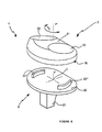
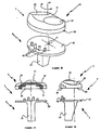
- Figure 1 is an exploded perspective view, illustrating the knee prosthesis according to the present invention.
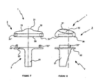
- Figures 2 and 3 are side views showing the knee prosthesis before fitting in place of the plastic tibial tray on the metal base.
- Figures 4 and 5 are views showing a first variant of the prosthesis knee according to the invention.
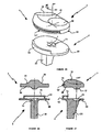
- Figures 6, 7 and 8 are views illustrating a second variant of the prosthesis knee, the metal base of which has two opposite guide lips.
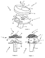
- Figures 9, 10 and 11 are views showing a third variant of the prosthesis knee whose metal base has a stud on its axis of rotation plastic tibial plateau retainer.
- Figures 12, 13 and 14 are views showing a fourth variant of the knee prosthesis whose metal base has on its axis of rotation a complementary stud for centering the plastic tibial plateau.
- Figures 15, 16 and 17 are views showing a fifth variant of the knee prosthesis which is provided with a notch for the passage of the ligament posterior crusader.
- Figures 18 to 24 are views illustrating variants of the knee prosthesis the metal base of which has two opposite guide lips, but of which one is carried by the center of rotation of the second.
- Figures 25 to 27 are views showing other variants of the prosthesis knee according to the present invention.
- Figures 28 and 29 are views illustrating guide means arranged at the periphery of the metal base and the tibial plateau of the knee prosthesis.
- Figures 30 to 32 are views showing guide means consisting of at least at least two vertical studs integral with the metal base which cooperate with a housing formed in the tibial plateau.
- FIGS. 1 to 3 show a knee prosthesis 1 comprising a base metallic 2 and a tibial plateau 3, while the femoral element is not represented.
- the metal base 2 consists of a horizontal disc 20 secured to one of its faces with an anchor rod 21 allowing the fixing of said base in a patient's shin.
- the horizontal disc 20 comprises, opposite the rod 21, guide means which consist of a lip 22 with an external profile in an arc.
- guide means which consist of a lip 22 with an external profile in an arc.
- the center of rotation C of the lip 22 is carried by the vertical axis YY 'tibial bone.
- the lip 22, extending vertically above the horizontal disc 20, has a central part 23 secured to each side of two vertical edges 24 and 25 of height less than that provided for said central part.
- the lip 22 is positioned on the horizontal disc 20 of the base metallic 2 at a certain distance from the center of rotation C.
- the tibial plateau 3 made of plastic, has a flat underside 30, arranged in a horizontal plane and parallel to that containing the disc 20 of the metal base.
- the tibial plateau 3 has an upper face 31 provided two tracks 32 and 33 with a concave profile, intended to receive the condyles of the femoral component not shown.
- the underside 30 is pierced with a housing 34 of the same radius of curvature than that provided for the lip 22 secured to the metal base 2.
- the housing 34 has cutouts 35 and 36 of larger dimensions which are intended to receive respectively the central part 23 and the edges side 24 and 25 of lip 22.
- the latter has dimensions greater than those provided for the lip 22 so that the tibial plateau 3 can slide freely in rotation around the center of rotation C of said lip 22 according to arrow F illustrated in FIG. 1.
- the arcuate or curved lip 22 is positioned in the front part of the metal base 2 and oriented in a substantially medio-lateral direction.
- FIGS. 4 and 5 a first variant of the knee prosthesis 1 has been shown. according to the present invention.
- the knee prosthesis 1 is identical to that described above, that is to say that it comprises a metal base 2 and a tibial plate made of material plastic 3.
- the metal base 2 has a difference from that above, the position of the guide means on the horizontal disc 20.
- the guide means consist of a lip 22 in an arc and whose profile is similar to that described above, but whose center of rotation C 'is offset from that C carried by the vertical bony axis of the tibia YY '.
- center of rotation C ' can be positioned anywhere, either on the horizontal disc 20, that is to say outside of it, while retaining the means of guidance on said horizontal disc and more particularly at a place,
- the lip 22 provided with its part central 23 and its side edges 24 and 25, enters the housing 34 formed in the underside 30 of the tibial plastic plate 3 for ensure a sliding in rotation of the latter on the metal base 2 and around the center of rotation C 'according to arrow F1 in FIG. 4.
- the arcuate or curved lip 22 is positioned in the front part of the metal base 2 and oriented in a substantially medio-lateral direction.
- the latter comprises a metal base 2 and a material plate plastic 3 similar to those described in FIG. 1, but whose means of guides are different to ensure better movement of the plate on the base.
- the metal base 2 provided with its horizontal disc 20 secured to its rod 21, includes guide means which consist of two lips opposite 22 'and 22 "in an arc.
- the lips 22' and 22" have the same center of curvature which merges with that of rotation C arranged on the axis vertical bone of the tibia YY '.
- the tibial plateau 3 has a flat underside 30 provided with two opposite housings 34 'and 34 "intended to receive the lips 22' and 22 "of the metal base 2.
- the housings 34 'and 34" have a radius of curvature identical to that of the 22 ′ and 22 ′′ lips.
- the knee prosthesis 1 is identical to that described in Figures 1 to 3, namely that it comprises a metal base 2 and a tibial plate made of material plastic 3.
- the metal base 2 has on its horizontal disc 20, and opposite its anchor rod 21, the guide means constituted by the lip 22 formed of central part 23 and two lateral edges 24 and 25.
- the horizontal disc 20 comprises, at the center of rotation C of the lip 22 which is carried by the vertical bony axis of the tibia YY ', a retaining stud 26 extending vertically above said disc 20.
- the retaining stud 26 constitutes an additional guiding means by means of guide formed by the lip 22.
- the stud 26 is positioned on the center of rotation C of the tibial plateau 3 on the metal base 2.
- the retaining stud 26 consists of a cylindrical finger 27 secured to a head 28 whose outer diameter is greater than that of said finger.
- the additional guide means or pad 26 is integral with the finger 27, 28 for prevent the tibial plateau 3 from lifting from the metal base 2 when the prosthesis is in motion.
- the tibial plateau 3 has on its underside 30 the housing 34 receiving the lip 22 and a notch 35 with inclined faces 36. This last cooperates during the establishment of the plate 3 on the base 2 with the retaining stud 26 of so that the head 28 is disposed above the inclined faces 36.
- the retaining stud 26 when it cooperates with the notch 35, makes it possible to prevent, during the sliding in rotation F4 of the tibial plateau 3 on the metal base 2, that said plate is raised under a tensile force.
- FIGS. 12 to 14 A fourth variant of the knee prosthesis 1 has been shown in FIGS. 12 to 14 according to the invention.
- the metal base 2 comprises opposite the lip 22, and at the level of the center of rotation C which is carried by the vertical bony axis of the tibia YY ', a stud of centering 29 extending vertically above the horizontal disc 20.
- the centering stud 29 extends vertically above the horizontal disc 20 of low height, constituting an additional guide means by means of guide formed by the lip 22.
- the centering stud 29 is constituted by a cylindrical finger of low height.
- the tibial plastic plate 3 comprises on its underside 30 and in face of the housing 34 a blind hole 37 intended to receive the centering stud 29 during the positioning of said plate on the metal base 2.
- the centering stud 29 makes it possible to materialize the center of rotation C of the lip 22 during the sliding in rotation of the tibial plateau 3 on the metal base 2.
- the knee prosthesis 1 illustrated in FIGS. 15 to 17 differs from that shown in Figures 1 to 3 only in the fact that the metal base 2 and the plate tibial plastic 3 have a notch 4 and 38 respectively for the passage of the posterior cruciate ligament.
- FIG 18 we have shown the knee prosthesis 1 provided with its base metal 2 and its tibial plateau 3.
- the metal base 2 has on its horizontal disc 20 and more particularly opposite the anchor rod 21, a lip 5 in an arc and of variable height. This last is scheduled from different profile from those constituting the lips described above.
- a second lip 6 At the level the center of rotation C of the lip 5 is provided a second lip 6 in an arc of circle.
- the lips 5 and 6 cooperate in housings not shown, but arranged on the face 30 of the tibial plateau 3 to allow guidance following a sliding in rotation of said plate around the center of rotation C, as is materialized by arrow F5.
- the arc-shaped or curved lip 5 is positioned in the anterior part of the metal base 2 and oriented in a substantially medio-lateral direction.
- the lip 6 constitutes an additional guiding means to the guiding means formed by the lip 5.
- the lip 6 is positioned on the center of rotation C of the tibial plateau 3 on the metal base 2.
- FIGs 19 to 21 there is shown a variant of the knee prosthesis 1 shown in Figure 18, namely that the lip 6 is integral with a flange 60 forming a kind of small tray arranged in a horizontal plane parallel to that containing the disc 20 of the metal base 2.
- the tibial plateau 3 has on its face 30 housings 7 and 8 intended for receive lips 5 and 6 respectively to allow sliding in rotation of the tibial plateau 3 on the metal base 2 around the center of rotation C and following arrow F5.
- the housing 7 has a profile substantially identical to that of the lip 5 and, at least, in an arc to guide, when moving, the tray tibial 3.
- the housing 8 has a profile substantially identical to the flange 60 of the additional guide means or lip 6 to guide, during its movements, the tibial plateau 3.
- the housing 8 is pierced with an internal groove 80 intended to receive the collar 60 of the lip 6 to effect a sort of snap-fitting of the tibial plateau 3 on the base 2, so that said plate cannot be raised during a tensile force.
- the lips 5 and 6 in an arc are curved in the same direction and following the same center of rotation C or C ', when the latter is offset by the vertical bone axis of the tibia YY '.
- the metal base 2 and the tibial plateau 3 can include the notches 4 and 38 respectively for the passage of the ligament posterior crusader.
- the knee prosthesis 1 has on its metal base 2 a first lip 5 ′ disposed at the outer periphery of the horizontal disc 20.
- the horizontal disc 20 is integral with another lip 9 in an arc of circle, but whose radius of curvature is reversed compared to that expected for the 5 'lip.
- the arc-shaped or curved lip 5 is positioned in the anterior part of the metal base 2 and oriented in a substantially medio-lateral direction.
- the lip 9 constitutes an additional guiding means to the guiding means formed by the lip 5 '.
- the lip 9 is positioned on the center of rotation C of the tibial plateau 3 on the metal base 2.
- the lip 9 has the same center of rotation C as that of the lip 5 ', but said center can be offset, depending on the configuration of the knee prosthesis, by the vertical bone axis of the tibia YY '.
- the lip 9 is integral with a flange 90 which will be seen more clearly below. function.
- the tibial plateau 3 has on its lower periphery, that is to say that included between the faces 30 and 31, a recess 10 receiving the lip 5 'during the setting place the tibial plateau 3 on the metal base 2.
- the lower face 30 is pierced with a housing 12 in which the lip 9 is snapped in, on the one hand to guide during sliding in rotation the plate 3 around its center C, and on the other hand retain said plate to prevent the latter from lifting off from the metal base 2.
- the knee prosthesis 1 comprises the metal base 2, the horizontal disc 20 has on its outer periphery a lip 13 in an arc of circle integral with a flange 14 directed towards the vertical bone axis of the shin YY '.
- the horizontal disc 20 is pierced at the center of rotation C of the lip 13 a bowl-shaped housing 15 constituting a guide means additional to the guide means formed by said lip 13.
- This last arched circular or curved is positioned in the front part of the base metallic 2 and oriented in a substantially medio-lateral direction.
- the lip 13 and the housing 15 may include a center of rotation C which is offset from the vertical bone axis of the tibia YY '.
- the tibial plateau 3 has on its outer periphery and between the faces 30 and 31, a recess 10 'in which is formed a horizontal groove 16 intended to receive the flange 14 of the lip 13 during the sliding rotation of the plate 3 on the metal base 2.
- the underside 30 is integral with a pin 17 with a conical profile capable of cooperating with the housing 15 formed in the horizontal disc 20 of the metal base 2.
- the lip 13 provided with its flange 14, the housing 15, the recess 10 'and its groove 16, and the tenon 17 constitute the means for guiding the tibial plateau 3 on the metal base 2 during the sliding rotation of said plate according to the arrow F5.
- the metal base 2 of the knee prosthesis 1 has on its horizontal disc 20 three peripheral lips 50, 51 and 52 extending vertically above said horizontal disc 20.
- the tibial plateau 3 has on its outer periphery three recesses peripherals 53, 54 and 55 intended to receive the lips 50, 51 and 52 to allow the guidance of said plate during its rotational sliding around the center of rotation of said lips which is identical for the three.
- the lip 51 in an arc or a curved shape is positioned in the anterior part of the metal base 2 and oriented in a substantially medio-lateral direction.
- the lips 50, 52 in an arc form a guide means additional to the guide means formed by the lip 51.
- the lips 50, 52 are positioned near the center of rotation C of the tibial plateau 3 on the base metallic 2.
- the metal base 2 of the knee prosthesis 1 has on its horizontal disc 20 vertical studs 18 arranged in an arc around a center of rotation C which can be either carried or offset from the vertical axis YY 'tibial bone.
- the studs 18 in an arc are positioned in the front part of the metal base 2 and oriented in a substantially medio-lateral direction.
- the tibial plateau 3 is identical to that described in FIGS. 1 to 3, that is to say that its lower face 30 comprises a housing 34 intended to receive the pads 18 for guiding during the sliding rotation of said plate by compared to the metal base 2.
- plastic tray 3 cannot slide in rotation on the metal base 2 only within the limits set by the difference of dimensions between the housing and the corresponding lip or stud, which allows prevent excess unwanted movement.
- a tray can be obtained by plastic 3 whose dimensions of the housing are identical to those of the lip or corresponding studs to prevent any deflection of said plate on the metal base 2. This allows the surgeon, depending on the operating case individuals, to return to a knee prosthesis system with a material plastic which is fixed on the metal base 2 without the need to change this last.
Abstract
Description
Claims (28)
- Prothèse de genou comportant une embase métallique solidaire d'une tige d'ancrage pour sa fixation dans le tibia d'un patient et un plateau tibial en matière plastique pouvant glisser librement sur ladite embase, caractérisée en ce que l'embase métallique (2) et le plateau tibial (3) sont pourvus de moyens de guidage (22, 22', 22", 26, 29, 5, 6, 5', 9, 50, 51, 52, 13, 15, 18 ; 34, 34', 34", 35, 37, 7, 8, 10, 12, 53, 54, 55, 10', 17) définissant un centre de rotation (C, C') qui peut être décalé de celui de l'axe osseux tibial (YY') de manière à permettre au plateau tibial (3) de glisser en rotation sur ladite embase, lesdits moyens de guidage étant positionnés à une certaine distance du centre de rotation (C, C').
- Prothèse de genou suivant la revendication 1, caractérisée en ce que les moyens de guidage sont constitués d'au moins une lèvre (22, 22', 22", 5, 6, 5', 9, 50, 51, 52, 13) en arc de cercle solidaire de l'embase métallique (2) et d'un logement (34, 34', 34", 7, 8, 10, 12, 53, 54, 55, 10') de même rayon de courbure pratiqué dans le plateau tibial (3) pour permettre à ce dernier de glisser en rotation autour du centre de rotation (C, C') de ladite lèvre.
- Prothèse de genou suivant la revendication 2, caractérisée en ce que les moyens de guidage sont constitués d'une lèvre (22, 5, 5', 51, 13) en arc de cercle qui est positionnée dans la partie antérieure de l'embase métallique (2) et orientée dans une direction sensiblement médio-latérale.
- Prothèse de genou suivant la revendication 1, caractérisée en ce que les moyens de guidage additionnels (26, 29, 6, 9, 15, 50, 52) sont positionnés sur ou à proximité du centre de rotation (C, C') du plateau tibial (3) sur l'embase métallique (2).
- Prothèse de genou suivant la revendication 4, caractérisée en ce que les moyens de guidage additionnels (26, 6, 9) sont solidaires d'un dispositif (28, 60, 90) permettant d'empêcher le plateau tibial (3) de se soulever de l'embase métallique (2).
- Prothèse de genou suivant la revendication 1, caractérisée en ce que les moyens de guidage sont constitués d'au moins deux plots (18) disposés en arc de cercle et définissant un centre de rotation (C, C'), et d'un logement (34) de même rayon de courbure ménagé dans le plateau tibial (3), lesdits plots étant positionnés dans la partie antérieure de l'embase métallique (2) et orientés dans une direction sensiblement médio-latérale.
- Prothèse de genou suivant la revendication 2, caractérisée en ce que l'embase métallique (2) comporte une lèvre (22) en arc de cercle présentant une partie centrale (23) solidaire de bords latéraux (24, 25) de plus faible hauteur que celle prévue pour ladite partie centrale, tandis que le plateau tibial (3) comprend sur sa face inférieure (30) un logement (34) en arc de cercle.
- Prothèse de genou suivant la revendication 2, caractérisée en ce que la lèvre (22, 22', 22", 5, 6, 5', 9, 50, 51, 52, 13) présente un centre de rotation (C) qui est porté par l'axe vertical osseux du tibia (YY'), tandis que ladite lèvre est à une certaine distance de son centre de rotation.
- Prothèse de genou suivant la revendication 2, caractérisée en ce que la lèvre (22, 22', 22", 5, 6, 5', 9, 50, 51, 52, 13) présente un centre de rotation (C') qui est décalé par rapport à l'axe vertical osseux du tibia (YY'), tandis que ladite lèvre est à une certaine distance de son centre de rotation.
- Prothèse de genou suivant la revendication 2, caractérisée en ce que l'embase métallique (2) comporte deux lèvres (22', 22") en arc de cercle, de hauteur constante et ayant un même centre de rotation (C, C'), tandis que le plateau tibial (3) comprend deux logements (34', 34") en arc de cercle.
- Prothèse de genou suivant la revendication 10, caractérisée en ce que les lèvres (22', 22") sont disposées à l'opposé l'une de l'autre, et présentent un même centre de rotation (C, C').
- Prothèse de genou suivant la revendication 1, caractérisée en ce que l'embase métallique (2) comporte en face de la lèvre (22) un plot de retenue (26) porté par un centre de rotation afin de coopérer avec une échancrure (35) ménagée dans le plateau tibial (3) pour empêcher ce dernier de se soulever par rapport à l'embase (2) lors du glissement en rotation dudit plateau autour de son centre de rotation.
- Prothèse de genou suivant la revendication 11, caractérisée en ce que le plot de retenue (26) est constitué d'un doigt cylindrique (27) solidaire d'une tête (28) de diamètre supérieur à celui prévu pour ledit doigt afin que ladite tête coopère avec des pans inclinés pratiqués dans l'échancrure (35).
- Prothèse de genou suivant la revendication 1, caractérisée en ce que l'embase métallique (2) comporte en face de la lèvre (22) un plot de centrage (29) porté par le centre de rotation (C, C') afin de coopérer avec un trou borgne (37) ménagé dans le plateau tibial (3) pour guider ce dernier par rapport à l'embase (2) lors du glissement en rotation dudit plateau autour de son centre de rotation.
- Prothèse de genou suivant la revendication 1, caractérisée en ce que l'embase métallique (2) et le plateau tibial (3) comportent respectivement une échancrure (4 et 38) pour le passage du ligament croisé postérieur.
- Prothèse de genou suivant la revendication 1, caractérisée en ce que l'embase métallique (2) comporte deux lèvres (5 et 6) en arc de cercle courbées dans le même sens et centrées autour du même centre de rotation (C, C'), tandis que le plateau tibial (3) comporte des logements (7 et 8) destinés à recevoir respectivement lesdites lèvres (5 et 6) pour permettre le glissement en rotation dudit plateau autour du centre de rotation (C, C').
- Prothèse de genou suivant la revendication 16, caractérisée en ce que la lèvre (6) est solidaire d'une collerette (60) qui coopère dans une rainure (80) du logement (8) pour empêcher le plateau tibial (3) de se soulever par rapport à l'embase métallique (2) lors du glissement en rotation dudit plateau autour du centre de rotation (C, C').
- Prothèse de genou suivant la revendication 1, caractérisée en ce que l'embase métallique (2) comporte deux lèvres (5' et 9) en arc de cercle de sens inversés et centrées autour du même centre de rotation (C, C'), tandis que le plateau tibial (3) comporte un élément (10) et un logement (12) destinés à recevoir respectivement lesdites lèvres (5' et 9) pour permettre le glissement en rotation dudit plateau autour du centre de rotation (C, C').
- Prothèse de genou suivant la revendication 18, caractérisée en ce que la lèvre (5') est disposée sur la périphérie exteme du disque horizontal (20) de l'embase métallique (2) afin de coopérer avec un évidement périphérique (10) du plateau tibial (3).
- Prothèse de genou suivant la revendication 18, caractérisée en ce que la lèvre (9) est décalée par rapport au centre de rotation (C, C') et comporte une collerette (90) qui vient s'encliqueter dans le logement (12) du plateau tibial (3) pour, d'une part guider lors du glissement en rotation le plateau (3) autour de son centre (C, C'), et d'autre part pour retenir ledit plateau afin que ce dernier ne se soulève pas de l'embase métallique (2).
- Prothèse de genou suivant la revendication 1, caractérisée en ce que l'embase métallique (2) comporte une lèvre périphérique (13) en arc de cercle solidaire d'une collerette (14) dirigée en direction de l'axe vertical osseux du tibia (YY') et un logement (15) disposé au niveau du centre de rotation (C, C'), tandis que le plateau tibial (3) présente sur sa périphérie externe un évidement (10') dans lequel est ménagée une rainure horizontale (16) destinée à recevoir la collerette (14) de ladite lèvre (13) et sur sa face inférieure (30) un tenon (17) qui coopère avec le logement (15).
- Prothèse de genou suivant la revendication 1, caractérisée en ce que l'embase métallique (2) comporte trois lèvres périphériques (50, 51, 52) s'étendant verticalement au-dessus du disque horizontal (20), tandis que le plateau tibial (3) présente sur sa périphérie externe trois évidements (53, 54, 55) destinés à recevoir respectivement lesdites lèvres (50, 51, 52) pour permettre le guidage dudit plateau lors de ses glissements en rotation autour du centre de rotation (C, C').
- Prothèse de genou suivant la revendication 6, caractérisée en ce que les plots (18) sont disposés en arc de cercle autour d'un centre de rotation (C, C'), tandis que le plateau tibial (3) présente un logement (34) destiné à recevoir lesdits plots.
- Prothèse de genou suivant la revendication 6, caractérisée en ce que les plots (18) présentent un centre de rotation (C) qui est porté par l'axe vertical osseux du tibia (YY'), tandis que ledit plot est à une certaine distance de son centre de rotation.
- Prothèse de genou suivant la revendication 6, caractérisée en ce que les plots (18) présentent un centre de rotation (C') qui est décalé par rapport à l'axe vertical osseux du tibia (YY'), tandis que ledit plot est à une certaine distance de son centre de rotation.
- Prothèse de genou suivant la revendication 1, caractérisée en ce que l'embase métallique (2) comporte au moins une lèvre ou plot (22, 22', 22", 26, 29, 5, 6, 5', 9, 50, 51, 52, 13, 15, 18) qui coopère avec un logement (34, 34', 34", 35, 7, 8, 10, 12, 53, 54, 55, 10', 17) du plateau tibial (3) de manière que ledit plateau puisse glisser en rotation sur l'embase métallique (2), que dans la limite fixée par la différence de dimensions entre ladite lèvre ou plot et ledit logement correspondant.
- Prothèse de genou suivant la revendication 26, caractérisée en ce que le débattement en rotation entre le plateau tibial (3) et l'embase métallique (2) est réduit à zéro lorsque les dimensions du logement (34, 34', 34", 7, 10, 10', 53, 54, 55) sont réalisées de manière à coopérer sans jeu avec la lèvre (22, 22', 22", 5, 5', 13, 50, 51, 52, 18).
- Prothèse de genou suivant la revendication 1, caractérisée en ce que la faible hauteur des moyens de guidage et de leurs positionnements antérieurs sur l'embase métallique (2) autorise un montage du plateau tibial (3) sur ladite embase par un abord strictement antérieur en ayant besoin de dégager ledit plateau vers le haut que de la hauteur desdits moyens de guidage.
Priority Applications (1)
| Application Number | Priority Date | Filing Date | Title |
|---|---|---|---|
| EP03015191A EP1350487A1 (fr) | 1997-09-23 | 1998-09-10 | Prothèse de genou à plateau rotatoire |
Applications Claiming Priority (2)
| Application Number | Priority Date | Filing Date | Title |
|---|---|---|---|
| FR9712042A FR2768613B1 (fr) | 1997-09-23 | 1997-09-23 | Prothese de genou a plateau rotatoire |
| FR9712042 | 1997-09-23 |
Related Child Applications (1)
| Application Number | Title | Priority Date | Filing Date |
|---|---|---|---|
| EP03015191A Division EP1350487A1 (fr) | 1997-09-23 | 1998-09-10 | Prothèse de genou à plateau rotatoire |
Publications (3)
| Publication Number | Publication Date |
|---|---|
| EP0903126A1 true EP0903126A1 (fr) | 1999-03-24 |
| EP0903126B1 EP0903126B1 (fr) | 2005-08-10 |
| EP0903126B8 EP0903126B8 (fr) | 2005-10-12 |
Family
ID=9511543
Family Applications (2)
| Application Number | Title | Priority Date | Filing Date |
|---|---|---|---|
| EP98420154A Expired - Lifetime EP0903126B8 (fr) | 1997-09-23 | 1998-09-10 | Prothèse de genou à plateau rotatoire |
| EP03015191A Withdrawn EP1350487A1 (fr) | 1997-09-23 | 1998-09-10 | Prothèse de genou à plateau rotatoire |
Family Applications After (1)
| Application Number | Title | Priority Date | Filing Date |
|---|---|---|---|
| EP03015191A Withdrawn EP1350487A1 (fr) | 1997-09-23 | 1998-09-10 | Prothèse de genou à plateau rotatoire |
Country Status (5)
| Country | Link |
|---|---|
| US (3) | US6299646B1 (fr) |
| EP (2) | EP0903126B8 (fr) |
| DE (1) | DE69831116T2 (fr) |
| ES (1) | ES2247669T3 (fr) |
| FR (1) | FR2768613B1 (fr) |
Cited By (12)
| Publication number | Priority date | Publication date | Assignee | Title |
|---|---|---|---|---|
| EP0978261A1 (fr) * | 1998-08-05 | 2000-02-09 | Biomedical Engineering Trust I | Prothèse d'articulation de genou avec empêchement de luxation |
| EP1064889A3 (fr) * | 1999-07-02 | 2002-01-09 | Bristol-Myers Squibb Company | Composant tibial de prothèse de genou à insert mobile |
| WO2006136760A2 (fr) * | 2005-06-24 | 2006-12-28 | Abbott Spine | Prothese de disque intervertebral |
| FR2901690A1 (fr) * | 2006-06-01 | 2007-12-07 | Evolutis Sa | Prothese totale du genou a glissement |
| EP1981439A2 (fr) * | 2006-01-20 | 2008-10-22 | Carl T. Hasselman | Procede de preparation au remplacement d'une articulation tibio-tarsienne, prothese d'articulation et appareil d'alignement de coupe a utiliser lors d'une procedure d'arthroplastie |
| EP2042132A1 (fr) * | 2007-09-27 | 2009-04-01 | Finsbury (Development) Limited | Prothèse du tibia comprenant un support mobile |
| US10188528B2 (en) | 2007-02-16 | 2019-01-29 | Ldr Medical | Interveterbral disc prosthesis insertion assemblies |
| US10226355B2 (en) | 2004-12-22 | 2019-03-12 | Ldr Medical | Intervertebral disc prosthesis |
| US10350088B2 (en) | 2005-06-29 | 2019-07-16 | Ldr Medical | Instrumentation and methods for inserting an intervertebral disc prosthesis |
| US10492919B2 (en) | 2005-09-23 | 2019-12-03 | Ldr Medical | Intervertebral disc prosthesis |
| US10603185B2 (en) | 2004-02-04 | 2020-03-31 | Ldr Medical | Intervertebral disc prosthesis |
| US10751187B2 (en) | 2007-06-08 | 2020-08-25 | Ldr Medical | Intersomatic cage, intervertebral prosthesis, anchoring device and implantation instruments |
Families Citing this family (120)
| Publication number | Priority date | Publication date | Assignee | Title |
|---|---|---|---|---|
| FR2768613B1 (fr) * | 1997-09-23 | 1999-12-17 | Tornier Sa | Prothese de genou a plateau rotatoire |
| FR2797178B1 (fr) * | 1999-08-05 | 2002-02-22 | Tornier Sa | Implant malleolaire pour prothese partielle ou totale de cheville et materiel ancillaire de pose d'un tel implant |
| US6558426B1 (en) | 2000-11-28 | 2003-05-06 | Medidea, Llc | Multiple-cam, posterior-stabilized knee prosthesis |
| US6719800B2 (en) | 2001-01-29 | 2004-04-13 | Zimmer Technology, Inc. | Constrained prosthetic knee with rotating bearing |
| FR2824261B1 (fr) | 2001-05-04 | 2004-05-28 | Ldr Medical | Prothese de disque intervertebral et procede et outils de mise en place |
| FR2826859B1 (fr) * | 2001-07-09 | 2003-09-19 | Tornier Sa | Ancillaire de pose d'un composant humeral de prothese de coude |
| FR2826860B1 (fr) * | 2001-07-09 | 2004-03-05 | Tornier Sa | Ancillaire de pose d'un composant cubital et/ou d'un composant radial de prothese de coude |
| FR2827500B1 (fr) * | 2001-07-17 | 2004-04-02 | Tornier Sa | Plaque d'osteosynthese de l'extremite superieure de l'humerus |
| US7179295B2 (en) * | 2001-10-05 | 2007-02-20 | Nebojsa Kovacevic | Prosthetic shock absorber |
| FR2830435B1 (fr) | 2001-10-10 | 2004-07-16 | Pierre Brugere | Implant tibial a plateau mobile pour prothese du genou |
| US6946001B2 (en) * | 2003-02-03 | 2005-09-20 | Zimmer Technology, Inc. | Mobile bearing unicompartmental knee |
| FR2846550B1 (fr) | 2002-11-05 | 2006-01-13 | Ldr Medical | Prothese de disque intervertebral |
| FR2848183B1 (fr) * | 2002-12-10 | 2006-01-27 | Tornier Sa | Procede de conditionnement sterile d'un implant prothetique en polyethylene |
| FR2850010B1 (fr) * | 2003-01-17 | 2005-12-02 | Tornier Sa | Ancillaire de pose d'un cotyle prothetique pour une prothese de hanche |
| US7033397B2 (en) * | 2003-02-03 | 2006-04-25 | Zimmer Technology, Inc. | Mobile bearing unicondylar tibial knee prosthesis |
| WO2004069105A1 (fr) * | 2003-02-04 | 2004-08-19 | Zimmer Austin, Inc. | Systeme de plaque de base/insert tibial rotatif/non rotatif |
| US8388624B2 (en) | 2003-02-24 | 2013-03-05 | Arthrosurface Incorporated | Trochlear resurfacing system and method |
| US7887544B2 (en) | 2003-03-10 | 2011-02-15 | Tornier Sas | Ancillary tool for positioning a glenoid implant |
| FR2854792B1 (fr) * | 2003-05-12 | 2005-09-09 | Tornier Sa | Jeu d'elements prothetiques pour un ensemble prothetique tibial |
| FR2855397B1 (fr) | 2003-05-28 | 2005-07-15 | Tornier Sa | Prothese de coude |
| US7559931B2 (en) | 2003-06-09 | 2009-07-14 | OrthAlign, Inc. | Surgical orientation system and method |
| CN1845713B (zh) * | 2003-07-17 | 2010-06-02 | 精密技术公司 | 活动支承件膝盖假体 |
| US7708782B2 (en) * | 2003-07-17 | 2010-05-04 | Exactech, Inc. | Mobile bearing knee prosthesis |
| US7534270B2 (en) * | 2003-09-03 | 2009-05-19 | Integra Lifesciences Corporation | Modular total ankle prosthesis apparatuses and methods |
| US20050055100A1 (en) * | 2003-09-08 | 2005-03-10 | Lewis Ralph Harrison | Total knee replacement for dogs |
| FR2863865B1 (fr) | 2003-12-19 | 2006-10-06 | Tornier Sa | Prothese d'epaule ou de hanche et son procede de montage |
| FR2865629B1 (fr) | 2004-02-04 | 2007-01-26 | Ldr Medical | Prothese de disque intervertebral |
| FR2865928B1 (fr) | 2004-02-10 | 2006-03-17 | Tornier Sa | Dispositif chirurgical d'implantation d'une prothese totale de hanche |
| EP1574185B1 (fr) * | 2004-03-09 | 2012-05-23 | Zimmer Technology, Inc. | Composant tibial de genou avec un roulement mobile |
| FR2869528B1 (fr) | 2004-04-28 | 2007-02-02 | Ldr Medical | Prothese de disque intervertebral |
| US7678150B2 (en) | 2004-06-15 | 2010-03-16 | Tornier Sas | Total shoulder prosthesis of an inverted type |
| US8303665B2 (en) | 2004-06-15 | 2012-11-06 | Tornier Sas | Glenoidal component, set of such components and shoulder prosthesis incorporating such a glenoidal component |
| FR2871368B1 (fr) | 2004-06-15 | 2006-08-25 | Tornier Sas | Jeu de composants humeraux pour prothese totale d'epaule |
| FR2871371B1 (fr) | 2004-06-15 | 2007-04-06 | Tornier Sas | Composant glenoidien de prothese d'epaule, jeu d'elements constitutifs d'un tel composant et prothese totale d'epaule incorporant un tel composant |
| FR2872025B1 (fr) * | 2004-06-28 | 2006-08-25 | Tornier Sas | Prothese d'epaule ou de hanche |
| EP1809209A2 (fr) * | 2004-08-19 | 2007-07-25 | Kinetikos Medical Incorporated | Appareils, systemes et procedes modulaires de prothese totale de la cheville, et systemes et procedes pour la resection osseuse et l'implantation prothetique |
| FR2881340B1 (fr) * | 2005-02-01 | 2008-01-11 | Tornier Sas | Clou humeral |
| FR2884407B1 (fr) * | 2005-04-13 | 2007-05-25 | Tornier Sas | Dispositif chirurgical d'implantation d'une prothese partielle ou totale du genou |
| FR2884408B1 (fr) * | 2005-04-13 | 2007-05-25 | Tornier Sas | Dispositif chirurgical d'implantation d'une prothese partielle ou totale de genou |
| US7468077B2 (en) * | 2005-08-02 | 2008-12-23 | Tornier Sas | Patellar retractor and method of surgical procedure on knee |
| AU2006308865B2 (en) * | 2005-10-31 | 2012-10-25 | Depuy Products, Inc. | Modular fixed and mobile bearing prosthesis system |
| FR2893838B1 (fr) | 2005-11-30 | 2008-08-08 | Ldr Medical Soc Par Actions Si | Prothese de disque intervertebral et instrumentation d'insertion de la prothese entre les vertebres |
| FR2896404B1 (fr) | 2006-01-24 | 2008-02-29 | Tornier Sas | Ensemble d'instrumentation chirurgicale pour poser une prothese de cheville |
| FR2896684B1 (fr) * | 2006-02-01 | 2008-09-26 | Tornier Soc Par Actions Simplifiee | Implant tibial a tige offset |
| CN104207863B (zh) * | 2006-03-21 | 2018-09-07 | 德普伊爱尔兰无限公司 | 引入力矩的全关节置换假体 |
| AU2006340364B2 (en) * | 2006-03-21 | 2011-04-28 | Komistek, Richard D | Moment induced total arthroplasty prosthetic |
| FR2899790B1 (fr) | 2006-04-13 | 2008-06-13 | Tornier Sas | Composant glenoidien pour prothese totale d'epaule, jeu de tels composants, et prothese totale d'epaule comprenant un tel composant |
| FR2900045B1 (fr) | 2006-04-21 | 2009-01-16 | Tornier Sas | Prothese d'epaule ou de hanche |
| US20110213375A1 (en) | 2006-07-17 | 2011-09-01 | Arthrosurface, Inc. | Tibial Resurfacing System and Method |
| US7740662B2 (en) * | 2006-10-13 | 2010-06-22 | Depuy Products, Inc. | Mobile/fixed prosthetic knee systems |
| FR2906999B1 (fr) | 2006-10-13 | 2009-06-05 | Tornier Sas | Ensemble prothetique de cheville |
| US20080091272A1 (en) * | 2006-10-13 | 2008-04-17 | Aram Luke J | Mobile/fixed prosthetic knee systems |
| US20080091273A1 (en) * | 2006-10-13 | 2008-04-17 | Hazebrouck Stephen A | Mobile/fixed prosthetic knee systems |
| US20080114463A1 (en) * | 2006-10-13 | 2008-05-15 | Auger Daniel D | Mobile/fixed prosthetic knee systems |
| US8308812B2 (en) | 2006-11-07 | 2012-11-13 | Biomedflex, Llc | Prosthetic joint assembly and joint member therefor |
| US8070823B2 (en) * | 2006-11-07 | 2011-12-06 | Biomedflex Llc | Prosthetic ball-and-socket joint |
| US8029574B2 (en) * | 2006-11-07 | 2011-10-04 | Biomedflex Llc | Prosthetic knee joint |
| US9005307B2 (en) | 2006-11-07 | 2015-04-14 | Biomedflex, Llc | Prosthetic ball-and-socket joint |
| US8512413B2 (en) | 2006-11-07 | 2013-08-20 | Biomedflex, Llc | Prosthetic knee joint |
| CA2668692C (fr) | 2006-11-07 | 2013-06-18 | Biomedflex, Llc | Implants medicaux |
| US20110166671A1 (en) | 2006-11-07 | 2011-07-07 | Kellar Franz W | Prosthetic joint |
| US9358029B2 (en) | 2006-12-11 | 2016-06-07 | Arthrosurface Incorporated | Retrograde resection apparatus and method |
| US8715359B2 (en) | 2009-10-30 | 2014-05-06 | Depuy (Ireland) | Prosthesis for cemented fixation and method for making the prosthesis |
| US8470047B2 (en) * | 2007-09-25 | 2013-06-25 | Depuy (Ireland) | Fixed-bearing knee prosthesis |
| US8128703B2 (en) * | 2007-09-28 | 2012-03-06 | Depuy Products, Inc. | Fixed-bearing knee prosthesis having interchangeable components |
| US20110035017A1 (en) * | 2007-09-25 | 2011-02-10 | Depuy Products, Inc. | Prosthesis with cut-off pegs and surgical method |
| US7628818B2 (en) * | 2007-09-28 | 2009-12-08 | Depuy Products, Inc. | Fixed-bearing knee prosthesis having interchangeable components |
| US8632600B2 (en) | 2007-09-25 | 2014-01-21 | Depuy (Ireland) | Prosthesis with modular extensions |
| US9204967B2 (en) * | 2007-09-28 | 2015-12-08 | Depuy (Ireland) | Fixed-bearing knee prosthesis having interchangeable components |
| ES2531704T3 (es) | 2007-11-02 | 2015-03-18 | Biomet Uk Limited | Prótesis para la simulación de cinemática natural |
| US8828086B2 (en) | 2008-06-30 | 2014-09-09 | Depuy (Ireland) | Orthopaedic femoral component having controlled condylar curvature |
| US8236061B2 (en) | 2008-06-30 | 2012-08-07 | Depuy Products, Inc. | Orthopaedic knee prosthesis having controlled condylar curvature |
| US8206451B2 (en) | 2008-06-30 | 2012-06-26 | Depuy Products, Inc. | Posterior stabilized orthopaedic prosthesis |
| US9168145B2 (en) | 2008-06-30 | 2015-10-27 | Depuy (Ireland) | Posterior stabilized orthopaedic knee prosthesis having controlled condylar curvature |
| US8192498B2 (en) | 2008-06-30 | 2012-06-05 | Depuy Products, Inc. | Posterior cructiate-retaining orthopaedic knee prosthesis having controlled condylar curvature |
| US9119723B2 (en) | 2008-06-30 | 2015-09-01 | Depuy (Ireland) | Posterior stabilized orthopaedic prosthesis assembly |
| US8187335B2 (en) | 2008-06-30 | 2012-05-29 | Depuy Products, Inc. | Posterior stabilized orthopaedic knee prosthesis having controlled condylar curvature |
| US7981159B2 (en) * | 2008-07-16 | 2011-07-19 | Depuy Products, Inc. | Antero-posterior placement of axis of rotation for a rotating platform |
| US8202323B2 (en) * | 2008-07-16 | 2012-06-19 | Depuy Products, Inc. | Knee prostheses with enhanced kinematics |
| EP2344078B1 (fr) | 2008-07-24 | 2018-04-18 | OrthAlign, Inc. | Systèmes pour le remplacement d'une articulation |
| EP2358310B1 (fr) | 2008-09-10 | 2019-07-31 | OrthAlign, Inc. | Systèmes de chirurgie de la hanche |
| WO2010056962A1 (fr) * | 2008-11-14 | 2010-05-20 | Barker Bretell | Prise tibiale mobile transitoirement |
| WO2016154393A1 (fr) | 2009-04-17 | 2016-09-29 | Arthrosurface Incorporated | Système de réparation de glénoïde et ses méthodes d'utilisation |
| WO2010121250A1 (fr) | 2009-04-17 | 2010-10-21 | Arthrosurface Incorporated | Système et procédé de re-surfaçage de glénoïde |
| US8915965B2 (en) | 2009-05-07 | 2014-12-23 | Depuy (Ireland) | Anterior stabilized knee implant |
| US8118815B2 (en) | 2009-07-24 | 2012-02-21 | OrthAlign, Inc. | Systems and methods for joint replacement |
| US10869771B2 (en) | 2009-07-24 | 2020-12-22 | OrthAlign, Inc. | Systems and methods for joint replacement |
| US9011547B2 (en) | 2010-01-21 | 2015-04-21 | Depuy (Ireland) | Knee prosthesis system |
| EP3470020A3 (fr) | 2010-01-29 | 2019-09-18 | Smith & Nephew, Inc. | Prothèse de genou à préservation des deux ligaments croisés |
| AU2011261509B2 (en) * | 2010-06-01 | 2016-03-10 | Smith & Nephew, Inc | Orthopaedic implant system and fasteners for use therein |
| FR2966343B1 (fr) | 2010-10-22 | 2012-12-07 | Tornier Sa | Jeu de composants glenoidiens d'une prothese d'epaule |
| US8617250B2 (en) | 2011-06-17 | 2013-12-31 | Biomet Manufacturing, Llc | Revision knee tibial locking mechanism |
| US9814584B2 (en) | 2011-09-28 | 2017-11-14 | Depuy Ireland Unlimited Company | Fixed-bearing knee prosthesis having a locking mechanism with a concave-to-convex mating interface |
| US9421106B2 (en) | 2011-12-07 | 2016-08-23 | Howmedica Osteonics Corp. | Reverse shoulder baseplate with alignment guide for glenosphere |
| WO2013096746A1 (fr) | 2011-12-22 | 2013-06-27 | Arthrosurface Incorporated | Système et procédé pour une fixation osseuse |
| JP2015517361A (ja) | 2012-05-18 | 2015-06-22 | オースアライン・インコーポレイテッド | 膝関節形成術用の装置および方法 |
| US8663334B2 (en) | 2012-05-31 | 2014-03-04 | Howmedica Osteonics Corp. | Lateral entry insert for cup trial |
| US8906102B2 (en) | 2012-05-31 | 2014-12-09 | Howmedica Osteonics Corp. | Lateral entry insert for cup trial |
| DE112013003358T5 (de) | 2012-07-03 | 2015-03-19 | Arthrosurface, Inc. | System und Verfahren für Gelenkoberflächenersatz und -reparatur |
| US9649160B2 (en) | 2012-08-14 | 2017-05-16 | OrthAlign, Inc. | Hip replacement navigation system and method |
| FR2994644B1 (fr) * | 2012-08-24 | 2014-08-29 | Anatomic | Embase tibiale prothetique et insert tibial prothetique destine a etre immobilise sur une telle embase tibiale prothetique |
| GB2512609A (en) * | 2013-04-03 | 2014-10-08 | Fitzbionics Ltd | Total knee replacement prosthesis assembly |
| US9492200B2 (en) | 2013-04-16 | 2016-11-15 | Arthrosurface Incorporated | Suture system and method |
| US20150250472A1 (en) | 2014-03-07 | 2015-09-10 | Arthrosurface Incorporated | Delivery System for Articular Surface Implant |
| US10624748B2 (en) | 2014-03-07 | 2020-04-21 | Arthrosurface Incorporated | System and method for repairing articular surfaces |
| US11607319B2 (en) | 2014-03-07 | 2023-03-21 | Arthrosurface Incorporated | System and method for repairing articular surfaces |
| US9610168B2 (en) | 2014-05-12 | 2017-04-04 | Integra Lifesciences Corporation | Total ankle replacement prosthesis |
| US10575968B2 (en) | 2014-05-16 | 2020-03-03 | Howmedica Osteonics Corp. | Guides for fracture system |
| US9681960B2 (en) | 2014-05-16 | 2017-06-20 | Howmedica Osteonics Corp. | Guides for fracture system |
| US10363149B2 (en) | 2015-02-20 | 2019-07-30 | OrthAlign, Inc. | Hip replacement navigation system and method |
| US10390972B2 (en) | 2016-01-15 | 2019-08-27 | Howmedica Osteonics Corp. | Humeral trial adaptor |
| US10179052B2 (en) | 2016-07-28 | 2019-01-15 | Depuy Ireland Unlimited Company | Total knee implant prosthesis assembly and method |
| CN106264801A (zh) * | 2016-08-03 | 2017-01-04 | 嘉思特华剑医疗器材(天津)有限公司 | 解剖型不对称双平台膝关节假体 |
| CA3056382A1 (fr) | 2017-03-14 | 2018-09-20 | OrthAlign, Inc. | Systemes et procedes de guidage pour un remplacement de hanche |
| JP7344122B2 (ja) | 2017-03-14 | 2023-09-13 | オースアライン・インコーポレイテッド | 軟部組織の測定およびバランシングを行うシステムおよび方法 |
| CA3108761A1 (fr) | 2017-08-04 | 2019-02-07 | Arthrosurface Incorporated | Implant de surface articulaire a composants multiples |
| US20210137692A1 (en) * | 2018-01-17 | 2021-05-13 | Matthew Budge | Reverse shoulder prosthesis |
| US10898338B1 (en) * | 2018-01-17 | 2021-01-26 | Matthew Budge | Reverse shoulder prosthesis |
| US11478358B2 (en) | 2019-03-12 | 2022-10-25 | Arthrosurface Incorporated | Humeral and glenoid articular surface implant systems and methods |
| CN114010375B (zh) * | 2022-01-06 | 2022-06-14 | 北京爱康宜诚医疗器材有限公司 | 膝关节假体及膝关节假体的加工方法 |
Citations (8)
| Publication number | Priority date | Publication date | Assignee | Title |
|---|---|---|---|---|
| GB2061730A (en) * | 1979-10-26 | 1981-05-20 | Polyzoides A J | Endoprosthetic bone joint devices |
| US4728332A (en) * | 1984-11-28 | 1988-03-01 | Albrektsson Bjoern | Artificial menisco-tibial joint |
| EP0346183A1 (fr) * | 1988-05-31 | 1989-12-13 | Societe Civile D'etude Et De Recherche De Nouvelles Protheses (Scernp) | Prothèse à glissement pour le genou |
| US5282868A (en) * | 1991-06-17 | 1994-02-01 | Andre Bahler | Prosthetic arrangement for a complex joint, especially knee joint |
| EP0634156A2 (fr) * | 1993-07-16 | 1995-01-18 | Peter Stanley Walker | Prothèse de remplacement du genou |
| FR2707871A1 (fr) * | 1993-07-22 | 1995-01-27 | Serf | Prothèse bicondylienne du genou du type à glissement. |
| FR2735017A1 (fr) * | 1995-06-08 | 1996-12-13 | Groupe Lepine | Prothese de genou a plateau mobile |
| GB2312377A (en) * | 1996-04-24 | 1997-10-29 | Roozbeh Shirandami | Three part prosthetic knee joint with anterior posterior sliding action |
Family Cites Families (69)
| Publication number | Priority date | Publication date | Assignee | Title |
|---|---|---|---|---|
| GB8432267D0 (en) * | 1984-12-20 | 1985-01-30 | Thackray C F Ltd | Knee prosthesis |
| US4714474A (en) * | 1986-05-12 | 1987-12-22 | Dow Corning Wright Corporation | Tibial knee joint prosthesis with removable articulating surface insert |
| AU9089891A (en) * | 1990-11-14 | 1992-06-11 | Arch Development Corporation | Improved floating bearing prosthetic knee |
| FR2669213A1 (fr) * | 1990-11-19 | 1992-05-22 | Tornier Sa | Prothese femorale partiellement cimentee. |
| FR2681240A1 (fr) * | 1991-09-12 | 1993-03-19 | Tornier Sa | Prothese totale de poignet. |
| FR2684290B1 (fr) * | 1991-11-29 | 1994-01-21 | Tornier Ets | Prothese du genou. |
| FR2685633B1 (fr) * | 1991-12-27 | 1998-02-27 | Tornier Sa | Prothese humerale modulaire. |
| FR2691357A1 (fr) * | 1992-05-25 | 1993-11-26 | Tornier Sa | Prothèse totale pour l'articulation métacarpo-phalangienne. |
| US5344460A (en) * | 1992-10-30 | 1994-09-06 | Encore Orthopedics, Inc. | Prosthesis system |
| US5658342A (en) * | 1992-11-16 | 1997-08-19 | Arch Development | Stabilized prosthetic knee |
| FR2703240B1 (fr) * | 1993-03-30 | 1995-06-02 | Tornier Sa | Prothèse cotyloïdienne élastiquement déformable. |
| FR2705226B1 (fr) * | 1993-05-17 | 1995-07-07 | Tornier Sa | Fixateur de rachis pour le maintien d'une colonne vertébrale. |
| FR2709412B1 (fr) * | 1993-09-01 | 1995-11-24 | Tornier Sa | Vis pour fixateur lombo-sacré. |
| FR2711505B1 (fr) * | 1993-10-25 | 1995-12-29 | Tornier Sa | Dispositif de synthèse des fractures de l'extrémité supérieure du fémur. |
| FR2724553B1 (fr) * | 1994-09-15 | 1996-12-20 | Tornier Sa | Fixateur externe ou interne destine a la reparation des fractures ou des arthroplasties du squelette |
| FR2727002B1 (fr) * | 1994-11-18 | 1997-01-03 | Tornier Sa | Prothese humerale a sphere |
| FR2728159B1 (fr) * | 1994-12-16 | 1997-06-27 | Tornier Sa | Prothese discale elastique |
| US5683468A (en) * | 1995-03-13 | 1997-11-04 | Pappas; Michael J. | Mobile bearing total joint replacement |
| FR2735356B1 (fr) * | 1995-06-16 | 1997-11-28 | Tornier Sa | Implant cotyloidien destine notamment a la cavite articulaire iliaque |
| FR2741796B1 (fr) * | 1995-11-30 | 1998-03-27 | Tornier Sa | Dispositif pour la fixation d'une prothese et notamment d'une prothese glenoidienne de l'omoplate |
| FR2743716B1 (fr) * | 1996-01-23 | 1998-04-10 | Tornier Sa | Prothese tibiale |
| US5871543A (en) * | 1996-02-23 | 1999-02-16 | Hofmann; Aaron A. | Tibial prosthesis with mobile bearing member |
| FR2747302B1 (fr) * | 1996-04-11 | 1998-09-11 | Tornier Sa | Prothese de cheville |
| GB9611060D0 (en) * | 1996-05-28 | 1996-07-31 | Howmedica | Tibial element for a replacment knee prosthesis |
| FR2750037B1 (fr) * | 1996-06-25 | 1998-11-27 | Tornier Sa | Prothese d'epaule monobloc |
| FR2751868B1 (fr) * | 1996-08-02 | 1999-04-16 | Tornier Sa | Prothese ajouree de l'extremite superieure de l'humerus |
| FR2758455B1 (fr) * | 1997-01-23 | 1999-08-06 | Tornier Sa | Prothese totale de coude |
| FR2760353B1 (fr) * | 1997-03-10 | 1999-07-02 | Tornier Sa | Prothese de cheville |
| FR2768330B1 (fr) * | 1997-09-12 | 2000-01-21 | Tornier Sa | Prothese humeral a sphere indexee |
| FR2768613B1 (fr) * | 1997-09-23 | 1999-12-17 | Tornier Sa | Prothese de genou a plateau rotatoire |
| US5951603A (en) * | 1997-09-25 | 1999-09-14 | Johnson & Johnson Professional, Inc. | Rotatable joint prosthesis with axial securement |
| FR2768922B1 (fr) * | 1997-10-01 | 2000-01-14 | Tornier Sa | Prothese destinee a etre ancree dans un os long |
| FR2769494B1 (fr) * | 1997-10-14 | 1999-12-31 | Michel Timoteo | Piece femorale pour prothese de genou |
| FR2769495B1 (fr) * | 1997-10-14 | 1999-12-31 | Michel Timoteo | Prothese de genou |
| FR2772259B1 (fr) * | 1997-12-12 | 2000-03-03 | Tornier Sa | Perfectionnements apportes aux protheses totales de genou comportant un element femoral et un plateau tibial |
| FR2775586B1 (fr) * | 1998-03-03 | 2000-06-30 | Tornier Sa | Implant acetabulaire ou cotyloidien modulaire |
| FR2777442B1 (fr) * | 1998-04-21 | 2000-07-28 | Tornier Sa | Ancre de suture a expansion reversible |
| FR2777447B1 (fr) * | 1998-04-21 | 2000-07-28 | Tornier Sa | Dispositif de fixation reversible pour la mise en place d'un implant dans l'os |
| FR2777443B1 (fr) * | 1998-04-21 | 2000-06-30 | Tornier Sa | Ancillaire pour la mise en place et le retrait d'un implant et plus particulierement d'une ancre de suture |
| GB9823759D0 (en) * | 1998-10-31 | 1998-12-23 | Rota Limited | A safety device |
| FR2793404B1 (fr) * | 1999-05-14 | 2001-09-14 | Tornier Sa | Prothese de coude |
| FR2794641B1 (fr) * | 1999-06-09 | 2001-11-23 | Tornier Sa | Prothese humerale |
| FR2797178B1 (fr) * | 1999-08-05 | 2002-02-22 | Tornier Sa | Implant malleolaire pour prothese partielle ou totale de cheville et materiel ancillaire de pose d'un tel implant |
| FR2826860B1 (fr) * | 2001-07-09 | 2004-03-05 | Tornier Sa | Ancillaire de pose d'un composant cubital et/ou d'un composant radial de prothese de coude |
| FR2826859B1 (fr) * | 2001-07-09 | 2003-09-19 | Tornier Sa | Ancillaire de pose d'un composant humeral de prothese de coude |
| FR2827500B1 (fr) * | 2001-07-17 | 2004-04-02 | Tornier Sa | Plaque d'osteosynthese de l'extremite superieure de l'humerus |
| FR2831426B1 (fr) * | 2001-10-30 | 2004-07-16 | Tornier Sa | Implant rotulien et prothese de genou incorporant un tel implant |
| FR2835425B1 (fr) * | 2002-02-04 | 2004-04-09 | Tornier Sa | Element prothetique comprenant deux composants et procede d'assemblage d'un tel element prothetique |
| FR2836039B1 (fr) * | 2002-02-15 | 2004-10-01 | Tornier Sa | Composant glenoidien de prothese d'epaule et prothese totale d'epaule incorporant un tel composant |
| FR2841768B1 (fr) * | 2002-07-05 | 2005-05-06 | Tornier Sa | Prothese d'epaule ou de hanche facilitant l'abduction |
| FR2848183B1 (fr) * | 2002-12-10 | 2006-01-27 | Tornier Sa | Procede de conditionnement sterile d'un implant prothetique en polyethylene |
| FR2850010B1 (fr) * | 2003-01-17 | 2005-12-02 | Tornier Sa | Ancillaire de pose d'un cotyle prothetique pour une prothese de hanche |
| US7887544B2 (en) * | 2003-03-10 | 2011-02-15 | Tornier Sas | Ancillary tool for positioning a glenoid implant |
| FR2854792B1 (fr) * | 2003-05-12 | 2005-09-09 | Tornier Sa | Jeu d'elements prothetiques pour un ensemble prothetique tibial |
| FR2855397B1 (fr) * | 2003-05-28 | 2005-07-15 | Tornier Sa | Prothese de coude |
| FR2859099B1 (fr) * | 2003-08-25 | 2006-01-06 | Tornier Sa | Composant glenoidien de prothese d'epaule et prothese totale d'epaule incorporant un tel composant |
| FR2863865B1 (fr) * | 2003-12-19 | 2006-10-06 | Tornier Sa | Prothese d'epaule ou de hanche et son procede de montage |
| FR2865928B1 (fr) * | 2004-02-10 | 2006-03-17 | Tornier Sa | Dispositif chirurgical d'implantation d'une prothese totale de hanche |
| FR2871371B1 (fr) * | 2004-06-15 | 2007-04-06 | Tornier Sas | Composant glenoidien de prothese d'epaule, jeu d'elements constitutifs d'un tel composant et prothese totale d'epaule incorporant un tel composant |
| US7678150B2 (en) * | 2004-06-15 | 2010-03-16 | Tornier Sas | Total shoulder prosthesis of an inverted type |
| US8303665B2 (en) * | 2004-06-15 | 2012-11-06 | Tornier Sas | Glenoidal component, set of such components and shoulder prosthesis incorporating such a glenoidal component |
| FR2871368B1 (fr) * | 2004-06-15 | 2006-08-25 | Tornier Sas | Jeu de composants humeraux pour prothese totale d'epaule |
| FR2872025B1 (fr) * | 2004-06-28 | 2006-08-25 | Tornier Sas | Prothese d'epaule ou de hanche |
| FR2881340B1 (fr) * | 2005-02-01 | 2008-01-11 | Tornier Sas | Clou humeral |
| FR2884408B1 (fr) * | 2005-04-13 | 2007-05-25 | Tornier Sas | Dispositif chirurgical d'implantation d'une prothese partielle ou totale de genou |
| FR2884407B1 (fr) * | 2005-04-13 | 2007-05-25 | Tornier Sas | Dispositif chirurgical d'implantation d'une prothese partielle ou totale du genou |
| US7468077B2 (en) * | 2005-08-02 | 2008-12-23 | Tornier Sas | Patellar retractor and method of surgical procedure on knee |
| FR2896404B1 (fr) * | 2006-01-24 | 2008-02-29 | Tornier Sas | Ensemble d'instrumentation chirurgicale pour poser une prothese de cheville |
| FR2896684B1 (fr) * | 2006-02-01 | 2008-09-26 | Tornier Soc Par Actions Simplifiee | Implant tibial a tige offset |
-
1997
- 1997-09-23 FR FR9712042A patent/FR2768613B1/fr not_active Expired - Fee Related
-
1998
- 1998-09-10 DE DE69831116T patent/DE69831116T2/de not_active Expired - Lifetime
- 1998-09-10 EP EP98420154A patent/EP0903126B8/fr not_active Expired - Lifetime
- 1998-09-10 EP EP03015191A patent/EP1350487A1/fr not_active Withdrawn
- 1998-09-10 ES ES98420154T patent/ES2247669T3/es not_active Expired - Lifetime
- 1998-09-23 US US09/158,791 patent/US6299646B1/en not_active Expired - Lifetime
-
2001
- 2001-04-12 US US09/832,874 patent/US20010014827A1/en not_active Abandoned
-
2005
- 2005-06-03 US US11/143,742 patent/US7951204B2/en not_active Expired - Fee Related
Patent Citations (8)
| Publication number | Priority date | Publication date | Assignee | Title |
|---|---|---|---|---|
| GB2061730A (en) * | 1979-10-26 | 1981-05-20 | Polyzoides A J | Endoprosthetic bone joint devices |
| US4728332A (en) * | 1984-11-28 | 1988-03-01 | Albrektsson Bjoern | Artificial menisco-tibial joint |
| EP0346183A1 (fr) * | 1988-05-31 | 1989-12-13 | Societe Civile D'etude Et De Recherche De Nouvelles Protheses (Scernp) | Prothèse à glissement pour le genou |
| US5282868A (en) * | 1991-06-17 | 1994-02-01 | Andre Bahler | Prosthetic arrangement for a complex joint, especially knee joint |
| EP0634156A2 (fr) * | 1993-07-16 | 1995-01-18 | Peter Stanley Walker | Prothèse de remplacement du genou |
| FR2707871A1 (fr) * | 1993-07-22 | 1995-01-27 | Serf | Prothèse bicondylienne du genou du type à glissement. |
| FR2735017A1 (fr) * | 1995-06-08 | 1996-12-13 | Groupe Lepine | Prothese de genou a plateau mobile |
| GB2312377A (en) * | 1996-04-24 | 1997-10-29 | Roozbeh Shirandami | Three part prosthetic knee joint with anterior posterior sliding action |
Cited By (20)
| Publication number | Priority date | Publication date | Assignee | Title |
|---|---|---|---|---|
| EP0978261A1 (fr) * | 1998-08-05 | 2000-02-09 | Biomedical Engineering Trust I | Prothèse d'articulation de genou avec empêchement de luxation |
| EP1064889A3 (fr) * | 1999-07-02 | 2002-01-09 | Bristol-Myers Squibb Company | Composant tibial de prothèse de genou à insert mobile |
| AU771790B2 (en) * | 1999-07-02 | 2004-04-01 | Zimmer Technology, Inc. | Tibial knee component with a mobile bearing |
| EP1413264A2 (fr) * | 1999-07-02 | 2004-04-28 | Bristol-Myers Squibb Company | Composant tibial de prothèse de genou à insert mobile |
| EP1413264A3 (fr) * | 1999-07-02 | 2005-01-19 | Bristol-Myers Squibb Company | Composant tibial de prothèse de genou à insert mobile |
| US11957598B2 (en) | 2004-02-04 | 2024-04-16 | Ldr Medical | Intervertebral disc prosthesis |
| US10603185B2 (en) | 2004-02-04 | 2020-03-31 | Ldr Medical | Intervertebral disc prosthesis |
| US10226355B2 (en) | 2004-12-22 | 2019-03-12 | Ldr Medical | Intervertebral disc prosthesis |
| WO2006136760A2 (fr) * | 2005-06-24 | 2006-12-28 | Abbott Spine | Prothese de disque intervertebral |
| WO2006136760A3 (fr) * | 2005-06-24 | 2007-06-21 | Abbott Spine | Prothese de disque intervertebral |
| US10350088B2 (en) | 2005-06-29 | 2019-07-16 | Ldr Medical | Instrumentation and methods for inserting an intervertebral disc prosthesis |
| US10492919B2 (en) | 2005-09-23 | 2019-12-03 | Ldr Medical | Intervertebral disc prosthesis |
| US11872138B2 (en) | 2005-09-23 | 2024-01-16 | Ldr Medical | Intervertebral disc prosthesis |
| EP1981439A4 (fr) * | 2006-01-20 | 2013-02-06 | Gmbh Synthes | Procede de preparation au remplacement d'une articulation tibio-tarsienne, prothese d'articulation et appareil d'alignement de coupe a utiliser lors d'une procedure d'arthroplastie |
| EP1981439A2 (fr) * | 2006-01-20 | 2008-10-22 | Carl T. Hasselman | Procede de preparation au remplacement d'une articulation tibio-tarsienne, prothese d'articulation et appareil d'alignement de coupe a utiliser lors d'une procedure d'arthroplastie |
| FR2901690A1 (fr) * | 2006-06-01 | 2007-12-07 | Evolutis Sa | Prothese totale du genou a glissement |
| US10188528B2 (en) | 2007-02-16 | 2019-01-29 | Ldr Medical | Interveterbral disc prosthesis insertion assemblies |
| US10398574B2 (en) | 2007-02-16 | 2019-09-03 | Ldr Medical | Intervertebral disc prosthesis insertion assemblies |
| US10751187B2 (en) | 2007-06-08 | 2020-08-25 | Ldr Medical | Intersomatic cage, intervertebral prosthesis, anchoring device and implantation instruments |
| EP2042132A1 (fr) * | 2007-09-27 | 2009-04-01 | Finsbury (Development) Limited | Prothèse du tibia comprenant un support mobile |
Also Published As
| Publication number | Publication date |
|---|---|
| ES2247669T3 (es) | 2006-03-01 |
| EP0903126B1 (fr) | 2005-08-10 |
| US6299646B1 (en) | 2001-10-09 |
| EP0903126B8 (fr) | 2005-10-12 |
| DE69831116T2 (de) | 2006-06-29 |
| US7951204B2 (en) | 2011-05-31 |
| US20010014827A1 (en) | 2001-08-16 |
| US20060015185A1 (en) | 2006-01-19 |
| DE69831116D1 (de) | 2005-09-15 |
| FR2768613A1 (fr) | 1999-03-26 |
| FR2768613B1 (fr) | 1999-12-17 |
| EP1350487A1 (fr) | 2003-10-08 |
Similar Documents
| Publication | Publication Date | Title |
|---|---|---|
| EP0903126B1 (fr) | Prothèse de genou à plateau rotatoire | |
| FR2719466A1 (fr) | Prothèse du genou à ménisque mobile. | |
| FR2663536A1 (fr) | Prothese totale du genou de type a glissement. | |
| FR2784570A1 (fr) | Dispositif de liaison intervertebrale equipe de moyens d'anti-extraction pour les vis d'ancrage | |
| WO1999030650A1 (fr) | Prothese de genou | |
| EP2771251B1 (fr) | Capsule de fermeture pour recipient de produit, notamment de produit cosmetique | |
| EP1604703B1 (fr) | Valve sous-cutanée | |
| EP0567705B1 (fr) | Prothèse totale postéro-stabilisée du genou | |
| WO2004043306A1 (fr) | Cage intervertebrale a lame d’ancrage mediane | |
| FR2640491A1 (fr) | Instrument chirurgical pousse-tige | |
| FR2785850A1 (fr) | Roulette de guidage | |
| FR2798969A1 (fr) | Dispositif de verrouillage d'une position d'une piece mobile par rapport a une piece fixe | |
| EP0382771A1 (fr) | Moignon destine a etre fixe sur la partie endostale d'un implant dentaire. | |
| BE1011626A3 (fr) | Prothese totale de genou a plateau tibial mobile en rotation. | |
| EP0752966B1 (fr) | Mecanisme de commande a poussoirs lateraux pour la distribution d'un produit contenu dans un recipient | |
| FR2568467A1 (fr) | Prothese d'articulation du genou. | |
| FR2541890A1 (fr) | Prothese totale de l'epaule | |
| WO1996000538A1 (fr) | Articulation prothetique du genou, notamment prothese unicompartimentale du genou, ou prothese de la rotule | |
| FR2785525A1 (fr) | Tete spherique d'element femoral de prothese de hanche, destinee a etre engagee dans une cupule en matiere synthetique | |
| WO2007074265A2 (fr) | Prothese de disque pour vertebres cervicales | |
| CH690894A5 (fr) | Fermoir dépliant, notamment à bouton. | |
| FR2777772A1 (fr) | Prothese de reconstruction d'epaule | |
| FR2684962A1 (fr) | Boitier a ouverture controlee. | |
| FR2883722A1 (fr) | Implant cotyloidien | |
| FR2642656A1 (fr) | Fixation de securite pour ski destinee a maintenir l'avant d'une chaussure montee sur le ski |
Legal Events
| Date | Code | Title | Description |
|---|---|---|---|
| PUAI | Public reference made under article 153(3) epc to a published international application that has entered the european phase |
Free format text: ORIGINAL CODE: 0009012 |
|
| AK | Designated contracting states |
Kind code of ref document: A1 Designated state(s): CH DE ES FR GB IT LI NL |
|
| AX | Request for extension of the european patent |
Free format text: AL;LT;LV;MK;RO;SI |
|
| 17P | Request for examination filed |
Effective date: 19990915 |
|
| AKX | Designation fees paid |
Free format text: AT BE CH DE DK ES FI LI |
|
| RBV | Designated contracting states (corrected) |
Designated state(s): CH DE ES FR GB IT LI NL |
|
| 17Q | First examination report despatched |
Effective date: 20020327 |
|
| GRAH | Despatch of communication of intention to grant a patent |
Free format text: ORIGINAL CODE: EPIDOS IGRA |
|
| GRAS | Grant fee paid |
Free format text: ORIGINAL CODE: EPIDOSNIGR3 |
|
| GRAP | Despatch of communication of intention to grant a patent |
Free format text: ORIGINAL CODE: EPIDOSNIGR1 |
|
| RIN1 | Information on inventor provided before grant (corrected) |
Inventor name: NEYRET, PHILIPPE Inventor name: DESCHAMPS, GERARD Inventor name: JUDET, THIERRY Inventor name: CHAMBAT, PIERRE |
|
| GRAA | (expected) grant |
Free format text: ORIGINAL CODE: 0009210 |
|
| AK | Designated contracting states |
Kind code of ref document: B1 Designated state(s): CH DE ES FR GB IT LI NL |
|
| REG | Reference to a national code |
Ref country code: GB Ref legal event code: FG4D Free format text: NOT ENGLISH |
|
| REG | Reference to a national code |
Ref country code: CH Ref legal event code: EP |
|
| REF | Corresponds to: |
Ref document number: 69831116 Country of ref document: DE Date of ref document: 20050915 Kind code of ref document: P |
|
| RAP2 | Party data changed (patent owner data changed or rights of a patent transferred) |
Owner name: TORNIER |
|
| NLT2 | Nl: modifications (of names), taken from the european patent patent bulletin |
Owner name: TORNIER Effective date: 20050921 |
|
| GBT | Gb: translation of ep patent filed (gb section 77(6)(a)/1977) |
Effective date: 20051207 |
|
| REG | Reference to a national code |
Ref country code: ES Ref legal event code: FG2A Ref document number: 2247669 Country of ref document: ES Kind code of ref document: T3 |
|
| PLBE | No opposition filed within time limit |
Free format text: ORIGINAL CODE: 0009261 |
|
| STAA | Information on the status of an ep patent application or granted ep patent |
Free format text: STATUS: NO OPPOSITION FILED WITHIN TIME LIMIT |
|
| 26N | No opposition filed |
Effective date: 20060511 |
|
| PGFP | Annual fee paid to national office [announced via postgrant information from national office to epo] |
Ref country code: NL Payment date: 20080819 Year of fee payment: 11 |
|
| REG | Reference to a national code |
Ref country code: NL Ref legal event code: V1 Effective date: 20100401 |
|
| PG25 | Lapsed in a contracting state [announced via postgrant information from national office to epo] |
Ref country code: NL Free format text: LAPSE BECAUSE OF NON-PAYMENT OF DUE FEES Effective date: 20100401 |
|
| REG | Reference to a national code |
Ref country code: DE Ref legal event code: R082 Ref document number: 69831116 Country of ref document: DE Representative=s name: DR. MUELLER PATENTANWAELTE, DE |
|
| REG | Reference to a national code |
Ref country code: CH Ref legal event code: PCOW Free format text: NEW ADDRESS: 161 RUE LAVOISIER, 38330 MONTBONNOT-SAINT-MARTIN (FR) |
|
| REG | Reference to a national code |
Ref country code: FR Ref legal event code: CA Effective date: 20121213 |
|
| REG | Reference to a national code |
Ref country code: DE Ref legal event code: R082 Ref document number: 69831116 Country of ref document: DE Representative=s name: DR. MUELLER PATENTANWAELTE, DE Effective date: 20121126 Ref country code: DE Ref legal event code: R081 Ref document number: 69831116 Country of ref document: DE Owner name: TORNIER, FR Free format text: FORMER OWNER: TORNIER, SAINT-ISMIER, FR Effective date: 20121126 |
|
| REG | Reference to a national code |
Ref country code: FR Ref legal event code: GC Effective date: 20130515 |
|
| REG | Reference to a national code |
Ref country code: FR Ref legal event code: PLFP Year of fee payment: 18 |
|
| REG | Reference to a national code |
Ref country code: FR Ref legal event code: RG Effective date: 20160128 |
|
| REG | Reference to a national code |
Ref country code: FR Ref legal event code: PLFP Year of fee payment: 19 |
|
| PGFP | Annual fee paid to national office [announced via postgrant information from national office to epo] |
Ref country code: DE Payment date: 20160914 Year of fee payment: 19 Ref country code: IT Payment date: 20160909 Year of fee payment: 19 Ref country code: GB Payment date: 20160916 Year of fee payment: 19 Ref country code: CH Payment date: 20160919 Year of fee payment: 19 |
|
| PGFP | Annual fee paid to national office [announced via postgrant information from national office to epo] |
Ref country code: FR Payment date: 20160905 Year of fee payment: 19 |
|
| PGFP | Annual fee paid to national office [announced via postgrant information from national office to epo] |
Ref country code: ES Payment date: 20160929 Year of fee payment: 19 |
|
| REG | Reference to a national code |
Ref country code: DE Ref legal event code: R119 Ref document number: 69831116 Country of ref document: DE |
|
| REG | Reference to a national code |
Ref country code: CH Ref legal event code: PL |
|
| GBPC | Gb: european patent ceased through non-payment of renewal fee |
Effective date: 20170910 |
|
| REG | Reference to a national code |
Ref country code: FR Ref legal event code: ST Effective date: 20180531 |
|
| PG25 | Lapsed in a contracting state [announced via postgrant information from national office to epo] |
Ref country code: LI Free format text: LAPSE BECAUSE OF NON-PAYMENT OF DUE FEES Effective date: 20170930 Ref country code: GB Free format text: LAPSE BECAUSE OF NON-PAYMENT OF DUE FEES Effective date: 20170910 Ref country code: CH Free format text: LAPSE BECAUSE OF NON-PAYMENT OF DUE FEES Effective date: 20170930 Ref country code: DE Free format text: LAPSE BECAUSE OF NON-PAYMENT OF DUE FEES Effective date: 20180404 |
|
| PG25 | Lapsed in a contracting state [announced via postgrant information from national office to epo] |
Ref country code: FR Free format text: LAPSE BECAUSE OF NON-PAYMENT OF DUE FEES Effective date: 20171002 Ref country code: IT Free format text: LAPSE BECAUSE OF NON-PAYMENT OF DUE FEES Effective date: 20170910 |
|
| REG | Reference to a national code |
Ref country code: ES Ref legal event code: FD2A Effective date: 20181019 |
|
| PG25 | Lapsed in a contracting state [announced via postgrant information from national office to epo] |
Ref country code: ES Free format text: LAPSE BECAUSE OF NON-PAYMENT OF DUE FEES Effective date: 20170911 |