EP0903618A2 - Storage phosphor reader using bar code for cassette extraction and alignment - Google Patents
Storage phosphor reader using bar code for cassette extraction and alignment Download PDFInfo
- Publication number
- EP0903618A2 EP0903618A2 EP98203046A EP98203046A EP0903618A2 EP 0903618 A2 EP0903618 A2 EP 0903618A2 EP 98203046 A EP98203046 A EP 98203046A EP 98203046 A EP98203046 A EP 98203046A EP 0903618 A2 EP0903618 A2 EP 0903618A2
- Authority
- EP
- European Patent Office
- Prior art keywords
- storage phosphor
- cassette
- bar code
- reader
- end cap
- Prior art date
- Legal status (The legal status is an assumption and is not a legal conclusion. Google has not performed a legal analysis and makes no representation as to the accuracy of the status listed.)
- Withdrawn
Links
Images


Classifications
-
- G—PHYSICS
- G03—PHOTOGRAPHY; CINEMATOGRAPHY; ANALOGOUS TECHNIQUES USING WAVES OTHER THAN OPTICAL WAVES; ELECTROGRAPHY; HOLOGRAPHY
- G03B—APPARATUS OR ARRANGEMENTS FOR TAKING PHOTOGRAPHS OR FOR PROJECTING OR VIEWING THEM; APPARATUS OR ARRANGEMENTS EMPLOYING ANALOGOUS TECHNIQUES USING WAVES OTHER THAN OPTICAL WAVES; ACCESSORIES THEREFOR
- G03B42/00—Obtaining records using waves other than optical waves; Visualisation of such records by using optical means
- G03B42/02—Obtaining records using waves other than optical waves; Visualisation of such records by using optical means using X-rays
- G03B42/04—Holders for X-ray films
Definitions
- This invention relates in general to storage phosphor readers and more particularly to a bar code system for use in a storage phosphor reader to properly locate a storage phosphor extraction mechanism relative to a cassette to facilitate extraction of a storage phosphor from the cassette.
- a cassette containing a storage phosphor is located at a cassette receiving station where the cassette is clamped to the reader.
- a storage phosphor extraction mechanism extracts the storage phosphor from the cassette and moves the storage phosphor onto a stage. The stage moves the storage phosphor past a laser scanning reading station where the latent radiographic image stored in the phosphor is converted to a radiographic image signal.
- An extraction mechanism used in such reader includes a hook bar assembly and a locating pin (See: U.S. Patent 5,330,309, issued July 19, 1994, inventors Brahm et al).
- the assembly is initially moved so that the locating pin contacts the front end of the storage phosphor.
- the assembly is then moved laterally of the cassette until the locating pin falls into a reference opening in the front end of the storage phosphor.
- the extractor assembly is then moved relative to the cassette to engage the hook bar assembly with the storage phosphor to unlatch the storage phosphor and to subsequently remove the storage phosphor from the cassette onto a stage.
- this extraction mechanism has been suitable for its intended purpose, it would be desirable to provide a simpler, more reliable, more efficient, and less costly extraction system.
- a storage phosphor reader comprising; a receiving station for receiving a cassette containing a removable storage phosphor; a movable extraction mechanism for extracting and replacing a storage phosphor contained in a received cassette; a bar code located on the cassette/storage phosphor, the bar code including dimension data of a storage phosphor contained in the cassette; a bar code reader located at the receiving station for reading the bar code dimension data on a received storage phosphor cassette; and control means for controlling the movement of the extraction mechanism relative to a received storage phosphor cassette as a function of the read dimension data.
- the present invention is simple, reliable, and efficient.
- a storage phosphor reader 10 including components for scanning a storage phosphor.
- the reader 10 is designed to receive a cassette 12 having a storage phosphor 14 disposed therein.
- Storage phosphor 14 is capable of storing a latent image upon x-radiation of a body part. A digital image can be extracted for later viewing or development of a x-ray film by reading the latent x-ray image with a laser scanning reader.
- the reader is of the raster scanner-type. Briefly, when the image on the storage phosphor 14 is exposed to a stimulating ray beam, such as a laser beam, the storage phosphor 14 emits a light in proportion to a stored x-radiation energy. The light thus emitted is photoelectrically detected and converted to an electrical signal, and the radiation image of the object is reproduced visually by exposure of the image signal on a recording medium such as a photographic film or on a video monitor.
- a stimulating ray beam such as a laser beam
- the stimulating of the storage phosphor by a laser beam is typically done using a raster scanning technique.
- the mechanism 10 includes a movable stage 16 which includes a drive screw 18 which is mounted to base 20 of the reader.
- the drive screw 18 is in threaded engagement with movable stage 16 so as to move the stage 16 from the receiving position illustrated in Fig. 1 to the scanned position 22 illustrated by dash lines also in Fig. 1.
- An appropriate stepper motor 23 and corresponding transmission 25 is provided for rotating the drive screw 18 such that the stage 16 can move in the X direction.
- the stage 16 is supported by a pair of guide rails 24,26 which are axially spaced apart and secured to the base 20. Guide rails 24,26 and drive screw 18 are in substantial parallel alignment with each other.
- the reader includes a cassette clamping mechanism at cassette receiving station 25.
- the clamping mechanism includes an upper clamp jaw 27 and lower clamp jaw 28 which are used to clamp the cassette in a predetermined fixed position.
- the mechanism 10 includes an extractor bar assembly 30 which is mounted to stage 16 for movement in the Y direction by extractor drive 100.
- the X and Y directions have been provided merely for the sake of clarity in describing the direction of movement of various parts, it being understood that any coordinate system may be substituted as desired.
- the extractor bar assembly 30 is designed for movement to and away from the cassette 12, while the stage 16 moves in a direction substantially transverse to the end/side of the cassette facing the extractor bar assembly 30.
- the cassette 12 is of the type designed for removing the storage phosphor from the end/side of the cassette.
- the cassette 12 comprises a shell having upper and lower panels 32,34, respectively, and three side caps 36,38,40.
- a storage phosphor 14 is disposed therein and is secured to a removable end cap 42.
- the end cap 42 includes a latching mechanism for releasing the end cap 42 from the cassette 12. Additionally, the end cap 42 includes an alignment opening 44, disposed preferably along one side of the cassette 12.
- the end cap 42 further includes a plurality of access openings 46 designed to receive hook members designed to engage the latching mechanism disposed within the cassette (not shown).
- the latching mechanism is of a construction such that when the hook mechanism is moved in a particular direction, it will release the end cap 42 from the cassette 12 allowing the end cap 42 and attached storage phosphor 14 to be removed therefrom.
- Fig. 3 shows a different sized cassette 12' having a shell with upper and lower panels 32',34', respectively, and three side caps 36',38',40'.
- Removable storage phosphor 14' is disposed therein and is secured to an end cap 42'.
- End cap 42' has alignment opening 44' and access openings 46'.
- Cassette 12' is preferably held in a pallet such as disclosed in U.S. Patent 5,277,322 to facilitate handling of the cassette.
- Cassette 12 contains a larger storage phosphor 14 than the storage phosphor 14' of cassette 12'.
- storage phosphor 14 has the dimensions 35 cm ⁇ 43 cm and storage phosphor 14' has the dimensions 20 cm ⁇ 25 cm.
- extractor bar assembly 30 includes a locator pin 50 and hook members 52.
- Pin 50 is adapted to enter alignment opening 44 in storage phosphor 14 and hook members 52 are adapted to enter access openings 46 in storage phosphor 14.
- Pin 50 is fixedly mounted on slider 60.
- An over center spring 62 is connected by fastener 64 to assembly 30 and by fastener 65 to slider 60.
- Hook members 52 are mounted on hook plate 66.
- a wedge mechanism 68 includes a pin 69 which is engageable by slider 60.
- Extractor bar assembly 30 mounted on stage 16 is driven in the direction of arrow 202 by extractor drive 100 (Fig. 1) on stage 16 and in the direction of arrow 200 by stage 16, motor 23 and transmission 25 to insert locator pin 50 into alignment opening 44 and hook members 52 into access openings 46.
- the direction of stage 16 is reversed to move assembly 30 in the direction of arrow 204 (Fig. 6).
- Slider 60 engages pin 69 which urges wedge mechanism 68 forward into contact with end cap 42 of storage phosphor 14 by means of camming surfaces 70,72.
- Over center spring 62 locks hook members 52 in engagement with storage phosphor 14.
- Extraction bar assembly 30 is then moved by drive 100 in the direction of arrow 206 to completely remove storage phosphor 14 from cassette 12.
- Wedge mechanism 68 holds end cap 42 rigid relative to storage phosphor 14 so that wear of pin 44, hooks 52, and end cap 42 is minimized during extraction and insertion of storage phosphor 14.
- extractor bar assembly 30' includes a locator pin 50' and hook members 52'.
- Pin 50' is mounted on slider 60'.
- Over center spring 62' is connected by fastener 64' to assembly 30' and by fastener 65' to slider 60'.
- Hook members 52' are mounted on hook plate 66'.
- Hook plate 66' is mounted on assembly 30' by fasteners 80,82 with respective washers 84,86 and 88,90.
- a wedge mechanism 68' is slidably mounted between plate 66' and assembly 30'. Springs 92,92 normally bias wedge mechanism forwardly.
- Over center spring 62' operates in a manner similar to spring 60.
- the extractor bar assembly 30' of Figs. 7 and 8 differs from the extractor bar assembly 30 of Figs. 5 and 6 in the mounting and operation of the respective wedge mechanism 68,68'.
- Wedge mechanism 68 is normally retracted and is extended only after locator pin 50 has entered alignment opening 44 in storage phosphor 14.
- assembly 30 is moved to engage hook members 52 with end cap 42, slider 60 through pin 69, cams wedge mechanism 68 forward into contact with end cap 42.
- wedge mechanism 68' is normally urged forward to an extended position so that as pin 50' is moved into alignment opening 44, wedge mechanism 68' contacts end cap 42 and stays in contact with end cap 42 during the locking movement of hook members 52.
- the distance D between alignment opening 44 in end cap 42 of storage phosphor 14 and reference corner 45 is greater than the distance D' between alignment opening 44' in end cap 42' of storage phosphor 14' and reference corner 45' (See: Figs. 2 and 3).
- some technique must be used to align pin 50 of assembly 30 with opening 44 of storage phosphor 14 to avoid the disadvantages of the alignment mechanism of U.S. Patent 5,330,309.
- end cap 42 of storage phosphor 14 is provided with a bar code label 300.
- Label 300 includes a bar code 302 encoding various data including storage phosphor ID number, storage phosphor dimensional size (e.g., 35 cm ⁇ 43 cm), and speed (of screen).
- a bar code reader 308 mounted on upper clamp jaw 27 is a bar code reader 308 of a known type. Before cassette 12 is clamped between clamp jaws 27,28 at cassette receiving station 25, bar code reader 308 reads the bar code 302 including storage phosphor dimensional size data. This data is transmitted to control 102 (such as a microprocessor system).
- Control 102 uses the storage phosphor dimensional data to control extractor drive 100 and stage drive motor 23 to position extraction bar assembly 30 so that pin 50 is exactly aligned with alignment opening 44 in end cap 42.
- This bar code alignment system eliminates the pin switch system of U.S. Patent 5,330,309, thus increasing reliability, minimizing reader down time, and eliminating damage to the cassette caused by the locating pin striking the cassette.
- bar code reader 308 has been shown mounted on upper clamp jaw 27, it could also be located in lower jaw member 28, on extracting bar assembly 30, or any other propitious location.
Abstract
Description
- This invention relates in general to storage phosphor readers and more particularly to a bar code system for use in a storage phosphor reader to properly locate a storage phosphor extraction mechanism relative to a cassette to facilitate extraction of a storage phosphor from the cassette.
- In a known storage phosphor reader, a cassette containing a storage phosphor is located at a cassette receiving station where the cassette is clamped to the reader. A storage phosphor extraction mechanism extracts the storage phosphor from the cassette and moves the storage phosphor onto a stage. The stage moves the storage phosphor past a laser scanning reading station where the latent radiographic image stored in the phosphor is converted to a radiographic image signal.
- In order to successfully extract the storage phosphor, the reader must know where the cassette is located to properly position the extraction mechanism. Since there exist a number of different sized cassettes, it becomes critical to adjust for location of the extraction mechanism. Cassettes smaller than 35 cm × 43 cm require a holding pallet to be successfully fed into the reader. This causes a dimensional difference in cassette location from a datum point.
- An extraction mechanism used in such reader includes a hook bar assembly and a locating pin (See: U.S. Patent 5,330,309, issued July 19, 1994, inventors Brahm et al). The assembly is initially moved so that the locating pin contacts the front end of the storage phosphor. The assembly is then moved laterally of the cassette until the locating pin falls into a reference opening in the front end of the storage phosphor. The extractor assembly is then moved relative to the cassette to engage the hook bar assembly with the storage phosphor to unlatch the storage phosphor and to subsequently remove the storage phosphor from the cassette onto a stage. Although this extraction mechanism has been suitable for its intended purpose, it would be desirable to provide a simpler, more reliable, more efficient, and less costly extraction system.
- According to the present invention there is provided an improvement over the apparatus described above. According to a feature of the present invention there is provided: a storage phosphor reader comprising; a receiving station for receiving a cassette containing a removable storage phosphor; a movable extraction mechanism for extracting and replacing a storage phosphor contained in a received cassette; a bar code located on the cassette/storage phosphor, the bar code including dimension data of a storage phosphor contained in the cassette; a bar code reader located at the receiving station for reading the bar code dimension data on a received storage phosphor cassette; and control means for controlling the movement of the extraction mechanism relative to a received storage phosphor cassette as a function of the read dimension data.
- The present invention is simple, reliable, and efficient.
-
- Fig. 1 is a perspective view of components of a storage phosphor reader incorporating the present invention.
- Figs. 2 and 3 are perspective views of storage phosphor cassettes
which can be read by
reader 10. - Fig. 4 is a diagrammatic view of an embodiment of the present invention.
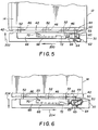
- Figs. 5 and 6 are diagrammatic plan views of a storage phosphor extraction mechanism.
- Figs. 7 and 8 are respective exploded and plan views of another storage phosphor extraction mechanism.
-
- Referring to Figs. 1-2, there is illustrated a
storage phosphor reader 10 including components for scanning a storage phosphor. In the particular embodiment illustrated, thereader 10 is designed to receive acassette 12 having astorage phosphor 14 disposed therein.Storage phosphor 14 is capable of storing a latent image upon x-radiation of a body part. A digital image can be extracted for later viewing or development of a x-ray film by reading the latent x-ray image with a laser scanning reader. The reader is of the raster scanner-type. Briefly, when the image on thestorage phosphor 14 is exposed to a stimulating ray beam, such as a laser beam, thestorage phosphor 14 emits a light in proportion to a stored x-radiation energy. The light thus emitted is photoelectrically detected and converted to an electrical signal, and the radiation image of the object is reproduced visually by exposure of the image signal on a recording medium such as a photographic film or on a video monitor. - The stimulating of the storage phosphor by a laser beam is typically done using a raster scanning technique. The
mechanism 10 includes amovable stage 16 which includes adrive screw 18 which is mounted tobase 20 of the reader. Thedrive screw 18 is in threaded engagement withmovable stage 16 so as to move thestage 16 from the receiving position illustrated in Fig. 1 to the scannedposition 22 illustrated by dash lines also in Fig. 1. Anappropriate stepper motor 23 andcorresponding transmission 25 is provided for rotating thedrive screw 18 such that thestage 16 can move in the X direction. Thestage 16 is supported by a pair ofguide rails 24,26 which are axially spaced apart and secured to thebase 20.Guide rails 24,26 anddrive screw 18 are in substantial parallel alignment with each other. - The reader includes a cassette clamping mechanism at
cassette receiving station 25. The clamping mechanism includes anupper clamp jaw 27 andlower clamp jaw 28 which are used to clamp the cassette in a predetermined fixed position. - The
mechanism 10 includes anextractor bar assembly 30 which is mounted tostage 16 for movement in the Y direction byextractor drive 100. The X and Y directions, as set forth in this application, have been provided merely for the sake of clarity in describing the direction of movement of various parts, it being understood that any coordinate system may be substituted as desired. In the particular embodiment, theextractor bar assembly 30 is designed for movement to and away from thecassette 12, while thestage 16 moves in a direction substantially transverse to the end/side of the cassette facing theextractor bar assembly 30. Thecassette 12 is of the type designed for removing the storage phosphor from the end/side of the cassette. Briefly, as shown in Fig. 2, thecassette 12 comprises a shell having upper andlower panels side caps storage phosphor 14 is disposed therein and is secured to aremovable end cap 42. Theend cap 42 includes a latching mechanism for releasing theend cap 42 from thecassette 12. Additionally, theend cap 42 includes an alignment opening 44, disposed preferably along one side of thecassette 12. Theend cap 42 further includes a plurality ofaccess openings 46 designed to receive hook members designed to engage the latching mechanism disposed within the cassette (not shown). The latching mechanism is of a construction such that when the hook mechanism is moved in a particular direction, it will release theend cap 42 from thecassette 12 allowing theend cap 42 and attachedstorage phosphor 14 to be removed therefrom. - Fig. 3 shows a different sized cassette 12' having a shell with upper and lower panels 32',34', respectively, and three side caps 36',38',40'. Removable storage phosphor 14' is disposed therein and is secured to an end cap 42'. End cap 42' has alignment opening 44' and access openings 46'. Cassette 12' is preferably held in a pallet such as disclosed in U.S. Patent 5,277,322 to facilitate handling of the cassette.
-
Cassette 12 contains alarger storage phosphor 14 than the storage phosphor 14' of cassette 12'. For example,storage phosphor 14 has the dimensions 35 cm × 43 cm and storage phosphor 14' has thedimensions 20 cm × 25 cm. - Referring now to Figs. 5 and 6, there is shown in greater detail
extractor bar assembly 30. As shown,extractor bar assembly 30 includes alocator pin 50 andhook members 52.Pin 50 is adapted to enteralignment opening 44 instorage phosphor 14 andhook members 52 are adapted to enteraccess openings 46 instorage phosphor 14.Pin 50 is fixedly mounted onslider 60. An overcenter spring 62 is connected byfastener 64 toassembly 30 and byfastener 65 toslider 60. Hookmembers 52 are mounted onhook plate 66. Awedge mechanism 68 includes apin 69 which is engageable byslider 60. -
Extractor bar assembly 30 mounted onstage 16 is driven in the direction ofarrow 202 by extractor drive 100 (Fig. 1) onstage 16 and in the direction ofarrow 200 bystage 16,motor 23 andtransmission 25 to insertlocator pin 50 intoalignment opening 44 andhook members 52 intoaccess openings 46. The direction ofstage 16 is reversed to moveassembly 30 in the direction of arrow 204 (Fig. 6).Slider 60 engagespin 69 which urgeswedge mechanism 68 forward into contact withend cap 42 ofstorage phosphor 14 by means of camming surfaces 70,72. Overcenter spring 62 locks hookmembers 52 in engagement withstorage phosphor 14.Extraction bar assembly 30 is then moved bydrive 100 in the direction ofarrow 206 to completely removestorage phosphor 14 fromcassette 12. - This process is reversed to insert
storage phosphor 14 back intocassette 12. -
Wedge mechanism 68 holdsend cap 42 rigid relative tostorage phosphor 14 so that wear ofpin 44, hooks 52, andend cap 42 is minimized during extraction and insertion ofstorage phosphor 14. - Referring now to Figs. 7 and 8, there is shown another extractor bar assembly 30'. As shown, extractor bar assembly 30' includes a locator pin 50' and hook members 52'. Pin 50' is mounted on slider 60'. Over center spring 62' is connected by fastener 64' to assembly 30' and by fastener 65' to slider 60'. Hook members 52' are mounted on hook plate 66'. Hook plate 66' is mounted on assembly 30' by
fasteners respective washers Springs spring 60. - The extractor bar assembly 30' of Figs. 7 and 8 differs from the
extractor bar assembly 30 of Figs. 5 and 6 in the mounting and operation of therespective wedge mechanism 68,68'.Wedge mechanism 68 is normally retracted and is extended only afterlocator pin 50 has enteredalignment opening 44 instorage phosphor 14. Whenassembly 30 is moved to engagehook members 52 withend cap 42,slider 60 throughpin 69,cams wedge mechanism 68 forward into contact withend cap 42. On the other hand, wedge mechanism 68' is normally urged forward to an extended position so that as pin 50' is moved intoalignment opening 44, wedge mechanism 68' contacts endcap 42 and stays in contact withend cap 42 during the locking movement ofhook members 52. - The distance D between alignment opening 44 in
end cap 42 ofstorage phosphor 14 andreference corner 45 is greater than the distance D' between alignment opening 44' in end cap 42' of storage phosphor 14' and reference corner 45' (See: Figs. 2 and 3). Thus, some technique must be used to alignpin 50 ofassembly 30 with opening 44 ofstorage phosphor 14 to avoid the disadvantages of the alignment mechanism of U.S. Patent 5,330,309. - As shown in Fig. 4,
end cap 42 ofstorage phosphor 14 is provided with abar code label 300.Label 300 includes abar code 302 encoding various data including storage phosphor ID number, storage phosphor dimensional size (e.g., 35 cm × 43 cm), and speed (of screen). Mounted onupper clamp jaw 27 is abar code reader 308 of a known type. Beforecassette 12 is clamped betweenclamp jaws cassette receiving station 25,bar code reader 308 reads thebar code 302 including storage phosphor dimensional size data. This data is transmitted to control 102 (such as a microprocessor system).Control 102 uses the storage phosphor dimensional data to controlextractor drive 100 and stage drivemotor 23 to positionextraction bar assembly 30 so thatpin 50 is exactly aligned withalignment opening 44 inend cap 42. This bar code alignment system eliminates the pin switch system of U.S. Patent 5,330,309, thus increasing reliability, minimizing reader down time, and eliminating damage to the cassette caused by the locating pin striking the cassette. - Although the
bar code reader 308 has been shown mounted onupper clamp jaw 27, it could also be located inlower jaw member 28, on extractingbar assembly 30, or any other propitious location. - The invention has been described in detail with particular reference to certain preferred embodiments thereof, but it will be understood that variations and modifications can be effected within the spirit and scope of the invention.
-
- 10
- reader
- 12,12'
- cassettes
- 14,14'
- storage phosphors
- 16
- movable stage
- 18
- drive screw
- 19
- drive nut
- 20
- base
- 21
- element
- 22
- scanned position
- 23
- stepper motor
- 24, 26
- guide rails
- 25
- cassette receiving station
- 27
- clamp jaw
- 30,30'
- extractor bar assembly
- 32,32'
- upper panels
- 34,34'
- lower panels
- 36,36',38,38',40,40'
- side caps
- 42,42'
- removable end caps
- 44,44'
- alignment openings
- 45,45'
- reference corners
- 46,46'
- access openings
- 50,50'
- locator pins
- 52,52'
- hook members
- 60,60'
- sliders
- 62,62'
- over center springs
- 64,64',65,65'
- fasteners
- 66,66'
- hook plates
- 68,68'
- wedge mechanisms
- 69
- pin
- 70,72
- camming surfaces
- 80,82
- fasteners
- 84,86,88,90
- washers
- 92,94
- springs
- 100
- extractor drive
- 102
- control
- 300
- bar code label
- 302
- bar code
- 308
- bar code reader
Claims (5)
- A storage phosphor reader comprising;a receiving station for receiving a cassette containing a removable storage phosphor;a movable extraction mechanism for extracting and replacing a storage phosphor contained in a received cassette;a bar code located on said cassette/storage phosphor, said bar code including dimension data of a storage phosphor contained in said cassette;a bar code reader located at said receiving station for reading said bar code dimension data on a received storage phosphor cassette; andcontrol means for controlling the movement of said extraction mechanism relative to a received storage phosphor cassette as a function of said read dimension data.
- The storage phosphor reader of claim 1 wherein said receiving station includes cassette clamping means for clamping a cassette at said receiving station and wherein said bar code reader is mounted in association with said clamping means to read said bar code located on said received cassette/storage phosphor.
- The storage phosphor reader of claim 1 wherein said received cassette has an open end closed by an end cap of said storage phosphor and wherein said bar code is located on said end cap facing said extraction mechanism.
- The storage phosphor reader of claim 3 wherein said receiving station has a clamp for clamping said cassette to said storage phosphor reader and wherein said bar code reader is mounted on said clamp in facing relationship to said bar code.
- The storage phosphor reader of claim 3 wherein said end cap has a face with an alignment opening and wherein said extraction mechanism includes a locating pin facing said end cap, and wherein said control means controls the movement of said extraction mechanism so that said locating pin is inserted into said alignment opening without engagement of said pin with said end cap face.
Applications Claiming Priority (2)
| Application Number | Priority Date | Filing Date | Title |
|---|---|---|---|
| US08/936,069 US6032856A (en) | 1997-09-23 | 1997-09-23 | Storage phosphor reader using bar code for cassette extraction and alignment |
| US936069 | 1997-09-23 |
Publications (2)
| Publication Number | Publication Date |
|---|---|
| EP0903618A2 true EP0903618A2 (en) | 1999-03-24 |
| EP0903618A3 EP0903618A3 (en) | 1999-08-11 |
Family
ID=25468133
Family Applications (1)
| Application Number | Title | Priority Date | Filing Date |
|---|---|---|---|
| EP98203046A Withdrawn EP0903618A3 (en) | 1997-09-23 | 1998-09-11 | Storage phosphor reader using bar code for cassette extraction and alignment |
Country Status (3)
| Country | Link |
|---|---|
| US (1) | US6032856A (en) |
| EP (1) | EP0903618A3 (en) |
| JP (1) | JPH11167174A (en) |
Families Citing this family (4)
| Publication number | Priority date | Publication date | Assignee | Title |
|---|---|---|---|---|
| US6191426B1 (en) * | 1997-11-10 | 2001-02-20 | Konica Corporation | Cassette |
| EP1039338A3 (en) * | 1999-03-24 | 2003-07-16 | Fuji Photo Film Co., Ltd. | Cassette for stimulable phosphor sheet, identification means therefor, and image information reading apparatus |
| US6244507B1 (en) * | 1999-06-25 | 2001-06-12 | Canon Kabushiki Kaisha | Automatic grid parameter logging for digital radiography |
| US7623621B1 (en) | 2008-03-13 | 2009-11-24 | The United States Of America As Represented By The Administrator Of The National Aeronautics And Space Administration | Method and system for identifying and authenticating an object |
Citations (4)
| Publication number | Priority date | Publication date | Assignee | Title |
|---|---|---|---|---|
| WO1992014403A1 (en) * | 1991-02-15 | 1992-09-03 | Eastman Kodak Company | Computerized radiography and patient identification system |
| US5277322A (en) * | 1992-11-25 | 1994-01-11 | Eastman Kodak Company | Pallet for holding a cassette |
| EP0601355A1 (en) * | 1992-11-25 | 1994-06-15 | Eastman Kodak Company | Reader having cassette locating and unlatching mechanism |
| US5376806A (en) * | 1993-06-30 | 1994-12-27 | Eastman Kodak Company | Storage phosphor reader having storage phosphor size and exposure speed detection |
-
1997
- 1997-09-23 US US08/936,069 patent/US6032856A/en not_active Expired - Fee Related
-
1998
- 1998-09-11 EP EP98203046A patent/EP0903618A3/en not_active Withdrawn
- 1998-09-22 JP JP10268071A patent/JPH11167174A/en active Pending
Patent Citations (5)
| Publication number | Priority date | Publication date | Assignee | Title |
|---|---|---|---|---|
| WO1992014403A1 (en) * | 1991-02-15 | 1992-09-03 | Eastman Kodak Company | Computerized radiography and patient identification system |
| US5334851A (en) * | 1991-02-15 | 1994-08-02 | Eastman Kodak Company | Computed radiography patient identification system |
| US5277322A (en) * | 1992-11-25 | 1994-01-11 | Eastman Kodak Company | Pallet for holding a cassette |
| EP0601355A1 (en) * | 1992-11-25 | 1994-06-15 | Eastman Kodak Company | Reader having cassette locating and unlatching mechanism |
| US5376806A (en) * | 1993-06-30 | 1994-12-27 | Eastman Kodak Company | Storage phosphor reader having storage phosphor size and exposure speed detection |
Also Published As
| Publication number | Publication date |
|---|---|
| JPH11167174A (en) | 1999-06-22 |
| US6032856A (en) | 2000-03-07 |
| EP0903618A3 (en) | 1999-08-11 |
Similar Documents
| Publication | Publication Date | Title |
|---|---|---|
| US5461492A (en) | Film scanner with in-line dual scanning gates | |
| KR100523306B1 (en) | Radiation image reading device | |
| US5330309A (en) | Reader having cassette locating and unlatching mechanism | |
| US6032856A (en) | Storage phosphor reader using bar code for cassette extraction and alignment | |
| US5954469A (en) | Extraction bar mechanism for storage phosphor reader | |
| EP0599128A2 (en) | Storage phosphor reader diagnostics | |
| EP1102118B1 (en) | Computed radiography reader with vertical scanning | |
| US5990487A (en) | Stage plunger mechanism for storage phosphor reader | |
| WO2006065488A1 (en) | Multicassette autoloader for a storage phosphor reader | |
| US5555042A (en) | Apparatus for automatically feeding slides into a film scanner | |
| US7030404B2 (en) | Methods and apparatus for handling image recording media | |
| US4984260A (en) | Radiation diagnostic device | |
| US6276827B1 (en) | Cassette tray for radiography | |
| US3997256A (en) | Microfiche cartridge | |
| JP2727272B2 (en) | Cassette | |
| US7482613B2 (en) | Multicassette autoloader for a storage phosphor reader | |
| EP1104892B1 (en) | CR reader with integrated control mechanism | |
| US20060131526A1 (en) | U-flow multicassette autoloader for a storage phosphor reader | |
| US4531829A (en) | Multi-form slide selection apparatus | |
| US7855816B2 (en) | Movable part locking jig and image forming apparatus incorporating such movable part locking jig | |
| US4928016A (en) | Magazine for accommodating recording medium for electron microscope | |
| GB2210731A (en) | Cartridge receiving apparatus | |
| EP0513342B1 (en) | Apparatus for orienting storage phosphor cassette | |
| US4652943A (en) | Head loading device for electronic still single-lens reflex camera | |
| EP1502152B1 (en) | X-ray cassette with radiation conversion window (mev-kev) and automatic loader |
Legal Events
| Date | Code | Title | Description |
|---|---|---|---|
| PUAI | Public reference made under article 153(3) epc to a published international application that has entered the european phase |
Free format text: ORIGINAL CODE: 0009012 |
|
| AK | Designated contracting states |
Kind code of ref document: A2 Designated state(s): DE FR GB |
|
| AX | Request for extension of the european patent |
Free format text: AL;LT;LV;MK;RO;SI |
|
| PUAL | Search report despatched |
Free format text: ORIGINAL CODE: 0009013 |
|
| AK | Designated contracting states |
Kind code of ref document: A3 Designated state(s): AT BE CH CY DE DK ES FI FR GB GR IE IT LI LU MC NL PT SE |
|
| AX | Request for extension of the european patent |
Free format text: AL;LT;LV;MK;RO;SI |
|
| RIC1 | Information provided on ipc code assigned before grant |
Free format text: 6G 03B 42/02 A, 6G 03B 42/04 B, 6G 01T 1/29 B |
|
| 17P | Request for examination filed |
Effective date: 20000112 |
|
| AKX | Designation fees paid |
Free format text: DE FR GB |
|
| 17Q | First examination report despatched |
Effective date: 20031222 |
|
| STAA | Information on the status of an ep patent application or granted ep patent |
Free format text: STATUS: THE APPLICATION IS DEEMED TO BE WITHDRAWN |
|
| 18D | Application deemed to be withdrawn |
Effective date: 20040402 |