EP0904573B1 - A method for surveying the condition of a control valve, and a valve apparatus - Google Patents
A method for surveying the condition of a control valve, and a valve apparatus Download PDFInfo
- Publication number
- EP0904573B1 EP0904573B1 EP97926021A EP97926021A EP0904573B1 EP 0904573 B1 EP0904573 B1 EP 0904573B1 EP 97926021 A EP97926021 A EP 97926021A EP 97926021 A EP97926021 A EP 97926021A EP 0904573 B1 EP0904573 B1 EP 0904573B1
- Authority
- EP
- European Patent Office
- Prior art keywords
- valve
- certain
- actuator
- fault
- time
- Prior art date
- Legal status (The legal status is an assumption and is not a legal conclusion. Google has not performed a legal analysis and makes no representation as to the accuracy of the status listed.)
- Expired - Lifetime
Links
- 238000000034 method Methods 0.000 title claims description 18
- 230000008859 change Effects 0.000 claims description 34
- 230000015654 memory Effects 0.000 claims description 4
- 230000008569 process Effects 0.000 description 10
- 238000012360 testing method Methods 0.000 description 10
- 238000012544 monitoring process Methods 0.000 description 6
- 230000003247 decreasing effect Effects 0.000 description 4
- 230000006870 function Effects 0.000 description 4
- 230000001276 controlling effect Effects 0.000 description 3
- 238000012423 maintenance Methods 0.000 description 3
- 238000004519 manufacturing process Methods 0.000 description 3
- 238000010586 diagram Methods 0.000 description 2
- 238000005259 measurement Methods 0.000 description 2
- 230000007246 mechanism Effects 0.000 description 2
- 238000012545 processing Methods 0.000 description 2
- 230000008901 benefit Effects 0.000 description 1
- 230000003449 preventive effect Effects 0.000 description 1
- 230000001105 regulatory effect Effects 0.000 description 1
- 230000004044 response Effects 0.000 description 1
- 238000012546 transfer Methods 0.000 description 1
Images


Classifications
-
- F—MECHANICAL ENGINEERING; LIGHTING; HEATING; WEAPONS; BLASTING
- F16—ENGINEERING ELEMENTS AND UNITS; GENERAL MEASURES FOR PRODUCING AND MAINTAINING EFFECTIVE FUNCTIONING OF MACHINES OR INSTALLATIONS; THERMAL INSULATION IN GENERAL
- F16K—VALVES; TAPS; COCKS; ACTUATING-FLOATS; DEVICES FOR VENTING OR AERATING
- F16K37/00—Special means in or on valves or other cut-off apparatus for indicating or recording operation thereof, or for enabling an alarm to be given
- F16K37/0075—For recording or indicating the functioning of a valve in combination with test equipment
- F16K37/0083—For recording or indicating the functioning of a valve in combination with test equipment by measuring valve parameters
-
- F—MECHANICAL ENGINEERING; LIGHTING; HEATING; WEAPONS; BLASTING
- F15—FLUID-PRESSURE ACTUATORS; HYDRAULICS OR PNEUMATICS IN GENERAL
- F15B—SYSTEMS ACTING BY MEANS OF FLUIDS IN GENERAL; FLUID-PRESSURE ACTUATORS, e.g. SERVOMOTORS; DETAILS OF FLUID-PRESSURE SYSTEMS, NOT OTHERWISE PROVIDED FOR
- F15B19/00—Testing; Calibrating; Fault detection or monitoring; Simulation or modelling of fluid-pressure systems or apparatus not otherwise provided for
- F15B19/005—Fault detection or monitoring
-
- F—MECHANICAL ENGINEERING; LIGHTING; HEATING; WEAPONS; BLASTING
- F16—ENGINEERING ELEMENTS AND UNITS; GENERAL MEASURES FOR PRODUCING AND MAINTAINING EFFECTIVE FUNCTIONING OF MACHINES OR INSTALLATIONS; THERMAL INSULATION IN GENERAL
- F16K—VALVES; TAPS; COCKS; ACTUATING-FLOATS; DEVICES FOR VENTING OR AERATING
- F16K31/00—Actuating devices; Operating means; Releasing devices
- F16K31/12—Actuating devices; Operating means; Releasing devices actuated by fluid
- F16K31/16—Actuating devices; Operating means; Releasing devices actuated by fluid with a mechanism, other than pulling-or pushing-rod, between fluid motor and closure member
- F16K31/163—Actuating devices; Operating means; Releasing devices actuated by fluid with a mechanism, other than pulling-or pushing-rod, between fluid motor and closure member the fluid acting on a piston
- F16K31/1635—Actuating devices; Operating means; Releasing devices actuated by fluid with a mechanism, other than pulling-or pushing-rod, between fluid motor and closure member the fluid acting on a piston for rotating valves
-
- F—MECHANICAL ENGINEERING; LIGHTING; HEATING; WEAPONS; BLASTING
- F16—ENGINEERING ELEMENTS AND UNITS; GENERAL MEASURES FOR PRODUCING AND MAINTAINING EFFECTIVE FUNCTIONING OF MACHINES OR INSTALLATIONS; THERMAL INSULATION IN GENERAL
- F16K—VALVES; TAPS; COCKS; ACTUATING-FLOATS; DEVICES FOR VENTING OR AERATING
- F16K37/00—Special means in or on valves or other cut-off apparatus for indicating or recording operation thereof, or for enabling an alarm to be given
- F16K37/0075—For recording or indicating the functioning of a valve in combination with test equipment
- F16K37/0091—For recording or indicating the functioning of a valve in combination with test equipment by measuring fluid parameters
-
- F—MECHANICAL ENGINEERING; LIGHTING; HEATING; WEAPONS; BLASTING
- F15—FLUID-PRESSURE ACTUATORS; HYDRAULICS OR PNEUMATICS IN GENERAL
- F15B—SYSTEMS ACTING BY MEANS OF FLUIDS IN GENERAL; FLUID-PRESSURE ACTUATORS, e.g. SERVOMOTORS; DETAILS OF FLUID-PRESSURE SYSTEMS, NOT OTHERWISE PROVIDED FOR
- F15B2211/00—Circuits for servomotor systems
- F15B2211/60—Circuit components or control therefor
- F15B2211/63—Electronic controllers
- F15B2211/6303—Electronic controllers using input signals
- F15B2211/6306—Electronic controllers using input signals representing a pressure
- F15B2211/6309—Electronic controllers using input signals representing a pressure the pressure being a pressure source supply pressure
-
- F—MECHANICAL ENGINEERING; LIGHTING; HEATING; WEAPONS; BLASTING
- F15—FLUID-PRESSURE ACTUATORS; HYDRAULICS OR PNEUMATICS IN GENERAL
- F15B—SYSTEMS ACTING BY MEANS OF FLUIDS IN GENERAL; FLUID-PRESSURE ACTUATORS, e.g. SERVOMOTORS; DETAILS OF FLUID-PRESSURE SYSTEMS, NOT OTHERWISE PROVIDED FOR
- F15B2211/00—Circuits for servomotor systems
- F15B2211/60—Circuit components or control therefor
- F15B2211/63—Electronic controllers
- F15B2211/6303—Electronic controllers using input signals
- F15B2211/6306—Electronic controllers using input signals representing a pressure
- F15B2211/6313—Electronic controllers using input signals representing a pressure the pressure being a load pressure
-
- F—MECHANICAL ENGINEERING; LIGHTING; HEATING; WEAPONS; BLASTING
- F15—FLUID-PRESSURE ACTUATORS; HYDRAULICS OR PNEUMATICS IN GENERAL
- F15B—SYSTEMS ACTING BY MEANS OF FLUIDS IN GENERAL; FLUID-PRESSURE ACTUATORS, e.g. SERVOMOTORS; DETAILS OF FLUID-PRESSURE SYSTEMS, NOT OTHERWISE PROVIDED FOR
- F15B2211/00—Circuits for servomotor systems
- F15B2211/60—Circuit components or control therefor
- F15B2211/63—Electronic controllers
- F15B2211/6303—Electronic controllers using input signals
- F15B2211/6336—Electronic controllers using input signals representing a state of the output member, e.g. position, speed or acceleration
-
- F—MECHANICAL ENGINEERING; LIGHTING; HEATING; WEAPONS; BLASTING
- F15—FLUID-PRESSURE ACTUATORS; HYDRAULICS OR PNEUMATICS IN GENERAL
- F15B—SYSTEMS ACTING BY MEANS OF FLUIDS IN GENERAL; FLUID-PRESSURE ACTUATORS, e.g. SERVOMOTORS; DETAILS OF FLUID-PRESSURE SYSTEMS, NOT OTHERWISE PROVIDED FOR
- F15B2211/00—Circuits for servomotor systems
- F15B2211/70—Output members, e.g. hydraulic motors or cylinders or control therefor
- F15B2211/705—Output members, e.g. hydraulic motors or cylinders or control therefor characterised by the type of output members or actuators
- F15B2211/7051—Linear output members
- F15B2211/7053—Double-acting output members
-
- F—MECHANICAL ENGINEERING; LIGHTING; HEATING; WEAPONS; BLASTING
- F15—FLUID-PRESSURE ACTUATORS; HYDRAULICS OR PNEUMATICS IN GENERAL
- F15B—SYSTEMS ACTING BY MEANS OF FLUIDS IN GENERAL; FLUID-PRESSURE ACTUATORS, e.g. SERVOMOTORS; DETAILS OF FLUID-PRESSURE SYSTEMS, NOT OTHERWISE PROVIDED FOR
- F15B2211/00—Circuits for servomotor systems
- F15B2211/80—Other types of control related to particular problems or conditions
- F15B2211/857—Monitoring of fluid pressure systems
-
- G—PHYSICS
- G01—MEASURING; TESTING
- G01R—MEASURING ELECTRIC VARIABLES; MEASURING MAGNETIC VARIABLES
- G01R31/00—Arrangements for testing electric properties; Arrangements for locating electric faults; Arrangements for electrical testing characterised by what is being tested not provided for elsewhere
- G01R31/50—Testing of electric apparatus, lines, cables or components for short-circuits, continuity, leakage current or incorrect line connections
- G01R31/72—Testing of electric windings
-
- Y—GENERAL TAGGING OF NEW TECHNOLOGICAL DEVELOPMENTS; GENERAL TAGGING OF CROSS-SECTIONAL TECHNOLOGIES SPANNING OVER SEVERAL SECTIONS OF THE IPC; TECHNICAL SUBJECTS COVERED BY FORMER USPC CROSS-REFERENCE ART COLLECTIONS [XRACs] AND DIGESTS
- Y10—TECHNICAL SUBJECTS COVERED BY FORMER USPC
- Y10T—TECHNICAL SUBJECTS COVERED BY FORMER US CLASSIFICATION
- Y10T137/00—Fluid handling
- Y10T137/8158—With indicator, register, recorder, alarm or inspection means
- Y10T137/8175—Plural
-
- Y—GENERAL TAGGING OF NEW TECHNOLOGICAL DEVELOPMENTS; GENERAL TAGGING OF CROSS-SECTIONAL TECHNOLOGIES SPANNING OVER SEVERAL SECTIONS OF THE IPC; TECHNICAL SUBJECTS COVERED BY FORMER USPC CROSS-REFERENCE ART COLLECTIONS [XRACs] AND DIGESTS
- Y10—TECHNICAL SUBJECTS COVERED BY FORMER USPC
- Y10T—TECHNICAL SUBJECTS COVERED BY FORMER US CLASSIFICATION
- Y10T137/00—Fluid handling
- Y10T137/8158—With indicator, register, recorder, alarm or inspection means
- Y10T137/8225—Position or extent of motion indicator
- Y10T137/8242—Electrical
Definitions
- the present invention concerns a method for surveying the condition of a control valve apparatus, the position of which is adjusted by means of an actuator controlled by an electropneumatic positioner and operated by means of pressure medium, whereby the operation of the valve is monitored by sensors that during the valve operation read at certain reading intervals the readings at least from the control signal of the valve, the input pressure of the positioner, the difference between the input and output pressure of the actuator, and the position of the valve, and the fault causing the deviating reading is located by means of a microprocessor by using the readings given by the sensors and deduction rules stored in the microprocessor.
- EP-A-0 708 389 discloses such a method according to the preamble of claim 1.
- the invention also concerns a control valve apparatus comprising a valve, an actuator driven by means of a cylinder-piston device, and an electropneumatic positioner, sensors for monitoring at least the control signal of the valve, the input pressure of the positioner, the difference between the input and output pressure of the actuator, and the valve position as well as means for storing the information received from the sensors and the deduction rules to be used for locating a fault and for processing the information received from the sensors in accordance with these rules.
- a control valve and its operation are known in the art and there is no need to describe it in more detail in this connection.
- the valve can be a quarter-rotational or a linear valve, said designations describing the moving direction of the closing element of the valve in the controlling situation.
- a quarter-rotational valve can be e.g. a ball valve or a butterfly valve. Examples of a ball valve have been described e.g. in US patent publication No. 4,747,578.
- the valve is operated by means of an actuator that turns the turning shaft of the closing element between the closed and the opened position.
- the actuator can be driven by means of a cylinder piston device controlled by a pilot valve. This pilot valve is located in the positioner of the control valve.
- the positioner is a device for amplifying the control signal into the operation pressure of the pneumatic actuator.
- the electric signal is amplified into the pneumatic operation pressure.
- the positioner by means of a feed-back element, also positions the valve to correspond to the control signal.
- the diagnostics of control valves equipped with a pneumatic actuator is in general based on tests performed on the control valves, such as step-function response and hysteresis tests. A requirement for performing the tests is that the process is stopped, whereby the tests are performed at site of the valves.
- the testing equipment often also includes complicated sensors that can make the testing on the field complicated (US patent publication Nr. 5,197,328). This is so called off-line diagnostics.
- the diagnostics can also be performed on-line, whereby the positioner of the control valve monitors e.g. the position message of the valve and gives an alert if the position message deviates too much from the value presupposed by the control system.
- Part of the on-line diagnostics are also the operation counters of the valve that give an alert when the number of the operations exceeds a certain predetermined limit. This diagnostics system, however, does not include any deduction procedure by which the faults could be located.
- valves In both of the US patent publications No. 5,329,465 and No. 4,694,390, valves have been described, in the control system of which separate measuring sensors are used.
- the inventions described in the publications concern an on-off regulation of the valve, not continuous controlling.
- sensors are used for condition surveying of the valve and for collecting historical data for the data base.
- the fault analysis is made by comparing the measured values with the values collected earlier for the data base.
- the position of the valve is not adjusted continuously but the valve is moving only when it is closed or opened. This can happen a couple of times per day or the adjustment interval can even be several months.
- the values required for the fault analysis are monitored only during this opening and closing movement that happens at long intervals.
- a method in accordance with the present invention is characterized in that
- An apparatus in accordance with the present invention is characterized in that the deduction rules have been programmed in the microprocessor of a digital positioner, said microprocessor processing the readings of the sensors.
- the invention is directed to an electrically controlled pneumatic system, where the sensors used for controlling operation are also used for fault analysis. Thus, the values are collected from the valve by means of the sensors continuously.
- the positioning unit includes an integral self-diagnostic part that in a bus-constructed control makes it possible to transmit the information immediately to the control unit or the monitoring room.
- the invention is based on a logic programmed in the digital positioner, based on which the processor of the positioner performs an on-line condition monitoring of the control valve.
- the quantities to be monitored by the positioner are the control current signal, the difference between the input and output pressure of the actuator, the valve position and the input pressure of the positioner.
- the diagnostics tend to locate the faulted object in the control valve.
- the circuit card of the digital positioner has its own integral diagnostics, by means of which the positioner informs about the faults on the circuit cards. This diagnostics of the circuit card is, however, not a part of the present invention.
- the logical rules are formed of rules, that all must be fulfilled in order to activate the diagnostics to give a fault message. As a result, the diagnostics inform the eventual faulted object.
- the invention concerns the logic of the diagnostics to be programmed into the digital positioner of a control valve.
- the logic is formed of a deduction mechanism formed by Boolean rules.
- the positioner monitors during the process i.a. the position information of the control valve, the difference between the input and output: pressure of the actuator, the control signal and the level of the input pressure of the positioner. These values and their changes are compared with the deduction rules formed by Boolean rules, based on which the condition of the control valve is noted and, if necessary, alerts are given, by which the eventually faulted components are located (positioner, actuator, valve).
- the deduction rules are divided into five parts giving different alerts, in other words, giving the fault message.
- Alert 1 is given, when a fault has been found on the circuit card of the positioner (current message, angle sensor, preregulating valves, pressure sensors, EEPROM and ROM memories). This diagnostics are taken care of by separate diagnostics made on the circuit card, the closer contents of which are not an object of the present invention.
- Alert 2 is given, when the control signal of the valve changes, but the difference between the input and output pressure of the actuator, and the position of the valve are not changed. In that case the fault message tells that there is a fault in the operation of the slide of the positioner.
- Alert 3 is given, when the difference quantity between the valve position corresponding to the control signal and the measured valve position exceeds the set limit continuously for a certain time.
- the fault message tells in that case the most probable objects of the fault. In case it is a friction problem, also alert 4 and/or alert 5 can be given.
- Alert 4 is given, when the control signal changes and the difference between the input and output pressure of the actuator increases, but the position of the valve is not changed. In that case, it is a question of a friction problem.
- Alert 5 is given, when the trend of the load factor exceeds a set limit. In that case, it is a question of a friction problem.
- Information on the alerts can be transmitted automatically e.g. through an HART data transfer channel e.g. to a monitoring room.
- HART data transfer channel e.g. to a monitoring room.
- a valve can operate even a long time indefinitely disturbing the operation of the process before it is serviced. In the worst case the valve can crack up causing expensive production shutdowns. These cases can be avoided, if information on the condition of the valve can be received continuously during the process.
- valves at the most critical points are serviced without knowing their condition in advance.
- valves can be serviced that would not have needed any service yet, or service of valves that would have needed to be serviced can be neglected, because there is not enough time to service all the valves during the outage. If on-line information is received on the condition of the valves, the valves that need service can be located, and by means of tests a closer diagnostic can be made in order to determine more precisely their factual need of service.
- the final advantage to be gained through the on-line diagnostics is the increasing safety of the process and decreasing of the costs while the feasibility of the process will be increased and the production losses decreased. Energy is saved, wastages are decreased and unpredictable production outages are avoided. Also the size of the spare part stocks can be decreased.
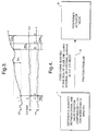
- Figure 1 illustrates an apparatus comprising a control valve 101, an actuator 103 driven by a cylinder-piston device 102 and a positioner 104.
- the actuator is controlled by a pilot valve 105.
- Messages of the positioner are processed by a printed circuit card 106 where the control information is stored in.
- a sensor 107 measures the position s of a closing member 108, a sensor 109 measures the input pressure p s of the positioner and a sensor 110 measures the difference ⁇ p between the input and output pressure of the actuator. These sensors are located in the positioner. The flow of the different electric messages and measurements is marked on the diagram. Control signal i is input in the system.
- Alert 1 indicates a circuit card problem of the positioner, as stated above, but it is not a part of the present invention.
- Alert 2 indicates a slide problem of the control valve.
- Figure 2 illustrates as a diagram four different conditions by means of which the deduction concerning the alert 2 is performed.
- the operation for the alert 2 is described, that is, the quantities monitored as a function of time and their parameters.
- Point A is the point of the time axis, where the values of the control signal i , the difference ⁇ p between the input and output pressure of the actuator, and the valve position s to be monitored have for repeating reading cycles been within the given limit values for a required time.
- the values of the quantities of this balance state A named as "the initial situation” are stored in the registers. If a change of > 5 % occurs in the control signal, the time counter starts.
- the time counter is reset to zero and there will be no changes in the other registers if during the change of the control signal i no change of > 1 % has occurred in the valve positions in relation to the value of the initial situation A. In that case, a new initial situation A has to be set. If both the control signal i and the valve position s exceed the values of the balance conditions of the initial situation A, a new initial situation will be searched.
- Condition 1 A change of more than 5 % of the control signal i lasts more than 120 s, in other words, from point B to point D in figure 3.
- Condition 2 A change of the difference ⁇ p between the input and output pressure of the actuator is within the predetermined limits, in figure 3 the change is ⁇ 0,2 bar in the period of time A ⁇ B and from B to C.
- Condition 3 A change of the valve position s is within the predetermined limits, in figure 3 the change ⁇ 1 % in the period of time A ⁇ B and from B to C.
- the range to be considered is from 10 to 90 % of the movement range of the control valve, in other words, the most extreme starting and ending positions of the movement range are not considered.
- a change of ⁇ 2 % of the control signal i and duration of 10 s; a change ⁇ 0,2 bar of the difference ⁇ p of the input and output pressure of the actuator, and duration of 10 s; and a change of ⁇ 1 % of the position s of the control valve and duration of 10 s have been selected as parameters describing a balance state.
- the corresponding parameters of the alert state are: a change of > 5 % of the control signal i and time of 120 s, in other words on the time axis from B to D; a change of ⁇ 0,2 % of the difference ⁇ p of the input and output pressure, and time of 30 s, in other words on the time axis from B to C; and a change of ⁇ 1 % of the position s and time of 120 s, i.e. from B to D.
- Naturally also other parameter values can be selected according to need. From the alerts, the first and the last one will be stored as well as their times of occurence and the total number of the alerts. The reading cycle is 0,1 s.
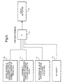
- Alert 3 means a big quantity of difference between the control signal and the valve position.
- Figure 4 illustrates the condition of the alert 3 and the conclusion.
- Condition 7 The quantity of difference between the valve position corresponding to the signal and the measured valve position is > 5 % continuously for more than 10 minutes.
- the location 9 of the fault is in the positioner, actuator or valve.
- the range to be considered is from 10 to 90 % of the movement range of the valve.
- Parameters are selected to be the same as the above mentioned values of the condition 7, that is, the quantity of difference of > 5 % and duration of 10 minutes. From the alerts the first and the last one, their times of occurence and the total number of the alerts are stored. The reading cycle is 0,1 s.
- Alert 4 means a friction problem.
- FIG. 5 illustrates the four conditions of the alert 4 and the conclusions.
- Condition 10 a change of more than 5 % of the control signal 1 lasts for more than 120 s, in figure 3 from point B to point D.
- Condition 11 a change of the difference ⁇ p of the input and output pressure of the actuator is more than 0,2 bar for 30 s, in figure 3 from point B to point C.
- Condition 12 a change of the valve position s is within the selected limits, in figure 3 the change is ⁇ 1 % in the period of time from A to B and from B to D.
- the conclusion 14 is that there is a friction problem, the location 15 of which is either in the valve or in the actuator.
- the range to be considered is from 10 to 90 % of the movement range of the valve.
- the initial situation A and its quantities to be stored are the same as in Alert 2 (figure 3).
- the operation is the same as in Alert 2, except that in this case the difference between the input and output pressure has to change, whereas in Alert 2, this difference had to be unchanged.
- the above mentioned values of the conditions from 10 to 12 have been selected, in other words, a change of > 5 % of the control signal i and time of 120 s; a change of > 0,2 bar of the difference ⁇ p between the input and output pressure of the actuator and time of 30 s; and a change of ⁇ 1 % of the position s of the regulating valve and time 120 s.
- the reading cycle is 0,1 s.
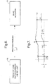
- Alert 5 will be received by following the trend curve of the load factor.
- Figure 6 illustrates condition 16 of the alert 5: the trend of the load factor exceeds a set limit.
- Conclusion 17 is that there is a friction problem, the location 18 of which is either in the valve or in the actuator.
- the range to be considered is from 10 to 90 % of the movement range of the valve.
- Figure 7 illustrates the operation for alert 5, in other words, as function of time the changes of the difference ⁇ p between the input and output pressure of the actuator and the valve position s .
- the initial situation A and its quantities to be stored are determined as in Alert 2. After that the change of the valve position s will be observed. When the change s exceeds by 1 % the value of the initial situation stored into the memory, this situation is determined as the starting point E of the valve, whereby the difference ⁇ p between the input and output pressure of the actuator and the input pressure p s of the positioner will be stored. Load factor k will be calculated from these values. The next balance state A' will be selected as a new initial situation. If the difference between the valve positions in the initial situation A and in the new initial situation A' is bigger than 2 %, the calculated load factor k will be stored in order to edit the trend curve.
- Parameters of alert 5 are a change of > 1 % of the position s compared with the stored value of the initial situation A, load factor k, a change of > 2 % of the position s compared with the stored value of the initial situation A, an alert limit of the load factor trend and the number of exceedings having lead to an alert. Reading cycle is 0,1 s.
- Figure 8 illustrates a trend curve calculated from the average values of several load factors as a function of time and the set alert limit.
Description
- The present invention concerns a method for surveying the condition of a control valve apparatus, the position of which is adjusted by means of an actuator controlled by an electropneumatic positioner and operated by means of pressure medium, whereby the operation of the valve is monitored by sensors that during the valve operation read at certain reading intervals the readings at least from the control signal of the valve, the input pressure of the positioner, the difference between the input and output pressure of the actuator, and the position of the valve, and the fault causing the deviating reading is located by means of a microprocessor by using the readings given by the sensors and deduction rules stored in the microprocessor. EP-A-0 708 389 discloses such a method according to the preamble of
claim 1. - The invention also concerns a control valve apparatus comprising a valve, an actuator driven by means of a cylinder-piston device, and an electropneumatic positioner, sensors for monitoring at least the control signal of the valve, the input pressure of the positioner, the difference between the input and output pressure of the actuator, and the valve position as well as means for storing the information received from the sensors and the deduction rules to be used for locating a fault and for processing the information received from the sensors in accordance with these rules.
- A control valve and its operation are known in the art and there is no need to describe it in more detail in this connection. The valve can be a quarter-rotational or a linear valve, said designations describing the moving direction of the closing element of the valve in the controlling situation. A quarter-rotational valve can be e.g. a ball valve or a butterfly valve. Examples of a ball valve have been described e.g. in US patent publication No. 4,747,578. The valve is operated by means of an actuator that turns the turning shaft of the closing element between the closed and the opened position. The actuator can be driven by means of a cylinder piston device controlled by a pilot valve. This pilot valve is located in the positioner of the control valve. The positioner is a device for amplifying the control signal into the operation pressure of the pneumatic actuator. In the electropneumatic positioner, the electric signal is amplified into the pneumatic operation pressure. The positioner, by means of a feed-back element, also positions the valve to correspond to the control signal.
- The diagnostics of control valves equipped with a pneumatic actuator is in general based on tests performed on the control valves, such as step-function response and hysteresis tests. A requirement for performing the tests is that the process is stopped, whereby the tests are performed at site of the valves. The testing equipment often also includes complicated sensors that can make the testing on the field complicated (US patent publication Nr. 5,197,328). This is so called off-line diagnostics.
- The diagnostics can also be performed on-line, whereby the positioner of the control valve monitors e.g. the position message of the valve and gives an alert if the position message deviates too much from the value presupposed by the control system. Part of the on-line diagnostics are also the operation counters of the valve that give an alert when the number of the operations exceeds a certain predetermined limit. This diagnostics system, however, does not include any deduction procedure by which the faults could be located.
- In both of the US patent publications No. 5,329,465 and No. 4,694,390, valves have been described, in the control system of which separate measuring sensors are used. The inventions described in the publications concern an on-off regulation of the valve, not continuous controlling.
- In the system according to US patent publication No. 5,329,465, sensors are used for condition surveying of the valve and for collecting historical data for the data base. The fault analysis is made by comparing the measured values with the values collected earlier for the data base. The position of the valve is not adjusted continuously but the valve is moving only when it is closed or opened. This can happen a couple of times per day or the adjustment interval can even be several months. The values required for the fault analysis are monitored only during this opening and closing movement that happens at long intervals.
- A method in accordance with the present invention is characterized in that
- for locating a fault, the same readings given by the sensors are used, by means of which the valve is controlled;
- in an initial situation when the control valve is in a balance state, i.e. the changes of its position, control signal and the difference between the input and output pressure of the actuator are continuously smaller than certain values at least for a certain period of time, the readings given by the sensors at least from the control signal, the valve position and the difference between the input and output pressure of the actuator are stored;
- when the operation is continued, the readings given by the sensors are compared with the values of the initial situation, and if the deviations exceed certain limit values and remain continuously above these limit values for a certain period of time, a fault message is given that informs the location of the fault.
- An apparatus in accordance with the present invention is characterized in that the deduction rules have been programmed in the microprocessor of a digital positioner, said microprocessor processing the readings of the sensors.
- The invention is directed to an electrically controlled pneumatic system, where the sensors used for controlling operation are also used for fault analysis. Thus, the values are collected from the valve by means of the sensors continuously. The positioning unit includes an integral self-diagnostic part that in a bus-constructed control makes it possible to transmit the information immediately to the control unit or the monitoring room.
- The invention is based on a logic programmed in the digital positioner, based on which the processor of the positioner performs an on-line condition monitoring of the control valve. The quantities to be monitored by the positioner are the control current signal, the difference between the input and output pressure of the actuator, the valve position and the input pressure of the positioner. By continuously monitoring these quantities and by comparing their changes with the rules determined by the logic, the diagnostics tend to locate the faulted object in the control valve. When locating the faulted object by means of the logic, it is the purpose to find out if there is a fault in the positioner (slide), in the pneumatic actuator or in the valve. Additionally, the circuit card of the digital positioner has its own integral diagnostics, by means of which the positioner informs about the faults on the circuit cards. This diagnostics of the circuit card is, however, not a part of the present invention.
- The logical rules are formed of rules, that all must be fulfilled in order to activate the diagnostics to give a fault message. As a result, the diagnostics inform the eventual faulted object.
- The invention concerns the logic of the diagnostics to be programmed into the digital positioner of a control valve. The logic is formed of a deduction mechanism formed by Boolean rules.
- The positioner monitors during the process i.a. the position information of the control valve, the difference between the input and output: pressure of the actuator, the control signal and the level of the input pressure of the positioner. These values and their changes are compared with the deduction rules formed by Boolean rules, based on which the condition of the control valve is noted and, if necessary, alerts are given, by which the eventually faulted components are located (positioner, actuator, valve).
- The deduction rules are divided into five parts giving different alerts, in other words, giving the fault message.
-
Alert 1 is given, when a fault has been found on the circuit card of the positioner (current message, angle sensor, preregulating valves, pressure sensors, EEPROM and ROM memories). This diagnostics are taken care of by separate diagnostics made on the circuit card, the closer contents of which are not an object of the present invention. -
Alert 2 is given, when the control signal of the valve changes, but the difference between the input and output pressure of the actuator, and the position of the valve are not changed. In that case the fault message tells that there is a fault in the operation of the slide of the positioner. -
Alert 3 is given, when the difference quantity between the valve position corresponding to the control signal and the measured valve position exceeds the set limit continuously for a certain time. The fault message tells in that case the most probable objects of the fault. In case it is a friction problem, alsoalert 4 and/oralert 5 can be given. -
Alert 4 is given, when the control signal changes and the difference between the input and output pressure of the actuator increases, but the position of the valve is not changed. In that case, it is a question of a friction problem. -
Alert 5 is given, when the trend of the load factor exceeds a set limit. In that case, it is a question of a friction problem. - When the rules of the fault diagnostics and the deduction mechanism are in the memory of the positioner, information on the eventual indefinite operation of the control valve is received continuously during the process. So, the deduction is not based on tests performed separately, whereby the process would have to be interrupted, but the monitoring of the valve condition is performed and the alerts are given with an on-line system during the process. This is a significant innovation in the condition surveying of pneumatically operated control valves.
- Information on the alerts can be transmitted automatically e.g. through an HART data transfer channel e.g. to a monitoring room. Thus, it is not necessary to pick up the information separately from each valve, the accessibility of which can sometimes be difficult. As it is not necessary to go to the valve in order to get the diagnostics information, also no separate equipment is required for reading the information from the valve on the field. Also no time will be spent for picking up the information.
- It is not necessary to demount the valve from the piping for evaluating its condition, which is a difficult task and takes a lot of time. If alerts are given by the diagnostics, it is possible after this to perform test drives on the valve, if necessary, whereby the eventual objects of the fault can be located even more accurately. In order to perform these test drives the process has to be stopped.
- Receiving continuous on-line information on the condition of control valves is significant from the point of view of preventive maintenance. A valve can operate even a long time indefinitely disturbing the operation of the process before it is serviced. In the worst case the valve can crack up causing expensive production shutdowns. These cases can be avoided, if information on the condition of the valve can be received continuously during the process.
- Traditionally, the maintenance of valves has been maintenance operation to be performed during the outages of the factory, whereby the valves at the most critical points are serviced without knowing their condition in advance. In that case valves can be serviced that would not have needed any service yet, or service of valves that would have needed to be serviced can be neglected, because there is not enough time to service all the valves during the outage. If on-line information is received on the condition of the valves, the valves that need service can be located, and by means of tests a closer diagnostic can be made in order to determine more precisely their factual need of service.
- The final advantage to be gained through the on-line diagnostics is the increasing safety of the process and decreasing of the costs while the feasibility of the process will be increased and the production losses decreased. Energy is saved, wastages are decreased and unpredictable production outages are avoided. Also the size of the spare part stocks can be decreased.
- The invention and its details are described in more detail in the following, with reference to the enclosed drawings, wherein
- Figure 1 illustrates schematically a control valve apparatus in accordance with the present invention,
- Figure 2 illustrates conditions and conclusions of
alert 2, - Figure 3 illustrates as a function of time the quantities
to be monitored for
alert 2, - Figure 4 illustrates conditions and conclusions of
alert 3, - Figure 5 illustrates conditions and conclusions of
alert 4, - Figure 6 illustrates conditions and conclusions of
alert 5, - Figure 7 illustrates quantities to be monitored for
alert 5 and - Figure 8 illustrates a trend curve of the load factor
-
- Figure 1 illustrates an apparatus comprising a
control valve 101, anactuator 103 driven by a cylinder-piston device 102 and apositioner 104. The actuator is controlled by apilot valve 105. Messages of the positioner are processed by a printedcircuit card 106 where the control information is stored in. Asensor 107 measures the position s of a closingmember 108, asensor 109 measures the input pressure ps of the positioner and asensor 110 measures the difference Δp between the input and output pressure of the actuator. These sensors are located in the positioner. The flow of the different electric messages and measurements is marked on the diagram. Control signal i is input in the system. -
Alert 1 indicates a circuit card problem of the positioner, as stated above, but it is not a part of the present invention. -
Alert 2 indicates a slide problem of the control valve. - Figure 2 illustrates as a diagram four different conditions by means of which the deduction concerning the
alert 2 is performed. In figure 3, the operation for thealert 2 is described, that is, the quantities monitored as a function of time and their parameters. Point A is the point of the time axis, where the values of the control signal i, the difference Δp between the input and output pressure of the actuator, and the valve position s to be monitored have for repeating reading cycles been within the given limit values for a required time. The values of the quantities of this balance state A named as "the initial situation", are stored in the registers. If a change of > 5 % occurs in the control signal, the time counter starts. If the signal change returns below the limit of 5 % within a chosen period of time, the time counter is reset to zero and there will be no changes in the other registers if during the change of the control signal i no change of > 1 % has occurred in the valve positions in relation to the value of the initial situation A. In that case, a new initial situation A has to be set. If both the control signal i and the valve position s exceed the values of the balance conditions of the initial situation A, a new initial situation will be searched. - Condition 1: A change of more than 5 % of the control signal i lasts more than 120 s, in other words, from point B to point D in figure 3.
- Condition 2: A change of the difference Δp between the input and output pressure of the actuator is within the predetermined limits, in figure 3 the change is < 0,2 bar in the period of time A → B and from B to C.
- Condition 3: A change of the valve position s is within the predetermined limits, in figure 3 the change < 1 % in the period of time A → B and from B to C.
- Condition 4: No
ALERT 1. - Based on this data,
conclusion 5 will be reached: the slide of the pilot valve is stuck, whereby the location of thefault 6 is in the positioner. - The range to be considered is from 10 to 90 % of the movement range of the control valve, in other words, the most extreme starting and ending positions of the movement range are not considered.
- In the example of figure 3, a change of ≤ 2 % of the control signal i and duration of 10 s; a
change ≤ - The corresponding parameters of the alert state are: a change of > 5 % of the control signal i and time of 120 s, in other words on the time axis from B to D; a change of ≤ 0,2 % of the difference Δp of the input and output pressure, and time of 30 s, in other words on the time axis from B to C; and a change of ≤ 1 % of the position s and time of 120 s, i.e. from B to D. Naturally also other parameter values can be selected according to need. From the alerts, the first and the last one will be stored as well as their times of occurence and the total number of the alerts. The reading cycle is 0,1 s.
-
Alert 3 means a big quantity of difference between the control signal and the valve position. - Figure 4 illustrates the condition of the
alert 3 and the conclusion. - Condition 7: The quantity of difference between the valve position corresponding to the signal and the measured valve position is > 5 % continuously for more than 10 minutes.
-
Conclusion 8 is that this means either, that - the fore choke of the positioner for reducing the input pressure of the compressed air fed to the electropneumatic positioner, so that it is suitable for electric control, is blocked, or
- the plane seal of the slide unit of the pilot valve leaks, or
- there is an internal or external leakage in the cylinder of the actuator, or
- there is a friction problem in the actuator or valve.
- The location 9 of the fault is in the positioner, actuator or valve.
- The range to be considered is from 10 to 90 % of the movement range of the valve.
- Parameters are selected to be the same as the above mentioned values of the
condition 7, that is, the quantity of difference of > 5 % and duration of 10 minutes. From the alerts the first and the last one, their times of occurence and the total number of the alerts are stored. The reading cycle is 0,1 s. -
Alert 4 means a friction problem. - Figure 5 illustrates the four conditions of the
alert 4 and the conclusions. - Condition 10: a change of more than 5 % of the
control signal 1 lasts for more than 120 s, in figure 3 from point B to point D. - Condition 11: a change of the difference Δp of the input and output pressure of the actuator is more than 0,2 bar for 30 s, in figure 3 from point B to point C.
- Condition 12: a change of the valve position s is within the selected limits, in figure 3 the change is < 1 % in the period of time from A to B and from B to D.
- Condition 13: No
ALERT 1. - When these conditions are fulfilled, the conclusion 14 is that there is a friction problem, the
location 15 of which is either in the valve or in the actuator. - The range to be considered is from 10 to 90 % of the movement range of the valve.
- The initial situation A and its quantities to be stored are the same as in Alert 2 (figure 3). The operation is the same as in
Alert 2, except that in this case the difference between the input and output pressure has to change, whereas inAlert 2, this difference had to be unchanged. - As parameters of the alert state, the above mentioned values of the conditions from 10 to 12 have been selected, in other words, a change of > 5 % of the control signal i and time of 120 s; a change of > 0,2 bar of the difference Δp between the input and output pressure of the actuator and time of 30 s; and a change of ≤ 1 % of the position s of the regulating valve and
time 120 s. - From the alerts the first and the last one will be stored, their times of occurence and the total number of the alerts. The reading cycle is 0,1 s.
-
Alert 5 will be received by following the trend curve of the load factor. - Figure 6 illustrates
condition 16 of the alert 5: the trend of the load factor exceeds a set limit.Conclusion 17 is that there is a friction problem, thelocation 18 of which is either in the valve or in the actuator. - The range to be considered is from 10 to 90 % of the movement range of the valve.
- Figure 7 illustrates the operation for
alert 5, in other words, as function of time the changes of the difference Δp between the input and output pressure of the actuator and the valve position s. The initial situation A and its quantities to be stored are determined as inAlert 2. After that the change of the valve position s will be observed. When the change s exceeds by 1 % the value of the initial situation stored into the memory, this situation is determined as the starting point E of the valve, whereby the difference Δp between the input and output pressure of the actuator and the input pressure ps of the positioner will be stored. Load factor k will be calculated from these values. The next balance state A' will be selected as a new initial situation. If the difference between the valve positions in the initial situation A and in the new initial situation A' is bigger than 2 %, the calculated load factor k will be stored in order to edit the trend curve. - An alert will be given when five consecutive measurements exceed a set limit.
- Load factor k of the actuator will be obtained from the following formula:
- ΔpL =
- the difference between the input and output pressure of the actuator at the starting point of the valve
- ps =
- the input pressure of the positioner
- Parameters of
alert 5 are a change of > 1 % of the position s compared with the stored value of the initial situation A, load factor k, a change of > 2 % of the position s compared with the stored value of the initial situation A, an alert limit of the load factor trend and the number of exceedings having lead to an alert. Reading cycle is 0,1 s. - Figure 8 illustrates a trend curve calculated from the average values of several load factors as a function of time and the set alert limit.
Claims (3)
- A method for surveying the condition of a control valve apparatus, in which the position of the closing element (108) of the valve (101) is adjusted by means of an actuator (103) controlled by an electropneumatic positioner (104) and operated by means of pressure medium, whereby the operation of the valve is monitored by sensors that during the valve operation read at certain reading intervals the readings at least from the control signal (i) of the valve, the input pressure (ps) of the positioner, the difference (Δp) between the input and output pressure of the actuator, and the position (s) of the valve, and the fault causing a deviating reading is located by means of a microprocessor by using the readings given by the sensors and deduction rules stored in the microprocessor, wherebythenfor locating the fault, the same readings given by the sensors are used, by means of which the valve is controlled;in an initial situation (A), whereby the control valve (101) is in a balance state, i.e. the changes of its position (s), control signal (i) and the difference (Δp) between the input and output pressure of the actuator are continuously smaller than certain values at least for a certain period of time, the readings given by the sensors at least from the control signal (i), the valve position (s) and the difference (Δp) between the input and output pressure of the actuator are stored;when the operation is continued, the readings given by the sensors are compared with the readings of the initial situation (A), and if the deviations exceed certain limit values and remain continuously above these limit values for a certain period of time, a fault message is given that informs about the location of the fault, characterized in thatwhen the operation is continued from the initial situation (A), the readings given by the sensors are compared with the readings of the initial situation (A), and ifthe change of the control signal (i) at a certain moment (B) exceeds a certain limit value and remains above this limit value for a certain period of time (B → D) ; andthe change of the valve position (s) is smaller than the respective certain value of the initial situation (A) for a period of time (A → D) starting from the initial situation (A) and continuing for a certain period of time (B → D), during which the change of the control signal (i) remains above its limit value mentioned above; andno fault message occurs, that would have been caused by certain faults indicated by means of the circuit card of the positioner;a) when the change of the difference (Δp) between the input and output pressure of the actuator is smaller than a certain value of the balance state of the initial situation (A) for a certain period of time (B → C), which is included in said period of time (B → D) during which the change of the control signal (i) remains above said limit value of it;
a fault message is given that informs that the fault is located in the pilot valve (105) of the positioner (104);
orb) when the change of the difference (Δp) between the input and output pressure of the actuator is bigger than a certain value of the balance state of the initial situation (A) for a certain period of time (B → C), which is included in the period of time (B → D), during which the signal change remains above said limit value of it;
a fault message is given that indicates that the fault is loocated in the valve (101) or in the actuator (103). - A method in accordance with claim 1, characterized in that the first and the last of several consecutive fault messages are stored, as well as the times of occurence of these two fault messages and the number of all consecutive fault messages.
- A method in accordance with claim 1 or 2, characterized in thatwhen the operation of the valve is continued from the balance state of the initial situation (A) to the next balance state (A'), in which the valve position (s) has changed at least for a certain amount, the reading given by the position sensor (107) is compared during this period of time (A → A') with the stored reading of the initial situation (A), and when the difference of said readings exceeds a certain value, the reading of the difference (Δp) of the input and output pressure of the actuator and the reading of the input pressure (ps) of the positioner are read at the respective moment (E) and from the ratio of these readings a loading factor (k) is calculated and stored in the memory; andwhen the loading factor (k) exceeds a certain limit and the number of exceedings or the average value of a certain number of the exceedings reaches a certain value, a fault message is given indicating that the fault is the friction in the valve (101) or in the actuator (103).
Applications Claiming Priority (3)
| Application Number | Priority Date | Filing Date | Title |
|---|---|---|---|
| FI962406A FI104129B (en) | 1996-06-11 | 1996-06-11 | Procedure for monitoring the condition of control valve |
| FI962406 | 1996-06-11 | ||
| PCT/FI1997/000359 WO1997048026A2 (en) | 1996-06-11 | 1997-06-09 | A method for surveying the condition of a control valve, and a valve apparatus |
Publications (2)
| Publication Number | Publication Date |
|---|---|
| EP0904573A2 EP0904573A2 (en) | 1999-03-31 |
| EP0904573B1 true EP0904573B1 (en) | 2001-10-17 |
Family
ID=8546182
Family Applications (1)
| Application Number | Title | Priority Date | Filing Date |
|---|---|---|---|
| EP97926021A Expired - Lifetime EP0904573B1 (en) | 1996-06-11 | 1997-06-09 | A method for surveying the condition of a control valve, and a valve apparatus |
Country Status (7)
| Country | Link |
|---|---|
| US (1) | US6131609A (en) |
| EP (1) | EP0904573B1 (en) |
| JP (1) | JP3885118B2 (en) |
| DE (1) | DE69707449T2 (en) |
| ES (1) | ES2168638T3 (en) |
| FI (1) | FI104129B (en) |
| WO (1) | WO1997048026A2 (en) |
Cited By (1)
| Publication number | Priority date | Publication date | Assignee | Title |
|---|---|---|---|---|
| CN102308135A (en) * | 2009-01-09 | 2012-01-04 | 美卓自动化有限公司 | Method and apparatus for condition monitoring of valve |
Families Citing this family (48)
| Publication number | Priority date | Publication date | Assignee | Title |
|---|---|---|---|---|
| FI116587B (en) | 1997-10-17 | 2005-12-30 | Metso Automation Oy | Method and apparatus for verifying the proper functioning of the restraint |
| JP3511458B2 (en) * | 1997-12-08 | 2004-03-29 | 株式会社山武 | Electro-pneumatic positioner |
| JP3530775B2 (en) * | 1999-07-16 | 2004-05-24 | Smc株式会社 | Solenoid valve operation management device |
| DE20005744U1 (en) * | 2000-03-28 | 2000-10-05 | Icops Ind & Cyber Operation Se | Valve monitoring device |
| US6640688B1 (en) | 2000-08-25 | 2003-11-04 | Tyco Flow Control, Inc. | Actuator assembly |
| US6435022B1 (en) * | 2001-02-09 | 2002-08-20 | Tareq Nasser Albuaijan | Partial stroke testing system |
| US6382226B1 (en) * | 2001-04-17 | 2002-05-07 | Fisher Controls International, Inc. | Method for detecting broken valve stem |
| EP1440267B1 (en) * | 2001-11-01 | 2005-09-28 | Shell Internationale Researchmaatschappij B.V. | Over-pressure protection system |
| US6678584B2 (en) | 2002-05-03 | 2004-01-13 | Fisher Controls International Llc | Method and apparatus for performing diagnostics in a control loop of a control valve |
| US6999853B2 (en) * | 2002-05-03 | 2006-02-14 | Fisher Controls International Llc. | Methods and apparatus for operating and performing diagnostics in a control loop of a control valve |
| US7044011B2 (en) * | 2003-04-30 | 2006-05-16 | Honeywell International, Inc. | Test fixture assembly for directional pilot valve and related method |
| US7124057B2 (en) * | 2003-08-19 | 2006-10-17 | Festo Corporation | Method and apparatus for diagnosing a cyclic system |
| EP1711872A1 (en) * | 2004-02-05 | 2006-10-18 | Rosemount, Inc. | Emergency shutdown valve diagnostics using a pressure transmitter |
| US7504961B2 (en) * | 2005-03-31 | 2009-03-17 | Saudi Arabian Oil Company | Emergency isolation valve controller with integral fault indicator |
| US8072343B2 (en) * | 2005-03-31 | 2011-12-06 | Saudi Arabian Oil Company | Local emergency isolation valve controller with diagnostic testing and trouble indicator |
| DE102005028810A1 (en) | 2005-06-22 | 2007-01-04 | Robert Bosch Gmbh | Method for the automated testing of a controller |
| US20070034264A1 (en) * | 2005-08-12 | 2007-02-15 | Stonel Corporation | Apparatus for valve communication and control |
| US8366402B2 (en) * | 2005-12-20 | 2013-02-05 | Schlumberger Technology Corporation | System and method for determining onset of failure modes in a positive displacement pump |
| US7405917B2 (en) * | 2006-06-16 | 2008-07-29 | Festo Ag & Co. | Method and apparatus for monitoring and determining the functional status of an electromagnetic valve |
| US7539560B2 (en) * | 2007-01-05 | 2009-05-26 | Dresser, Inc. | Control valve and positioner diagnostics |
| US7975718B2 (en) * | 2007-04-16 | 2011-07-12 | Applied Materials, Inc. | In-situ monitor of injection valve |
| US7752914B2 (en) * | 2007-11-15 | 2010-07-13 | Venturedyne, Ltd. | Monitoring of independent vibrators |
| US8955365B2 (en) * | 2008-12-23 | 2015-02-17 | Embraer S.A. | Performance monitoring and prognostics for aircraft pneumatic control valves |
| US20100264868A1 (en) * | 2009-04-15 | 2010-10-21 | Stephen George Seberger | Methods and apparatus to couple an electro-pneumatic controller to a position transmitter in a process control system |
| WO2010140930A1 (en) * | 2009-06-02 | 2010-12-09 | Linde Ag | Diagnostic system for a flow valve in an industrial furnace |
| US8453674B2 (en) * | 2010-03-12 | 2013-06-04 | Target Rock Division Of Curtiss-Wright Flow Control Corporation | Valve fault indication and control |
| GB2480423A (en) * | 2010-03-15 | 2011-11-23 | Jena Rotary Technolgy Ltd | Valve system |
| CN103038559B (en) * | 2010-04-30 | 2015-08-19 | 美卓自动化有限公司 | The diagnosis of control valve |
| CN102384303B (en) * | 2010-08-31 | 2014-11-26 | 金子产业株式会社 | Cutoff valve control system |
| US8421643B2 (en) * | 2010-12-01 | 2013-04-16 | Fisher Controls International Llc | Automatic valve seating integrity test |
| US8973595B2 (en) * | 2011-08-01 | 2015-03-10 | Control Microsystems, Inc. | Battery-powered control valve and operation thereof |
| US8924028B2 (en) | 2011-08-01 | 2014-12-30 | Control Microsystems, Inc. | Battery-powered control valve and operation thereof |
| AU2011374287B2 (en) * | 2011-08-01 | 2017-07-20 | Schneider Electric Systems Canada Inc. | Battery-powered control valve and operation thereof |
| DE102011052901B4 (en) * | 2011-08-22 | 2020-07-09 | Samson Ag | Partial stoke test for an actuator |
| US9250632B2 (en) * | 2011-12-30 | 2016-02-02 | Sti Srl | Valve positioning system with bleed prevention |
| US9170238B2 (en) * | 2013-01-04 | 2015-10-27 | Fisher Controls International Llc | Acoustic fluid valve calibration |
| US9309992B2 (en) * | 2013-03-15 | 2016-04-12 | Sdb Ip Holdings, Llc | System for detecting that a valve should be replaced and a method of use thereof |
| JP6088457B2 (en) * | 2014-03-11 | 2017-03-01 | アズビル株式会社 | Positioner |
| GB2528891A (en) * | 2014-08-01 | 2016-02-10 | Chargepoint Technology Ltd | Operator feedback of valves |
| US9933088B2 (en) * | 2015-06-10 | 2018-04-03 | Woodward, Inc. | Rotary actuated valve with position indicator |
| US10557564B2 (en) * | 2017-01-07 | 2020-02-11 | Saudi Arabian Oil Company | Locally-actuated partial stroke testing system |
| FI128783B (en) * | 2018-09-03 | 2020-12-15 | Metso Flow Control Oy | Valve positioner and diagnostic method |
| JP6783486B1 (en) * | 2020-03-17 | 2020-11-11 | 金子産業株式会社 | Machine learning equipment, data processing systems, inference equipment and machine learning methods |
| CN111350870A (en) * | 2020-03-18 | 2020-06-30 | 中石化第十建设有限公司 | Control valve air source failure detection equipment calibration method |
| US11788934B2 (en) | 2020-07-01 | 2023-10-17 | Saudi Arabian Oil Company | In-line fluid and solid sampling within flowlines |
| US11441697B2 (en) | 2020-10-01 | 2022-09-13 | Saudi Arabian Oil Company | Valve diagnostic and performance system |
| US11692903B2 (en) | 2020-10-01 | 2023-07-04 | Saudi Arabian Oil Company | Valve diagnostic and performance system |
| US11865928B2 (en) | 2021-11-24 | 2024-01-09 | Saudi Arabian Oil Company | Generating power with a conduit inspection tool |
Family Cites Families (19)
| Publication number | Priority date | Publication date | Assignee | Title |
|---|---|---|---|---|
| US4029122A (en) * | 1976-03-11 | 1977-06-14 | Westinghouse Electric Corporation | Apparatus and method for determining friction forces in position modulated valves |
| US4274438A (en) * | 1979-02-21 | 1981-06-23 | Westinghouse Electric Corp. | Method of diagnostic valve testing |
| US4523286A (en) * | 1981-08-07 | 1985-06-11 | Hitachi, Ltd. | Apparatus for making diagnosis of valve device in turbine system |
| US4694390A (en) * | 1985-06-28 | 1987-09-15 | Electric Power Research Institute, Inc. | Microprocessor-based control and diagnostic system for motor operated valves |
| FI72584C (en) * | 1985-09-04 | 1987-06-08 | Neles Oy | VENTIL. |
| GB8620357D0 (en) * | 1986-08-21 | 1986-10-01 | Apv Int Ltd | Flow control valve |
| KR890007306A (en) * | 1987-10-30 | 1989-06-19 | 제트.엘.더머 | Online valve diagnostic monitoring system |
| US5197328A (en) * | 1988-08-25 | 1993-03-30 | Fisher Controls International, Inc. | Diagnostic apparatus and method for fluid control valves |
| US4926903A (en) * | 1989-05-05 | 1990-05-22 | Tomoe Technical Research Company | Butterfly valve having a function for measuring a flow rate and method of measuring a flow rate with a butterfly valve |
| US5253185A (en) * | 1991-01-30 | 1993-10-12 | Combustion Engineering, Inc. | Valve diagnostic system including auxiliary transducer box |
| US5492009A (en) * | 1991-03-11 | 1996-02-20 | Siemens Aktiengesellschaft | Method and apparatus for testing a valve actuated by an electromagnet having an armature |
| US5329956A (en) * | 1993-05-28 | 1994-07-19 | Combustion Engineering, Inc. | Pneumatic operated valve stroke timing |
| DE4326343A1 (en) * | 1993-08-05 | 1995-02-09 | Honeywell Ag | Diganose system for control and shut-off valves |
| US5549137A (en) * | 1993-08-25 | 1996-08-27 | Rosemount Inc. | Valve positioner with pressure feedback, dynamic correction and diagnostics |
| AU7634494A (en) * | 1993-09-15 | 1995-04-03 | Combustion Engineering Inc. | Diagnostic data acquisitioner for a valve |
| US5469737A (en) * | 1993-12-20 | 1995-11-28 | Westinghouse Electric Corporation | Method and apparatus for measuring the axial load and position of a valve stem |
| IT1265319B1 (en) * | 1993-12-22 | 1996-10-31 | Nuovo Pignone Spa | IMPROVED CONTROL SYSTEM FOR THE ACTUATOR OF A PNEUMATIC VALVE |
| DE69515096T2 (en) * | 1994-10-18 | 2000-07-20 | Neles Controls Oy Helsinki | Method and device for determining a fault in a control valve arrangement in a control loop |
| US5992229A (en) * | 1996-02-05 | 1999-11-30 | Neles-Jamesbury Oy | Method and equipment for determining the performance of control valve |
-
1996
- 1996-06-11 FI FI962406A patent/FI104129B/en active
-
1997
- 1997-06-09 US US09/202,201 patent/US6131609A/en not_active Expired - Fee Related
- 1997-06-09 EP EP97926021A patent/EP0904573B1/en not_active Expired - Lifetime
- 1997-06-09 JP JP50124998A patent/JP3885118B2/en not_active Expired - Fee Related
- 1997-06-09 WO PCT/FI1997/000359 patent/WO1997048026A2/en active IP Right Grant
- 1997-06-09 DE DE69707449T patent/DE69707449T2/en not_active Expired - Fee Related
- 1997-06-09 ES ES97926021T patent/ES2168638T3/en not_active Expired - Lifetime
Cited By (2)
| Publication number | Priority date | Publication date | Assignee | Title |
|---|---|---|---|---|
| CN102308135A (en) * | 2009-01-09 | 2012-01-04 | 美卓自动化有限公司 | Method and apparatus for condition monitoring of valve |
| CN102308135B (en) * | 2009-01-09 | 2014-10-15 | 美卓自动化有限公司 | Method and apparatus for condition monitoring of valve |
Also Published As
| Publication number | Publication date |
|---|---|
| ES2168638T3 (en) | 2002-06-16 |
| FI104129B1 (en) | 1999-11-15 |
| JP2001522482A (en) | 2001-11-13 |
| US6131609A (en) | 2000-10-17 |
| FI104129B (en) | 1999-11-15 |
| FI962406A0 (en) | 1996-06-11 |
| EP0904573A2 (en) | 1999-03-31 |
| DE69707449T2 (en) | 2002-11-14 |
| JP3885118B2 (en) | 2007-02-21 |
| WO1997048026A3 (en) | 1998-02-05 |
| DE69707449D1 (en) | 2001-11-22 |
| WO1997048026A2 (en) | 1997-12-18 |
| FI962406A (en) | 1998-01-05 |
Similar Documents
| Publication | Publication Date | Title |
|---|---|---|
| EP0904573B1 (en) | A method for surveying the condition of a control valve, and a valve apparatus | |
| JP4088160B2 (en) | Valve stem breakage detection method | |
| US7890216B2 (en) | Control valve and positioner diagnostics | |
| US8768631B2 (en) | Diagnostic method for detecting control valve component failure | |
| RU2106561C1 (en) | Method and device for check of medium-actuated fittings | |
| US5966679A (en) | Method of and apparatus for nonobtrusively obtaining on-line measurements of a process control device parameter | |
| EP2118544B1 (en) | Fluid regulatory system and process | |
| WO2010079260A1 (en) | Method and apparatus for condition monitoring of valve | |
| CN114729708A (en) | Electromagnetic valve | |
| WO2002017028A1 (en) | Method for detecting plug wear | |
| Kiesbauer et al. | Modern control valves with failure diagnostics | |
| JPH07239717A (en) | Method for automatic adjustment of operation range of servo controller | |
| JPS60116806A (en) | Abnormality diagnosing device of hydraulic type valve driving device |
Legal Events
| Date | Code | Title | Description |
|---|---|---|---|
| PUAI | Public reference made under article 153(3) epc to a published international application that has entered the european phase |
Free format text: ORIGINAL CODE: 0009012 |
|
| 17P | Request for examination filed |
Effective date: 19981207 |
|
| AK | Designated contracting states |
Kind code of ref document: A2 Designated state(s): DE ES FI FR GB IT SE |
|
| GRAG | Despatch of communication of intention to grant |
Free format text: ORIGINAL CODE: EPIDOS AGRA |
|
| 17Q | First examination report despatched |
Effective date: 20001221 |
|
| GRAG | Despatch of communication of intention to grant |
Free format text: ORIGINAL CODE: EPIDOS AGRA |
|
| GRAH | Despatch of communication of intention to grant a patent |
Free format text: ORIGINAL CODE: EPIDOS IGRA |
|
| GRAH | Despatch of communication of intention to grant a patent |
Free format text: ORIGINAL CODE: EPIDOS IGRA |
|
| GRAA | (expected) grant |
Free format text: ORIGINAL CODE: 0009210 |
|
| AK | Designated contracting states |
Kind code of ref document: B1 Designated state(s): DE ES FI FR GB IT SE |
|
| PG25 | Lapsed in a contracting state [announced via postgrant information from national office to epo] |
Ref country code: FI Free format text: LAPSE BECAUSE OF FAILURE TO SUBMIT A TRANSLATION OF THE DESCRIPTION OR TO PAY THE FEE WITHIN THE PRESCRIBED TIME-LIMIT Effective date: 20011017 |
|
| REF | Corresponds to: |
Ref document number: 69707449 Country of ref document: DE Date of ref document: 20011122 |
|
| REG | Reference to a national code |
Ref country code: GB Ref legal event code: IF02 |
|
| RAP2 | Party data changed (patent owner data changed or rights of a patent transferred) |
Owner name: METSO FIELD SYSTEMS OY |
|
| ET | Fr: translation filed | ||
| REG | Reference to a national code |
Ref country code: GB Ref legal event code: 732E |
|
| REG | Reference to a national code |
Ref country code: ES Ref legal event code: PC2A Ref country code: ES Ref legal event code: FG2A Ref document number: 2168638 Country of ref document: ES Kind code of ref document: T3 |
|
| PLBE | No opposition filed within time limit |
Free format text: ORIGINAL CODE: 0009261 |
|
| STAA | Information on the status of an ep patent application or granted ep patent |
Free format text: STATUS: NO OPPOSITION FILED WITHIN TIME LIMIT |
|
| 26N | No opposition filed | ||
| PGFP | Annual fee paid to national office [announced via postgrant information from national office to epo] |
Ref country code: ES Payment date: 20080627 Year of fee payment: 12 |
|
| PGFP | Annual fee paid to national office [announced via postgrant information from national office to epo] |
Ref country code: IT Payment date: 20080625 Year of fee payment: 12 |
|
| PGFP | Annual fee paid to national office [announced via postgrant information from national office to epo] |
Ref country code: SE Payment date: 20080612 Year of fee payment: 12 Ref country code: DE Payment date: 20080620 Year of fee payment: 12 |
|
| PGFP | Annual fee paid to national office [announced via postgrant information from national office to epo] |
Ref country code: FR Payment date: 20080613 Year of fee payment: 12 |
|
| PGFP | Annual fee paid to national office [announced via postgrant information from national office to epo] |
Ref country code: GB Payment date: 20080620 Year of fee payment: 12 |
|
| GBPC | Gb: european patent ceased through non-payment of renewal fee |
Effective date: 20090609 |
|
| REG | Reference to a national code |
Ref country code: FR Ref legal event code: ST Effective date: 20100226 |
|
| PG25 | Lapsed in a contracting state [announced via postgrant information from national office to epo] |
Ref country code: FR Free format text: LAPSE BECAUSE OF NON-PAYMENT OF DUE FEES Effective date: 20090630 |
|
| PG25 | Lapsed in a contracting state [announced via postgrant information from national office to epo] |
Ref country code: GB Free format text: LAPSE BECAUSE OF NON-PAYMENT OF DUE FEES Effective date: 20090609 |
|
| PG25 | Lapsed in a contracting state [announced via postgrant information from national office to epo] |
Ref country code: DE Free format text: LAPSE BECAUSE OF NON-PAYMENT OF DUE FEES Effective date: 20100101 |
|
| REG | Reference to a national code |
Ref country code: ES Ref legal event code: FD2A Effective date: 20090610 |
|
| PG25 | Lapsed in a contracting state [announced via postgrant information from national office to epo] |
Ref country code: ES Free format text: LAPSE BECAUSE OF NON-PAYMENT OF DUE FEES Effective date: 20090610 |
|
| PG25 | Lapsed in a contracting state [announced via postgrant information from national office to epo] |
Ref country code: IT Free format text: LAPSE BECAUSE OF NON-PAYMENT OF DUE FEES Effective date: 20090609 |
|
| PG25 | Lapsed in a contracting state [announced via postgrant information from national office to epo] |
Ref country code: SE Free format text: LAPSE BECAUSE OF NON-PAYMENT OF DUE FEES Effective date: 20090610 |