EP0904698A1 - Method and device for tying tubular casings - Google Patents
Method and device for tying tubular casings Download PDFInfo
- Publication number
- EP0904698A1 EP0904698A1 EP98203064A EP98203064A EP0904698A1 EP 0904698 A1 EP0904698 A1 EP 0904698A1 EP 98203064 A EP98203064 A EP 98203064A EP 98203064 A EP98203064 A EP 98203064A EP 0904698 A1 EP0904698 A1 EP 0904698A1
- Authority
- EP
- European Patent Office
- Prior art keywords
- packaging
- displacement
- filling
- closing
- sleeve
- Prior art date
- Legal status (The legal status is an assumption and is not a legal conclusion. Google has not performed a legal analysis and makes no representation as to the accuracy of the status listed.)
- Granted
Links
Images
Classifications
-
- A—HUMAN NECESSITIES
- A22—BUTCHERING; MEAT TREATMENT; PROCESSING POULTRY OR FISH
- A22C—PROCESSING MEAT, POULTRY, OR FISH
- A22C11/00—Sausage making ; Apparatus for handling or conveying sausage products during manufacture
- A22C11/02—Sausage filling or stuffing machines
Definitions
- the invention relates to a method for closing with with viscous contents filled, tubular or bag-shaped packaging sleeves, in which a Plait-free braid by constricting the packaging envelope at a constricted point produced and at the same time displacing the filling material located there Setting two locking clips is closed.
- the invention relates also a closing device with a displacer.
- the displacer is usually behind the Mouth of the filling pipe of a filling machine arranged.
- the packaging envelope is closed on one side and pulled onto the filling pipe so that the closed End of the packaging envelope is located in front of the filling pipe mouth.
- the filling material is closed through the filling pipe into the one-sided Packaging sleeve pressed. Additional packaging material from deducted from a supply on the filling tube. This peeling of packaging material a casing brake counteracts from the supply on the filling pipe, which the packaging envelope near the filling pipe mouth on the outer surface of the Filler tube presses and brakes in this way. Due to the braking force of the intestinal brake, which are overcome by the filling pressure when filling the packaging envelope the level of the filling pressure is determined.
- a displacer This can be a displacement flap or an expander with two displacement scissors be.
- the packaging envelope to be closed is placed behind the filling pipe mouth of two initially adjacent displacement shears constricted so that a short plait free of filling material is created. Subsequently the two displacement scissors are used to extend the plait free of filling spread, that is, the displacement shear distant from the filling tube is separated from the filling tube Displacement scissors moved away in the longitudinal direction of the filling pipe. The two displacement scissors are spread so far that the resulting plait is sufficient is long to be closed with two locking clips. After the Locking clips are set and locked, the braid can be between the be cut through both locking clips. The packaging envelope just filled is thus closed at both ends while the next one to be filled Packaging sleeve is closed at one end.
- the displacer can only fill the filled packaging Constrict difficulties. It is just as difficult with a spreader subsequent spreading of the displacement shears to extend the filling-free Braid. Especially for packaging sleeves with a diameter of more than 30 mm there is a risk that the packaging envelope when constricting and spreading porous spots or even cracks. Even if it's just a lot minor injuries can be caused by this air and moisture in the Enter the packaging sleeve, which depending on the type of product to harden can lead.
- viscous contents e.g. Sealants, putties, bitumen, silicone, polyurethane and similar substances
- the invention is therefore based on the object, the disadvantages of the prior art Technology through a new process or a new device if possible largely avoided.
- additional packaging sleeve material is withdrawn from a supply. To this This prevents the packaging envelope from being compressed is stretched excessively because excessive stretching could already result in one Damage to the packaging envelope.
- the solution to the above object also consists in one Closing device of the type mentioned, which an additional Clamping device for compressing the packaging next to the displacer having.
- the invention can be Carry out procedures with all its advantages.
- the clamping device preferably has squeeze skids or squeeze rollers on which can be pressed onto the packaging sleeve. Due to the shape of the crushing skids or nip rolls is the shape of the compressed Packaging envelope determined. This is especially true for the length over which the Packaging sleeve is compressed. Have nip rollers if they are rotatably mounted, the further advantage that they can be tightened by additional Lighten the packaging material during compression.
- the squeeze skids or rollers are one in the wake of the outlet Filling machine arranged closing device preferably between the Filling machine and the displacer can be pressed onto the packaging sleeve.
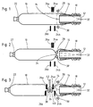
- Figures 1 to 3 show only the essential, when filling and closing a tubular packaging sleeve 10 involved components of a Filling machine and a sealing machine. On the filling machine side, this is First of all, a filling pipe 12 with an opening 14 is in the vicinity of the opening 14 a casing brake 16 pushed onto the filling pipe.
- the packaging envelope 10 closed on one side with a closure clip 22 is with its open end over the casing brake 16 on the lateral surface of the filling tube 12 slipped over there and forms a caterpillar-shaped supply 18
- Filling the packaging envelope 10 is filling material through the filling tube 12 in the one side sealed packaging sleeve 10 pressed.
- This is constantly packaging material drawn from the stock 18.
- Pulling packaging material from the supply 18, the casing brake 16 counteracts, so that Tightening packaging material is a force required by the Filling pressure applied when filling the filling material into the packaging sleeve 10 must become.
- the packaging sleeve 10 As soon as the packaging sleeve 10 is sufficiently filled, it must also be on its second end to be closed. This is used in the exemplary embodiment Spreading displacer with two displacement shears 24 and 26, each consisting of an upper scissor half 24a or 26a and a lower scissor half 24b and 26b.
- two squeeze rollers 28 and 30 are provided, one around common pivot point 32 pivoted and on the outside of the Packaging sleeve 10 can be pressed. This creates a pinch point 34 in the package, the dimension of which over the swivel angle of the squeeze rollers 28 and 30 is adjustable.
- the filling material is removed from the emerging squeeze point 34 displaced and packaging material from the Supply 18 retightened because 34 additional to create the pinch point Shell material is required.
- Retightening the additional packaging material required is facilitated in that the squeeze rollers 28 and 30 are rotatable and can roll on the packaging sleeve 10. In this way the load on the packaging sleeve 10 when compressed is very low.
- the Squeeze point 34 is finally between the displacement shear closer to the filling tube 24 and the filling pipe mouth 14. This state is shown in Figure 2.
- the pinch rollers 28 and 30 swung back to their starting position.
- the pinch point 34 remains usually received.
- the packaging envelope 10 after Squeeze together and then swing away the squeeze rollers 28 and 30 slack at the pinch point 34 and only loosely filled. With that they are Prerequisites created for the two displacement shears 24 and 26 can easily constrict the packaging envelope 10 when closing. While closing the two displacement shears 24 and 26 are immediately adjacent. By Constricting the packaging sleeve 10, they produce a short braid free of filling, the length of which is not sufficient to close it by placing two locking clips close.
- the braid 36 is between the two locking clips 38 and 40 severed with a cutting knife 42.
- the result is just now filled packaging closed at both ends and tubular from the rest Packaging sleeve 10 separately. This is - as requested - on yours one end located in front of the filler pipe mouth 14 and can, as already described, can be filled.
- the displacement shears 24 and 26 become this moved back to their starting position shown in Figure 1.
- the separating knife 42 is swung back again.
Abstract
Description
Die Erfindung betrifft ein Verfahren zum Verschließen Von mit zähem Füllgut befüllten, schlauch- oder beutelförmigen Verpackungshüllen, bei dem ein füllgutfreier Zopf durch Einschnüren der Verpackungshülle an einer Einschnürstelle unter gleichzeitigem Verdrängen dort befindlichen Füllgutes erzeugt und durch Setzen zweier Verschlußklammern verschlossen wird. Die Erfindung betrifft außerdem eine Verschließvorrichtung mit einem Verdränger.The invention relates to a method for closing with with viscous contents filled, tubular or bag-shaped packaging sleeves, in which a Plait-free braid by constricting the packaging envelope at a constricted point produced and at the same time displacing the filling material located there Setting two locking clips is closed. The invention relates also a closing device with a displacer.
Es ist bekannt, befüllte schlauch- oder beutelförmige Verpackungshüllen mit Hilfe eines Verdrängers zu verschließen. Der Verdränger ist üblicherweise hinter der Mündung des Füllrohres einer Füllmaschine angeordnet. Die Verpackungshülle ist einseitig verschlossen und so auf das Füllrohr aufgezogen, daß sich das verschlossene Ende der Verpackungshülle vor der Füllrohrmündung befindet.It is known to use filled tubular or bag-shaped packaging casings of a displacer. The displacer is usually behind the Mouth of the filling pipe of a filling machine arranged. The packaging envelope is closed on one side and pulled onto the filling pipe so that the closed End of the packaging envelope is located in front of the filling pipe mouth.
Zum Befüllen wird das Füllgut durch das Füllrohr in die einseitig verschlossene Verpackungshülle gedrückt. Dabei wird weiteres Verpackungshüllenmaterial von einem Vorrat auf dem Füllrohr abgezogen. Diesem Abziehen von Verpackungshüllenmaterial aus dem Vorrat auf dem Füllrohr wirkt eine Darmbremse entgegen, die die Verpackungshülle in der Nähe der Füllrohrmündung auf die Mantelfläche des Füllrohres drückt und auf diese Weise bremst. Durch die Bremskraft der Darmbremse, die beim Befüllen der Verpackungshülle vom Fülldruck überwunden werden muß, wird die Höhe des Fülldrucks bestimmt.For filling, the filling material is closed through the filling pipe into the one-sided Packaging sleeve pressed. Additional packaging material from deducted from a supply on the filling tube. This peeling of packaging material a casing brake counteracts from the supply on the filling pipe, which the packaging envelope near the filling pipe mouth on the outer surface of the Filler tube presses and brakes in this way. Due to the braking force of the intestinal brake, which are overcome by the filling pressure when filling the packaging envelope the level of the filling pressure is determined.
Wenn die Verpackungshülle fertig befüllt ist, muß sie auch an ihrem zweiten Ende verschlossen werden. Dies geschieht unter Zuhilfenahme eines Verdrängers. Dieser kann eine Verdrängerklappe oder ein Spreizverdränger mit zwei Verdrängerscheren sein.When the packaging envelope is completely filled, it must also at its second end be closed. This is done with the help of a displacer. This can be a displacement flap or an expander with two displacement scissors be.
Im Falle eines Spreizverdrängers wird die zu verschließende Verpackungshülle hinter der Füllrohrmündung von zwei zunächst unmittelbar benachbarten Verdrängerscheren eingeschnürt, so daß ein kurzer füllgutfreier Zopf entsteht. Anschließend werden die beiden Verdrängerscheren zum Verlängern des füllgutfreien Zopfes gespreizt, das heißt, die füllrohrferne Verdrängerschere wird von der füllrohrnahen Verdrängerschere in Füllrohrlängsrichtung wegbewegt. Die beiden Verdrängerscheren werden soweit gespreizt, daß der entstandene füllgutfreie Zopf ausreichend lang ist, um mit zwei Verschlußklammer verschlossen zu werden. Nachdem die Verschlußklammern gesetzt und verschlossen sind, kann der Zopf zwischen den beiden Verschlußklammern durchtrennt werden. Die soeben befüllte Verpackungshülle ist damit an beiden Enden verschlossen, während die nächste zu befüllende Verpackungshülle an ihrem einen Ende verschlossen ist.In the case of an expander, the packaging envelope to be closed is placed behind the filling pipe mouth of two initially adjacent displacement shears constricted so that a short plait free of filling material is created. Subsequently the two displacement scissors are used to extend the plait free of filling spread, that is, the displacement shear distant from the filling tube is separated from the filling tube Displacement scissors moved away in the longitudinal direction of the filling pipe. The two displacement scissors are spread so far that the resulting plait is sufficient is long to be closed with two locking clips. after the Locking clips are set and locked, the braid can be between the be cut through both locking clips. The packaging envelope just filled is thus closed at both ends while the next one to be filled Packaging sleeve is closed at one end.
Im Falle einer Verdrängerklappe erübrigt sich das Verlängern des Zopfes nach dem Einschnüren, da die Verdrängerklappe so breit ist, daß sie den Zopf bereits beim Schließen auf einer Länge einschnürt, die zum Setzen zweier Verschlußklammern ausreicht.In the case of a displacement flap, there is no need to extend the braid after Constrict, because the displacement flap is so wide that it already has the braid when Closes to a length that is used to place two locking clips is sufficient.
Bei zähem Füllgut, z.B. Dichtungsmassen, Kitten, Bitumen, Silikon, Polyurethan und ähnlichen Stoffen, kann der Verdränger die befüllte Verpackungshülle nur unter Schwierigkeiten einschnüren. Ebenso schwierig ist bei einem Spreizverdränger das nachfolgende Spreizen der Verdrängerscheren zum Verlängern des füllgutfreien Zopfes. Besonders bei Verpackungshüllen mit einem Durchmesser von mehr als 30 mm besteht die Gefahr, daß die Verpackungshülle beim Einschnüren und Spreizen poröse Stellen oder gar Risse bekommt. Selbst wenn es sich nur um sehr geringfügige Verletzungen handelt, können durch diese Luft und Feuchtigkeit in die Verpackungshülle eintreten, was je nach Art des Füllgutes zu dessen Aushärten führen kann. Dies gilt besonders dann, wenn das Material für die Verpackungshülle - wie bei solchem Füllgut vielfach üblich - aus Aluminium oder Aluminium-Verbundfolie besteht und als Dampfsperre verwendet wird. Selbst wenn bei Verwendung von Aluminium-Verbundfolie nur die Aluminiumschicht verletzt wird, treten Luft und Feuchtigkeit durch die verbleibende Kunststoffolie, weil diese keine ausreichende Dampfsperre bildet.In the case of viscous contents, e.g. Sealants, putties, bitumen, silicone, polyurethane and similar substances, the displacer can only fill the filled packaging Constrict difficulties. It is just as difficult with a spreader subsequent spreading of the displacement shears to extend the filling-free Braid. Especially for packaging sleeves with a diameter of more than 30 mm there is a risk that the packaging envelope when constricting and spreading porous spots or even cracks. Even if it's just a lot minor injuries can be caused by this air and moisture in the Enter the packaging sleeve, which depending on the type of product to harden can lead. This is especially true if the material for the packaging envelope - as is often the case with such filling material - made of aluminum or aluminum composite film exists and is used as a vapor barrier. Even if at Use of aluminum composite film only the aluminum layer is injured air and moisture pass through the remaining plastic film, because there is none forms sufficient vapor barrier.
Um die genannten Nachteile zu vermeiden, ist es aus der DE-OS 38 11 421 bekannt, die bereits gefüllte Verpackungshülle vor dem Einschnüren durch die Verdrängerscheren gegen die Kraft der Darmbremse abzuziehen. Dabei entsteht hinter der Füllrohrmündung eine Einschnürung, die das weitere Einschnüren durch die Verdrängerscheren und deren Spreizen erleichtert. Dieser Stand der Technik ist mit dem Nachteil behaftet, daß die zum Abziehen der befüllten Verpackungshülle erforderliche Kraft nur schwer in die Verpackungshülle eingeleitet werden kann. Wenn die Abziehkraft beispielsweise über die Verschlußklammer an dem einen verschlossenen Ende der Verpackungshülle eingeleitet wird, besteht die Gefahr, daß die Verschlußklammer von der Verpackungshülle abgezogen wird. Außerdem besteht die Gefahr, daß der Füllgutstrang in der Verpackungshülle an der Einschnürstelle unkontrolliert abreißt. Ein weiterer Nachteil ist, daß der Einschnürdurchmesser und die Länge der Einschnürung bei den bekannten Verfahren sehr stark von der Viskosität des Füllgutes abhängen.To avoid the disadvantages mentioned, it is from DE-OS 38 11 421 known, the already filled packaging envelope before constricting by the To remove displacement scissors against the force of the intestinal brake. This creates a constriction behind the filling pipe mouth, which further constricts the displacement scissors and their spreading easier. This state of the art is suffers from the disadvantage that to pull off the filled packaging envelope required force can be introduced into the packaging sleeve only with difficulty. If the pulling force, for example, on the locking clip on one sealed end of the packaging envelope is introduced, there is a risk that the locking clip is pulled off the packaging envelope. Furthermore there is a risk that the product strand in the packaging envelope on the Constriction tears uncontrollably. Another disadvantage is that the necking diameter and the length of the constriction in the known methods very much depend heavily on the viscosity of the product.
Der Erfindung liegt daher die Aufgabe zugrunde, die Nachteile des Standes der Technik durch ein neues Verfahren oder eine neue Vorrichtung möglichst weitgehend zu vermeiden.The invention is therefore based on the object, the disadvantages of the prior art Technology through a new process or a new device if possible largely avoided.
Diese Aufgabe wird erfindungsgemäß durch ein Verfahren der eingangs genannten Art gelöst, bei dem die Verpackungshülle vor dem Einschnüren neben der Einschnürstelle auf ein einstellbares Maß zusammengedrückt wird. Durch das Zusammendrücken der gefüllten Verpackungshülle entsteht neben dem Verdränger ein Bereich, in dem die Verpackungshülle bereits einen kleineren Durchmesser aufweist - also sozusagen voreingeschnürt ist - und der gleichzeitig exakt kontrollierbar unterfüllt ist. Erst nach diesem Zusammendrücken wird die Verpackungshülle unter gleichzeitiger Verdrängung an der Einschnürstelle befindlichen Füllgutes so weit eingeschnürt, daß dort ein füllgutfreier Zopf entsteht.This object is achieved according to the invention by a method of the aforementioned Kind solved, in which the packaging envelope before constricting next to the Pinch point is compressed to an adjustable dimension. By the The filled packaging envelope is squeezed alongside the displacer an area where the packaging wrap is already a smaller diameter has - that is to say pre-constricted - and at the same time exactly is controllably underfilled. Only after this compression does the packaging envelope with simultaneous displacement at the constriction point Filled goods so far that there is a plait free of fill goods.
Bei einer bevorzugten Ausgestaltung des Verfahrens, bei dem der Zopf durch Schließen zweier Verdrängerscheren erzeugt und anschließend verlängert wird, indem die eine Verdrängerschere von der zweiten ortsfesten Verdrängerschere wegbewegt wird, wird die Verpackungshülle neben der ortsfesten Verdrängerschere auf deren der beweglichen Verdrängerschere abgewandten Seite zusammengedrückt, bevor die verdrängerscheren geschlossen werden. Diese Ausgestaltung des Verfahrens läuft darauf hinaus, daß die befüllte Verpackungshülle zwischen den Verdrängerscheren und der Füllrohrmündung zusammengedrückt wird.In a preferred embodiment of the method in which the braid is through Closing two displacement shears is generated and then extended, by the one displacement shear from the second stationary displacement shear is moved away, the packaging sleeve next to the fixed displacement shear compressed on the side facing away from the movable displacement shear, before the displacement shears are closed. This configuration The method boils down to the fact that the filled packaging envelope between the Displacement shears and the filling pipe mouth is compressed.
Während des Zusammendrückens der Verpackungshülle wird vorzugsweise zusätzliches Verpackungshüllenmaterial von einem Vorrat abgezogen. Auf diese Weise wird vermieden, daß die Verpackungshülle beim Zusammendrücken übermäßig gedehnt wird, denn eine übermäßige Dehnung könnte bereits zu einer Beschädigung der Verpackungshülle führen.During the compression of the packaging wrapper is preferred additional packaging sleeve material is withdrawn from a supply. To this This prevents the packaging envelope from being compressed is stretched excessively because excessive stretching could already result in one Damage to the packaging envelope.
Bevorzugt wird außerdem eine Ausgestaltung des Verfahrens, gemäß der die Verpackungshülle nach dem Zusammendrücken und vor dem Einschnüren wieder freigegeben wird. Dies hat den großen Vorteil, daß das Füllgut beim Schließen der Verdrängerscheren leicht in den Bereich der Verpackungshülle ausweichen kann, der zuvor zusammengedrückt wurde. Je nachdem, auf welcher Länge und wie weit die Verpackungshülle zusammengedrückt wurde, kommt dieser Vorteil sogar beim Spreizen der Verdrängerscheren zum Tragen.An embodiment of the method according to which the Packaging sleeve after compression and before constriction again is released. This has the great advantage that the filling material when closing the Displacement shears can easily escape into the area of the packaging sleeve, that was previously compressed. Depending on what length and how far the packaging sleeve has been compressed, this advantage even comes with Spreading the displacement scissors to carry.
Die Lösung der vorstehenden Aufgabe besteht erfindungsgemäß auch in einer Verschließvorrichtung der eingangs genannten Art, welche eine zusätzliche Klemmeinrichtung zum Zusammendrücken der Verpackung neben dem Verdränger aufweist. Mit einer solchen Verschließvorrichtung läßt sich das erfindungsgemäße Verfahren mit all seinen Vorteilen durchführen.According to the invention, the solution to the above object also consists in one Closing device of the type mentioned, which an additional Clamping device for compressing the packaging next to the displacer having. With such a closing device, the invention can be Carry out procedures with all its advantages.
Die Klemmeinrichtung weist dabei vorzugsweise Quetschkufen oder Quetschwalzen auf, welche auf die Verpackungshülle preßbar sind. Durch die Form der Quetschkufen oder Quetschwalzen wird dabei die Form der zusammengedrückten Verpackungshülle bestimmt. Dies gilt insbesondere für die Länge, auf der die Verpackungshülle zusammengedrückt wird. Quetschwalzen haben, wenn sie drehbar gelagert sind, den weiteren Vorteil, daß sie ein Nachziehen von zusätzlichem Verpackungshüllenmaterial während des Zusammendrückens erleichtern.The clamping device preferably has squeeze skids or squeeze rollers on which can be pressed onto the packaging sleeve. Due to the shape of the crushing skids or nip rolls is the shape of the compressed Packaging envelope determined. This is especially true for the length over which the Packaging sleeve is compressed. Have nip rollers if they are rotatably mounted, the further advantage that they can be tightened by additional Lighten the packaging material during compression.
Die Quetschkufen oder -walzen sind bei einer im Nachlauf des Auslasses einer Füllmaschine angeordneten Verschließvorrichtung vorzugsweise zwischen der Füllmaschine und dem Verdränger auf die Verpackungshülle preßbar.The squeeze skids or rollers are one in the wake of the outlet Filling machine arranged closing device preferably between the Filling machine and the displacer can be pressed onto the packaging sleeve.
Die Erfindung soll nun mit Hilfe der Zeichnung näher erläutert werden. Die Figuren 1 bis 3 der Zeichnung zeigen drei Stadien des erfindungsgemäßen Verfahrens bei der Durchführung mit einer erfindungsgemäßen Vorrichtung, und zwar:
- Figur 1
- den Füllvorgang;
- Figur 2
- das Zusammendrücken der Verpackungshülle; und
- Figur 3
- den Abschluß des Verschließvorgangs.
- Figure 1
- the filling process;
- Figure 2
- compressing the packaging envelope; and
- Figure 3
- the completion of the closing process.
Die Figuren 1 bis 3 zeigen nur die wesentlichen, beim Befüllen und Verschließen
einer schlauchförmigen Verpackungshülle 10 beteiligten Bestandteile einer
Füllmaschine und einer Verschließmaschine. Auf Seiten der Füllmaschine ist dies
zunächst ein Füllrohr 12 mit einer Mündung 14. In der Nähe der Mündung 14 ist
eine Darmbremse 16 auf das Füllrohr aufgeschoben.Figures 1 to 3 show only the essential, when filling and closing
a tubular packaging sleeve 10 involved components of a
Filling machine and a sealing machine. On the filling machine side, this is
First of all, a
Die einseitig mit einer Verschlußklammer 22 verschlossene Verpackungshülle 10
ist mit ihrem offenen Ende über die Darmbremse 16 hinweg auf die Mantelfläche
des Füllrohres 12 gestülpt und bildet dort einen raupenförmigen Vorrat 18. Zum
Befüllen der Verpackungshülle 10 wird Füllgut durch das Füllrohr 12 in die einseitig
verschlossene Verpackungshülle 10 gepreßt. Dabei wird ständig Verpackungshüllenmaterial
aus dem Vorrat 18 nachgezogen. Dem Nachziehen von Verpackungshüllenmaterial
aus dem Vorrat 18 wirkt die Darmbremse 16 entgegen, so daß zum
Nachziehen von Verpackungshüllenmaterial eine Kraft erforderlich ist, die durch den
Fülldruck beim Einfüllen des Füllgutes in die Verpackungshülle 10 aufgebracht
werden muß.The
Sobald die Verpackungshülle 10 ausreichend befüllt ist, muß sie auch an ihrem
zweiten Ende verschlossenen werden. Dazu dient im Ausführungsbeispiel ein
Spreizverdränger mit zwei Verdrängerscheren 24 und 26, jeweils bestehend aus
einer oberen Scherenhälfte 24a bzw. 26a und einer unteren Scherenhälfte 24b und
26b. Zusätzlich sind zwei Quetschwalzen 28 und 30 vorgesehen, die um einen
gemeinsamen Schwenkpunkt 32 geschwenkt und auf die Außenseite der
Verpackungshülle 10 gedrückt werden können. Dadurch entsteht eine Quetschstelle
34 in der Verpackung, deren Maß über den Schwenkwinkel der Quetschwalzen 28
und 30 einstellbar ist. Beim Einschwenken der Quetschwalzen 28 und 30 wird die
Verpackungshülle 10 zusammengedrückt. Gleichzeitig wird das Füllgut aus der
entstehenden Quetschstelle 34 verdrängt und Verpackungshüllenmaterial aus dem
Vorrat 18 nachgezogen, da zum Erzeugen der Quetschstelle 34 zusätzliches
Hüllenmaterial erforderlich ist. Das Nachziehen des zusätzlich benötigten Verpackungshüllenmaterials
wird dadurch erleichtert, daß die Quetschwalzen 28 und
30 drehbar sind und auf der Verpackungshülle 10 abrollen können. Auf diese Weise
ist die Belastung der verpackungshülle 10 beim Zusammendrücken sehr gering. Die
Quetschstelle 34 befindet sich schließlich zwischen der füllrohrnäheren Verdrängerschere
24 und der Füllrohrmündung 14. Dieser Zustand ist in Figur 2 dargestellt.As soon as the
Nach dem Erzeugen der Quetschstelle 34 werden die Quetschwalzen 28 und 30
wieder in ihre Ausgangslage zurückgeschwenkt. Die Quetschstelle 34 bleibt dabei
in der Regel erhalten. Auf jeden Fall ist die Verpackungshülle 10 nach dem
Zusammenquetschen und anschließenden Wegschwenken der Quetschwalzen 28
und 30 an der Quetschstelle 34 schlaff und nur locker befüllt. Damit sind die
Voraussetzungen dafür geschaffen, daß die beiden Verdrängerscheren 24 und 26
die Verpackungshülle 10 beim Schließen leicht einschnüren können. Beim Schließen
sind die beiden Verdrängerscheren 24 und 26 unmittelbar benachbart. Durch
Einschnüren der Verpackungshülle 10 erzeugen sie einen kurzen füllgutfreien Zopf,
dessen Länge nicht ausreicht, um ihn durch Setzen zweier Verschlußklammern zu
verschließen. Daher werden die Verdrängerscheren 24 und 26 nach dem
Einschnüren gespreizt, das heißt, das füllrohrfernere Verdrängerscherenpaar 26 wird
axial in Füllrohrrichtung von dem füllrohrnäheren Verdrängerscherenpaar 24
wegbewegt. Dabei wird weiteres Verpackungshüllenmaterial durch die Verdrängerschere
24 nachgezogen. Der auf diese Weise verlängerte füllgutfreie Zopf 36 wird
dann mit zwei Verschlußklammer 38 und 40 verschlossen. Dieser Zustand ist in
Figur 3 abgebildet.After the
Nach dem Verschließen wird der Zopf 36 zwischen den beiden Verschlußklammern
38 und 40 mit einem Trennmesser 42 durchtrennt. Im Ergebnis ist die soeben
befüllte Verpackung an beiden Enden verschlossen und von der übrigen schlauchförmigen
Verpackungshülle 10 getrennt. Diese ist - wie gewünscht - an ihrem
einen, vor der Füllrohrmündung 14 befindlichen Ende verschlossen und kann, wie
bereits beschrieben, befüllt werden. Die Verdrängerscheren 24 und 26 werden dazu
in ihre in Figur 1 gezeigte Ausgangslage zurückbewegt. Auch das Trennmesser 42
wird wieder zurückgeschwenkt.After closing, the
Claims (7)
dadurch gekennzeichnet, daß die Verpackungshülle (10) vor dem Einschnüren neben der Einschnürstelle auf ein einstellbares Maß zusammengedrückt wird.Method for closing tubular or bag-shaped packaging sleeves (10) filled with viscous filling material, in which a braid (36) free of filling goods is produced by constricting the packaging sleeve (10) at a constriction point while simultaneously displacing it, and by setting two closing clips (38 , 40) is closed,
characterized in that the packaging sleeve (10) is compressed to an adjustable dimension next to the constriction point before constriction.
bei dem der Zopf (36) durch Schließen zweier Verdrängerscheren (24, 26) erzeugt und anschließend verlängert wird, indem die eine Verdrängerschere (26) von der zweiten ortsfesten Verdrängerschere (24) wegbewegt wird,
dadurch gekennzeichnet, daß die Verpackungshülle (10) neben der ortsfesten Verdrängerschere (24) auf deren der beweglichen Verdrängerschere (26) abgewandten Seite zusammengedrückt wird, bevor die Verdrängerscheren (24, 26) geschlossen werden.Method according to claim 1,
in which the braid (36) is produced by closing two displacement shears (24, 26) and then lengthened by moving one displacement shear (26) away from the second stationary displacement shear (24),
characterized in that the packaging sleeve (10) is pressed together with the stationary displacement shears (24) on its side facing away from the movable displacement shears (26) before the displacement shears (24, 26) are closed.
dadurch gekennzeichnet, daß zusätzliches Verpackungshüllenmaterial von einem Vorrat (18) abgezogen wird, während die Verpackungshülle (10) zusammengedrückt wird.The method of claim 1 or 2,
characterized in that additional packaging sleeve material is withdrawn from a supply (18) while the packaging sleeve (10) is compressed.
dadurch gekennzeichnet, daß die Verpackungshülle (10) nach dem Zusammendrücken und vor dem Einschnüren wieder freigegeben wird.Method according to one of claims 1 to 3,
characterized in that the packaging envelope (10) is released again after being compressed and before constriction.
dadurch gekennzeichnet, daß die Verschließvorrichtung zusätzlich eine Klemmeinrichtung (28, 30) zum Zusammendrücken der Verpackung neben dem Verdränger (24, 26) aufweist. Closing device, in particular for carrying out the method according to claim 1, with a displacer (24, 26),
characterized in that the closing device additionally has a clamping device (28, 30) for compressing the packaging next to the displacer (24, 26).
dadurch gekennzeichnet, daß die Klemmeinrichtung Quetschkufen oder Quetschwalzen (28, 30) aufweist, welche auf die Verpackungshülle (10) preßbar sind.Closing device according to claim 5,
characterized in that the clamping device has squeeze skids or squeeze rollers (28, 30) which can be pressed onto the packaging casing (10).
die im Nachlauf des Auslasses (14) einer Füllmaschine angeordnet ist,
dadurch gekennzeichnet, daß die Quetschkufen oder -walzen (28, 30) zwischen der Füllmaschine und dem Verdränger (24, 26) auf die Verpackungshülle (10) preßbar sind.Closing device according to claim 6,
which is arranged in the wake of the outlet (14) of a filling machine,
characterized in that the squeeze skids or rollers (28, 30) can be pressed onto the packaging casing (10) between the filling machine and the displacer (24, 26).
Applications Claiming Priority (2)
| Application Number | Priority Date | Filing Date | Title |
|---|---|---|---|
| DE19742213A DE19742213C2 (en) | 1997-09-24 | 1997-09-24 | Process for closing tubular or bag-shaped packaging casings and closing device |
| DE19742213 | 1997-09-24 |
Publications (2)
| Publication Number | Publication Date |
|---|---|
| EP0904698A1 true EP0904698A1 (en) | 1999-03-31 |
| EP0904698B1 EP0904698B1 (en) | 2003-05-07 |
Family
ID=7843515
Family Applications (1)
| Application Number | Title | Priority Date | Filing Date |
|---|---|---|---|
| EP98203064A Expired - Lifetime EP0904698B1 (en) | 1997-09-24 | 1998-09-14 | Method and device for tying tubular casings |
Country Status (5)
| Country | Link |
|---|---|
| US (1) | US6219998B1 (en) |
| EP (1) | EP0904698B1 (en) |
| JP (1) | JP3573629B2 (en) |
| AT (1) | ATE239378T1 (en) |
| DE (2) | DE19742213C2 (en) |
Cited By (1)
| Publication number | Priority date | Publication date | Assignee | Title |
|---|---|---|---|---|
| US7762874B2 (en) | 2004-12-14 | 2010-07-27 | Albert H. Handtmann Maschinenfabrik Gmbh & Co. Kg | Shaping device and shaping method for forming rounded tips on the ends of sausages |
Families Citing this family (14)
| Publication number | Priority date | Publication date | Assignee | Title |
|---|---|---|---|---|
| US6604338B1 (en) * | 1998-10-02 | 2003-08-12 | Delaware Capital Formation, Inc. | Packaging device for attachment of clips to a continuously moving tube of casing |
| DE19901220B4 (en) * | 1999-01-14 | 2004-04-08 | Poly-Clip System Gmbh & Co Kg | Method and device for closing packages of flexible material |
| DE60009340T2 (en) * | 1999-12-15 | 2005-02-17 | Kellogg Co., Battle Creek | TRANSPORTABLE CONTAINER FOR SHOCK GOODS AND METHOD FOR FORMING THE CONTAINER |
| WO2002087795A2 (en) * | 2001-05-02 | 2002-11-07 | Saniquest Industries Corp. | Waste disposal devices |
| AU2002301840B2 (en) * | 2001-12-04 | 2006-07-27 | Nmr Holdings No. 2 Pty Limited | Asymmetric Tesseral Shim Coils for Magnetic Resonance |
| US7322163B2 (en) * | 2004-06-15 | 2008-01-29 | Tipper Tie, Inc. | Clipping packaging apparatus and methods |
| WO2008087710A1 (en) * | 2007-01-16 | 2008-07-24 | Orihiro Engineering Co., Ltd. | Filling packaging machine and process for producing package |
| MX2010013138A (en) | 2008-06-05 | 2010-12-20 | Kellog Co | Unitary transporter base and shaper and slip frame former for forming a transportable container. |
| US8104520B2 (en) | 2008-06-11 | 2012-01-31 | Kellogg Company | Gentle handling hopper and scrunched bag for filling and forming a transportable container |
| EP2662290A1 (en) * | 2008-09-03 | 2013-11-13 | Kellogg Company | Transportable container for bulk goods and method for forming the same |
| SG163463A1 (en) * | 2009-02-03 | 2010-08-30 | Eps Offshore Oil Trading Plc | Consumable bitumen film for packaging bitumen |
| CA3025532C (en) | 2010-12-01 | 2020-06-02 | Kellogg Company | Intermediate carrier device for forming a transportable container for bulk goods |
| US11110666B2 (en) | 2018-02-12 | 2021-09-07 | Tipper Tie, Inc. | Systems with external heat-seal assembly height adjustment control and related seal assemblies |
| CN110053303B (en) * | 2019-05-27 | 2024-03-15 | 康美包(苏州)有限公司 | Pre-pressing device and pre-pressing method for preventing ear wings of packaging box from being tilted |
Citations (8)
| Publication number | Priority date | Publication date | Assignee | Title |
|---|---|---|---|---|
| DE3206674A1 (en) * | 1982-02-25 | 1983-09-01 | Technopack Ewald Hagedorn Kg, 2000 Hamburg | Sausage-filling and closing machine and method for its operation |
| US4506494A (en) * | 1983-04-18 | 1985-03-26 | Mamoru Shimoyama | Packed bag cutter |
| US4675945A (en) * | 1985-01-23 | 1987-06-30 | Tipper Tie, Inc. | Clipping apparatus |
| DE3840522A1 (en) * | 1987-12-22 | 1989-07-06 | Niedecker Herbert | Process for the filling and closing of packaging casings already closed at one end |
| DE3811421A1 (en) | 1988-04-05 | 1989-10-19 | Niedecker Herbert | Method for closing tubular packaging sheaths filled with a viscous filling material |
| US4980949A (en) * | 1989-12-19 | 1991-01-01 | Teepak, Inc. | Apparatus and methods for filling slack filled food casings |
| EP0507374A1 (en) * | 1991-03-29 | 1992-10-07 | Giovan Battista Possenti | Method and device for packaging products in generically tubular sheaths |
| EP0661209A1 (en) * | 1993-12-20 | 1995-07-05 | Orihiro Co., Ltd. | Vertical-type filling and packaging machine |
Family Cites Families (6)
| Publication number | Priority date | Publication date | Assignee | Title |
|---|---|---|---|---|
| US321483A (en) * | 1885-07-07 | Extension service and valve shut-off box | ||
| US3324621A (en) * | 1963-06-10 | 1967-06-13 | Mayer & Co Inc O | Packaging machine |
| JPS5211270B1 (en) * | 1970-02-12 | 1977-03-30 | ||
| DE2420202C2 (en) * | 1974-04-26 | 1986-04-24 | F. Marquardt Werkzeug- Und Maschinenfabrik, 2100 Hamburg | Device for filling a tubular casing with a plastic mass |
| JPS62251325A (en) * | 1986-04-18 | 1987-11-02 | 呉羽化学工業株式会社 | Filling packaging method and device |
| JPH0764327B2 (en) * | 1989-12-28 | 1995-07-12 | 日本水産株式会社 | Automatic packing and filling device for seafood surimi |
-
1997
- 1997-09-24 DE DE19742213A patent/DE19742213C2/en not_active Expired - Fee Related
-
1998
- 1998-09-14 DE DE59808237T patent/DE59808237D1/en not_active Expired - Lifetime
- 1998-09-14 EP EP98203064A patent/EP0904698B1/en not_active Expired - Lifetime
- 1998-09-14 AT AT98203064T patent/ATE239378T1/en not_active IP Right Cessation
- 1998-09-23 US US09/159,171 patent/US6219998B1/en not_active Expired - Lifetime
- 1998-09-24 JP JP28726698A patent/JP3573629B2/en not_active Expired - Fee Related
Patent Citations (8)
| Publication number | Priority date | Publication date | Assignee | Title |
|---|---|---|---|---|
| DE3206674A1 (en) * | 1982-02-25 | 1983-09-01 | Technopack Ewald Hagedorn Kg, 2000 Hamburg | Sausage-filling and closing machine and method for its operation |
| US4506494A (en) * | 1983-04-18 | 1985-03-26 | Mamoru Shimoyama | Packed bag cutter |
| US4675945A (en) * | 1985-01-23 | 1987-06-30 | Tipper Tie, Inc. | Clipping apparatus |
| DE3840522A1 (en) * | 1987-12-22 | 1989-07-06 | Niedecker Herbert | Process for the filling and closing of packaging casings already closed at one end |
| DE3811421A1 (en) | 1988-04-05 | 1989-10-19 | Niedecker Herbert | Method for closing tubular packaging sheaths filled with a viscous filling material |
| US4980949A (en) * | 1989-12-19 | 1991-01-01 | Teepak, Inc. | Apparatus and methods for filling slack filled food casings |
| EP0507374A1 (en) * | 1991-03-29 | 1992-10-07 | Giovan Battista Possenti | Method and device for packaging products in generically tubular sheaths |
| EP0661209A1 (en) * | 1993-12-20 | 1995-07-05 | Orihiro Co., Ltd. | Vertical-type filling and packaging machine |
Cited By (1)
| Publication number | Priority date | Publication date | Assignee | Title |
|---|---|---|---|---|
| US7762874B2 (en) | 2004-12-14 | 2010-07-27 | Albert H. Handtmann Maschinenfabrik Gmbh & Co. Kg | Shaping device and shaping method for forming rounded tips on the ends of sausages |
Also Published As
| Publication number | Publication date |
|---|---|
| ATE239378T1 (en) | 2003-05-15 |
| US6219998B1 (en) | 2001-04-24 |
| JPH11189208A (en) | 1999-07-13 |
| DE59808237D1 (en) | 2003-06-12 |
| DE19742213C2 (en) | 2001-10-25 |
| JP3573629B2 (en) | 2004-10-06 |
| DE19742213A1 (en) | 1999-04-01 |
| EP0904698B1 (en) | 2003-05-07 |
Similar Documents
| Publication | Publication Date | Title |
|---|---|---|
| DE19742213C2 (en) | Process for closing tubular or bag-shaped packaging casings and closing device | |
| DE3837709C2 (en) | ||
| DE3905605A1 (en) | METHOD AND DEVICE FOR PRODUCING, FILLING AND SEALING BAGS | |
| DE3833939A1 (en) | VACUUM PACKING, COMPOSITE FILM FOR PRODUCING A VACUUM PACKING AND METHOD FOR PRODUCING THE SAME | |
| EP2931495B1 (en) | Longitudinal sealing device | |
| DE1511674A1 (en) | Method and device for the continuous production of tubular packs | |
| DE2460464A1 (en) | Non-metallic bale tying mechanism - two needle parts separately rotated to twist loops and hold wires (NL220676) | |
| DE2744506A1 (en) | COMPOSED TAPE, PROCESS FOR ITS MANUFACTURING AND APPLICATION OF TAPE FOR MANUFACTURING STERILE PACKAGING | |
| DE6916834U (en) | DEVICE FOR THE PRODUCTION OF PACKAGING, PREFERABLY FLAT-BOTTOM PACKAGING, FROM A CONTINUOUS STRIP OF FILM. | |
| DE102010004440B3 (en) | Tubular bag packaging and method for its production | |
| DE3206675A1 (en) | Device for filling and closing sausage casings | |
| DE3829042A1 (en) | VACUUM PACKING, COMPOSITE FILM FOR PRODUCING A VACUUM PACKING, DEVICE FOR PRODUCING THE COMPOSITE FILM, AND METHOD FOR PRODUCING VACUUM PACKAGING | |
| DE4022209A1 (en) | Packing machine makes bag from plastics film - which is formed into tube and welded and cut transversely | |
| DE2730121A1 (en) | Dividing filled hose esp. sausage string - using scissor arm associated with die | |
| DE2612456A1 (en) | ROLLED COLLAGEN SHELL WITH AN END CLOSURE AND PROCESS FOR THE PRODUCTION | |
| EP0937403B1 (en) | Double-clip method and device for tubular casings | |
| DE10027581B4 (en) | Tubular bag machine for the production of bags with edge sealing | |
| EP1232850B1 (en) | Process and apparatus for shaping and/or sealing of a packaging unit | |
| DE4203360A1 (en) | Binding device for pressed bales - uses bands and closing devices connecting adjoining strands by sleeves | |
| DE3024783A1 (en) | METHOD AND DEVICE FOR REMOVING A RING FORMED AROUND THE LOWER END OF THE PISTON OF AN EXTRUDING PRESS | |
| EP0445443B1 (en) | Fusseted tubing made of stretch-film for packaging items | |
| DE1611828C (en) | Sausage-shaped packaging | |
| DE19942035A1 (en) | Method and appliance for inserting attachment to flat bags involve packaging material unwound from roll, two edges and counter plunger | |
| DE2535941A1 (en) | Equipment for opening packing hoses - has opening mandrel with reduced section and support device at the reduced section preventing axial movement of mandrel | |
| DE102021121409A1 (en) | Process and tubular bag machine for the continuous production of block bottom bags |
Legal Events
| Date | Code | Title | Description |
|---|---|---|---|
| PUAI | Public reference made under article 153(3) epc to a published international application that has entered the european phase |
Free format text: ORIGINAL CODE: 0009012 |
|
| 17P | Request for examination filed |
Effective date: 19980916 |
|
| AK | Designated contracting states |
Kind code of ref document: A1 Designated state(s): AT CH DE FR IT LI |
|
| AX | Request for extension of the european patent |
Free format text: AL;LT;LV;MK;RO;SI |
|
| AKX | Designation fees paid |
Free format text: AT CH DE FR IT LI |
|
| 17Q | First examination report despatched |
Effective date: 20020228 |
|
| GRAH | Despatch of communication of intention to grant a patent |
Free format text: ORIGINAL CODE: EPIDOS IGRA |
|
| GRAH | Despatch of communication of intention to grant a patent |
Free format text: ORIGINAL CODE: EPIDOS IGRA |
|
| GRAA | (expected) grant |
Free format text: ORIGINAL CODE: 0009210 |
|
| AK | Designated contracting states |
Designated state(s): AT CH DE FR IT LI |
|
| REG | Reference to a national code |
Ref country code: CH Ref legal event code: EP |
|
| REF | Corresponds to: |
Ref document number: 59808237 Country of ref document: DE Date of ref document: 20030612 Kind code of ref document: P |
|
| REG | Reference to a national code |
Ref country code: CH Ref legal event code: NV Representative=s name: WERNER BRUDERER PATENTANWALT |
|
| ET | Fr: translation filed | ||
| PLBE | No opposition filed within time limit |
Free format text: ORIGINAL CODE: 0009261 |
|
| STAA | Information on the status of an ep patent application or granted ep patent |
Free format text: STATUS: NO OPPOSITION FILED WITHIN TIME LIMIT |
|
| 26N | No opposition filed |
Effective date: 20040210 |
|
| PGFP | Annual fee paid to national office [announced via postgrant information from national office to epo] |
Ref country code: AT Payment date: 20070926 Year of fee payment: 10 |
|
| PGFP | Annual fee paid to national office [announced via postgrant information from national office to epo] |
Ref country code: FR Payment date: 20070926 Year of fee payment: 10 |
|
| REG | Reference to a national code |
Ref country code: FR Ref legal event code: ST Effective date: 20090529 |
|
| PG25 | Lapsed in a contracting state [announced via postgrant information from national office to epo] |
Ref country code: AT Free format text: LAPSE BECAUSE OF NON-PAYMENT OF DUE FEES Effective date: 20080914 |
|
| PG25 | Lapsed in a contracting state [announced via postgrant information from national office to epo] |
Ref country code: FR Free format text: LAPSE BECAUSE OF NON-PAYMENT OF DUE FEES Effective date: 20080930 |
|
| REG | Reference to a national code |
Ref country code: CH Ref legal event code: PFA Owner name: POLY-CLIP SYSTEM GMBH & CO. KG Free format text: POLY-CLIP SYSTEM GMBH & CO. KG#WESTERBACHSTRASSE 45#60489 FRANKFURT AM MAIN (DE) -TRANSFER TO- POLY-CLIP SYSTEM GMBH & CO. KG#WESTERBACHSTRASSE 45#60489 FRANKFURT AM MAIN (DE) |
|
| REG | Reference to a national code |
Ref country code: CH Ref legal event code: PFA Owner name: POLY-CLIP SYSTEM GMBH & CO. KG Free format text: POLY-CLIP SYSTEM GMBH & CO. KG#WESTERBACHSTRASSE 45#60489 FRANKFURT AM MAIN (DE) -TRANSFER TO- POLY-CLIP SYSTEM GMBH & CO. KG#NIEDECKERSTRASSE 1#65795 HATTERSHEIM (DE) |
|
| REG | Reference to a national code |
Ref country code: DE Ref legal event code: R082 Ref document number: 59808237 Country of ref document: DE Representative=s name: EISENFUEHR, SPEISER & PARTNER, DE |
|
| REG | Reference to a national code |
Ref country code: DE Ref legal event code: R082 Ref document number: 59808237 Country of ref document: DE Representative=s name: EISENFUEHR SPEISER PATENTANWAELTE RECHTSANWAEL, DE Effective date: 20130827 Ref country code: DE Ref legal event code: R082 Ref document number: 59808237 Country of ref document: DE Representative=s name: EISENFUEHR, SPEISER & PARTNER, DE Effective date: 20130827 Ref country code: DE Ref legal event code: R081 Ref document number: 59808237 Country of ref document: DE Owner name: POLY-CLIP SYSTEM GMBH & CO. KG, DE Free format text: FORMER OWNER: POLY-CLIP SYSTEM GMBH & CO KG, 60489 FRANKFURT, DE Effective date: 20130827 |
|
| REG | Reference to a national code |
Ref country code: CH Ref legal event code: NV Representative=s name: WAGNER PATENT AG, CH |
|
| PGFP | Annual fee paid to national office [announced via postgrant information from national office to epo] |
Ref country code: CH Payment date: 20160926 Year of fee payment: 19 |
|
| PGFP | Annual fee paid to national office [announced via postgrant information from national office to epo] |
Ref country code: DE Payment date: 20161006 Year of fee payment: 19 |
|
| PGFP | Annual fee paid to national office [announced via postgrant information from national office to epo] |
Ref country code: IT Payment date: 20160922 Year of fee payment: 19 |
|
| REG | Reference to a national code |
Ref country code: DE Ref legal event code: R119 Ref document number: 59808237 Country of ref document: DE |
|
| REG | Reference to a national code |
Ref country code: CH Ref legal event code: PL |
|
| PG25 | Lapsed in a contracting state [announced via postgrant information from national office to epo] |
Ref country code: CH Free format text: LAPSE BECAUSE OF NON-PAYMENT OF DUE FEES Effective date: 20170930 Ref country code: DE Free format text: LAPSE BECAUSE OF NON-PAYMENT OF DUE FEES Effective date: 20180404 Ref country code: LI Free format text: LAPSE BECAUSE OF NON-PAYMENT OF DUE FEES Effective date: 20170930 |
|
| PG25 | Lapsed in a contracting state [announced via postgrant information from national office to epo] |
Ref country code: IT Free format text: LAPSE BECAUSE OF NON-PAYMENT OF DUE FEES Effective date: 20170914 |