EP0905419A2 - Piston ring - Google Patents
Piston ring Download PDFInfo
- Publication number
- EP0905419A2 EP0905419A2 EP98307976A EP98307976A EP0905419A2 EP 0905419 A2 EP0905419 A2 EP 0905419A2 EP 98307976 A EP98307976 A EP 98307976A EP 98307976 A EP98307976 A EP 98307976A EP 0905419 A2 EP0905419 A2 EP 0905419A2
- Authority
- EP
- European Patent Office
- Prior art keywords
- film
- piston ring
- hard film
- chromium
- tungsten
- Prior art date
- Legal status (The legal status is an assumption and is not a legal conclusion. Google has not performed a legal analysis and makes no representation as to the accuracy of the status listed.)
- Granted
Links
Images


Classifications
-
- C—CHEMISTRY; METALLURGY
- C23—COATING METALLIC MATERIAL; COATING MATERIAL WITH METALLIC MATERIAL; CHEMICAL SURFACE TREATMENT; DIFFUSION TREATMENT OF METALLIC MATERIAL; COATING BY VACUUM EVAPORATION, BY SPUTTERING, BY ION IMPLANTATION OR BY CHEMICAL VAPOUR DEPOSITION, IN GENERAL; INHIBITING CORROSION OF METALLIC MATERIAL OR INCRUSTATION IN GENERAL
- C23C—COATING METALLIC MATERIAL; COATING MATERIAL WITH METALLIC MATERIAL; SURFACE TREATMENT OF METALLIC MATERIAL BY DIFFUSION INTO THE SURFACE, BY CHEMICAL CONVERSION OR SUBSTITUTION; COATING BY VACUUM EVAPORATION, BY SPUTTERING, BY ION IMPLANTATION OR BY CHEMICAL VAPOUR DEPOSITION, IN GENERAL
- C23C28/00—Coating for obtaining at least two superposed coatings either by methods not provided for in a single one of groups C23C2/00 - C23C26/00 or by combinations of methods provided for in subclasses C23C and C25C or C25D
- C23C28/04—Coating for obtaining at least two superposed coatings either by methods not provided for in a single one of groups C23C2/00 - C23C26/00 or by combinations of methods provided for in subclasses C23C and C25C or C25D only coatings of inorganic non-metallic material
- C23C28/044—Coating for obtaining at least two superposed coatings either by methods not provided for in a single one of groups C23C2/00 - C23C26/00 or by combinations of methods provided for in subclasses C23C and C25C or C25D only coatings of inorganic non-metallic material coatings specially adapted for cutting tools or wear applications
-
- C—CHEMISTRY; METALLURGY
- C23—COATING METALLIC MATERIAL; COATING MATERIAL WITH METALLIC MATERIAL; CHEMICAL SURFACE TREATMENT; DIFFUSION TREATMENT OF METALLIC MATERIAL; COATING BY VACUUM EVAPORATION, BY SPUTTERING, BY ION IMPLANTATION OR BY CHEMICAL VAPOUR DEPOSITION, IN GENERAL; INHIBITING CORROSION OF METALLIC MATERIAL OR INCRUSTATION IN GENERAL
- C23C—COATING METALLIC MATERIAL; COATING MATERIAL WITH METALLIC MATERIAL; SURFACE TREATMENT OF METALLIC MATERIAL BY DIFFUSION INTO THE SURFACE, BY CHEMICAL CONVERSION OR SUBSTITUTION; COATING BY VACUUM EVAPORATION, BY SPUTTERING, BY ION IMPLANTATION OR BY CHEMICAL VAPOUR DEPOSITION, IN GENERAL
- C23C16/00—Chemical coating by decomposition of gaseous compounds, without leaving reaction products of surface material in the coating, i.e. chemical vapour deposition [CVD] processes
- C23C16/22—Chemical coating by decomposition of gaseous compounds, without leaving reaction products of surface material in the coating, i.e. chemical vapour deposition [CVD] processes characterised by the deposition of inorganic material, other than metallic material
- C23C16/26—Deposition of carbon only
-
- C—CHEMISTRY; METALLURGY
- C23—COATING METALLIC MATERIAL; COATING MATERIAL WITH METALLIC MATERIAL; CHEMICAL SURFACE TREATMENT; DIFFUSION TREATMENT OF METALLIC MATERIAL; COATING BY VACUUM EVAPORATION, BY SPUTTERING, BY ION IMPLANTATION OR BY CHEMICAL VAPOUR DEPOSITION, IN GENERAL; INHIBITING CORROSION OF METALLIC MATERIAL OR INCRUSTATION IN GENERAL
- C23C—COATING METALLIC MATERIAL; COATING MATERIAL WITH METALLIC MATERIAL; SURFACE TREATMENT OF METALLIC MATERIAL BY DIFFUSION INTO THE SURFACE, BY CHEMICAL CONVERSION OR SUBSTITUTION; COATING BY VACUUM EVAPORATION, BY SPUTTERING, BY ION IMPLANTATION OR BY CHEMICAL VAPOUR DEPOSITION, IN GENERAL
- C23C28/00—Coating for obtaining at least two superposed coatings either by methods not provided for in a single one of groups C23C2/00 - C23C26/00 or by combinations of methods provided for in subclasses C23C and C25C or C25D
- C23C28/04—Coating for obtaining at least two superposed coatings either by methods not provided for in a single one of groups C23C2/00 - C23C26/00 or by combinations of methods provided for in subclasses C23C and C25C or C25D only coatings of inorganic non-metallic material
- C23C28/046—Coating for obtaining at least two superposed coatings either by methods not provided for in a single one of groups C23C2/00 - C23C26/00 or by combinations of methods provided for in subclasses C23C and C25C or C25D only coatings of inorganic non-metallic material with at least one amorphous inorganic material layer, e.g. DLC, a-C:H, a-C:Me, the layer being doped or not
-
- C—CHEMISTRY; METALLURGY
- C23—COATING METALLIC MATERIAL; COATING MATERIAL WITH METALLIC MATERIAL; CHEMICAL SURFACE TREATMENT; DIFFUSION TREATMENT OF METALLIC MATERIAL; COATING BY VACUUM EVAPORATION, BY SPUTTERING, BY ION IMPLANTATION OR BY CHEMICAL VAPOUR DEPOSITION, IN GENERAL; INHIBITING CORROSION OF METALLIC MATERIAL OR INCRUSTATION IN GENERAL
- C23C—COATING METALLIC MATERIAL; COATING MATERIAL WITH METALLIC MATERIAL; SURFACE TREATMENT OF METALLIC MATERIAL BY DIFFUSION INTO THE SURFACE, BY CHEMICAL CONVERSION OR SUBSTITUTION; COATING BY VACUUM EVAPORATION, BY SPUTTERING, BY ION IMPLANTATION OR BY CHEMICAL VAPOUR DEPOSITION, IN GENERAL
- C23C30/00—Coating with metallic material characterised only by the composition of the metallic material, i.e. not characterised by the coating process
-
- F—MECHANICAL ENGINEERING; LIGHTING; HEATING; WEAPONS; BLASTING
- F16—ENGINEERING ELEMENTS AND UNITS; GENERAL MEASURES FOR PRODUCING AND MAINTAINING EFFECTIVE FUNCTIONING OF MACHINES OR INSTALLATIONS; THERMAL INSULATION IN GENERAL
- F16J—PISTONS; CYLINDERS; SEALINGS
- F16J9/00—Piston-rings, e.g. non-metallic piston-rings, seats therefor; Ring sealings of similar construction
- F16J9/26—Piston-rings, e.g. non-metallic piston-rings, seats therefor; Ring sealings of similar construction characterised by the use of particular materials
-
- Y—GENERAL TAGGING OF NEW TECHNOLOGICAL DEVELOPMENTS; GENERAL TAGGING OF CROSS-SECTIONAL TECHNOLOGIES SPANNING OVER SEVERAL SECTIONS OF THE IPC; TECHNICAL SUBJECTS COVERED BY FORMER USPC CROSS-REFERENCE ART COLLECTIONS [XRACs] AND DIGESTS
- Y10—TECHNICAL SUBJECTS COVERED BY FORMER USPC
- Y10S—TECHNICAL SUBJECTS COVERED BY FORMER USPC CROSS-REFERENCE ART COLLECTIONS [XRACs] AND DIGESTS
- Y10S277/00—Seal for a joint or juncture
- Y10S277/935—Seal made of a particular material
- Y10S277/936—Composite
- Y10S277/938—Carbon or graphite particle or filament
Definitions
- the present invention relates to a piston ring for use in internal combustion engines.
- the wear resistant surface treatment layer on the external circumferential surface of the piston ring of the conventional art is a chromium plating film, nitrided layer, or ion plating film such as chromium nitride (CrN, Cr 2 N) film or titanium nitride (TiN) film.
- the hard film is characterized by comprising diamond-like carbon in which are dispersed carbides of one or more elements selected from the group consisting of silicon, titanium, tungsten, chromium, molybdenum, niobium, and vanadium.
- the diamond-like carbon forming a film of the present invention is configured from any one of the following structures.
- the hard film of the present invention may be dispersed with non-carbonized metal in minute amounts provided that the effect of the invention is not lost.
- the scuffing resistance of the diamond-like carbon film is inherently high, however a film having both scuffing resistance and wear resistance can be obtained by including carbides of one or more elements selected from the group consisting of silicon, titanium, tungsten, chromium, molybdenum, niobium, and vanadium. This film also has superior initial break-in characteristics.
- the silicon, titanium, tungsten, chromium, molybdenum, niobium, and vanadium content can be measured with an electron probe microanalyzer.
- the total atomic ratio of the above elements is preferably 5 to 40 percent and preferably the hard film has a Vicker's hardness within a range of 700 to 2000. When the total atomic ratio falls below 5 percent, the hardness, scuffing resistance and wear resistance decline. When the total atomic ratio is above 40 percent, a drop in scuffing resistance and adhesion occurs. When the Vicker's hardness of the hard film is below 700, the wear resistance declines.
- the Vicker's hardness is above 2,000, a drop in scuffing resistance and cracks on the film are prone to occur. More preferably, the total atomic ratio is 10 to 30 percent and a Vicker's hardness for the hard film is within a range of 900 to 1200.
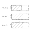
- Figures 1(a), 1(b) and 1(c) are respectively longitudinal cross sectional views of a portion of the piston rings illustrating embodiments of the present invention.
- Figures 1(a) and 1(b) are samples in which a hard film is formed on a wear resistant surface treatment layer of a different type.
- Figure 1(c) is a sample in which a hard film is applied without forming a wear resistant surface treatment layer of a different type.
- Figure 2 is a drawing showing a configuration of the reciprocating friction testing machine.
- Figure 3 is a graph showing test results from the wear tests.
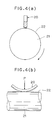
- Figures 4(a) and 4(b) are drawings showing the structure of the pin-on-cylinder friction testing machine.
- Figure 4(a) is a front view partly in cross section.
- Figure 4(b) is a side view.
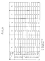
- Figure 5 is a table showing test results from the scuffing tests.
- Figure 6 is an X-ray diffraction pattern of the film of embodiment 4.
- a gas nitrided layer 2 with a thickness of 5 to 15 micrometers is formed on the entire surface of a piston ring 1.
- a hard film 3 with a thickness of 0.5 to 10 micrometers is formed over the gas nitrided layer 2 at the outer circumferential surface.
- the hard film 3 comprises diamond-like carbon in which are dispersed carbides of one or more elements selected from the group consisting of silicon, titanium, tungsten, chromium, molybdenum, niobium, and vanadium.
- the total atomic ratio of one or more elements selected from the group consisting of silicon, titanium, tungsten, chromium, molybdenum, niobium, and vanadium is 5 to 40 percent and the hard film 3 has a Vicker's hardness within a range of 700 to 2000.
- a chromium plating film, or ion plating film 4 such as chromium nitride (CrN, Cr 2 N) film or titanium nitride (TiN) film is formed on the outer circumferential surface of the piston ring 1.
- the hard film 3 is formed in a thickness of 0.5 to 10 micrometers over the film 4.
- the chromium plating film thickness is 5 to 150 micrometers
- the ion plating film thickness is 1 to 150 micrometers.
- Fig. 1(c) shows an example of the hard film 3 directly formed in a thickness of 10 to 30 micrometers on the outer circumferential surface of the piston ring 1 without forming a wear resistant surface treatment layer (gas nitrided layer 2, or chromium plating film or ion plating film 4) which is different in type from the hard film 3.
- a wear resistant surface treatment layer gas nitrided layer 2, or chromium plating film or ion plating film 4
- the film thickness is lower than 10 micrometers, the wear resistance is inadequate and when above 30 micrometers, the adhesion declines and cracks are prone to occur in the film.
- the hard film 3 can be coated by using the reactive ion plating method or reactive sputtering method.
- the hard film 3 is coated onto the substrate by the reactive ion plating method as related below. That is, an inert gas is introduced into a vacuum chamber while the substrate is rotated. After cleaning the substrate surface by ion bombardment, a hydrocarbon gas such as methane which is a source of carbon is introduced into the chamber and while the vicinity of the substrate is maintained in a plasma state, one or more elements selected from the group consisting of silicon, titanium, tungsten, chromium, molybdenum, niobium, and vanadium are vaporized.
- a hydrocarbon gas such as methane which is a source of carbon
- the one or more atoms selected from the group consisting of silicon, titanium, tungsten, chromium, molybdenum, niobium, and vanadium can be deposited as a carbide.
- the ratio of the respective contents of the one or more elements selected from the group consisting of silicon, titanium, tungsten, chromium, molybdenum, niobium, and vanadium can be controled by adjusting the pressure of the reactive gas as well as the evaporation speed of these elements.
- the structures of the hard films of the embodiments 1 through 4 and the comparative examples 6 through 8 were analyzed by X-ray diffraction of each test piece.
- the X-ray tube was a copper tube and a monochromator was used.
- the tube voltage was 40 kilovolts.
- the tube current was 30 milliamperes.
- An X-ray diffraction pattern of the embodiment 4 is shown in Fig. 6.
- Fig. 6 shows the following matters.
- the film of the embodiment 4 has a structure comprised of amorphous carbon and tungsten carbide.
- the hard film in this test was comprised of diamond-like carbon as the main constituent and tungsten carbide or silicon carbide, however the same effect can be obtained with a hard film comprising diamond-like carbon in which are dispersed carbides of one or more elements selected from the group consisting of silicon, titanium, tungsten, chromium, molybdenum, niobium, and vanadium.
Abstract


Description
- The present invention relates to a piston ring for use in internal combustion engines.
- Engines in recent years must meet increased demands for higher output, high revolutions per minute and longer product service life, and must also comply with ever stricter exhaust gas emission regulations. The piston ring must therefore function in a harsher operating environment. Cylinders in such engines are conventionally made out of cast iron and the external circumference of the piston ring has a wear resistant surface treatment layer.
- The wear resistant surface treatment layer on the external circumferential surface of the piston ring of the conventional art is a chromium plating film, nitrided layer, or ion plating film such as chromium nitride (CrN, Cr2N) film or titanium nitride (TiN) film.
- In the initial stage of engine operation, break-in between the cylinder and piston ring is not sufficient so that scuffing may occur between the cylinder and piston ring formed with the above mentioned wear resistant surface treatment layer. Accordingly, a method to improve initial break-in characteristics of these wear resistant surface treatment layers or a wear resistant surface treatment layer having both scuffing resistance and wear resistance is needed.
- To respond the above problem, the following arts have been proposed.
- 1. Japanese Patent Laid-open No. 8-184375 A film of either 98.0 to 99.5 percent molybdenum or chromium or both and the remainder of nitrogen was formed by physical vapor deposition on a nitrided layer or physical vapor deposition film in order to improve the initial break-in characteristics.
- 2. Japanese Patent Publication No. 5-54594 A TiN film was formed over a hard film comprised of CBN, TiC, Ti(C,N), SiC, diamonds or Al2O3 in order to improve the scuffing resistance.On the other hand, the following art involved coating of artificial diamond material has been proposed.
- 3. Japanese Patent Laid-open No. 3-260362 A thin film of artificial diamond material was formed on the piston ring and on the top surface, external circumferential surface and ring groove of the piston in order to improve durability.Further, the following art involved use of a diamond-like carbon film has been proposed.
- 4. Japanese Patent Laid-open No. 5-179451 In order to restrict the adhesion of ferrite structures, a film having amorphous carbon as the main constituent in which tungsten and/or silicon was dispersed was formed on the sliding surface which mates with a sliding surface formed of iron-type material containing ferrite. This technology is utilized for instance, in the hydraulic valve in power steering mechanisms.However, under harsh engine operating conditions, the technology proposed in the above first method has the drawback that the molybdenum or chromium film wears away quickly. The technology proposed in the above second method has a TiN film with excessive hardness so that resistance to scuffing is inadequate. The technology proposed in the above third method has no detailed description of any kind regarding the thin film of artificial diamond material. The technology proposed in the above fourth method describes amorphous carbon in which tungsten or silicon is dispersed, yet provides no description of tungsten carbides or silicon carbides.
-
- It is an object of the present invention to provide a piston ring having both resistance to scuffing and resistance to wear.
- In a piston ring of the present invention formed with a hard film on the outer circumferential surface, the hard film is characterized by comprising diamond-like carbon in which are dispersed carbides of one or more elements selected from the group consisting of silicon, titanium, tungsten, chromium, molybdenum, niobium, and vanadium.
- The diamond-like carbon forming a film of the present invention is configured from any one of the following structures.
- 1. Amorphous carbon structure
- 2. Amorphous carbon structure having partly a diamond structure.
- 3. Amorphous carbon structure having partly a graphite structure.
-
- The hard film of the present invention may be dispersed with non-carbonized metal in minute amounts provided that the effect of the invention is not lost.
- The scuffing resistance of the diamond-like carbon film is inherently high, however a film having both scuffing resistance and wear resistance can be obtained by including carbides of one or more elements selected from the group consisting of silicon, titanium, tungsten, chromium, molybdenum, niobium, and vanadium. This film also has superior initial break-in characteristics.
- The silicon, titanium, tungsten, chromium, molybdenum, niobium, and vanadium content can be measured with an electron probe microanalyzer. The total atomic ratio of the above elements is preferably 5 to 40 percent and preferably the hard film has a Vicker's hardness within a range of 700 to 2000. When the total atomic ratio falls below 5 percent, the hardness, scuffing resistance and wear resistance decline. When the total atomic ratio is above 40 percent, a drop in scuffing resistance and adhesion occurs. When the Vicker's hardness of the hard film is below 700, the wear resistance declines. When the Vicker's hardness is above 2,000, a drop in scuffing resistance and cracks on the film are prone to occur. More preferably, the total atomic ratio is 10 to 30 percent and a Vicker's hardness for the hard film is within a range of 900 to 1200.
- Various embodiments of the present invention will now be described by way of example only, and with reference to the accompanying drawings in which:
- Figures 1(a), 1(b) and 1(c) are respectively longitudinal cross sectional views of a portion of the piston rings illustrating embodiments of the present invention. Figures 1(a) and 1(b) are samples in which a hard film is formed on a wear resistant surface treatment layer of a different type. Figure 1(c) is a sample in which a hard film is applied without forming a wear resistant surface treatment layer of a different type.
- Figure 2 is a drawing showing a configuration of the reciprocating friction testing machine.
- Figure 3 is a graph showing test results from the wear tests.
- Figures 4(a) and 4(b) are drawings showing the structure of the pin-on-cylinder friction testing machine. Figure 4(a) is a front view partly in cross section. Figure 4(b) is a side view.
- Figure 5 is a table showing test results from the scuffing tests.
- Figure 6 is an X-ray diffraction pattern of the film of
embodiment 4. - Hereafter, the preferred embodiments of the present invention will be described while referring to Fig. 1(a) to Fig. 1(c).
- In Fig. 1(a), a gas nitrided
layer 2 with a thickness of 5 to 15 micrometers is formed on the entire surface of apiston ring 1. Ahard film 3 with a thickness of 0.5 to 10 micrometers is formed over the gas nitridedlayer 2 at the outer circumferential surface. Thehard film 3 comprises diamond-like carbon in which are dispersed carbides of one or more elements selected from the group consisting of silicon, titanium, tungsten, chromium, molybdenum, niobium, and vanadium. The total atomic ratio of one or more elements selected from the group consisting of silicon, titanium, tungsten, chromium, molybdenum, niobium, and vanadium is 5 to 40 percent and thehard film 3 has a Vicker's hardness within a range of 700 to 2000. - Another example is shown in Fig. 1(b). A chromium plating film, or
ion plating film 4 such as chromium nitride (CrN, Cr2N) film or titanium nitride (TiN) film is formed on the outer circumferential surface of thepiston ring 1. Thehard film 3 is formed in a thickness of 0.5 to 10 micrometers over thefilm 4. When chromium plating film is used, the chromium plating film thickness is 5 to 150 micrometers, and when ion plating film is used, the ion plating film thickness is 1 to 150 micrometers. - Fig. 1(c) shows an example of the
hard film 3 directly formed in a thickness of 10 to 30 micrometers on the outer circumferential surface of thepiston ring 1 without forming a wear resistant surface treatment layer (gas nitridedlayer 2, or chromium plating film or ion plating film 4) which is different in type from thehard film 3. When the film thickness is lower than 10 micrometers, the wear resistance is inadequate and when above 30 micrometers, the adhesion declines and cracks are prone to occur in the film. - The
hard film 3 can be coated by using the reactive ion plating method or reactive sputtering method. For instance, thehard film 3 is coated onto the substrate by the reactive ion plating method as related below. That is, an inert gas is introduced into a vacuum chamber while the substrate is rotated. After cleaning the substrate surface by ion bombardment, a hydrocarbon gas such as methane which is a source of carbon is introduced into the chamber and while the vicinity of the substrate is maintained in a plasma state, one or more elements selected from the group consisting of silicon, titanium, tungsten, chromium, molybdenum, niobium, and vanadium are vaporized. In such cases, by adjusting the partial pressure of hydrocarbon gas in the reactive gas, the one or more atoms selected from the group consisting of silicon, titanium, tungsten, chromium, molybdenum, niobium, and vanadium can be deposited as a carbide. The ratio of the respective contents of the one or more elements selected from the group consisting of silicon, titanium, tungsten, chromium, molybdenum, niobium, and vanadium can be controled by adjusting the pressure of the reactive gas as well as the evaporation speed of these elements. - Hereafter, the superior scuffing resistance and wear resistance of the piston ring of the present invention will be demonstrated by showing results of wear measurements by means of the reciprocating friction testing machine and results of measurements of scuffing load by means of the pin-on-cylinder friction testing machine.
- 1. Wear test
- (1) Reciprocating friction testing machine
The structure of the reciprocating friction testing
machine used in the test is shown in Fig. 2. A pin shaped
upper test piece 10 is supported by a fixedblock 11 and is pressed against alower test piece 13 by a downward load which is applied by ahydraulic cylinder 12. The flat-shapedlower test piece 13 on the other hand, is supported by amovable block 14 and moved forwards and backwards by acrank mechanism 15. A load cell is denoted by thereference numeral 16. - (2) Test conditions
- Load : 10 kilograms
- Speed : 600 c.p.m.
- Time : 60 minutes
- Lubricating oil : 10W engine oil
- (3) Test piece
- Upper test piece :
- Steel for piston ring Film is formed as shown in Table 1 and Table 2.
- Lower test piece :
- Flake graphite cast iron for cylinder liner 17 X 17 X 70 (mm)
- (4) Hard film forming method The hard film was formed by the reactive ion plating method as related previously. The temperature of the substrate was in a range between 200 to 500°C.
- (5) Test results Test results are shown in Fig. 3. The wear amount of a comparative example 2 is set as 1. The amount of wear of the hard film of the present invention is equivalent to or less than the amount of wear of the TiN and CrN ion plating films of the conventional art known to have excellent resistance to wear. A special feature of the present invention is that the amount of wear of the mating material (cast iron) is small. Further, the hard film comprised of diamond-like carbon demonstrated improved resistance to wear on account of a tungsten carbide or silicon carbide content in specific amounts.
- 2. Scuffing test
- (1) Pin-on-cylinder friction testing machine
The structure of the pin-on-cylinder friction testing
machine used in the scuffing test is shown in Figs. 4(a)
and 4(b). A
test piece 20 as the piston ring is mounted on the upper end of the outercircumferential surface 22 of arotor 21 rotated around the horizontal axis. A load P is applied to thetest piece 20 which is the piston ring, pressing the piston ring against the outer circumferential surface of therotor 21. Therotor 21 is rotated in this state, while supplying lubricating oil to the contact portion between therotor 21 and thetest piece 20 as the piston ring. The test piece was observed for the presence or absence of scuffing on the sliding surface after the testing machine was operated for specified times at different types of loads. - (2) Test conditions
- Rotation speed :
- 1000 r.p.m.
- Load :
- 6 - 16 kilograms
- Time :
- The testing machine was operated for 60 seconds at the specified load and the sliding surface was monitored for the presence or absence of scuffing. The scuffing test was repeated with increasing loads.
- Lubricating oil :
- Dropping of 10W lubricating oil
- (3) Test piece The films shown in Table 1 and Table 2 were formed on the outer circumferential surface of the piston ring.
- (4)
Rotor 21 Flake graphite cast iron for cylinder liner ⊘ 50 mm X 300 mm - (5) Test results
As shown in Fig. 5, the scuffing limit loads of the
hard films of the present invention were demonstrated to be
higher than the scuffing limit loads of the TiN and CrN
films of the conventional art known to have excellent
resistance to wear. Further, the hard film comprised of
diamond-like carbon demonstrated improved scuffing
resistance on account of a tungsten carbide or silicon
carbide content in specific amounts.
No. Under layer Structure of hard film on sliding surface Thickness of hard film on sliding surface µm Vicker's hardness of hard film on sliding surface Embodiment 1 Gas nitrided layer Amorphous carbon and tungsten carbide (W: 14 atomic percent) 5 1300 2 Gas nitrided layer Amorphous carbon and silicon carbide (Si: 30 atomic percent) 5 1800 3 Gas nitrided layer Amorphous carbon and silicon carbide (Si: 7 atomic percent) 5 1000 4 Chromium plating film 100µm Amorphous carbon and tungsten carbide (W: 14 atomic percent) 5 1300 Comparative example 1 None Chromium plating film 60 800 2 None Gas nitrided layer 60 1000 3 Gas nitrided layer CrN ion plating film 30 1600 No. Under layer Structure of hard film on sliding surface Thickness of hard film on sliding surface µm Vicker's hardness of hard film on sliding surface Comparative example 4 Gas nitrided layer TiN ion plating film 10 2000 5 Gas nitrided layer Cr ion plating fim 5 750 6 Gas nitrided layer Amorphous carbon 5 500 7 Gas nitrided layer Amorphous carbon and silicon carbide (Si: 4 atomic percent) 5 650 8 Gas nitrided layer Amorphous carbon and silicon carbide (Si: 42 atomic percent) 5 2100 -
- The structures of the hard films of the
embodiments 1 through 4 and the comparative examples 6 through 8 were analyzed by X-ray diffraction of each test piece. The X-ray tube was a copper tube and a monochromator was used. The tube voltage was 40 kilovolts. The tube current was 30 milliamperes. An X-ray diffraction pattern of theembodiment 4 is shown in Fig. 6. - Fig. 6 shows the following matters.
- 1. A halo is present in 2 = 34° to 42°, which shows that film has amorphous structure.
- 2. The diffraction peak in the vicinity of 2 = 44.5°, 65° and 82° is the diffraction ray from the chromium plating film of the under layer.
- 3. The diffraction peak for the tungsten carbide which can be identified as W2C or W6C2.54 is present in the vicinity of 2 = 34.5° and 38°.
- 4. There is no diffraction peak for metallic tungsten in the vicinity of 2 = 40°, 58° and 73°.
-
- It can be seen from the above items that the film of the
embodiment 4 has a structure comprised of amorphous carbon and tungsten carbide. - The hard film in this test was comprised of diamond-like carbon as the main constituent and tungsten carbide or silicon carbide, however the same effect can be obtained with a hard film comprising diamond-like carbon in which are dispersed carbides of one or more elements selected from the group consisting of silicon, titanium, tungsten, chromium, molybdenum, niobium, and vanadium.
- Although the present invention has been described with reference to the preferred embodiments, it is apparent that the present invention is not limited to the aforesaid preferred embodiments, but various modification can be attained without departing from its scope.
Claims (5)
- A piston ring having a hard film on the outer circumferential surface of said piston ring, wherein said hard film comprises diamond-like carbon in which are dispersed carbides of one or more elements selected from the group consisting of silicon, titanium, tungsten, chromium, molybdenum, niobium, and vanadium.
- A piston ring as claimed in claim 1, wherein content of said one or more elements selected from the group consisting of silicon, titanium, tungsten, chromium, molybdenum, niobium, and vanadium is 5 to 40 atomic percent, and a Vicker's hardness of said hard film is within a range of 700 to 2000.
- A piston ring as claimed in claim 2, wherein said hard film has a thickness of 0.5 to 10 micrometers and said hard film is formed on a wear resistant surface treatment layer of a different type.
- A piston ring as claimed in claim 3, wherein said wear resistant surface treatment layer of a different type is comprised of a chromium plating film, nitrided layer or ion plating film.
- A piston ring as claimed in claim 2, wherein said hard film has a thickness of 10 to 30 micrometers and said hard film is formed directly on the outer circumferential surface of said piston ring.
Applications Claiming Priority (6)
| Application Number | Priority Date | Filing Date | Title |
|---|---|---|---|
| JP282862/97 | 1997-09-30 | ||
| JP28286297 | 1997-09-30 | ||
| JP28286297 | 1997-09-30 | ||
| JP21352698A JP3885375B2 (en) | 1997-09-30 | 1998-07-13 | piston ring |
| JP21352698 | 1998-07-13 | ||
| JP213526/98 | 1998-07-13 |
Publications (3)
| Publication Number | Publication Date |
|---|---|
| EP0905419A2 true EP0905419A2 (en) | 1999-03-31 |
| EP0905419A3 EP0905419A3 (en) | 2000-01-26 |
| EP0905419B1 EP0905419B1 (en) | 2003-11-26 |
Family
ID=26519848
Family Applications (1)
| Application Number | Title | Priority Date | Filing Date |
|---|---|---|---|
| EP98307976A Expired - Lifetime EP0905419B1 (en) | 1997-09-30 | 1998-09-30 | Piston ring |
Country Status (4)
| Country | Link |
|---|---|
| US (1) | US6139022A (en) |
| EP (1) | EP0905419B1 (en) |
| JP (1) | JP3885375B2 (en) |
| DE (1) | DE69819995T2 (en) |
Cited By (12)
| Publication number | Priority date | Publication date | Assignee | Title |
|---|---|---|---|---|
| GB2344150A (en) * | 1998-10-15 | 2000-05-31 | Teikoku Piston Ring Co Ltd | Piston ring with a diamond-like carbon (DLC) film |
| GB2367304A (en) * | 1999-04-07 | 2002-04-03 | Teikoku Piston Ring Co Ltd | Piston ring |
| EP1505322A1 (en) * | 2003-08-08 | 2005-02-09 | Nissan Motor Co., Ltd. | Sliding member and production process thereof |
| WO2005111264A1 (en) * | 2004-05-19 | 2005-11-24 | Center Za Tribologijo In Tehnicno Diagnostiko Fakulteta Za Strojnistvo | Dlc coatings for loaded machine parts, intended for use in boundary-lubrication conditions |
| DE102005063123B3 (en) * | 2005-12-30 | 2007-05-31 | Federal-Mogul Burscheid Gmbh | Piston ring for sealing chamber in cylinder has running-in layer containing hydrogen and nanocrystalline carbide phases |
| US7650976B2 (en) | 2003-08-22 | 2010-01-26 | Nissan Motor Co., Ltd. | Low-friction sliding member in transmission, and transmission oil therefor |
| DE102008062220A1 (en) | 2008-12-13 | 2010-06-17 | Mahle International Gmbh | Sliding layer useful in a sliding element for a tribological system, consists of amorphous carbon and chromium carbide, where particles of the amorphous carbon and chromium carbide are uniformly distributed |
| US8206035B2 (en) | 2003-08-06 | 2012-06-26 | Nissan Motor Co., Ltd. | Low-friction sliding mechanism, low-friction agent composition and method of friction reduction |
| WO2012160138A1 (en) * | 2011-05-25 | 2012-11-29 | Federal-Mogul Burscheid Gmbh | Piston ring with composite coating |
| EP3064810B1 (en) | 2013-10-31 | 2018-04-11 | Kabushiki Kaisha Riken | Piston ring and its production method |
| US10131988B2 (en) | 2009-11-02 | 2018-11-20 | Federal-Mogul Burscheid Gmbh | Sliding element, in particular piston ring, and combination of a sliding element with a mating running element |
| US10458361B2 (en) | 2014-08-27 | 2019-10-29 | Bayerische Motoren Werke Aktiengesellschaft | Coating for metal components, method for coating a metal component, piston for internal combustion engines and motor vehicle |
Families Citing this family (43)
| Publication number | Priority date | Publication date | Assignee | Title |
|---|---|---|---|---|
| JP3555844B2 (en) | 1999-04-09 | 2004-08-18 | 三宅 正二郎 | Sliding member and manufacturing method thereof |
| JP4578716B2 (en) * | 2001-05-08 | 2010-11-10 | 株式会社デンソー | Gasoline lubricated sliding member |
| US7537835B2 (en) * | 2001-09-27 | 2009-05-26 | Kabushiki Kaisha Toyota Chuo Kenkyusho | High friction sliding member |
| JP2003269555A (en) * | 2002-03-19 | 2003-09-25 | Tsubakimoto Chain Co | Wear-resistant tensioner |
| US6969198B2 (en) | 2002-11-06 | 2005-11-29 | Nissan Motor Co., Ltd. | Low-friction sliding mechanism |
| DE602004022732D1 (en) * | 2003-03-26 | 2009-10-08 | Infineum Int Ltd | Use of a composition containing organomolybdenum compound for the lubrication of diamental carbon layers |
| JP4863152B2 (en) | 2003-07-31 | 2012-01-25 | 日産自動車株式会社 | gear |
| US7771821B2 (en) | 2003-08-21 | 2010-08-10 | Nissan Motor Co., Ltd. | Low-friction sliding member and low-friction sliding mechanism using same |
| DE10359802B3 (en) * | 2003-12-19 | 2005-03-31 | Federal-Mogul Burscheid Gmbh | Piston ring for e.g. internal combustion engine, has vapor-deposited layer covering part of running surface, which leaves sharp edges after subsequent removal |
| JP4572688B2 (en) * | 2004-04-27 | 2010-11-04 | 株式会社豊田中央研究所 | Low friction sliding member |
| US7726121B2 (en) * | 2004-08-06 | 2010-06-01 | Yamaha Hatsudoki Kabushiki Kaisha | Engine part |
| US7383807B2 (en) * | 2005-05-23 | 2008-06-10 | Federal-Mogul World Wide, Inc. | Coated power cylinder components for diesel engines |
| CN101208461B (en) * | 2005-05-26 | 2011-07-06 | 萨尔泽曼塔普拉斯有限公司 | Piston ring having hard multi-layer coating |
| JP4901207B2 (en) * | 2005-12-20 | 2012-03-21 | Tpr株式会社 | piston ring |
| US20090020958A1 (en) * | 2006-03-31 | 2009-01-22 | Soul David F | Methods and apparatus for operating an internal combustion engine |
| US7793940B2 (en) * | 2006-05-16 | 2010-09-14 | Skf Usa Inc. | Mechanical end face seal with ultrahard face material |
| JP4954644B2 (en) * | 2006-08-31 | 2012-06-20 | 日本ピストンリング株式会社 | Combination of cylinder liner and piston ring |
| DE102006043303B4 (en) * | 2006-09-14 | 2016-06-16 | Mahle International Gmbh | Sliding element and method for its production |
| DE102006046917C5 (en) * | 2006-10-04 | 2014-03-20 | Federal-Mogul Burscheid Gmbh | Piston ring for internal combustion engines |
| DE102006046915C5 (en) | 2006-10-04 | 2015-09-03 | Federal-Mogul Burscheid Gmbh | Piston ring for internal combustion engines |
| DE102006049756A1 (en) * | 2006-10-21 | 2008-04-24 | Federal-Mogul Burscheid Gmbh | Wear protection layer for piston rings in combustion engines comprises a layer made from layers of different hardness and metallic phases arranged radially over each other |
| DE102007007961C5 (en) * | 2007-02-17 | 2015-08-13 | Federal-Mogul Burscheid Gmbh | piston ring |
| DE102007007962B3 (en) * | 2007-02-17 | 2008-05-08 | Federal-Mogul Burscheid Gmbh | Piston ring has base body with bearing surface, provided with compartmentation, which is provided with wear resistant coating, where partial physical vapor deposition covering layer is applied on bearing surface |
| KR100906858B1 (en) | 2007-08-31 | 2009-07-08 | 현대자동차주식회사 | Piston ring for engine and method for manufacturing the same |
| WO2009069762A1 (en) * | 2007-11-30 | 2009-06-04 | Nippon Piston Ring Co., Ltd. | Steel products for piston rings and piston rings |
| DE102008042896A1 (en) * | 2008-10-16 | 2010-04-22 | Federal-Mogul Burscheid Gmbh | Method for coating a sliding element and sliding element, in particular piston ring or cylinder liner of an internal combustion engine |
| DE102009028504C5 (en) * | 2009-08-13 | 2014-10-30 | Federal-Mogul Burscheid Gmbh | Piston ring with a coating |
| DE102010002687C5 (en) * | 2010-03-09 | 2015-09-10 | Federal-Mogul Burscheid Gmbh | Process for coating at least the inner surface of a piston ring and piston ring |
| DE102010033543A1 (en) * | 2010-08-05 | 2012-02-09 | Bayerische Motoren Werke Aktiengesellschaft | Coating of components made of steel comprises depositing amorphous carbon layer on hydrocarbon containing tungsten layer that is applied directly on the component surface |
| JP6062357B2 (en) * | 2011-02-28 | 2017-01-18 | 日本ピストンリング株式会社 | piston ring |
| JP5865015B2 (en) * | 2011-06-24 | 2016-02-17 | 株式会社リケン | piston ring |
| JP5865014B2 (en) * | 2011-06-24 | 2016-02-17 | 株式会社リケン | piston ring |
| BRPI1103935A2 (en) * | 2011-08-17 | 2013-08-06 | Mahle Metal Leve Sa | piston ring |
| KR20130033580A (en) * | 2011-09-27 | 2013-04-04 | 현대자동차주식회사 | Piston ring for engine and manufacturing method thereof |
| AT511605B1 (en) * | 2011-12-12 | 2013-01-15 | High Tech Coatings Gmbh | CARBON COATING COATING |
| DE102012022906A1 (en) * | 2012-11-23 | 2014-05-28 | Mahle International Gmbh | Piston for internal combustion engine, has piston head, which has circumferential ring section with piston rings, where running surfaces of piston rings are partially provided with coating based on chromium nitride |
| BR102013004749A2 (en) * | 2013-02-27 | 2014-10-07 | Mahle Metal Leve Sa | PISTON RING |
| BR102013011586B1 (en) * | 2013-05-09 | 2022-03-03 | Mahle International Gmbh | Slip and engine block assembly |
| WO2015045745A1 (en) | 2013-09-30 | 2015-04-02 | 株式会社リケン | Piston ring |
| TWM539576U (en) * | 2016-08-29 | 2017-04-11 | Japon Traffic Tech Corp | Nitrogenizing graphite cast iron piston ring |
| RU2671780C1 (en) * | 2017-10-30 | 2018-11-06 | Общество с ограниченной ответственностью "Сборные конструкции инструмента, фрезы Москвитина" | Working part of cutting tool |
| RU2675872C1 (en) * | 2018-02-06 | 2018-12-25 | Общество с ограниченной ответственностью "Сборные конструкции инструмента, фрезы Москвитина" | Cutting tool for handling products made of hard-to-cut materials |
| FR3082527B1 (en) * | 2018-06-18 | 2020-09-18 | Hydromecanique & Frottement | PART COATED WITH A NON-HYDROGEN AMORPHIC CARBON COATING ON AN UNDERLAYMENT CONTAINING CHROME, CARBON AND SILICON |
Citations (4)
| Publication number | Priority date | Publication date | Assignee | Title |
|---|---|---|---|---|
| JPH03260362A (en) | 1990-03-05 | 1991-11-20 | Jerome H Lemelson | Internal-combustion engine and its factors |
| JPH0554594A (en) | 1992-02-05 | 1993-03-05 | Konica Corp | Production of video tape cassette |
| JPH05179451A (en) | 1991-12-27 | 1993-07-20 | Toyota Motor Corp | Combination of sliding member |
| JPH08184375A (en) | 1994-12-29 | 1996-07-16 | Teikoku Piston Ring Co Ltd | Piston ring and manufacture thereof |
Family Cites Families (10)
| Publication number | Priority date | Publication date | Assignee | Title |
|---|---|---|---|---|
| DE2156127B2 (en) * | 1970-12-12 | 1973-05-10 | Nippon Piston Ring K.K., Tokio | PAIR OF SLIDING ELEMENTS LIKE PISTON RING AND CYLINDER WALL |
| JPS5825863B2 (en) * | 1978-11-22 | 1983-05-30 | 日本ピストンリング株式会社 | Piston ring combination |
| US4960643A (en) * | 1987-03-31 | 1990-10-02 | Lemelson Jerome H | Composite synthetic materials |
| DE4115612A1 (en) * | 1991-05-14 | 1992-11-19 | Karl Dr Elbel | Improving edge stability of honing and grinding elements - by physical deposition of coating e.g. oxide(s), nitride(s), carbide(s) and/or boride(s) and/or carbon@ having a diamond structure |
| JP3350157B2 (en) * | 1993-06-07 | 2002-11-25 | 帝国ピストンリング株式会社 | Sliding member and manufacturing method thereof |
| CN1068388C (en) * | 1994-07-30 | 2001-07-11 | 株式会社理研 | Sliding material and method for preparing thereof |
| US5601293A (en) * | 1994-12-22 | 1997-02-11 | Teikoku Piston Ring Co., Ltd. | Sliding member with hard ternery film |
| DE19530511C1 (en) * | 1995-08-18 | 1997-02-20 | Alcan Gmbh | Pistons for internal combustion engines |
| JP3228116B2 (en) * | 1996-01-29 | 2001-11-12 | 帝国ピストンリング株式会社 | Combination oil ring |
| JPH10184914A (en) * | 1996-12-26 | 1998-07-14 | Teikoku Piston Ring Co Ltd | Combination of piston ring and cylinder liner |
-
1998
- 1998-07-13 JP JP21352698A patent/JP3885375B2/en not_active Expired - Lifetime
- 1998-09-28 US US09/161,486 patent/US6139022A/en not_active Expired - Lifetime
- 1998-09-30 DE DE69819995T patent/DE69819995T2/en not_active Expired - Lifetime
- 1998-09-30 EP EP98307976A patent/EP0905419B1/en not_active Expired - Lifetime
Patent Citations (4)
| Publication number | Priority date | Publication date | Assignee | Title |
|---|---|---|---|---|
| JPH03260362A (en) | 1990-03-05 | 1991-11-20 | Jerome H Lemelson | Internal-combustion engine and its factors |
| JPH05179451A (en) | 1991-12-27 | 1993-07-20 | Toyota Motor Corp | Combination of sliding member |
| JPH0554594A (en) | 1992-02-05 | 1993-03-05 | Konica Corp | Production of video tape cassette |
| JPH08184375A (en) | 1994-12-29 | 1996-07-16 | Teikoku Piston Ring Co Ltd | Piston ring and manufacture thereof |
Cited By (22)
| Publication number | Priority date | Publication date | Assignee | Title |
|---|---|---|---|---|
| US6325385B1 (en) | 1998-10-15 | 2001-12-04 | Teikoku Piston Ring Co., Ltd. | Piston ring |
| GB2344150B (en) * | 1998-10-15 | 2002-10-09 | Teikoku Piston Ring Co Ltd | Piston ring |
| GB2344150A (en) * | 1998-10-15 | 2000-05-31 | Teikoku Piston Ring Co Ltd | Piston ring with a diamond-like carbon (DLC) film |
| GB2367304A (en) * | 1999-04-07 | 2002-04-03 | Teikoku Piston Ring Co Ltd | Piston ring |
| US6508473B1 (en) | 1999-04-07 | 2003-01-21 | Teikoku Piston Ring Co., Ltd. | Piston ring |
| GB2367304B (en) * | 1999-04-07 | 2004-05-26 | Teikoku Piston Ring Co Ltd | Piston ring |
| US8206035B2 (en) | 2003-08-06 | 2012-06-26 | Nissan Motor Co., Ltd. | Low-friction sliding mechanism, low-friction agent composition and method of friction reduction |
| US8575076B2 (en) | 2003-08-08 | 2013-11-05 | Nissan Motor Co., Ltd. | Sliding member and production process thereof |
| EP1990564A1 (en) | 2003-08-08 | 2008-11-12 | Nissan Motor Co., Ltd. | Sliding member and production process thereof |
| EP1505322A1 (en) * | 2003-08-08 | 2005-02-09 | Nissan Motor Co., Ltd. | Sliding member and production process thereof |
| US7650976B2 (en) | 2003-08-22 | 2010-01-26 | Nissan Motor Co., Ltd. | Low-friction sliding member in transmission, and transmission oil therefor |
| WO2005111264A1 (en) * | 2004-05-19 | 2005-11-24 | Center Za Tribologijo In Tehnicno Diagnostiko Fakulteta Za Strojnistvo | Dlc coatings for loaded machine parts, intended for use in boundary-lubrication conditions |
| US8201831B2 (en) | 2005-12-30 | 2012-06-19 | Federal-Mogul Burscheid Gmbh | Sliding element, in particular piston ring, method for manufacturing a sliding element, sliding system and coating for a sliding element |
| DE102005063123B3 (en) * | 2005-12-30 | 2007-05-31 | Federal-Mogul Burscheid Gmbh | Piston ring for sealing chamber in cylinder has running-in layer containing hydrogen and nanocrystalline carbide phases |
| EP1966524B2 (en) † | 2005-12-30 | 2014-10-08 | Federal-Mogul Burscheid GmbH | Sliding element, in particular piston ring, method for manufacturing a sliding element, sliding system and coating for a sliding element |
| DE102008062220A1 (en) | 2008-12-13 | 2010-06-17 | Mahle International Gmbh | Sliding layer useful in a sliding element for a tribological system, consists of amorphous carbon and chromium carbide, where particles of the amorphous carbon and chromium carbide are uniformly distributed |
| US10131988B2 (en) | 2009-11-02 | 2018-11-20 | Federal-Mogul Burscheid Gmbh | Sliding element, in particular piston ring, and combination of a sliding element with a mating running element |
| WO2012160138A1 (en) * | 2011-05-25 | 2012-11-29 | Federal-Mogul Burscheid Gmbh | Piston ring with composite coating |
| RU2579537C2 (en) * | 2011-05-25 | 2016-04-10 | Федераль-Могуль Буршейд Гмбх | Piston ring having combined coating |
| EP3064810B1 (en) | 2013-10-31 | 2018-04-11 | Kabushiki Kaisha Riken | Piston ring and its production method |
| EP3064810B2 (en) † | 2013-10-31 | 2021-03-31 | Kabushiki Kaisha Riken | Piston ring and its production method |
| US10458361B2 (en) | 2014-08-27 | 2019-10-29 | Bayerische Motoren Werke Aktiengesellschaft | Coating for metal components, method for coating a metal component, piston for internal combustion engines and motor vehicle |
Also Published As
| Publication number | Publication date |
|---|---|
| US6139022A (en) | 2000-10-31 |
| JPH11172413A (en) | 1999-06-29 |
| EP0905419B1 (en) | 2003-11-26 |
| DE69819995D1 (en) | 2004-01-08 |
| JP3885375B2 (en) | 2007-02-21 |
| DE69819995T2 (en) | 2004-04-15 |
| EP0905419A3 (en) | 2000-01-26 |
Similar Documents
| Publication | Publication Date | Title |
|---|---|---|
| EP0905419B1 (en) | Piston ring | |
| EP0905420B1 (en) | Piston ring | |
| US6325385B1 (en) | Piston ring | |
| US6279913B1 (en) | Sliding member and manufacturing method thereof | |
| US5618590A (en) | Process for manufacturing a piston ring | |
| EP1876345B1 (en) | Piston ring for internal combustion engines | |
| Su et al. | Comparison of tribological behavior of three films—TiN, TiCN and CrN—grown by physical vapor deposition | |
| US11293548B2 (en) | Sliding member and coating film | |
| GB2296257A (en) | Sliding member having surface of molybdenum nitride and chromium nitride | |
| US6149162A (en) | Sliding member | |
| EP1375695A1 (en) | Wear-resistant sliding member | |
| JP2003113941A (en) | Piston ring and combination structure of piston ring and ring groove of piston | |
| JP4067678B2 (en) | Combination oil ring spacer expander and combination oil ring | |
| JP2001280497A (en) | Combination of cylinder made of aluminum alloy and piston ring | |
| JP4374153B2 (en) | piston ring | |
| JP3266439B2 (en) | Piston ring and method of manufacturing the same | |
| JP2003042294A (en) | Piston ring | |
| JP4374154B2 (en) | piston ring | |
| JP3388047B2 (en) | Piston ring and method of manufacturing the same | |
| CN111148858B (en) | Sliding member | |
| JP4393391B2 (en) | Sliding member | |
| JP2003042293A (en) | Piston ring | |
| JP3286097B2 (en) | Sliding member and manufacturing method thereof | |
| JP2534566Y2 (en) | piston ring | |
| JP2020193656A (en) | Combination of sliding member and lubricant |
Legal Events
| Date | Code | Title | Description |
|---|---|---|---|
| PUAI | Public reference made under article 153(3) epc to a published international application that has entered the european phase |
Free format text: ORIGINAL CODE: 0009012 |
|
| AK | Designated contracting states |
Kind code of ref document: A2 Designated state(s): DE GB |
|
| AX | Request for extension of the european patent |
Free format text: AL;LT;LV;MK;RO;SI |
|
| PUAL | Search report despatched |
Free format text: ORIGINAL CODE: 0009013 |
|
| AK | Designated contracting states |
Kind code of ref document: A3 Designated state(s): AT BE CH CY DE DK ES FI FR GB GR IE IT LI LU MC NL PT SE |
|
| AX | Request for extension of the european patent |
Free format text: AL;LT;LV;MK;RO;SI |
|
| 17P | Request for examination filed |
Effective date: 20000221 |
|
| AKX | Designation fees paid |
Free format text: DE GB |
|
| GRAH | Despatch of communication of intention to grant a patent |
Free format text: ORIGINAL CODE: EPIDOS IGRA |
|
| GRAS | Grant fee paid |
Free format text: ORIGINAL CODE: EPIDOSNIGR3 |
|
| GRAA | (expected) grant |
Free format text: ORIGINAL CODE: 0009210 |
|
| STAA | Information on the status of an ep patent application or granted ep patent |
Free format text: STATUS: THE PATENT HAS BEEN GRANTED |
|
| AK | Designated contracting states |
Kind code of ref document: B1 Designated state(s): DE GB |
|
| REG | Reference to a national code |
Ref country code: GB Ref legal event code: FG4D |
|
| REF | Corresponds to: |
Ref document number: 69819995 Country of ref document: DE Date of ref document: 20040108 Kind code of ref document: P |
|
| PLBE | No opposition filed within time limit |
Free format text: ORIGINAL CODE: 0009261 |
|
| 26N | No opposition filed |
Effective date: 20040827 |
|
| PGFP | Annual fee paid to national office [announced via postgrant information from national office to epo] |
Ref country code: GB Payment date: 20120912 Year of fee payment: 15 |
|
| GBPC | Gb: european patent ceased through non-payment of renewal fee |
Effective date: 20130930 |
|
| PG25 | Lapsed in a contracting state [announced via postgrant information from national office to epo] |
Ref country code: GB Free format text: LAPSE BECAUSE OF NON-PAYMENT OF DUE FEES Effective date: 20130930 |
|
| REG | Reference to a national code |
Ref country code: DE Ref legal event code: R082 Ref document number: 69819995 Country of ref document: DE Representative=s name: KUDLEK & GRUNERT PATENTANWAELTE PARTNERSCHAFT, DE |
|
| REG | Reference to a national code |
Ref country code: DE Ref legal event code: R082 Ref document number: 69819995 Country of ref document: DE Representative=s name: KUDLEK & GRUNERT PATENTANWAELTE PARTNERSCHAFT, DE Effective date: 20150320 Ref country code: DE Ref legal event code: R081 Ref document number: 69819995 Country of ref document: DE Owner name: TPR CO., LTD., JP Free format text: FORMER OWNER: TEIKOKU PISTON RING CO., LTD., TOKYO, JP Effective date: 20150320 |
|
| PGFP | Annual fee paid to national office [announced via postgrant information from national office to epo] |
Ref country code: DE Payment date: 20170928 Year of fee payment: 20 |
|
| REG | Reference to a national code |
Ref country code: DE Ref legal event code: R071 Ref document number: 69819995 Country of ref document: DE |