EP0906994B1 - Panel, especially for floor coverings - Google Patents
Panel, especially for floor coverings Download PDFInfo
- Publication number
- EP0906994B1 EP0906994B1 EP97117212A EP97117212A EP0906994B1 EP 0906994 B1 EP0906994 B1 EP 0906994B1 EP 97117212 A EP97117212 A EP 97117212A EP 97117212 A EP97117212 A EP 97117212A EP 0906994 B1 EP0906994 B1 EP 0906994B1
- Authority
- EP
- European Patent Office
- Prior art keywords
- panels
- groove
- tongue
- panel
- grooves
- Prior art date
- Legal status (The legal status is an assumption and is not a legal conclusion. Google has not performed a legal analysis and makes no representation as to the accuracy of the status listed.)
- Expired - Lifetime
Links
Images

Classifications
-
- E—FIXED CONSTRUCTIONS
- E04—BUILDING
- E04F—FINISHING WORK ON BUILDINGS, e.g. STAIRS, FLOORS
- E04F15/00—Flooring
- E04F15/02—Flooring or floor layers composed of a number of similar elements
- E04F15/04—Flooring or floor layers composed of a number of similar elements only of wood or with a top layer of wood, e.g. with wooden or metal connecting members
-
- E—FIXED CONSTRUCTIONS
- E04—BUILDING
- E04F—FINISHING WORK ON BUILDINGS, e.g. STAIRS, FLOORS
- E04F2201/00—Joining sheets or plates or panels
- E04F2201/01—Joining sheets, plates or panels with edges in abutting relationship
- E04F2201/0107—Joining sheets, plates or panels with edges in abutting relationship by moving the sheets, plates or panels substantially in their own plane, perpendicular to the abutting edges
-
- E—FIXED CONSTRUCTIONS
- E04—BUILDING
- E04F—FINISHING WORK ON BUILDINGS, e.g. STAIRS, FLOORS
- E04F2201/00—Joining sheets or plates or panels
- E04F2201/02—Non-undercut connections, e.g. tongue and groove connections
- E04F2201/025—Non-undercut connections, e.g. tongue and groove connections with tongue and grooves alternating transversally in the direction of the thickness of the panel, e.g. multiple tongue and grooves oriented parallel to each other
Definitions
- the invention relates to a panel intended in particular for floor coverings has a load-bearing plate made of wood-based material, at least on one surface is provided with a coating, the plate at its edges Has grooves and tongues, which in or on corresponding grooves and tongues further same panels fit.
- the top of the springs individual panels of glue are applied before the springs in the corresponding grooves of the Counter panels are inserted.
- the glue applied to the feathers is used in the Inserting into a groove of a counter panel displaces and not only gives way to the deeper than the height of the tongue formed groove, but also reaches the top of the assembled panels, so that gluing not only in the contact area between the surface of the tongue and the opposite wall of the groove, but also takes place at the joints between the assembled panels.
- To the Glue spilled from the top of the assembled panels is removed by wiping removed from the surface.
- the invention has for its object the connection between tongue and groove having panels to be laid side by side and in particular To improve floor panels in such a way that even if there are minor bumps in the Are present or arise after laying the floor covering, no damage can occur in the area of the joints of the panels that affect the Duration would result in the floor covering having to be replaced completely.
- the invention provides a double tongue and groove connection for panels and
- floor panels are created which are compared to conventional gluable tongue and groove connections enlarged contact areas at the connection points and thus allows larger gluing areas. This results in a better hold or one improved stability between the mated and glued together Panels if they are laid on a surface that is not quite level. Let too largely avoid misplacement by the invention.
- Each panel 1 has one made of wood like HDF (High Density Fiber), MDF (Medium Density Fiber) or Span-Holzstoff existing load-bearing plate 2, which on the Top side with a surface, for example made of printed paper existing top layer 3 is provided. Over this top layer 3 is one Wear-resistant, transparent cover layer 4 is arranged.
- HDF High Density Fiber
- MDF Medium Density Fiber
- Span-Holzstoff existing load-bearing plate 2 which on the Top side with a surface, for example made of printed paper existing top layer 3 is provided.
- Wear-resistant, transparent cover layer 4 is arranged.
- each load-bearing plate 2 with a stabilizing one provided another cover layer 5, which is also arranged under a cover layer 6, which, however, need not be transparent, because the cover layer 5 is not like that Cover layer 3, forms a surface decor.
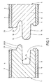
- Each panel has a continuous and itself on a longitudinal edge and a front edge slightly tapered deep groove 7 on the inside and an outwardly protruding wedge-shaped nose 8, which serves as a kind of spring.
- each panel 1 is one in the deep groove 7 of the same panel provided conical tongue 9 above the there is a wedge-shaped groove 10 into which the wedge-shaped nose 8 is the same Panels 1 fits.
- Fig. 2 shows how the conical tongue 9 in a groove 7 and the wedge-shaped Nose 8 fit into a wedge-shaped groove 10 belonging to panels 1.
- Each nose 8 is shorter than the depth of the associated groove 10 and each tongue 9 is shorter formed as the depth of the associated groove 7, so that in each groove 7 and 10 a free Room 11 or 12 remains when two panels 1, as shown in FIG. 2, are nested are.
- each spring 9 glue When laying a covering such as a floor covering with panels 1 in the Drawing shown type is applied to the top 13 of each spring 9 glue. In addition, however, this is not necessary in every case, on the underside 14 of the Spring 9 additional glue can be applied.
Abstract
Description
Die Erfindung betrifft ein insbesondere für Fußbodenbeläge bestimmtes Paneel, das eine aus Holzwerkstoff bestehende tragende Platte aufweist, die zumindest auf einer Oberfläche mit einer Beschichtung versehen ist, wobei die Platte an ihren Kanten bzw. Rändern Nuten und Federn aufweist, die in bzw. auf entsprechende Nuten und Federn weiterer gleicher Paneele passen.The invention relates to a panel intended in particular for floor coverings has a load-bearing plate made of wood-based material, at least on one surface is provided with a coating, the plate at its edges Has grooves and tongues, which in or on corresponding grooves and tongues further same panels fit.
Bei der Verlegung derartiger Paneele zu Fußböden wird auf die Oberseite der Federn der einzelnen Paneele Leim aufgetragen, bevor die Federn in die entsprechenden Nuten der Gegenpaneele eingesteckt werden. Der auf die Federn aufgetragene Leim wird beim Einstecken in eine Nut eines Gegenpaneels verdrängt und weicht nicht nur in die tiefer als die Höhe der Feder ausgebildete Nut aus, sondern gelangt auch zur Oberseite der zusammengesteckten Paneele, so daß eine Verleimung nicht nur im Kontaktbereich zwischen der Oberfläche der Feder und der gegenüberliegenden Wand der Nut, sondern auch an den Stoßstellen zwischen den zusammengesteckten Paneelen stattfindet. An die Oberseite der zusammengesteckten Paneele ausgetretener Leim wird durch Abwischen von der Oberfläche entfernt.When laying such panels on floors, the top of the springs individual panels of glue are applied before the springs in the corresponding grooves of the Counter panels are inserted. The glue applied to the feathers is used in the Inserting into a groove of a counter panel displaces and not only gives way to the deeper than the height of the tongue formed groove, but also reaches the top of the assembled panels, so that gluing not only in the contact area between the surface of the tongue and the opposite wall of the groove, but also takes place at the joints between the assembled panels. To the Glue spilled from the top of the assembled panels is removed by wiping removed from the surface.
Da wegen schwankender Fertigungstoleranzen der ineinanderzusteckenden Federn und Nuten sowie der zusammenzusteckenden Paneele Auskehlungen im Bereich zwischen dem Übergang der Federn zu den Stirnseiten bzw. Rändern der Paneele sowie eine größere Tiefe der Nuten als die vorstehende Höhe der einzusteckenden Federn notwendig sind, ist der für eine Klebeverbindung zwischen den Federn und Nuten und den aneinanderstoßenden Stirnenden bzw. Rändern der zusammenzusteckenden und miteinander zu verbindenden Paneele vorhandene Bereich verhältnismäßig gering.Because of fluctuating manufacturing tolerances of the nested springs and Grooves and the panels to be plugged in grooves in the area between the Transition of the springs to the end faces or edges of the panels as well as a larger one Depth of the grooves than the protruding height of the springs to be inserted is necessary the one for an adhesive connection between the tongues and grooves and the butting ends or edges of the to be plugged together and panels to be connected to one another are relatively small.
Wegen dieser Problematik kommt es häufig zu Fehlern oder Schwachstellen bei der Verlegung von Fußböden mit aus derartigen Paneelen zusammengesetzten Belägen, die dazu führen, daß die Klebzonen zwischen Paneelen zumindest teilweise reißen und damit im Belag Risse oder sonstige Öffnungen entstehen, durch die Luftfeuchtigkeit und insbesondere für Reinigungszwecke verwendetes Wasser eindringen kann. Ist einmal Feuchtigkeit in eine Stoß- und Klebstelle zwischen aneinanderstoßenden Paneelen eingedrungem, beginnt das Material der aus Holzwerkstoff bestehenden Paneele zu arbeiten, was schließlich zu einem Werfen des verlegten Fußbodenbelages führt. Ein derart schadhaft gewordener Fußboden ist nicht mehr zu reparieren. Vielmehr muß er vollständig ausgewechselt werden.Because of this problem, errors or weak points often occur in the Laying of floors with coverings composed of such panels, the cause the adhesive zones between panels to at least partially tear and thus Cracks or other openings appear in the covering due to the air humidity and water used in particular for cleaning purposes can penetrate. Once upon a time Moisture in an abutting and gluing point between abutting panels penetrated, the material of the panels made of wood-based material begins to close work, which ultimately leads to a throw of the installed floor covering. On Floor that has become damaged can no longer be repaired. Rather, he has to be replaced completely.
Solche Schäden an aus über Nut- und Federverbindungen verlegten Paneelen bestehenden Fußböden entstehen nicht nur bei unsachgerechter Verlegung, sondern auch dann, wenn die Paneele sorgfältig auf einem sorgfältig vorbereiteten Untergrund fachgerecht verlegt werden und auch nur kleinste Unebenheiten auf dem Untergrund vorhanden sind und nach dem Verlegen des Fußbodenbelages Veränderungen des Untergrundes Unebenheiten des Untergrundes entstehen, beispielsweise durch Setzungen im Gebäude, in welchem der Fußboden verlegt ist.Such damage to panels consisting of tongue and groove connections Floors are created not only when improperly installed, but also when the panels are carefully laid on a carefully prepared surface and there are even the smallest bumps on the surface and after laying the floor covering, changes in the surface unevenness of the subsoil, for example due to subsidence in the building in which the Floor is laid.
Der Erfindung liegt die Aufgabe zugrunde, die Verbindung zwischen Nut und Feder aufweisenden, nebeneinander zu verlegenden Paneelen und insbesondere Fußbodenpaneelen derart zu verbessern, daß auch dann, wenn kleinere Unebenheiten im Untergrund vorhanden sind oder sich nach dem Verlegen des Fußbodenbelages ergeben, sich keine Schäden im Bereich der Stoßstellen der Paneele einstellen können, die auf die Dauer dazu führen würden, daß der Fußbodenbelag ganz ausgewechselt werden muß.The invention has for its object the connection between tongue and groove having panels to be laid side by side and in particular To improve floor panels in such a way that even if there are minor bumps in the Are present or arise after laying the floor covering, no damage can occur in the area of the joints of the panels that affect the Duration would result in the floor covering having to be replaced completely.
Diese Aufgabe wird erfindungsgemäß mit einem Paneel gelöst, welches die Merkmale des
Patentanspruches 1 aufweist. Vorteilhafte Ausgestaltungen der Erfindung sind Gegenstand
der Unteransprüche.This object is achieved according to the invention with a panel which has the features of
Durch die Erfindung wird eine doppelte Nut-Feder-Verbindung für Paneele und insbesondere Fußbodenpaneele geschaffen, die gegenüber üblichen verleimbaren Nut-Feder-Verbindungen vergrößerte Kontaktflächen an den Verbindungsstellen und damit größere Verleimungsbereiche ermöglicht. Dadurch ergibt sich ein besserer Halt bzw. eine verbesserte Stabilität zwischen den zusammengesteckten und miteinander verleimten Paneelen, wenn diese auf einem nicht ganz ebenen Untergrund verlegt sind. Auch lassen sich durch die Erfindung Verlegungsfehler weitgehend vermeiden.The invention provides a double tongue and groove connection for panels and In particular, floor panels are created which are compared to conventional gluable tongue and groove connections enlarged contact areas at the connection points and thus allows larger gluing areas. This results in a better hold or one improved stability between the mated and glued together Panels if they are laid on a surface that is not quite level. Let too largely avoid misplacement by the invention.
In der Zeichnung ist ein Ausführungsbeispiel von erfindungsgemäß ausgebildeten Paneelen schematisch dargestellt, und zwar zeigt
- Fig. 1
- einen Querschnitt von zwei benachbarten durch Zusammenstecken miteinander zu verbindenden erfindungsgemäß ausgebildeten Paneelen vor dem Zusammenstecken und
- Fig. 2
- einen Querschnitt der zusammengesteckten Paneele aus Fig. 1, wobei die Verleimungsbereiche angezeigt und somit zu erkennen sind.
- Fig. 1
- a cross section of two adjacent panels according to the invention to be connected by plugging together before plugging together and
- Fig. 2
- a cross section of the assembled panels of Fig. 1, wherein the gluing areas are displayed and thus can be seen.
Jedes Paneel 1 weist eine aus Holzstoff wie HDF (High Density Fibre) , MDF (Medium
Density Fibre) oder Span-Holzstoff bestehende tragende Platte 2 auf, welche an der
Oberseite mit einer als Oberfläche dienenden, beispielsweise aus bedrucktem Papier
bestehenden Deckschicht 3 versehen ist. Über dieser Deckschicht 3 ist eine
verschleißfeste, durchsichtige Abdeckschicht 4 angeordnet.Each
An der Unterseite ist jede tragende Platte 2 mit einer der Stabilisierung dienenden
weiteren Deckschicht 5 versehen, die ebenfalls unter einer Abdeckschicht 6 angeordnet ist,
welche jedoch nicht durchsichtig sein muß, weil die Deckschicht 5 nicht wie die
Deckschicht 3, ein Oberflächendekor bildet.At the bottom is each load-bearing
Jedes Paneel weist an einer Längskante und einer Stirnkante eine durchgehende und sich
nach innen leicht konisch verjüngende tiefe Nut 7 sowie eine nach außen vorstehende,
keilförmige Nase 8 auf, die als eine Art Feder dient.Each panel has a continuous and itself on a longitudinal edge and a front edge
slightly tapered
An der zweiten Längskante und der zweiten Stirnkante ist jedes Paneel 1 mit einer in die
tiefe Nut 7 eines gleichen Paneels passenden konischen Feder 9 versehen, oberhalb der
sich eine keilförmige Nut 10 befindet, in welche die keilförmige Nase 8 eines gleichen
Paneels 1 paßt. Fig. 2 zeigt, wie die konische Feder 9 in eine Nut 7 und die keilförmige
Nase 8 in eine keilförmige Nut 10 zusammengehörenden Paneele 1 passen.At the second longitudinal edge and the second end edge, each
Jede Nase 8 ist kürzer als die Tiefe der zugehörigen Nut 10 und jede Feder 9 ist kürzer
als die Tiefe der zugehörigen Nut 7 ausgebildet, so daß in jeder Nut 7 und 10 ein freier
Raum 11 bzw. 12 verbleibt, wenn zwei Paneele 1, wie Fig. 2 zeigt, ineinandergesteckt
sind. Each
Beim Verlegen eines Belages wie eines Fußbodenbelages mit Paneelen 1 der in der
Zeichnung gezeigten Art wird auf die Oberseite 13 jeder Feder 9 Leim aufgetragen.
Zusätzlich kann, jedoch ist dies nicht in jedem Falle notwendig, auf die Unterseite 14 der
Feder 9 weiterer Leim aufgetragen werden.When laying a covering such as a floor covering with
Werden nun zwei Paneele 1 aus der in Fig. 1 gezeigten Position in die in Fig. 2 gezeigte
Position zusammengesteckt, so gelangt die Oberseite 13 jeder Feder 9 mit der oben
liegenden Innenseite 15 jeder Nut 7 in Kontakt, ebenso wie die Unterseite 14 der Feder 9
mit der unten liegenden Innenseite 16 der keilförmig oder konisch ausgebildeten Nut 7 in
Kontakt kommt, wie Fig. 2 zeigt. Die Kontaktbereiche 17 und 18 sind in Fig. 2
zu erkennen.Two
Beim Zusammenstecken zweier Paneele 1 wird auf der Oberseite 13 und gegebenenfalls
der Unterseite 14 jeder konischen Feder 9 befindlicher Leim abgestrichen und gleichmäßig
über die Kontaktbereiche 17 und 18 verteilt. Überschüssiger Leim kann in die freien
Räume 11 und 12 sowie einen an der Unterseite benachbarter Paneele befindlichen
weiteren freien Raum 19 ausweichen. In den freien Raum 12 gelangender überschüssiger
Leim wird beim Zusammenstecken von zwei Paneelen auf die Oberseite 20 jeder
keilförmigen Nase 8 und die Innenseite 21 jeder keilförmigen Nut 10 verdrängt, so daß
eine zusätzliche Verleimung im Kontaktbereich 22 zwischen der Oberseite der
keilförmigen Nase 8 und der keilförmigen Nut 10 entsteht.When two
Schließlich gelangen zusammengesteckte Paneele 1 auch im Bereich ihrer oberhalb der
Nasen 8 und Nuten 10 befindlichen senkrechten Stirnseiten 23 in Kontakt miteinander, so
daß auch hier in einem Kontaktbereich 24 eine Verleimung stattfindet. Überschüssiger
Leim, der aus dem Kontaktbereich 24 auf die Oberfläche der zusammengesteckten Paneele
1 austritt, wird nach dem Zusammenstecken der Paneele vom Verleger abgewischt, bevor
er aushärtet. Finally, assembled
An der Unterseite der zusammengesteckten Paneele 1 verbleibt ein offener Spalt 25, in
und durch den gegebenenfalls weiterer überschüssiger Leim entweichen kann. Hier ist ein
Kontakt zwischen den zusammengesteckten Paneelen 1 nicht notwendig.On the underside of the assembled
Wegen der in der Zeichnung gezeigten und vorstehend beschriebenen speziellen doppelten
Nut-Feder-Verbindung der zusammengesteckten Paneele 1 ist die mit Hilfe von Leim
erzielte feste Verbindung zwischen den Paneelen stabiler als bei einfachen Nut-Feder-Verbindungen,
so daß ein aus den Paneelen 1 verlegter Fußbodenbelag auch dann die
notwendige Stabilität aufweist, wenn der Untergrund nicht absolut eben ist.
Dementsprechend besteht auch nicht die Gefahr, daß aus den Paneelen 1 verlegte
Fußbodenbeläge im Bereich von Verbindungsstellen reißen können und in dadurch
entstehende Risse Feuchtigkeit eindringen kann, was zu einem Werfen bzw. Aufwerfen
des Fußbodenbelages und damit zu einer Zerstörung des gesamten Fußbodens führen
kann.Because of the special double shown in the drawing and described above
The tongue and groove connection of the assembled
Claims (4)
- Panel, especially for floor coverings, with a carrier board (2) made from wooden material, which is provided at least on one surface with a coating (3,4; 5,6), wherein the edges of the board are provided with grooves and tongues, which fit into and/or onto corresponding grooves and tongues of other identical panels, characterised in that the board is provided at each outer edge both with a groove (7 and 10 respectively) and also with a tongue (9 and 8 respectively), which are arranged above one another.
- Panel according to claim 1, characterised in that the groove (7) and/and tongue (9) disposed in each case in the lower position, is designed to be larger than the tongue (8) and/or groove (10) arranged in the higher position.
- Panel according to claim 1 or 2, characterised in that the grooves (7; 10) and tongues (9; 8) are designed with a conical cross-section.
- Panel according to any one of claims 1 to 3, characterised in that each groove (10) and tongue (8) disposed in the higher position is designed in a wedge shape.
Priority Applications (8)
| Application Number | Priority Date | Filing Date | Title |
|---|---|---|---|
| ES97117212T ES2196228T5 (en) | 1997-10-04 | 1997-10-04 | PANEL, IN PARTICULAR, FOR SOIL COATING. |
| DE29724334U DE29724334U1 (en) | 1997-10-04 | 1997-10-04 | Panel, in particular for floor coverings |
| AT97117212T ATE237052T1 (en) | 1997-10-04 | 1997-10-04 | PANEL, ESPECIALLY FOR FLOORING |
| DK97117212T DK0906994T4 (en) | 1997-10-04 | 1997-10-04 | Panel, especially for flooring |
| DE59709794T DE59709794D1 (en) | 1997-10-04 | 1997-10-04 | Panel, in particular for floor coverings |
| PT97117212T PT906994E (en) | 1997-10-04 | 1997-10-04 | PANEL, IN SPECIAL FOR CHAO COATING |
| DE29803708U DE29803708U1 (en) | 1997-10-04 | 1998-03-04 | Panel, in particular for floor coverings |
| US09/262,479 US6247285B1 (en) | 1997-10-04 | 1999-03-04 | Flooring panel |
Applications Claiming Priority (1)
| Application Number | Priority Date | Filing Date | Title |
|---|---|---|---|
| DE29803708U DE29803708U1 (en) | 1997-10-04 | 1998-03-04 | Panel, in particular for floor coverings |
Publications (3)
| Publication Number | Publication Date |
|---|---|
| EP0906994A1 EP0906994A1 (en) | 1999-04-07 |
| EP0906994B1 true EP0906994B1 (en) | 2003-04-09 |
| EP0906994B2 EP0906994B2 (en) | 2007-10-24 |
Family
ID=26061269
Family Applications (1)
| Application Number | Title | Priority Date | Filing Date |
|---|---|---|---|
| EP97117212A Expired - Lifetime EP0906994B2 (en) | 1997-10-04 | 1997-10-04 | Panel, especially for floor coverings |
Country Status (6)
| Country | Link |
|---|---|
| EP (1) | EP0906994B2 (en) |
| AT (1) | ATE237052T1 (en) |
| DE (2) | DE59709794D1 (en) |
| DK (1) | DK0906994T4 (en) |
| ES (1) | ES2196228T5 (en) |
| PT (1) | PT906994E (en) |
Cited By (2)
| Publication number | Priority date | Publication date | Assignee | Title |
|---|---|---|---|---|
| US6647689B2 (en) | 2002-02-18 | 2003-11-18 | E.F.P. Floor Products Gmbh | Panel, particularly a flooring panel |
| US7603826B1 (en) | 2000-05-16 | 2009-10-20 | Kronospan Technical Company Ltd | Panels with coupling means |
Families Citing this family (18)
| Publication number | Priority date | Publication date | Assignee | Title |
|---|---|---|---|---|
| SE514645C2 (en) | 1998-10-06 | 2001-03-26 | Perstorp Flooring Ab | Floor covering material comprising disc-shaped floor elements intended to be joined by separate joint profiles |
| DE29914604U1 (en) * | 1999-08-20 | 2001-01-04 | Kronotex Gmbh Holz Und Kunstha | Panel, especially floor panel |
| DE19945279C1 (en) * | 1999-09-22 | 2001-04-05 | Kronospan Tech Co Ltd | Device and method for producing floor panels and panels manufactured in accordance with the method |
| WO2001021365A1 (en) | 1999-09-22 | 2001-03-29 | Kronospan Technical Company Ltd. | Device and method for producing floor panels |
| EP1157176B1 (en) | 1999-12-27 | 2003-10-22 | Kronospan Technical Company Ltd. | Panels with coupling means |
| CN1187507C (en) | 2000-03-07 | 2005-02-02 | E·F·P·地板制品有限公司 | Mechanical connection of panels |
| CZ294391B6 (en) * | 2000-03-07 | 2004-12-15 | E. F. P. Floor Products Fussböden Gmbh | Mechanical connection of panels |
| SE518184C2 (en) | 2000-03-31 | 2002-09-03 | Perstorp Flooring Ab | Floor covering material comprising disc-shaped floor elements which are joined together by means of interconnecting means |
| DE20109840U1 (en) | 2001-06-17 | 2001-09-06 | Kronospan Tech Co Ltd | Plates with push-in profile |
| DE20122020U1 (en) | 2001-12-04 | 2003-12-18 | Kronospan Technical Co. Ltd. | Moisture protection for panels |
| EP1361320A1 (en) * | 2002-05-10 | 2003-11-12 | Tarkett Sommer S.A. | Floorboard |
| AU2003207126A1 (en) * | 2003-01-16 | 2004-08-10 | Shenyang Jianbaoli New Building Material Co., Ltd | New type building exterior panel, process and apparatus for making the same |
| EP1445396A3 (en) * | 2003-01-27 | 2006-05-31 | Arthur Fries | Connection of plate-like elements with a flexible spacer |
| SI1639215T1 (en) | 2003-07-02 | 2011-11-30 | Interglarion Ltd | Panels comprising interlocking snap-in profiles |
| SE0600680L (en) * | 2006-03-27 | 2006-12-19 | Tarkett Ab | Ways to make a floorboard |
| DE102010004717A1 (en) | 2010-01-15 | 2011-07-21 | Pergo (Europe) Ab | Set of panels comprising retaining profiles with a separate clip and method for introducing the clip |
| BR112012026551A2 (en) | 2010-05-10 | 2016-07-12 | Pergo Europ Ab | panel set |
| JP7173875B2 (en) * | 2019-01-11 | 2022-11-16 | 株式会社Subaru | Joint structure |
Citations (2)
| Publication number | Priority date | Publication date | Assignee | Title |
|---|---|---|---|---|
| JPH07189466A (en) * | 1993-12-28 | 1995-07-28 | Asahi Utsudo Tec Kk | Floor material and floor structure |
| DE29710175U1 (en) * | 1996-06-11 | 1997-08-14 | Unilin Beheer Bv | Floor covering consisting of hard floor panels |
Family Cites Families (3)
| Publication number | Priority date | Publication date | Assignee | Title |
|---|---|---|---|---|
| US4471012A (en) * | 1982-05-19 | 1984-09-11 | Masonite Corporation | Square-edged laminated wood strip or plank materials |
| FR2618826A1 (en) * | 1987-07-29 | 1989-02-03 | Boisne Jack | Self-supporting unit of multi-layer type in woody material to form a floor |
| FR2721957B1 (en) * | 1994-06-29 | 1996-09-20 | Geraud Pierre | WOOD LATCH |
-
1997
- 1997-10-04 PT PT97117212T patent/PT906994E/en unknown
- 1997-10-04 ES ES97117212T patent/ES2196228T5/en not_active Expired - Lifetime
- 1997-10-04 AT AT97117212T patent/ATE237052T1/en not_active IP Right Cessation
- 1997-10-04 DE DE59709794T patent/DE59709794D1/en not_active Expired - Fee Related
- 1997-10-04 DE DE29724334U patent/DE29724334U1/en not_active Expired - Lifetime
- 1997-10-04 DK DK97117212T patent/DK0906994T4/en active
- 1997-10-04 EP EP97117212A patent/EP0906994B2/en not_active Expired - Lifetime
Patent Citations (2)
| Publication number | Priority date | Publication date | Assignee | Title |
|---|---|---|---|---|
| JPH07189466A (en) * | 1993-12-28 | 1995-07-28 | Asahi Utsudo Tec Kk | Floor material and floor structure |
| DE29710175U1 (en) * | 1996-06-11 | 1997-08-14 | Unilin Beheer Bv | Floor covering consisting of hard floor panels |
Cited By (2)
| Publication number | Priority date | Publication date | Assignee | Title |
|---|---|---|---|---|
| US7603826B1 (en) | 2000-05-16 | 2009-10-20 | Kronospan Technical Company Ltd | Panels with coupling means |
| US6647689B2 (en) | 2002-02-18 | 2003-11-18 | E.F.P. Floor Products Gmbh | Panel, particularly a flooring panel |
Also Published As
| Publication number | Publication date |
|---|---|
| DE29724334U1 (en) | 2000-12-21 |
| ATE237052T1 (en) | 2003-04-15 |
| EP0906994A1 (en) | 1999-04-07 |
| ES2196228T5 (en) | 2008-04-16 |
| DK0906994T4 (en) | 2008-02-18 |
| PT906994E (en) | 2003-07-31 |
| DK0906994T3 (en) | 2003-06-16 |
| ES2196228T3 (en) | 2003-12-16 |
| DE59709794D1 (en) | 2003-05-15 |
| EP0906994B2 (en) | 2007-10-24 |
Similar Documents
| Publication | Publication Date | Title |
|---|---|---|
| EP0906994B1 (en) | Panel, especially for floor coverings | |
| DE10101202B4 (en) | parquet board | |
| DE69916666T2 (en) | Rectangular base plate | |
| DE69926520T2 (en) | Floor system with plate-shaped floor elements and separate connection profiles | |
| DE69434094T2 (en) | Wooden or laminate floor system with a variety of floor panels | |
| DE19601322A1 (en) | Connecting assembly for parquet floor boards etc | |
| DE202004021871U1 (en) | Base plate and flooring formed therefrom | |
| DE10103505A1 (en) | Floor or wall panel | |
| EP1242701A1 (en) | Joint | |
| DE10159284A1 (en) | Building slab, especially floor panel | |
| EP1400641A2 (en) | Panels with attachment clip | |
| DE202004021958U1 (en) | connecting means | |
| AT517360B1 (en) | parquet board | |
| DE20122912U1 (en) | Floor covering material comprising floor elements with connecting elements | |
| WO2004009930A1 (en) | Floor panel | |
| EP1380710A2 (en) | Flooring panel and method of laying a flooring panel | |
| EP1441086A1 (en) | Flooring board | |
| DE60213360T2 (en) | Floor system with floor panels and method for connecting such panels | |
| DE102005034094B4 (en) | Panel connection, in particular floor panels | |
| DE10051404B4 (en) | Floor or wall panel | |
| DE102005061645A1 (en) | Flooring has joining element inserted in area of junction point of two panels whereby relative movement of panels counteract in horizontal direction | |
| DE10201087A1 (en) | Elastic floor covering, is of multi-layer floor boards locked together by structured tongues and grooves in a tight bond with movement for bounce as a walking surface | |
| DE19951812C2 (en) | Floor or wall covering | |
| DE3619046A1 (en) | Gypsum building board and pressure-distribution board produced from such building boards | |
| DE19941284A1 (en) | Cladding board for humid kitchens and bathrooms etc has chamfered edges at the visible side to form pocket joints where they butt to be filled with a thermoplastic or vulcanized joint material |
Legal Events
| Date | Code | Title | Description |
|---|---|---|---|
| PUAI | Public reference made under article 153(3) epc to a published international application that has entered the european phase |
Free format text: ORIGINAL CODE: 0009012 |
|
| AK | Designated contracting states |
Kind code of ref document: A1 Designated state(s): AT BE CH DE DK ES FI FR GB GR IE IT LI LU MC NL PT SE |
|
| AX | Request for extension of the european patent |
Free format text: AL;LT;LV;RO;SI |
|
| 17P | Request for examination filed |
Effective date: 19990903 |
|
| AKX | Designation fees paid |
Free format text: AT BE CH DE DK ES FI FR GB GR IE IT LI LU MC NL PT SE |
|
| AXX | Extension fees paid |
Free format text: AL PAYMENT 19990903;LT PAYMENT 19990903;LV PAYMENT 19990903;RO PAYMENT 19990903;SI PAYMENT 19990903 |
|
| GRAH | Despatch of communication of intention to grant a patent |
Free format text: ORIGINAL CODE: EPIDOS IGRA |
|
| GRAH | Despatch of communication of intention to grant a patent |
Free format text: ORIGINAL CODE: EPIDOS IGRA |
|
| GRAA | (expected) grant |
Free format text: ORIGINAL CODE: 0009210 |
|
| AK | Designated contracting states |
Designated state(s): AT BE CH DE DK ES FI FR GB GR IE IT LI LU MC NL PT SE |
|
| AX | Request for extension of the european patent |
Extension state: AL LT LV RO SI |
|
| REG | Reference to a national code |
Ref country code: GB Ref legal event code: FG4D Free format text: NOT ENGLISH |
|
| REG | Reference to a national code |
Ref country code: CH Ref legal event code: EP |
|
| REG | Reference to a national code |
Ref country code: CH Ref legal event code: NV Representative=s name: AMMANN PATENTANWAELTE AG BERN |
|
| REG | Reference to a national code |
Ref country code: IE Ref legal event code: FG4D Free format text: GERMAN |
|
| REG | Reference to a national code |
Ref country code: DK Ref legal event code: T3 |
|
| GBT | Gb: translation of ep patent filed (gb section 77(6)(a)/1977) | ||
| PG25 | Lapsed in a contracting state [announced via postgrant information from national office to epo] |
Ref country code: GR Free format text: LAPSE BECAUSE OF FAILURE TO SUBMIT A TRANSLATION OF THE DESCRIPTION OR TO PAY THE FEE WITHIN THE PRESCRIBED TIME-LIMIT Effective date: 20030709 |
|
| REG | Reference to a national code |
Ref country code: SE Ref legal event code: TRGR |
|
| LTIE | Lt: invalidation of european patent or patent extension |
Effective date: 20030409 |
|
| REG | Reference to a national code |
Ref country code: ES Ref legal event code: FG2A Ref document number: 2196228 Country of ref document: ES Kind code of ref document: T3 |
|
| ET | Fr: translation filed | ||
| PLBI | Opposition filed |
Free format text: ORIGINAL CODE: 0009260 |
|
| PLBQ | Unpublished change to opponent data |
Free format text: ORIGINAL CODE: EPIDOS OPPO |
|
| PLAX | Notice of opposition and request to file observation + time limit sent |
Free format text: ORIGINAL CODE: EPIDOSNOBS2 |
|
| 26 | Opposition filed |
Opponent name: E.F.P. FLOOR PRODUCTS FUSSBOEDEN GMBH Effective date: 20040108 |
|
| PLBB | Reply of patent proprietor to notice(s) of opposition received |
Free format text: ORIGINAL CODE: EPIDOSNOBS3 |
|
| NLR1 | Nl: opposition has been filed with the epo |
Opponent name: E.F.P. FLOOR PRODUCTS FUSSBOEDEN GMBH |
|
| PGFP | Annual fee paid to national office [announced via postgrant information from national office to epo] |
Ref country code: MC Payment date: 20041022 Year of fee payment: 8 |
|
| APBP | Date of receipt of notice of appeal recorded |
Free format text: ORIGINAL CODE: EPIDOSNNOA2O |
|
| APBM | Appeal reference recorded |
Free format text: ORIGINAL CODE: EPIDOSNREFNO |
|
| APBQ | Date of receipt of statement of grounds of appeal recorded |
Free format text: ORIGINAL CODE: EPIDOSNNOA3O |
|
| APAH | Appeal reference modified |
Free format text: ORIGINAL CODE: EPIDOSCREFNO |
|
| PG25 | Lapsed in a contracting state [announced via postgrant information from national office to epo] |
Ref country code: MC Free format text: LAPSE BECAUSE OF NON-PAYMENT OF DUE FEES Effective date: 20051031 |
|
| APBU | Appeal procedure closed |
Free format text: ORIGINAL CODE: EPIDOSNNOA9O |
|
| PLBP | Opposition withdrawn |
Free format text: ORIGINAL CODE: 0009264 |
|
| PUAH | Patent maintained in amended form |
Free format text: ORIGINAL CODE: 0009272 |
|
| STAA | Information on the status of an ep patent application or granted ep patent |
Free format text: STATUS: PATENT MAINTAINED AS AMENDED |
|
| 27A | Patent maintained in amended form |
Effective date: 20071024 |
|
| AK | Designated contracting states |
Kind code of ref document: B2 Designated state(s): AT BE CH DE DK ES FI FR GB GR IE IT LI LU MC NL PT SE |
|
| AX | Request for extension of the european patent |
Extension state: AL LT LV RO SI |
|
| REG | Reference to a national code |
Ref country code: CH Ref legal event code: AEN Free format text: AUFRECHTERHALTUNG DES PATENTES IN GEAENDERTER FORM |
|
| PGFP | Annual fee paid to national office [announced via postgrant information from national office to epo] |
Ref country code: CH Payment date: 20070927 Year of fee payment: 11 |
|
| NLR2 | Nl: decision of opposition |
Effective date: 20071024 |
|
| PGFP | Annual fee paid to national office [announced via postgrant information from national office to epo] |
Ref country code: NL Payment date: 20071003 Year of fee payment: 11 Ref country code: LU Payment date: 20071012 Year of fee payment: 11 Ref country code: ES Payment date: 20071120 Year of fee payment: 11 Ref country code: DK Payment date: 20071015 Year of fee payment: 11 Ref country code: DE Payment date: 20071011 Year of fee payment: 11 |
|
| GBTA | Gb: translation of amended ep patent filed (gb section 77(6)(b)/1977) | ||
| REG | Reference to a national code |
Ref country code: SE Ref legal event code: RPEO |
|
| REG | Reference to a national code |
Ref country code: DK Ref legal event code: T4 |
|
| PGFP | Annual fee paid to national office [announced via postgrant information from national office to epo] |
Ref country code: AT Payment date: 20071011 Year of fee payment: 11 Ref country code: FI Payment date: 20071012 Year of fee payment: 11 Ref country code: IT Payment date: 20071027 Year of fee payment: 11 |
|
| PGFP | Annual fee paid to national office [announced via postgrant information from national office to epo] |
Ref country code: BE Payment date: 20071213 Year of fee payment: 11 Ref country code: SE Payment date: 20071004 Year of fee payment: 11 |
|
| NLR3 | Nl: receipt of modified translations in the netherlands language after an opposition procedure | ||
| REG | Reference to a national code |
Ref country code: ES Ref legal event code: DC2A Date of ref document: 20080122 Kind code of ref document: T5 |
|
| PGFP | Annual fee paid to national office [announced via postgrant information from national office to epo] |
Ref country code: GB Payment date: 20071003 Year of fee payment: 11 Ref country code: FR Payment date: 20071009 Year of fee payment: 11 |
|
| PGFP | Annual fee paid to national office [announced via postgrant information from national office to epo] |
Ref country code: PT Payment date: 20071001 Year of fee payment: 11 |
|
| ET3 | Fr: translation filed ** decision concerning opposition | ||
| REG | Reference to a national code |
Ref country code: PT Ref legal event code: MM4A Free format text: LAPSE DUE TO NON-PAYMENT OF FEES Effective date: 20090406 |
|
| BERE | Be: lapsed |
Owner name: *KRONOSPAN TECHNICAL CY LTD Effective date: 20081031 |
|
| REG | Reference to a national code |
Ref country code: CH Ref legal event code: PL |
|
| REG | Reference to a national code |
Ref country code: DK Ref legal event code: EBP |
|
| EUG | Se: european patent has lapsed | ||
| GBPC | Gb: european patent ceased through non-payment of renewal fee |
Effective date: 20081004 |
|
| NLV4 | Nl: lapsed or anulled due to non-payment of the annual fee |
Effective date: 20090501 |
|
| REG | Reference to a national code |
Ref country code: IE Ref legal event code: MM4A |
|
| REG | Reference to a national code |
Ref country code: FR Ref legal event code: ST Effective date: 20090630 |
|
| PG25 | Lapsed in a contracting state [announced via postgrant information from national office to epo] |
Ref country code: NL Free format text: LAPSE BECAUSE OF NON-PAYMENT OF DUE FEES Effective date: 20090501 Ref country code: FI Free format text: LAPSE BECAUSE OF NON-PAYMENT OF DUE FEES Effective date: 20081004 |
|
| PG25 | Lapsed in a contracting state [announced via postgrant information from national office to epo] |
Ref country code: PT Free format text: LAPSE BECAUSE OF NON-PAYMENT OF DUE FEES Effective date: 20090406 Ref country code: IT Free format text: LAPSE BECAUSE OF NON-PAYMENT OF DUE FEES Effective date: 20081004 Ref country code: DE Free format text: LAPSE BECAUSE OF NON-PAYMENT OF DUE FEES Effective date: 20090501 Ref country code: AT Free format text: LAPSE BECAUSE OF NON-PAYMENT OF DUE FEES Effective date: 20081004 |
|
| PGFP | Annual fee paid to national office [announced via postgrant information from national office to epo] |
Ref country code: IE Payment date: 20071011 Year of fee payment: 11 |
|
| PG25 | Lapsed in a contracting state [announced via postgrant information from national office to epo] |
Ref country code: BE Free format text: LAPSE BECAUSE OF NON-PAYMENT OF DUE FEES Effective date: 20081031 |
|
| PG25 | Lapsed in a contracting state [announced via postgrant information from national office to epo] |
Ref country code: LI Free format text: LAPSE BECAUSE OF NON-PAYMENT OF DUE FEES Effective date: 20081031 Ref country code: IE Free format text: LAPSE BECAUSE OF NON-PAYMENT OF DUE FEES Effective date: 20081006 Ref country code: FR Free format text: LAPSE BECAUSE OF NON-PAYMENT OF DUE FEES Effective date: 20081031 Ref country code: DK Free format text: LAPSE BECAUSE OF NON-PAYMENT OF DUE FEES Effective date: 20081031 Ref country code: CH Free format text: LAPSE BECAUSE OF NON-PAYMENT OF DUE FEES Effective date: 20081031 |
|
| PG25 | Lapsed in a contracting state [announced via postgrant information from national office to epo] |
Ref country code: GB Free format text: LAPSE BECAUSE OF NON-PAYMENT OF DUE FEES Effective date: 20081004 |
|
| REG | Reference to a national code |
Ref country code: ES Ref legal event code: FD2A Effective date: 20081006 |
|
| PG25 | Lapsed in a contracting state [announced via postgrant information from national office to epo] |
Ref country code: ES Free format text: LAPSE BECAUSE OF NON-PAYMENT OF DUE FEES Effective date: 20081006 |
|
| PG25 | Lapsed in a contracting state [announced via postgrant information from national office to epo] |
Ref country code: LU Free format text: LAPSE BECAUSE OF NON-PAYMENT OF DUE FEES Effective date: 20081004 |
|
| PG25 | Lapsed in a contracting state [announced via postgrant information from national office to epo] |
Ref country code: SE Free format text: LAPSE BECAUSE OF NON-PAYMENT OF DUE FEES Effective date: 20081005 |