EP0908155A1 - Ultrasonic clamp coagulator apparatus having improved waveguide support member - Google Patents
Ultrasonic clamp coagulator apparatus having improved waveguide support member Download PDFInfo
- Publication number
- EP0908155A1 EP0908155A1 EP98308258A EP98308258A EP0908155A1 EP 0908155 A1 EP0908155 A1 EP 0908155A1 EP 98308258 A EP98308258 A EP 98308258A EP 98308258 A EP98308258 A EP 98308258A EP 0908155 A1 EP0908155 A1 EP 0908155A1
- Authority
- EP
- European Patent Office
- Prior art keywords
- waveguide
- actuating member
- support
- support member
- ultrasonic
- Prior art date
- Legal status (The legal status is an assumption and is not a legal conclusion. Google has not performed a legal analysis and makes no representation as to the accuracy of the status listed.)
- Granted
Links
Images


Classifications
-
- A—HUMAN NECESSITIES
- A61—MEDICAL OR VETERINARY SCIENCE; HYGIENE
- A61B—DIAGNOSIS; SURGERY; IDENTIFICATION
- A61B17/00—Surgical instruments, devices or methods, e.g. tourniquets
- A61B17/32—Surgical cutting instruments
- A61B17/320068—Surgical cutting instruments using mechanical vibrations, e.g. ultrasonic
- A61B17/320092—Surgical cutting instruments using mechanical vibrations, e.g. ultrasonic with additional movable means for clamping or cutting tissue, e.g. with a pivoting jaw
-
- A—HUMAN NECESSITIES
- A61—MEDICAL OR VETERINARY SCIENCE; HYGIENE
- A61B—DIAGNOSIS; SURGERY; IDENTIFICATION
- A61B17/00—Surgical instruments, devices or methods, e.g. tourniquets
- A61B17/28—Surgical forceps
- A61B17/29—Forceps for use in minimally invasive surgery
-
- A—HUMAN NECESSITIES
- A61—MEDICAL OR VETERINARY SCIENCE; HYGIENE
- A61B—DIAGNOSIS; SURGERY; IDENTIFICATION
- A61B17/00—Surgical instruments, devices or methods, e.g. tourniquets
- A61B17/28—Surgical forceps
- A61B17/29—Forceps for use in minimally invasive surgery
- A61B2017/2926—Details of heads or jaws
- A61B2017/2927—Details of heads or jaws the angular position of the head being adjustable with respect to the shaft
- A61B2017/2929—Details of heads or jaws the angular position of the head being adjustable with respect to the shaft with a head rotatable about the longitudinal axis of the shaft
-
- A—HUMAN NECESSITIES
- A61—MEDICAL OR VETERINARY SCIENCE; HYGIENE
- A61B—DIAGNOSIS; SURGERY; IDENTIFICATION
- A61B17/00—Surgical instruments, devices or methods, e.g. tourniquets
- A61B17/32—Surgical cutting instruments
- A61B17/320068—Surgical cutting instruments using mechanical vibrations, e.g. ultrasonic
- A61B2017/320088—Surgical cutting instruments using mechanical vibrations, e.g. ultrasonic with acoustic insulation, e.g. elements for damping vibrations between horn and surrounding sheath
-
- A—HUMAN NECESSITIES
- A61—MEDICAL OR VETERINARY SCIENCE; HYGIENE
- A61B—DIAGNOSIS; SURGERY; IDENTIFICATION
- A61B17/00—Surgical instruments, devices or methods, e.g. tourniquets
- A61B17/32—Surgical cutting instruments
- A61B17/320068—Surgical cutting instruments using mechanical vibrations, e.g. ultrasonic
- A61B17/320092—Surgical cutting instruments using mechanical vibrations, e.g. ultrasonic with additional movable means for clamping or cutting tissue, e.g. with a pivoting jaw
- A61B2017/320093—Surgical cutting instruments using mechanical vibrations, e.g. ultrasonic with additional movable means for clamping or cutting tissue, e.g. with a pivoting jaw additional movable means performing cutting operation
-
- A—HUMAN NECESSITIES
- A61—MEDICAL OR VETERINARY SCIENCE; HYGIENE
- A61B—DIAGNOSIS; SURGERY; IDENTIFICATION
- A61B17/00—Surgical instruments, devices or methods, e.g. tourniquets
- A61B17/32—Surgical cutting instruments
- A61B17/320068—Surgical cutting instruments using mechanical vibrations, e.g. ultrasonic
- A61B17/320092—Surgical cutting instruments using mechanical vibrations, e.g. ultrasonic with additional movable means for clamping or cutting tissue, e.g. with a pivoting jaw
- A61B2017/320094—Surgical cutting instruments using mechanical vibrations, e.g. ultrasonic with additional movable means for clamping or cutting tissue, e.g. with a pivoting jaw additional movable means performing clamping operation
-
- A—HUMAN NECESSITIES
- A61—MEDICAL OR VETERINARY SCIENCE; HYGIENE
- A61B—DIAGNOSIS; SURGERY; IDENTIFICATION
- A61B17/00—Surgical instruments, devices or methods, e.g. tourniquets
- A61B17/32—Surgical cutting instruments
- A61B17/320068—Surgical cutting instruments using mechanical vibrations, e.g. ultrasonic
- A61B17/320092—Surgical cutting instruments using mechanical vibrations, e.g. ultrasonic with additional movable means for clamping or cutting tissue, e.g. with a pivoting jaw
- A61B2017/320095—Surgical cutting instruments using mechanical vibrations, e.g. ultrasonic with additional movable means for clamping or cutting tissue, e.g. with a pivoting jaw with sealing or cauterizing means
-
- A—HUMAN NECESSITIES
- A61—MEDICAL OR VETERINARY SCIENCE; HYGIENE
- A61B—DIAGNOSIS; SURGERY; IDENTIFICATION
- A61B90/00—Instruments, implements or accessories specially adapted for surgery or diagnosis and not covered by any of the groups A61B1/00 - A61B50/00, e.g. for luxation treatment or for protecting wound edges
- A61B90/03—Automatic limiting or abutting means, e.g. for safety
- A61B2090/031—Automatic limiting or abutting means, e.g. for safety torque limiting
-
- A—HUMAN NECESSITIES
- A61—MEDICAL OR VETERINARY SCIENCE; HYGIENE
- A61B—DIAGNOSIS; SURGERY; IDENTIFICATION
- A61B90/00—Instruments, implements or accessories specially adapted for surgery or diagnosis and not covered by any of the groups A61B1/00 - A61B50/00, e.g. for luxation treatment or for protecting wound edges
- A61B90/03—Automatic limiting or abutting means, e.g. for safety
Definitions
- the outer tubular sheath, the inner tubular actuating member, and the ultrasonic waveguide are mounted for rotation together with respect to the apparatus housing, with the actuating member being reciprocable with respect to both the outer tubular sheath as well as the ultrasonic waveguide positioned within the actuating member. Reciprocable movement of the actuating member pivotally moves the clamp arm with respect to the end-effector of the waveguide.
- FIGURES 1 and 3 therein is illustrated a presently preferred embodiment of a surgical system, generally designated 10, which includes an ultrasonic clamp coagulator apparatus embodying the principles of the present invention.
- a surgical system generally designated 10 which includes an ultrasonic clamp coagulator apparatus embodying the principles of the present invention.
- Preferred details of the ultrasonic generator and associated ultrasonic drive unit of the surgical system 10 will first be described, with subsequent detailed description of the ultrasonic surgical clamp coagulator apparatus, including a clamp mechanism configured for indexed rotation, embodying the principles of the present invention.
- the ultrasonic drive unit 50 of the surgical instrument includes a multi-piece housing 52 adapted to isolate the operator from the vibrations of the acoustic assembly.
- the drive unit housing 52 can be shaped to be held by a user in a conventional manner, but it is contemplated that the present clamp coagulator 120 principally be grasped and manipulated by a scissors-like arrangement provided by a housing of the apparatus, as will be described. While the multi-piece housing 52 is illustrated, the housing 52 may comprise a single or unitary component.
- the first acoustic portion includes the transducer stack or assembly 40 and a mounting device 84
- the second acoustic portion includes a transmission component or working member, referred to herein as a waveguide having an end-effector.
- the first and second resonators 92 and 94 have a length determined by a number of variables, including the length of the transduction section 90, the speed of sound of material used in the resonators 92 and 94, and the desired fundamental frequency f 0 of the transducer assembly 40.
- the second resonator 94 can be tapered inwardly from its proximal end to its distal end to function as a velocity transformer and amplify the ultrasonic vibration excursion.
- the transduction portion 90 of the transducer assembly 40 preferably comprises a piezoelectric section of alternating positive electrodes 96 and negative electrodes 98, with piezoelectric elements 100 alternating between the electrodes 96 and 98.
- the piezoelectric elements 100 can be fabricated from any suitable material, such as, for example, lead zirconate-titanate, lead meta-niobate, lead titanate, or other piezoelectric material.
- Each of the positive electrodes 96, negative electrodes 98, and piezoelectric elements 100 have a bore extending through the center.
- the positive and negative electrodes 96 and 98 are electrically coupled to wires 102 and 104, respectfully.
- the wires 102 and 104 transmit the electrical signal from the generator 30 to electrodes 96 and 98.
- the mounting device 84 of the acoustic assembly has a proximal end, a distal end, and preferably has a length substantially equal to an integral number of one-half system wavelengths.
- the proximal end of the mounting device 84 is preferably axially aligned and coupled to the distal end of the second resonator 94 by an internal threaded connection near an anti-node.
- the term “near” is defined as "exactly at” or "in close proximity to”.
- the mounting device 84 may be attached to the second resonator 94 by any suitable means, and the second resonator 94 and mounting device 84 may be formed as a single or unitary component.
- the elongated portion 150 preferably includes an outer tubular member or sheath 160, an inner tubular actuating member 170, and the second acoustic portion of the acoustic system in the form of a waveguide 180 having an end-effector 180'.
- the outer sheath 160, the actuating member 170, and the waveguide 180 are preferably joined together for indexed rotation as a unit (together with ultrasonic drive unit 50) relative to housing 130.
- Rotation of the elongated proportion 150 of the present clamp coagulator apparatus 120 is preferably effected together with relative rotational movement of ultrasonic drive unit 50 with respect to apparatus housing 130.
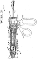
- the proximal portion of the outer tubular sheath 160 is preferably provided with a pair of wrench flats 240 (see FIGURE 4).
- the wrench flats allow torque to be applied by a suitable torque wrench or the like to thereby permit the waveguide 180 to be joined to the ultrasonic drive unit 50.
- a support member embodying the principles of the present invention desirably isolates the ultrasonic vibration transmitted through waveguide 180 from the surrounding sheath, in particular, tubular actuating member 170.
- Disposition of the present support member at the distal-most node of the waveguide desirably resists bending moments created in the waveguide as the clamping mechanism of the apparatus is operated.
- Disposition at the distal-most node of the waveguide also effects sealing of the region between the waveguide and the actuating member. While formation of the present support member from silicone rubber is presently preferred, it will be understood that other materials may alternatively be employed.
Abstract
Description
- The present invention relates generally to ultrasonic surgical devices, and more particularly to an ultrasonic surgical clamp coagulator apparatus for coagulating and/or cutting tissue, including an improved thin-walled support and sealing member for the ultrasonic waveguide of the apparatus which resists bending moments created during clamping of tissue against an end-effector of the waveguide.
- Ultrasonic surgical instruments are finding increasingly widespread applications in surgical procedures by virtue of the unique performance characteristics of such instruments. Depending upon specific instrument configurations and operational parameters, ultrasonic surgical instruments can provide substantially simultaneous cutting of tissue and hemostasis by coagulation, desirably minimizing patient trauma. The cutting action is typically effected by an end-effector at the distal end of the instrument, with the end-effector transmitting ultrasonic energy to tissue brought into contact therewith. Ultrasonic instruments of this nature can be configured for open surgical use, or laparoscopic or endoscopic surgical procedures.
- Ultrasonic surgical instruments have been developed that include a clamp mechanism to press tissue against the end-effector of the instrument in order to couple ultrasonic energy to the tissue of a patient. Such an arrangement (sometimes referred to as an ultrasonic transector) is disclosed in U.S. Patent No. 5,322,055, hereby incorporated by reference.
- In previous ultrasonic instruments, the waveguide of the instrument, through which ultrasonic energy is directed, is typically provided with one or more ring-like members for acoustically dampening the waveguide, and isolating the waveguide from surrounding components. Such isolation members are typically provided at one or more nodes of longitudinal vibration of the waveguide, and are typically constructed of elastomeric material, such as silicone rubber. Isolation members of this type desirably prevent loss of vibrational energy from the waveguide which can occur under side-loading or bending conditions which might otherwise cause indirect contact of the waveguide with an associated componept positioned thereabout.
- In ultrasonic surgical instruments heretofore known for endoscopic applications, the outside diameter of the elongated endoscopic portion of such instruments has been on the order of 10 mm. As such, it is ordinarily been possible to provide suitable isolation members for the waveguide of such instruments, while still providing a waveguide having a sufficiently large cross-section for the desired rigidity and for delivery of the desired level of ultrasonic energy without excessive heating of the waveguide.
- Continued development of ultrasonic surgical instruments has desirably resulted in instruments having even smaller endoscopic portions, on the order of 6 mm in diameter or less. When configuring ultrasonic instruments of this relatively small size, it is important that the desired acoustic dampening of the waveguide be effected, while still providing the waveguide with a cross-section which is as large as practicable. Problems in isolating the waveguide can be particularly exacerbated in ultrasonic instruments configured to effect clamping of tissue against an end-effector of the instrument, since such clamping creates bending moments within the waveguide flexing the waveguide from its normal, unloaded configuration.
- The present invention is directed to an improved support member for an ultrasonic surgical instrument, with the support member of the present invention particularly suited for use in instruments configured for endoscopic applications having relatively small cross-sections.
- In accordance with the present invention, an ultrasonic surgical clamp coagulator apparatus is configured to permit selective cutting, coagulation, and clamping of tissue during surgical procedures. In order to acoustically dampen the waveguide of the apparatus, the apparatus includes an annular support member positioned at the distal-most node of the waveguide. The annular support member is configured to include a support portion which acts to isolate the waveguide from surrounding components, and a sealing portion which effects sealing between the waveguide apd a reciprocable tubular actuating member positioned around the waveguide. By this construction, the annular support member dampens unwanted modes of vibration while allowing desired modes of vibration, effects sealing of the region about the waveguide, and maximizes the cross-sectional area available for the active waveguide within the elongated tubular portion of the instrument.
- In accordance with the illustrated embodiment, the present ultrasonic surgical clamp apparatus includes a housing, and an outer tubular sheath having a proximal end joined to the housing. An inner tubular actuating member is reciprocably positioned within the outer tubular sheath, and is operatively connected to a clamp arm pivotally mounted on a distal end of the outer tubular sheath. The clamp arm is mounted for pivotal movement with respect to an end-effector of an ultrasonic waveguide positioned within the inner tubular actuating member. In the illustrated embodiment, the outer tubular sheath, the inner tubular actuating member, and the ultrasonic waveguide are mounted for rotation together with respect to the apparatus housing, with the actuating member being reciprocable with respect to both the outer tubular sheath as well as the ultrasonic waveguide positioned within the actuating member. Reciprocable movement of the actuating member pivotally moves the clamp arm with respect to the end-effector of the waveguide.
- In accordance with the present invention, an annular support member is mounted on the waveguide at a distal-most node thereof. The support member preferably comprises elastomeric material, such as silicone rubber, and is configured to provide a combination of functions for enhancing the performance of the apparatus. Specifically, the support member includes a support portion having a generally cylindrical outer support surface which is positioned between the waveguide and the actuating member for resisting bending moments created during clamping of tissue against the end-effector by the pivotal clamp arm. The support member further includes a sealing portion for sealing the region between the waveguide and the relatively reciprocable actuating member. In the preferred embodiment, the sealing portion has a pair of converging surfaces which converge and meet each other to define a peripheral sealing region spaced radially outwardly of the outer cylindrical support surface of the support portion of the member.
- In accordance with illustrated embodiments of the invention, the sealing portion of the support member is spaced axially from the support portion thereof, either distally or proximally. In alternate embodiments, the sealing portion of the support member is positioned medially of the support portion. For each of the various embodiments of the support member, the associated waveguide can be configured to include a lug portion having a diameter greater than the portions of the waveguide adjacent thereto. The support member of the present invention is preferably positioned with respect to such a lug portion so that this support portion of the support member is positioned on and flanks the lug portion of the waveguide. In those embodiments of the present support member wherein the sealing portion is positioned medially of the support portion, the sealing portion can be positioned in substantial alignment with the lug portion of the waveguide.
- Other features and advantages of the present invention will become readily apparent from the following detailed description, the accompanying drawings, and the appended claims.
-
- FIGURE 1 is a perspective view of an ultrasonic surgical system including an ultrasonic clamp coagulator apparatus embodying the principles of the present invention;
- FIGURE 2 is an enlarged, fragmentary perspective view of a clamp mechanism of the clamp coagulator apparatus illustrated in FIGURE 1;
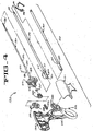
- FIGURE 3 is a side elevational view, partially in cut-away, of the clamp coagulator embodying the principles of the present invention, shown in operative association with an ultrasonic drive unit of the surgical system shown in FIGURE 1;
- FIGURE 4 is an exploded view of the ultrasonic surgical clamp coagulator apparatus embodying the principles of the present invention;
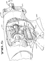
- FIGURE 5 is an enlarged, fragmentary view of the present clamp coagulator apparatus illustrating a clamp drive mechanism thereof and associated detent mechanism;
- FIGURE 6 is a diagrammatic view further illustrating the clamp drive mechanism and detent mechanism of the present clamp coagulator apparatus;
- FIGURE 7 is a diagrammatic view of the detent mechanism of the present invention;
- FIGURE 8 is a perspective view of a clamp mechanism drive collar of the present clamp coagulator apparatus;
- FIGURE 9 is a fragmentary, exploded perspective view illustrating a waveguide of the present apparatus, having a support member positioned thereon embodying the principles of the present invention, illustrated with an associated reciprocable actuating member of the apparatus; and
- FIGURES 10-15 are fragmentary cross-sectional views of the waveguide illustrated in FIGURE 9, with various embodiments of the support member of the present invention illustrated in position on the waveguide.
-
- While the present invention is susceptible of embodiments in various forms, there is shown in the drawings and will hereinafter be described a presently preferred embodiment, with the understanding that the present disclosure is to be considered as an exemplification of the invention, and is not intended to limit the invention to the specific embodiment illustrated.
- The present invention is particularly directed to an improved ultrasonic surgical clamp coagulator apparatus which is configured for effecting tissue cutting, coagulation, and/or clamping during surgical procedures. The present apparatus can readily be configured for use in both open surgical procedures, as well as laparoscopic or endoscopic procedures. Versatile use is facilitated by selective use of ultrasonic energy. When ultrasonic components of the apparatus are inactive, tissue can be readily gripped and manipulated, as desired, without tissue cutting or damage. When the ultrasonic components are activated, the apparatus permits tissue to be gripped for coupling with the ultrasonic energy to effect tissue coagulation, with application of increased pressure efficiently effecting tissue cutting and coagulation. If desired, ultrasonic energy can be applied to tissue without use of the clamping mechanism of the apparatus by appropriate manipulation of the ultrasonic "blade" or end-effector of the device.
- As will become apparent from the following description, the present clamp coagulator apparatus is particularly configured for disposable use by virtue of its straightforward construction. As such, it is contemplated that the apparatus be used in association with an ultrasonic drive unit of a surgical system, whereby ultrasonic energy from the drive unit provides the desired ultrasonic actuation of the present clamp coagulator apparatus. It will be appreciated that a clamp coagulator apparatus embodying the principles of the present invention can be configured for non-disposable use, and non-detachably integrated with an associated ultrasonic drive unit. However, detachable connection of the present clamp coagulator apparatus with an associated ultrasonic drive unit is presently preferred for single-patient use of the apparatus.
- With reference first to FIGURES 1 and 3, therein is illustrated a presently preferred embodiment of a surgical system, generally designated 10, which includes an ultrasonic clamp coagulator apparatus embodying the principles of the present invention. Preferred details of the ultrasonic generator and associated ultrasonic drive unit of the
surgical system 10 will first be described, with subsequent detailed description of the ultrasonic surgical clamp coagulator apparatus, including a clamp mechanism configured for indexed rotation, embodying the principles of the present invention. - The
surgical system 10 includes anultrasonic generator 30 and an associated ultrasonic surgical instrument. The surgical instrument includes an ultrasonic drive unit, designated 50, and an ultrasonicclamp coagulator apparatus 120 embodying the principles of the present invention. As will be further described, an ultrasonic transducer of thedrive unit 50, and an ultrasonic waveguide of theclamp coagulator 120, together provide an acoustic assembly of the present surgical system, with the acoustic assembly providing ultrasonic energy for surgical procedures when powered bygenerator 30. It will be noted that in some applications, theultrasonic drive unit 50 is referred to as a "hand piece assembly" because the surgical instrument of the surgical system is configured such that a surgeon grasps and manipulates theultrasonic drive unit 50 during various procedures and operations. Theclamp coagulator apparatus 120 embodying the principles of the present invention preferably includes a scissors-like grip arrangement which facilitates positioning and manipulation of the instrument apart from manipulation of theultrasonic drive unit 50. - The
generator 30 of the surgical system sends an electrical signal through acable 32 at a selected excursion, frequency, and phase determined by a control system of thegenerator 30. As will be further described, the signal causes one or more piezoelectric elements of the acoustic assembly of the surgical instrument to expand and contract, thereby converting the electrical energy into mechanical motion. The mechanical motion results in longitudinal waves of ultrasonic energy that propagate through the acoustic assembly in an acoustic standing wave to vibrate the acoustic assembly at a selected frequency and excursion. An end-effector at the distal end of the waveguide of the acoustic assembly is placed in contact with tissue of the patient to transfer the ultrasonic energy to the tissue. As further described below, a surgical tool, such as, a jaw or clamping mechanism, is preferably utilized to press the tissue against the end-effector. - As the end-effector couples with the tissue, thermal energy or heat is generated as a result of friction, acoustic absorption, and viscous losses within the tissue. The heat is sufficient to break protein hydrogen bonds, causing the highly structured protein (i.e., collagen and muscle protein) to denature (i.e., become less organized). As the proteins are denatured, a sticky coagulum forms to seal or coagulate small blood vessels. Deep coagulation of larger blood vessels results when the effect is prolonged.
- The transfer of the ultrasonic energy to the tissue causes other effects including mechanical tearing, cutting, cavitation, cell disruption, and emulsification. The amount of cutting as well as the degree of coagulation obtained varies with the excursion of the end-effector, the frequency of vibration, the amount of pressure applied by the user, the sharpness of the end-effector, and the coupling between the end-effector and the tissue.
- As illustrated in FIGURE 1, the
generator 30 includes a control system integral with thegenerator 30, apower switch 34, and a triggeringmechanism 36. Thepower switch 34 controls the electrical power to thegenerator 30, and when activated by the triggeringmechanism 36, thegenerator 30 provides energy to drive the acoustic assembly of thesurgical system 10 at a predetermined frequency and to drive the end-effector at a predetermined excursion level. Thegenerator 30 drives or excites the acoustic assembly at any suitable resonant frequency of the acoustic assembly. - When the
generator 30 is activated via the triggeringmechanism 36, electrical energy is continuously applied by thegenerator 30 to a transducer stack or assembly 40 of the acoustic assembly. A phase-locked loop in the control system of thegenerator 30 monitors feedback from the acoustic assembly. The phase lock loop adjusts the frequency of the electrical energy sent by thegenerator 30 to match the resonant frequency of the selected longitudinal mode of vibration of the acoustic assembly including the tissue load. In addition, a second feedback loop in the control system maintains the electrical current supplied to the acoustic assembly at a preselected constant level in order to achieve substantially constant excursion at the end-effector of the acoustic assembly. - The electrical signal supplied to the acoustic assembly will cause the distal end of the waveguide, i.e., the end-effector, to vibrate longitudinally in the range of, for example, approximately 20 kHz to 250 kHz, and preferably in the range of about 54 kHz to 56 kHz, and most preferably at about 55.5 kHz. The excursion of the vibrations at the end-effector can be controlled by, for example, controlling the amplitude of the electrical signal applied to the transducer assembly 40 of the acoustic assembly by the
generator 30. - As noted above, the triggering
mechanism 36 of thegenerator 30 allows a user to activate thegenerator 30 so that electrical energy may be continuously supplied to the acoustic assembly. The triggeringmechanism 36 preferably comprises a foot activating switch that is detachably coupled or attached to thegenerator 30 by a cable or cord. Alternatively, the triggering mechanism can be configured as a hand switch incorporated in theultrasonic drive unit 50 to allow thegenerator 30 to be activated by a user. - The
generator 30 also has apower line 38 for insertion in an electrosurgical unit or conventional electrical outlet. It is contemplated that thegenerator 30 can also be powered by a direct current (DC) source, such as a battery. Thegenerator 30 can comprise any suitable generator, such as Model No. GENO1, available from Ethicon Endo-Surgery, Inc. - Referring to FIGS. 1 and 3, the
ultrasonic drive unit 50 of the surgical instrument includes a multi-piece housing 52 adapted to isolate the operator from the vibrations of the acoustic assembly. The drive unit housing 52 can be shaped to be held by a user in a conventional manner, but it is contemplated that thepresent clamp coagulator 120 principally be grasped and manipulated by a scissors-like arrangement provided by a housing of the apparatus, as will be described. While the multi-piece housing 52 is illustrated, the housing 52 may comprise a single or unitary component. - The housing 52 of the
ultrasonic drive unit 50 generally includes a proximal end, a distal end, and a cavity extending longitudinally therein. The distal end of the housing 52 includes anopening 60 configured to allow the acoustic assembly of thesurgical system 10 to extend therethrough, and the proximal end of the housing 52 is coupled to thegenerator 30 by thecable 32. Thecable 32 preferably includes ducts or vents 62 to allow air to be introduced into the housing 52 of theultrasonic drive unit 50 to cool the transducer assembly 40 of the acoustic assembly. - The housing 52 of the
ultrasonic drive unit 50 is preferably constructed from a durable plastic, such as Ultem®. It is also contemplated that the housing 52 may alternatively be made from a variety of materials including other plastics [i.e. liquid crystal polymer (LCP), nylon, or polycarbonate]. A suitableultrasonic drive unit 50 is Model No. HP050, available from Ethicon Endo-Surgery, Inc. - The acoustic assembly of the surgical instrument generally includes a first acoustic portion and a second acoustic portion. The first acoustic portion is preferably carried by the
ultrasonic drive unit 50, and the second acoustic portion (in the form of a waveguide and end-effector, as will be described) is carried by the ultrasonic clamp coagulator apparatus. The distal end of the first acoustic portion is operatively coupled to the proximal end of the second acoustic portion preferably by a threaded connection. - As shown in FIGURE 3, the first acoustic portion includes the transducer stack or assembly 40 and a mounting device 84, and the second acoustic portion includes a transmission component or working member, referred to herein as a waveguide having an end-effector.
- The components of the acoustic assembly are preferably acoustically tuned such that the length of each component is an integral number of one-half wavelengths (nλ/2), where the wavelength λ is the wavelength of a preselected or operating longitudinal vibration frequency f0 of the acoustic assembly, and n is any non-negative integer. It is also contemplated that the acoustic assembly may incorporate any suitable arrangement of acoustic elements.
- The transducer assembly 40 of the acoustic assembly converts the electrical signal from the
generator 30 into mechanical energy that results in longitudinal vibratory motion of the end-effector at ultrasonic frequencies. When the acoustic assembly is energized, a vibratory motion standing wave is generated through the acoustic assembly. The excursion of the vibratory motion at any point along the acoustic assembly depends on the location along the acoustic assembly at which the vibratory motion is measured. A minimum or zero crossing in the vibratory motion standing wave is generally referred to as a node (i.e., where motion is usually minimal), and an absolute value maximum or peak in the standing wave is generally referred to as an anti-node. The distance between an anti-node and its nearest node is one-quarter wavelength (λ/4). - As shown in FIGURE 3, the transducer assembly 40 of the acoustic assembly, which is also known as a "Langevin stack", generally includes a
transduction portion 90, afirst resonator 92, and asecond resonator 94. The transducer assembly is preferably an integral number of one-half system wavelengths (nλ/2) in length. It is to be understood that the present invention may be alternatively configured to include a transducer assembly comprising a magnetostrictive, electromagnetic or electrostatic transducer. - The distal end of the
first resonator 92 is connected to the proximal end oftransduction section 90, and the proximal end of thesecond resonator 94 is connected to the distal end oftransduction portion 90. The first andsecond resonators first resonator 92 is fabricated from 303 stainless steel and thesecond resonator 94 is fabricated from 7075-T651 Aluminum. The first andsecond resonators transduction section 90, the speed of sound of material used in theresonators second resonator 94 can be tapered inwardly from its proximal end to its distal end to function as a velocity transformer and amplify the ultrasonic vibration excursion. - The
transduction portion 90 of the transducer assembly 40 preferably comprises a piezoelectric section of alternatingpositive electrodes 96 andnegative electrodes 98, withpiezoelectric elements 100 alternating between theelectrodes piezoelectric elements 100 can be fabricated from any suitable material, such as, for example, lead zirconate-titanate, lead meta-niobate, lead titanate, or other piezoelectric material. Each of thepositive electrodes 96,negative electrodes 98, andpiezoelectric elements 100 have a bore extending through the center. The positive andnegative electrodes wires 102 and 104, respectfully. Thewires 102 and 104 transmit the electrical signal from thegenerator 30 toelectrodes - As illustrated in FIGURE 3, the
piezoelectric elements 100 are held in compression between the first andsecond resonators bolt 106. Thebolt 106 preferably has a head, a shank, and a threaded distal end. Thebolt 106 is inserted from the proximal end of thefirst resonator 92 through the bores of thefirst resonator 92, theelectrodes piezoelectric elements 100. The threaded distal end of thebolt 106 is screwed into a threaded bore in the proximal end ofsecond resonator 94. The bolt can be fabricated from steel, titanium, aluminum, or other suitable material and is preferably fabricated from Ti-6Al-4V Titanium, and most preferably from 4037 low alloy steel. - The
piezoelectric elements 100 are energized in response to the electrical signal supplied from thegenerator 30 to produce an acoustic standing wave in the acoustic assembly. The electrical signal causes an electro-magnetic field across thepiezoelectric elements 100, causing thepiezoelectric elements 100 to expand and contract in a continuous manner along the axis of the voltage gradient, producing high frequency longitudinal waves of ultrasonic energy. The ultrasonic energy is transmitted through the acoustic assembly to the end-effector. - The mounting device 84 of the acoustic assembly has a proximal end, a distal end, and preferably has a length substantially equal to an integral number of one-half system wavelengths. The proximal end of the mounting device 84 is preferably axially aligned and coupled to the distal end of the
second resonator 94 by an internal threaded connection near an anti-node. (For purposes of this disclosure, the term "near" is defined as "exactly at" or "in close proximity to".) It is also contemplated that the mounting device 84 may be attached to thesecond resonator 94 by any suitable means, and thesecond resonator 94 and mounting device 84 may be formed as a single or unitary component. - The mounting device 84 is coupled to the housing 52 of the
ultrasonic drive unit 50 near a node. The mounting device 84 preferably includes anintegral mounting flange 108 disposed around its periphery. The mountingflange 108 is preferably disposed in anannular groove 110 formed in the housing 52 of theultrasonic drive unit 50 to couple the mounting device 84 to the housing 52. A compliant member ormaterial 112, such as a pair of silicone rubber O-rings attached by stand-offs, may be placed between theannular groove 110 of the housing 52 and theintegral flange 108 of the mounting device 86 to reduce or prevent ultrasonic vibration from being transmitted from the mounting device 84 to the housing 52. - The mounting device 84 is preferably secured in a predetermined axial position by a plurality of pins 114, preferably four. The pins 114 are disposed in a longitudinal direction ninety (90) degrees apart from each other around the outer periphery of the mounting device 84. The pins 114 are coupled to the housing 52 of the
ultrasonic drive unit 50 and are disposed through notches in the acoustic mountingflange 108 of the mounting device 84. The pins 114 are preferably fabricated from stainless steel. - The mounting device 84 is preferably configured to amplify the ultrasonic vibration excursion that is transmitted through the acoustic assembly to the distal end of the end-effector. In one preferred embodiment, the mounting device 84 comprises a solid, tapered horn. As ultrasonic energy is transmitted through the mounting device 84, the velocity of the acoustic wave transmitted through the mounting device 84 is amplified. It is contemplated that the mounting device 84 be configured as any suitable shape, such as, for example, a stepped horn, a conical horn, an exponential horn, a unitary gain horn, or the like.
- As shown in FIGURE 3, the mounting device 84 is preferably acoustically coupled to the second acoustic portion of the ultrasonic
clamp coagulator apparatus 120. The distal end of the mounting device 84 is preferably coupled to the proximal end of the second acoustic portion by an internal threaded connection near an anti-node, but alternative coupling arrangements can be employed. - Referring now to FIGURE 4, an exploded view of the ultrasonic
clamp coagulator apparatus 120 of thesurgical system 10 in accordance with a preferred embodiment is illustrated. The proximal end of the ultrasonicclamp coagulator apparatus 120 preferably receives and is fitted to the distal end of theultrasonic drive unit 50 by insertion of the drive unit into the housing of the apparatus, as shown in FIGURE 3. The ultrasonicclamp coagulator apparatus 120 is preferably attached to and removed from theultrasonic drive unit 50 as a unit. Theultrasonic clamp coagulator 120 may be disposed of after a single use. - The ultrasonic
clamp coagulator apparatus 120 preferably includes a handle assembly or ahousing 130, preferably comprisingmating housing portions 131, 132, and an elongated orendoscopic portion 150. When the present apparatus is configured for endoscopic use, the construction can be dimensioned such thatportion 150 has an outside diameter of about 5.5 mm. Theelongated portion 150 of the ultrasonicclamp coagulator apparatus 120 extends orthogonally from theapparatus housing 130. Theelongated portion 150 can be selectively rotated with respect to thehousing 130 as further described below. Theelongated portion 150 preferably includes an outer tubular member orsheath 160, an innertubular actuating member 170, and the second acoustic portion of the acoustic system in the form of awaveguide 180 having an end-effector 180'. As will be described, theouter sheath 160, the actuatingmember 170, and thewaveguide 180 are preferably joined together for indexed rotation as a unit (together with ultrasonic drive unit 50) relative tohousing 130. - As illustrated in FIGURE 4, the proximal end of the
waveguide 180 of the second acoustic portion is preferably detachably coupled to the mounting device 84 of theultrasonic drive unit 50 near an anti-node as described above. Thewaveguide 180 preferably has a length substantially equal to an integer number of one-half system wavelengths (nλ/2). Thewaveguide 180 is preferably fabricated from a solid core shaft constructed out of material which propagates ultrasonic energy efficiently, such as titanium alloy (i.e., Ti-6Al-4V) or an aluminum alloy. It is contemplated that thewaveguide 180 can alternatively be fabricated from any other suitable material. - The waveguide is preferably substantially semi-flexible. It will be recognized that the waveguide can alternatively be substantially rigid or may comprise a flexible wire. The waveguide may be configured to amplify the mechanical vibrations transmitted through the waveguide to the end-effector as is well known in the art. The waveguide may further have features to control the gain of the longitudinal vibration along the waveguide and features to tune the waveguide to the resonant frequency of the system.
- It will be recognized that the
waveguide 180 may have any suitable cross-sectional dimension. For example, the waveguide may have a substantially uniform cross-section or the waveguide may be tapered at various sections or may be tapered along its entire length. - As shown in FIGURE 4, the
waveguide 180 generally has afirst section 182, asecond section 184, and a third section 186. Thefirst section 182 of the waveguide extends distally from the proximal end of the waveguide, and has a substantially continuous cross-section dimension. - The
first section 182 preferably includes at least one radial hole oraperture 188 extending diametrically therethrough, substantially perpendicular to the axis of thewaveguide 180. Theaperture 188 is preferably positioned at a node, but may be otherwise positioned. It will be recognized that theaperture 188 may have any suitable depth and may be any suitable shape. The aperture is configured to receive a connector pin member which connects thewaveguide 180, thetubular actuating member 170, and the tubularouter sheath 160 together for conjoint, indexed rotation relative toapparatus housing 130. - The
second section 184 of thewaveguide 180 extends distally from thefirst section 182. Thesecond section 184 preferably also has a substantially continuous cross-section. The diameter of thesecond section 184 is smaller than the diameter of thefirst section 182 and larger than the diameter of the third section 186. As ultrasonic energy passes from thefirst section 182 of thewaveguide 180 into thesecond section 184, the narrowing of thesecond section 184 will result in an increased amplitude of the ultrasonic energy passing therethrough. - The third section 186 extends distally from the distal end of the
second section 184. The third section 186 also has a substantially continuous cross-section. The third section 186 may also include small diameter changes along its length. As ultrasonic energy passes from thesecond section 184 of thewaveguide 180 into the third section 186, the narrowing of the third section 186 will result in an increased amplitude of the ultrasonic energy passing therethrough. - The third section 186 may have a plurality of grooves or notches (not shown) formed in its outer circumference. The grooves may be located at nodes of the
waveguide 180 to act as alignment indicators for the installation of a damping sheath (not shown) and stabilizing silicone rings or compliant supports during manufacturing. Such compliant supports desirably act to isolate theactive waveguide 180 form surrounding components of the apparatus. A seal is preferably provided at the distal-most node, nearest the end-effector 180', to abate passage of tissue, blood, and other material in the region between the waveguide and actuatingmember 170. As further described hereinafter, and in accordance with the present invention, a support member is preferably provided at the distal-most node to resist bending moments created in the waveguide by the associated clamping mechanism, and to effect sealing of the region between the waveguide and actuatingmember 170. Even though it is contemplated that the support member be relatively thin (with regions as thin as about 0.003 to 0.005 inches) to provide the desired support, acoustic isolation of the active waveguide from actuatingmember 170 is effected. - The end-effector 180' of the
waveguide 180 is preferably integral therewith and formed as a single unit. The end-effector may alternately be connected by a threaded connection, or by a welded joint. The distal end of the end-effector is disposed near an anti-node in order to tune the acoustic assembly to a preferred resonant frequency f0 when the acoustic assembly is not loaded by tissue. When the transducer assembly is energized, the distal end of the end-effector is configured to move longitudinally in the range of, for example, approximately 10-500 microns peak-to-peak, and preferably in the range of about 10 to about 100 microns at a predetermined vibrational frequency f0. - In accordance with the illustrated embodiment, the end-effector 180', sometimes referred to as a blade, is preferably cylindrical for cooperation with the associated clamping mechanism of the present clamp coagulator apparatus. The end-effector may receive suitable surface treatment, as is known in the art.
- With particular reference to FIGURE 2, therein is illustrated the clamping mechanism of the
present clamp coagulator 120, which is configured for cooperative action with the end-effector 180' of thewaveguide 180. The clamping mechanism includes a pivotallymovable clamp arm 190, which is pivotally connected at the distal end thereof to the distal end of outertubular sheath 160. Aclamp pad 192, preferably formed from Teflon or other suitable low-friction material, is mounted on the surface of the clamp arm for cooperation with the end-effector 180', with pivotal movement of the clamp arm positioning the clamp pad in substantially parallel relationship to, and in contact with, the end-effector 180'. By this construction, tissue to be clamped is grasped between thepad 192 and the end effector 180'. As illustrated, thepad 192 is preferably provided with a sawtooth-like configuration to enhance the gripping of tissue in cooperation with the end-effector 180'. - Pivotal movement of the clamp arm with respect to the end-effector is effected by the provision of at least one, and preferably a pair of
lever portions 193 of theclamp arm 190 at the proximal end thereof. The lever portions are positioned on respective opposite sides of thewaveguide 180 and end-effector 180', and are in operative engagement with adrive portion 194 of thereciprocable actuating member 170. Reciprocable movement of the actuating member, relative to the outertubular sheath 160 and thewaveguide 180, thereby effects pivotal movement of the clamp arm relative to the end-effector. Thelever portions 193 can be respectively positioned in a pair of openings defined by thedrive portion 194, or otherwise suitably mechanically coupled therewith, whereby reciprocable movement of the actuating member acts through thedrive portion 194 andlever portions 193 to pivot the clamp arm. - With particular reference to FIGURES 3, 5, and 6, reciprocable movement of the actuating
member 170 is effected by the provision of a drive collar, generally designated 200, mounted on the proximal end of the actuating member for conjoint rotation. To this end, the drive collar includes a pair of diametrically opposed axially extendingarms 202 each having a drive lug 204, with the drive lugs being biased by thearms 202 into engagement withsuitable openings 206 defined by the proximal portion oftubular actuating member 170. Rotation of thedrive collar 200 together with the actuatingmember 170 is further effected by the provision of a pair of keys 208 (see FIGURE 8) diametrically engageable withsuitable openings 210 defined by the proximal end of the actuatingmember 170. A circumferential groove 211 on the actuatingmember 170 receives on O-ring 211' (FIGURE 4) for engagement with the inside surface ofouter sheath 160. - Rotation of the actuating
member 170 together with tubularouter sheath 160 andinner waveguide 180 is provided by aconnector pin 212 extending through these components of the apparatus. As illustrated in FIGURE 4, thetubular actuating member 170 defines anelongated slot 214 through which theconnector pin 212 extends to accommodate reciprocable movement of the actuating member relative to the outer tubular sheath and inner waveguide. - A
rotation knob 216 mounted on the outer tubular sheath facilitates rotational positioning of theelongated portion 150 with respect to thehousing 130 of the clamp coagulator apparatus.Connector pin 212 preferably joinsknob 216 together withsheath 160,member 170, andwaveguide 180 for rotation as a unit relative tohousing 130. In a current embodiment, hub portion 216' of the rotation knob acts to rotatably mount theouter sheath 160, the actuatingmember 170, and the waveguide 180 (as a unit with knob 216), on thehousing 130. - The
drive collar 200 provides a portion of the clamp drive mechanism of the apparatus which effects pivotal movement of theclamp arm 190 by reciprocation of actuatingmember 170. The clamp drive mechanism further includes adrive yoke 220 which is operatively connected with an operatinglever 222 of the apparatus, with the operating lever thus interconnected with thereciprocable actuating member 170 viadrive yoke 220 and drivecollar 200. The operatinglever 222 is pivotally connected to thehousing 130 of the apparatus (by a pivot mount 223) for cooperation in a scissors-like fashion with ahandgrip portion 224 of the housing. Movement oflever 222 towardhandgrip portion 224 translates actuatingmember 170 proximally, thereby pivotingclamp arm 190 toward end-effector 180'. - Operative connection of the
drive yoke 220 with the operatinglever 222 is provided by aspring 226, preferably comprising a compression coil spring. Thespring 226 fits within aspring slot 228 defined by thedrive yoke 220, which in turn is positioned between a pair ofspring retainer flanges 230 of the operatinglever 222. Thedrive yoke 220 is pivotally movable with respect to the spring flanges 230 (aboutpivot mount 223 of housing 130) in opposition to the compression coil spring, which bears against the surfaces of the spring slots defined by each of thespring flanges 230. In this manner, the force which can be applied to the actuatingmember 170, by pivotal movement ofoperating lever 222 acting throughdrive yoke 220 and drivecollar 200, is limited by the force with which spring 226 bears against thespring flanges 230. Application of excessive force results in pivotal displacement ofdrive yoke 220 relative to thespring flanges 230 of the operatinglever 222 in opposition tospring 226. In a presently preferred embodiment,spring 226 is selected to limit clamping force atclamp arm 190 to approximately 2 pounds. Stop portions ofhousing 130 limit the travel of operatinglever 222 to prevent excessive compression ofspring 226. - Indexed rotational positioning of the
elongated portion 150 of the presentclamp coagulator apparatus 120 is provided by the provision of a detent mechanism incorporated into the clamp drive mechanism of the apparatus. Specifically, thedrive collar 200 includes a pair of axially spaced apart drive flanges 232. A detent-receiving surface is provided between thedrive flanges 232, and defines a plurality of circumferentially spacedteeth 234 which define detent-receiving depressions generally about the periphery of thedrive collar 200. In a presently preferred embodiment, twelve (12) of theteeth 234 are provided, thereby providing indexed positioning of theelongated portion 150 of the apparatus at 30° intervals relative to thehousing 130 of the apparatus. - Indexed rotational movement is further achieved by the provision of at least one, and preferably a pair, of diametrically
opposed detents 236 respectively provided on cantileveredyoke arms 238 ofdrive yoke 220. By this arrangement, theyoke arms 238 are positioned between thedrive flanges 232 for engagement with the confronting surfaces thereof, and bias thedetents 236 into engagement with thedrive collar 200. Indexed relative rotation is thus achieved, with thedetents 236 of the yoke arms cooperating with thedrive flanges 238 for effecting reciprocation of the actuatingmember 170. In a presently preferred embodiment, thedrive yoke 220 is formed from suitable polymeric material, with the biasing force created by the yoke arms acting on the detents thereof cooperating with the radial depressions defined by the drive collar to resist relative rotational torque less than about 5 to 20 inch-ounces. As such, theelongated portion 150 of the clamp coagulator apparatus is maintained in any of its selected indexed rotational positions, relative tohousing 130, unless a torque is applied (such as by rotation knob 216) exceeding this predetermined torque level. A snap-like indexing action is thus provided. - Rotation of the
elongated proportion 150 of the presentclamp coagulator apparatus 120 is preferably effected together with relative rotational movement ofultrasonic drive unit 50 with respect toapparatus housing 130. In order to join theelongated portion 150 to theultrasonic drive unit 50 in ultrasonic-transmitting relationship, the proximal portion of the outertubular sheath 160 is preferably provided with a pair of wrench flats 240 (see FIGURE 4). The wrench flats allow torque to be applied by a suitable torque wrench or the like to thereby permit thewaveguide 180 to be joined to theultrasonic drive unit 50. The ultrasonic drive unit, as well as theelongated portion 150, are thus rotatable, as a unit, by suitable manipulation ofrotation knob 216, relative tohousing 130 of the apparatus. The interior ofhousing 130 is dimensioned to accommodate such relative rotation of thedrive unit 50. - As noted above, the present surgical clamp coagulator apparatus preferably includes a support member positioned at the distal-most node of the
waveguide 180 to resist bending moments created in the waveguide by pivotal movement ofclamp arm 190 against end-effector 180'. A support member, designated 250 in FIGURES 9-15, and embodying the principles of the present invention, is particularly preferred by virtue of the combination of support and sealing functions provided by the support member. The support member has been particularly configured to permit thewaveguide 180 to be provided with a relatively large cross-sectional area, even though the outertubular sheath 160 ofelongated portion 150 of the present surgical apparatus is preferably provided with an outside diameter less than about 6 mm. The support member desirably acts to acoustically isolate theactive waveguide 180 from the surrounding actuatingmember 170, while providing support to resist bending moments created in the waveguide, as well as effecting sealing between the waveguide and the relatively reciprocable actuating member. - As illustrated in FIGURES 9 and 10, the
annular support member 250 includes anannular support portion 252 having a generally cylindrical outer support surface which is positioned for engagement with the interior ofreciprocable support member 170. Thesupport member 250 is preferably formed from elastomeric material, such a silicone rubber, thus providing the desired compliance for the sealing function of the support member. However, it is contemplated that thesupport portion 252 be formed sufficiently thin to minimize its compression to aid in resisting bending moments created in the waveguide, particularly at the distal-most node thereof, asclamp arm 190 presses tissue against end-effector 180'. It is contemplated that the thickness of the support portion, at its thinnest region, be on the order of 0.003-0.005 inches, and formed from material exhibiting a durometer on the order of 60 Shore A. Even when configured to include such relatively thin regions, the support member still provides desired acoustic isolation for the waveguide. - As illustrated, the
support member 250 further includes an integralannular sealing portion 254. In the embodiments of thesupport member 250 illustrated in FIGURES 10 and 11, the sealingportion 254 is spaced axially distally from thesupport portion 252. As shown, the sealingportion 254 preferably includes a pair of converging surfaces (each preferably generally frusto-conical), which converge and meet each other to define a thin and compliant peripheral sealing region of the sealingportion 254. In a non-compressed state, this sealing region is spaced radially outwardly of the support surface of thesupport portion 252. This preferred configuration of the sealing member accommodates reciprocation oftubular actuating member 170 with respect to thewaveguide 180, while desirably sealing the region between the waveguide and the actuating member against fluids and other material encountered in surgery. It is preferred that anannular recess 255 be providedintermediate support portion 252 and sealing portion 154 (in those embodiments in which the sealing portion is spaced axially of the support portion) to accommodate deflection of the sealing portion toward the support portion attendant to relative reciprocation of the actuatingmember 170. - As shown, the sealing
member 250 is preferably positioned with respect to the distal-most node, designated "N" in the illustrations, such that thesupport portion 252 is generally centered with respect to the node. As will be observed, the embodiment of FIGURE 11 differs from the embodiment of FIGURE 10, in that thewaveguide 180 is provided with alug portion 181 having an outside diameter which is greater than the portions of the waveguide adjacent to the lug portion. In this embodiment ofsupport member 250, thesupport portion 252 is preferably centered at the node "N", and is positioned on and flanks the lug portion of the waveguide. The lug portion acts to maintain the support member in position of the waveguide attendant to relative reciprocation of actuatingmember 170. - Referring now to the embodiments of FIGURES 12 and 13, the embodiments of the
support member 250 illustrated therein are generally similar to the embodiments illustrated in FIGURES 10 and 11, respectively. However, the embodiments of FIGURES 12 and 13 differ in that the sealingportion 254 of each illustratedsupport member 250 is spaced axially proximally of thecorresponding support portion 252. Again, in the embodiment illustrated in FIGURE 13 whereinwaveguide 180 includes alug portion 181, thesupport portion 252 is preferably positioned on and flanks the lug portion. - Referring now to FIGURES 14 and 15, further alternate.embodiments of the present support member, designated 350, are illustrated. Each of these embodiments also include a support portion, designated 352, having a generally cylindrical outer support surface. These embodiments further include a sealing portion, designated 354, having a pair of converging surfaces which converge and meet to define a peripheral sealing region spaced radially outwardly of the outer support surface. In distinction from previous embodiments, these embodiments include a sealing
portion 354 which is positioned medially of thesupport portion 352. In the embodiment of FIGURE 15, whereinwaveguide 180 includes alug portion 181, the sealingportion 354 is positioned in substantial alignment with the lug portion of the waveguide. - A support member embodying the principles of the present invention desirably isolates the ultrasonic vibration transmitted through
waveguide 180 from the surrounding sheath, in particular,tubular actuating member 170. Disposition of the present support member at the distal-most node of the waveguide desirably resists bending moments created in the waveguide as the clamping mechanism of the apparatus is operated. Disposition at the distal-most node of the waveguide also effects sealing of the region between the waveguide and the actuating member. While formation of the present support member from silicone rubber is presently preferred, it will be understood that other materials may alternatively be employed. - Thus, the present surgical clamp coagulator apparatus is configured for highly efficient and versatile use, with the construction being sufficiently straight-forward and economical in configuration to permit single-patient use. Components of the apparatus can be fabricated from materials suited for surgical applications. By virtue of the detent mechanism provided by cooperation of
drive collar 200 and driveyoke 220, selective angular positioning of theelongated portion 150 of the apparatus, and the associatedultrasonic drive unit 50, is readily effected with respect to thehousing 130 of the apparatus. The scissors-like action provided bypivotal operating lever 222 and cooperatinghandgrip portion 224 facilitates convenient and efficient manipulation and positioning of the apparatus, and operation of the clamping mechanism at the distal portion of the apparatus whereby tissue is efficiently urged against the end-effector 180'. The detent mechanism resists rotation of the ultrasonic drive unit, and associated cable assembly, with respect to thehousing 130 with the resistence to rotation readily and conveniently overcome by application of sufficient torque viarotation knob 216. The preferred provision of a combination support and sealing member at the distal-most node of the apparatus further facilitate efficient operation and configuration of the instrument with a selectively small cross-section. - From the foregoing, it will be observed that numerous modifications and variations can be effected without departing from the true spirit and scope of the novel concept of the present invention. It is to be understood that no limitation with respect to the specific embodiment illustrated herein is intended or should be inferred. The disclosure is intended to cover, by the appended claims, all such modifications as fall within the scope of the claims.
Claims (14)
- An ultrasonic surgical clamp apparatus comprising:a housing;an outer tubular sheath having a proximal end joined to said housing, and a distal end;an inner actuating member reciprocably positioned within said outer tubular sheath;an ultrasonic waveguide positioned within said inner tubular actuating member and having an end-effector extending distally of said distal end of said outer tubular sheath, said actuating member being reciprocable relative to said waveguide;a clamp arm pivotally mounted on said distal end of said outer tubular sheath for pivotal movement with respect to said end-effector for clamping tissue between said clamp arm and said end-effector, said clamp arm being operatively connected to said actuating member so that reciprocable movement of said actuating member pivotally moves said clamp arm with respect to said end-effector; andan annular support member mounted on said waveguide at a distal-most node thereof for resisting bending moments created during clamping of tissue against said end-effector by said clamp arm, and for sealing the region between said waveguide and said relatively reciprocable actuating member.
- An ultrasonic surgical clamp apparatus in accordance with claim 1, whereinsaid support member includes a support portion having a generally cylindrical outer support surface, and a sealing portion having a pair of converging surfaces which converge to define a peripheral sealing region which in a non-compressed state is spaced radially outwardly of said outer support surface.
- An ultrasonic surgical clamp apparatus in accordance with claim 2, whereinsaid sealing portion of said support member is spaced axially from said support portion.
- An ultrasonic surgical clamp apparatus in accordance with claim 2 whereinsaid sealing portion of said support member is positioned medially of said support portion.
- An ultrasonic surgical clamp apparatus in accordance with claim 2, whereinsaid waveguide includes a lug portion at said distal-most node having an outer cylindrical surface having a diameter greater than portions of said waveguide adjacent to said lug portion, said support portion of said support member being positioned on and flanking said lug portion of said waveguide to maintain said support member in position on said waveguide attendant to relative reciprocation of said actuating member.
- An ultrasonic surgical clamp apparatus in accordance with claim 5, whereinsaid sealing portion of said support member is positioned medially of said support portion, and in substantial alignment with said lug portion of said waveguide.
- An ultrasonic surgical clamp apparatus in accordance with claim 1, whereina thinnest region of said support portion has a thickness of about 0.003-0.005 inches.
- An ultrasonic surgical clamp apparatus comprising:a housing;an outer tubular sheath having a proximal end joined to said housing, and a distal end,an inner actuating member reciprocably positioned within said outer tubular sheath;an ultrasonic waveguide positioned within said inner tubular actuating member and having an end-effector extending distally of said distal end of said outer tubular sheath, said actuating member being reciprocable relative to said waveguide;a clamp arm pivotally mounted on said distal end of said outer tubular sheath for pivotal movement with respect to said end-effector for clamping tissue between said clamp arm and said end-effector, said clamp arm being operatively connected to said actuating member so that reciprocable movement of said actuating member pivotally moves said clamp arm with respect to said end-effector; andan annular support member mounted on said waveguide at a distal-most node thereof for acoustically isolating said waveguide from said actuating member, said support member comprising elastomeric material and including a support portion positioned between said waveguide and actuating member for resisting bending moments created during clamping of tissue against said end-effector by said clamp arm, said support member further including a sealing portion spaced axially from said support portion for sealing the region between said waveguide and said relatively reciprocable actuating member.
- An ultrasonic surgical clamp apparatus in accordance with claim 8, whereinsaid support member includes a support portion having a generally cylindrical outer support surface, and a sealing portion having a pair of converging surfaces which converge to define a peripheral sealing region which, in a non-compressed state, is spaced radially outwardly of said outer support surface.
- An ultrasonic surgical clamp apparatus in accordance with claim 8, whereinsaid sealing portion of said support member is spaced distally of said support portion.
- An ultrasonic surgical clamp apparatus in accordance with claim 8, whereinsaid sealing portion of said support member is spaced proximally of said support portion.
- An ultrasonic surgical clamp apparatus in accordance with claim 8, whereinsaid waveguide includes a lug portion at said distal-most node having an outer cylindrical surface having a diameter greater than portions of said waveguide adjacent to said lug portion, said support portion of said support member being positioned on and flanking said lug portion of said waveguide to maintain said support member in position on said waveguide attendant to relative reciprocation of said actuating member.
- An ultrasonic surgical clamp apparatus in accordance with claim 8, whereinsaid outer tubular sheath has an outside diameter less than about 6 mm.
- An ultrasonic surgical clamp apparatus in accordance with claim 7, whereinsaid support member defines an annular recess positioned intermediate said support portion and said sealing portion for accommodating deflection of said sealing portion attendant to relative reciprocation of said actuating member.
Priority Applications (1)
| Application Number | Priority Date | Filing Date | Title |
|---|---|---|---|
| EP03012523A EP1362555B1 (en) | 1997-10-10 | 1998-10-09 | Ultrasonic clamp coagulator apparatus having improved waveguide support member |
Applications Claiming Priority (2)
| Application Number | Priority Date | Filing Date | Title |
|---|---|---|---|
| US949161 | 1997-10-10 | ||
| US08/949,161 US5944737A (en) | 1997-10-10 | 1997-10-10 | Ultrasonic clamp coagulator apparatus having improved waveguide support member |
Related Child Applications (1)
| Application Number | Title | Priority Date | Filing Date |
|---|---|---|---|
| EP03012523A Division EP1362555B1 (en) | 1997-10-10 | 1998-10-09 | Ultrasonic clamp coagulator apparatus having improved waveguide support member |
Publications (2)
| Publication Number | Publication Date |
|---|---|
| EP0908155A1 true EP0908155A1 (en) | 1999-04-14 |
| EP0908155B1 EP0908155B1 (en) | 2003-06-04 |
Family
ID=25488674
Family Applications (2)
| Application Number | Title | Priority Date | Filing Date |
|---|---|---|---|
| EP03012523A Revoked EP1362555B1 (en) | 1997-10-10 | 1998-10-09 | Ultrasonic clamp coagulator apparatus having improved waveguide support member |
| EP98308258A Expired - Lifetime EP0908155B1 (en) | 1997-10-10 | 1998-10-09 | Ultrasonic clamp coagulator apparatus having improved waveguide support member |
Family Applications Before (1)
| Application Number | Title | Priority Date | Filing Date |
|---|---|---|---|
| EP03012523A Revoked EP1362555B1 (en) | 1997-10-10 | 1998-10-09 | Ultrasonic clamp coagulator apparatus having improved waveguide support member |
Country Status (7)
| Country | Link |
|---|---|
| US (1) | US5944737A (en) |
| EP (2) | EP1362555B1 (en) |
| JP (2) | JP4488448B2 (en) |
| AU (1) | AU730054B2 (en) |
| CA (1) | CA2249809C (en) |
| DE (2) | DE69830674T2 (en) |
| ES (2) | ES2242914T3 (en) |
Cited By (27)
| Publication number | Priority date | Publication date | Assignee | Title |
|---|---|---|---|---|
| WO2011100328A1 (en) * | 2010-02-11 | 2011-08-18 | Ethicon Endo-Surgery, Inc. | Rotatable cutting implement arrangements for ultrasonic surgical instruments |
| EP2524660A1 (en) * | 2011-05-16 | 2012-11-21 | Tyco Healthcare Group LP | Medical ultrasound instrument with articulated jaws |
| US8662745B2 (en) | 2011-11-11 | 2014-03-04 | Covidien Lp | Methods of measuring conditions of an ultrasonic instrument |
| WO2015073428A1 (en) * | 2013-11-15 | 2015-05-21 | Ethicon Endo-Surgery, Inc. | Ultrasonic surgical instrument with integral blade cleaning feature |
| US9113943B2 (en) | 2011-03-30 | 2015-08-25 | Covidien Lp | Ultrasonic surgical instruments |
| US9351753B2 (en) | 2012-01-30 | 2016-05-31 | Covidien Lp | Ultrasonic medical instrument with a curved waveguide |
| US9918775B2 (en) | 2011-04-12 | 2018-03-20 | Covidien Lp | Systems and methods for calibrating power measurements in an electrosurgical generator |
| US10335182B2 (en) | 2012-06-29 | 2019-07-02 | Ethicon Llc | Surgical instruments with articulating shafts |
| US10335614B2 (en) | 2008-08-06 | 2019-07-02 | Ethicon Llc | Devices and techniques for cutting and coagulating tissue |
| US10335183B2 (en) | 2012-06-29 | 2019-07-02 | Ethicon Llc | Feedback devices for surgical control systems |
| US10342602B2 (en) | 2015-03-17 | 2019-07-09 | Ethicon Llc | Managing tissue treatment |
| US10349999B2 (en) | 2014-03-31 | 2019-07-16 | Ethicon Llc | Controlling impedance rise in electrosurgical medical devices |
| US10357303B2 (en) | 2015-06-30 | 2019-07-23 | Ethicon Llc | Translatable outer tube for sealing using shielded lap chole dissector |
| US10376305B2 (en) | 2016-08-05 | 2019-08-13 | Ethicon Llc | Methods and systems for advanced harmonic energy |
| US10398497B2 (en) | 2012-06-29 | 2019-09-03 | Ethicon Llc | Lockout mechanism for use with robotic electrosurgical device |
| US10398466B2 (en) | 2007-07-27 | 2019-09-03 | Ethicon Llc | Ultrasonic end effectors with increased active length |
| US10420579B2 (en) | 2007-07-31 | 2019-09-24 | Ethicon Llc | Surgical instruments |
| US10420580B2 (en) | 2016-08-25 | 2019-09-24 | Ethicon Llc | Ultrasonic transducer for surgical instrument |
| US10426507B2 (en) | 2007-07-31 | 2019-10-01 | Ethicon Llc | Ultrasonic surgical instruments |
| US10433900B2 (en) | 2011-07-22 | 2019-10-08 | Ethicon Llc | Surgical instruments for tensioning tissue |
| US10433866B2 (en) | 2007-11-30 | 2019-10-08 | Ethicon Llc | Ultrasonic surgical blades |
| US10441310B2 (en) | 2012-06-29 | 2019-10-15 | Ethicon Llc | Surgical instruments with curved section |
| US10441308B2 (en) | 2007-11-30 | 2019-10-15 | Ethicon Llc | Ultrasonic surgical instrument blades |
| US10441345B2 (en) | 2009-10-09 | 2019-10-15 | Ethicon Llc | Surgical generator for ultrasonic and electrosurgical devices |
| US10456193B2 (en) | 2016-05-03 | 2019-10-29 | Ethicon Llc | Medical device with a bilateral jaw configuration for nerve stimulation |
| US10463421B2 (en) | 2014-03-27 | 2019-11-05 | Ethicon Llc | Two stage trigger, clamp and cut bipolar vessel sealer |
| EP3629952B1 (en) * | 2017-05-22 | 2022-01-12 | Ethicon LLC | Combination ultrasonic and electrosurgical instrument having ultrasonic waveguide with distal overmold member |
Families Citing this family (273)
| Publication number | Priority date | Publication date | Assignee | Title |
|---|---|---|---|---|
| US20050143769A1 (en) * | 2002-08-19 | 2005-06-30 | White Jeffrey S. | Ultrasonic dissector |
| CA2213948C (en) | 1996-09-19 | 2006-06-06 | United States Surgical Corporation | Ultrasonic dissector |
| US6024750A (en) * | 1997-08-14 | 2000-02-15 | United States Surgical | Ultrasonic curved blade |
| US6159176A (en) * | 1997-12-11 | 2000-12-12 | Sonics & Materials Inc. | Sheath and support for ultrasonic elongate tip |
| US6096033A (en) * | 1998-07-20 | 2000-08-01 | Tu; Hosheng | Medical device having ultrasonic ablation capability |
| US6146353A (en) * | 1998-09-22 | 2000-11-14 | Sherwood Services Ag | Smoke extraction device |
| US6855123B2 (en) | 2002-08-02 | 2005-02-15 | Flow Cardia, Inc. | Therapeutic ultrasound system |
| US8506519B2 (en) | 1999-02-16 | 2013-08-13 | Flowcardia, Inc. | Pre-shaped therapeutic catheter |
| US6569178B1 (en) * | 1999-03-09 | 2003-05-27 | Olympus Optical Co., Ltd. | Ultrasonic coagulating/cutting apparatus |
| US20050119679A1 (en) * | 1999-10-05 | 2005-06-02 | Omnisonics Medical Technologies, Inc. | Apparatus and method for an ultrasonic medical device to treat chronic total occlusions |
| US6432118B1 (en) | 1999-10-05 | 2002-08-13 | Ethicon Endo-Surgery, Inc. | Multifunctional curved blade for use with an ultrasonic surgical instrument |
| JP4233742B2 (en) | 1999-10-05 | 2009-03-04 | エシコン・エンド−サージェリィ・インコーポレイテッド | Connecting curved clamp arms and tissue pads used with ultrasonic surgical instruments |
| US6325811B1 (en) * | 1999-10-05 | 2001-12-04 | Ethicon Endo-Surgery, Inc. | Blades with functional balance asymmetries for use with ultrasonic surgical instruments |
| US6679899B2 (en) * | 2000-10-20 | 2004-01-20 | Ethicon Endo-Surgery, Inc. | Method for detecting transverse vibrations in an ultrasonic hand piece |
| ES2285616T3 (en) * | 2000-12-15 | 2007-11-16 | Covidien Ag | ELECTROCHIRURGICAL ELECTRODE ENVELOPE. |
| US11229472B2 (en) | 2001-06-12 | 2022-01-25 | Cilag Gmbh International | Modular battery powered handheld surgical instrument with multiple magnetic position sensors |
| EP1524946B1 (en) | 2002-07-25 | 2012-10-17 | Covidien AG | Electrosurgical pencil with drag sensing capability |
| US8133236B2 (en) | 2006-11-07 | 2012-03-13 | Flowcardia, Inc. | Ultrasound catheter having protective feature against breakage |
| US9955994B2 (en) | 2002-08-02 | 2018-05-01 | Flowcardia, Inc. | Ultrasound catheter having protective feature against breakage |
| US7137963B2 (en) | 2002-08-26 | 2006-11-21 | Flowcardia, Inc. | Ultrasound catheter for disrupting blood vessel obstructions |
| US6942677B2 (en) | 2003-02-26 | 2005-09-13 | Flowcardia, Inc. | Ultrasound catheter apparatus |
| US7335180B2 (en) | 2003-11-24 | 2008-02-26 | Flowcardia, Inc. | Steerable ultrasound catheter |
| US7604608B2 (en) | 2003-01-14 | 2009-10-20 | Flowcardia, Inc. | Ultrasound catheter and methods for making and using same |
| US7220233B2 (en) | 2003-04-08 | 2007-05-22 | Flowcardia, Inc. | Ultrasound catheter devices and methods |
| US6747218B2 (en) | 2002-09-20 | 2004-06-08 | Sherwood Services Ag | Electrosurgical haptic switch including snap dome and printed circuit stepped contact array |
| US7244257B2 (en) | 2002-11-05 | 2007-07-17 | Sherwood Services Ag | Electrosurgical pencil having a single button variable control |
| EP1949867B1 (en) | 2003-02-20 | 2013-07-31 | Covidien AG | Motion detector for controlling electrosurgical output |
| US7025775B2 (en) * | 2003-05-15 | 2006-04-11 | Applied Medical Resources Corporation | Surgical instrument with removable shaft apparatus and method |
| US7758510B2 (en) * | 2003-09-19 | 2010-07-20 | Flowcardia, Inc. | Connector for securing ultrasound catheter to transducer |
| US7879033B2 (en) | 2003-11-20 | 2011-02-01 | Covidien Ag | Electrosurgical pencil with advanced ES controls |
| US7503917B2 (en) | 2003-11-20 | 2009-03-17 | Covidien Ag | Electrosurgical pencil with improved controls |
| US7156842B2 (en) | 2003-11-20 | 2007-01-02 | Sherwood Services Ag | Electrosurgical pencil with improved controls |
| US8182501B2 (en) | 2004-02-27 | 2012-05-22 | Ethicon Endo-Surgery, Inc. | Ultrasonic surgical shears and method for sealing a blood vessel using same |
| JP4249064B2 (en) * | 2004-03-10 | 2009-04-02 | オリンパス株式会社 | Endoscope |
| US7540852B2 (en) | 2004-08-26 | 2009-06-02 | Flowcardia, Inc. | Ultrasound catheter devices and methods |
| PL1802245T3 (en) * | 2004-10-08 | 2017-01-31 | Ethicon Endosurgery Llc | Ultrasonic surgical instrument |
| US8221343B2 (en) | 2005-01-20 | 2012-07-17 | Flowcardia, Inc. | Vibrational catheter devices and methods for making same |
| US8628534B2 (en) * | 2005-02-02 | 2014-01-14 | DePuy Synthes Products, LLC | Ultrasonic cutting device |
| US7500974B2 (en) | 2005-06-28 | 2009-03-10 | Covidien Ag | Electrode with rotatably deployable sheath |
| US7828794B2 (en) | 2005-08-25 | 2010-11-09 | Covidien Ag | Handheld electrosurgical apparatus for controlling operating room equipment |
| US20070191713A1 (en) | 2005-10-14 | 2007-08-16 | Eichmann Stephen E | Ultrasonic device for cutting and coagulating |
| US8152825B2 (en) * | 2005-10-14 | 2012-04-10 | Ethicon Endo-Surgery, Inc. | Medical ultrasound system and handpiece and methods for making and tuning |
| US7621930B2 (en) | 2006-01-20 | 2009-11-24 | Ethicon Endo-Surgery, Inc. | Ultrasound medical instrument having a medical ultrasonic blade |
| US9282984B2 (en) | 2006-04-05 | 2016-03-15 | Flowcardia, Inc. | Therapeutic ultrasound system |
| US20070260240A1 (en) | 2006-05-05 | 2007-11-08 | Sherwood Services Ag | Soft tissue RF transection and resection device |
| US20070282333A1 (en) | 2006-06-01 | 2007-12-06 | Fortson Reginald D | Ultrasonic waveguide and blade |
| US20080097501A1 (en) * | 2006-06-22 | 2008-04-24 | Tyco Healthcare Group Lp | Ultrasonic probe deflection sensor |
| US8246643B2 (en) | 2006-11-07 | 2012-08-21 | Flowcardia, Inc. | Ultrasound catheter having improved distal end |
| US8142461B2 (en) | 2007-03-22 | 2012-03-27 | Ethicon Endo-Surgery, Inc. | Surgical instruments |
| US20080234709A1 (en) | 2007-03-22 | 2008-09-25 | Houser Kevin L | Ultrasonic surgical instrument and cartilage and bone shaping blades therefor |
| US8911460B2 (en) | 2007-03-22 | 2014-12-16 | Ethicon Endo-Surgery, Inc. | Ultrasonic surgical instruments |
| US8226675B2 (en) | 2007-03-22 | 2012-07-24 | Ethicon Endo-Surgery, Inc. | Surgical instruments |
| US8257377B2 (en) | 2007-07-27 | 2012-09-04 | Ethicon Endo-Surgery, Inc. | Multiple end effectors ultrasonic surgical instruments |
| US8808319B2 (en) | 2007-07-27 | 2014-08-19 | Ethicon Endo-Surgery, Inc. | Surgical instruments |
| US8348967B2 (en) | 2007-07-27 | 2013-01-08 | Ethicon Endo-Surgery, Inc. | Ultrasonic surgical instruments |
| US8882791B2 (en) | 2007-07-27 | 2014-11-11 | Ethicon Endo-Surgery, Inc. | Ultrasonic surgical instruments |
| US8252012B2 (en) | 2007-07-31 | 2012-08-28 | Ethicon Endo-Surgery, Inc. | Ultrasonic surgical instrument with modulator |
| US9044261B2 (en) | 2007-07-31 | 2015-06-02 | Ethicon Endo-Surgery, Inc. | Temperature controlled ultrasonic surgical instruments |
| US8506565B2 (en) | 2007-08-23 | 2013-08-13 | Covidien Lp | Electrosurgical device with LED adapter |
| EP2217157A2 (en) | 2007-10-05 | 2010-08-18 | Ethicon Endo-Surgery, Inc. | Ergonomic surgical instruments |
| USD594983S1 (en) | 2007-10-05 | 2009-06-23 | Ethicon Endo-Surgery, Inc. | Handle assembly for surgical instrument |
| US7901423B2 (en) | 2007-11-30 | 2011-03-08 | Ethicon Endo-Surgery, Inc. | Folded ultrasonic end effectors with increased active length |
| US9107690B2 (en) | 2007-12-03 | 2015-08-18 | Covidien Ag | Battery-powered hand-held ultrasonic surgical cautery cutting device |
| US8419757B2 (en) * | 2007-12-03 | 2013-04-16 | Covidien Ag | Cordless hand-held ultrasonic cautery cutting device |
| US8061014B2 (en) | 2007-12-03 | 2011-11-22 | Covidien Ag | Method of assembling a cordless hand-held ultrasonic cautery cutting device |
| US8663262B2 (en) | 2007-12-03 | 2014-03-04 | Covidien Ag | Battery assembly for battery-powered surgical instruments |
| US8338726B2 (en) | 2009-08-26 | 2012-12-25 | Covidien Ag | Two-stage switch for cordless hand-held ultrasonic cautery cutting device |
| US9017355B2 (en) | 2007-12-03 | 2015-04-28 | Covidien Ag | Battery-powered hand-held ultrasonic surgical cautery cutting device |
| US9314261B2 (en) | 2007-12-03 | 2016-04-19 | Covidien Ag | Battery-powered hand-held ultrasonic surgical cautery cutting device |
| US8435257B2 (en) * | 2007-12-03 | 2013-05-07 | Covidien Ag | Cordless hand-held ultrasonic cautery cutting device and method |
| US8235987B2 (en) | 2007-12-05 | 2012-08-07 | Tyco Healthcare Group Lp | Thermal penetration and arc length controllable electrosurgical pencil |
| US20090216157A1 (en) * | 2008-02-22 | 2009-08-27 | Norihiro Yamada | Ultrasonic operating apparatus |
| US8663219B2 (en) | 2008-03-31 | 2014-03-04 | Covidien Lp | Electrosurgical pencil including improved controls |
| US8636733B2 (en) | 2008-03-31 | 2014-01-28 | Covidien Lp | Electrosurgical pencil including improved controls |
| US8597292B2 (en) | 2008-03-31 | 2013-12-03 | Covidien Lp | Electrosurgical pencil including improved controls |
| ES2428719T3 (en) | 2008-03-31 | 2013-11-11 | Applied Medical Resources Corporation | Electrosurgical system with means to measure tissue permittivity and conductivity |
| US8128646B2 (en) * | 2008-06-03 | 2012-03-06 | Olympus Medical Systems, Corp. | Ultrasonic vibration apparatus |
| US8162937B2 (en) | 2008-06-27 | 2012-04-24 | Tyco Healthcare Group Lp | High volume fluid seal for electrosurgical handpiece |
| US8058771B2 (en) | 2008-08-06 | 2011-11-15 | Ethicon Endo-Surgery, Inc. | Ultrasonic device for cutting and coagulating with stepped output |
| US20100057118A1 (en) * | 2008-09-03 | 2010-03-04 | Dietz Timothy G | Ultrasonic surgical blade |
| US8231620B2 (en) | 2009-02-10 | 2012-07-31 | Tyco Healthcare Group Lp | Extension cutting blade |
| US9700339B2 (en) | 2009-05-20 | 2017-07-11 | Ethicon Endo-Surgery, Inc. | Coupling arrangements and methods for attaching tools to ultrasonic surgical instruments |
| US8226566B2 (en) | 2009-06-12 | 2012-07-24 | Flowcardia, Inc. | Device and method for vascular re-entry |
| US8344596B2 (en) | 2009-06-24 | 2013-01-01 | Ethicon Endo-Surgery, Inc. | Transducer arrangements for ultrasonic surgical instruments |
| US8623040B2 (en) | 2009-07-01 | 2014-01-07 | Alcon Research, Ltd. | Phacoemulsification hook tip |
| US9017326B2 (en) | 2009-07-15 | 2015-04-28 | Ethicon Endo-Surgery, Inc. | Impedance monitoring apparatus, system, and method for ultrasonic surgical instruments |
| WO2011008672A2 (en) | 2009-07-15 | 2011-01-20 | Ethicon Endo-Surgery, Inc. | Electrosurgery generator for ultrasonic surgical instruments |
| US8461744B2 (en) | 2009-07-15 | 2013-06-11 | Ethicon Endo-Surgery, Inc. | Rotating transducer mount for ultrasonic surgical instruments |
| US8663220B2 (en) | 2009-07-15 | 2014-03-04 | Ethicon Endo-Surgery, Inc. | Ultrasonic surgical instruments |
| US9039695B2 (en) | 2009-10-09 | 2015-05-26 | Ethicon Endo-Surgery, Inc. | Surgical generator for ultrasonic and electrosurgical devices |
| USRE47996E1 (en) | 2009-10-09 | 2020-05-19 | Ethicon Llc | Surgical generator for ultrasonic and electrosurgical devices |
| US11090104B2 (en) | 2009-10-09 | 2021-08-17 | Cilag Gmbh International | Surgical generator for ultrasonic and electrosurgical devices |
| US10172669B2 (en) | 2009-10-09 | 2019-01-08 | Ethicon Llc | Surgical instrument comprising an energy trigger lockout |
| US9168054B2 (en) | 2009-10-09 | 2015-10-27 | Ethicon Endo-Surgery, Inc. | Surgical generator for ultrasonic and electrosurgical devices |
| US8579928B2 (en) | 2010-02-11 | 2013-11-12 | Ethicon Endo-Surgery, Inc. | Outer sheath and blade arrangements for ultrasonic surgical instruments |
| US8951272B2 (en) | 2010-02-11 | 2015-02-10 | Ethicon Endo-Surgery, Inc. | Seal arrangements for ultrasonically powered surgical instruments |
| US8531064B2 (en) | 2010-02-11 | 2013-09-10 | Ethicon Endo-Surgery, Inc. | Ultrasonically powered surgical instruments with rotating cutting implement |
| US8486096B2 (en) | 2010-02-11 | 2013-07-16 | Ethicon Endo-Surgery, Inc. | Dual purpose surgical instrument for cutting and coagulating tissue |
| US8961547B2 (en) | 2010-02-11 | 2015-02-24 | Ethicon Endo-Surgery, Inc. | Ultrasonic surgical instruments with moving cutting implement |
| US9259234B2 (en) | 2010-02-11 | 2016-02-16 | Ethicon Endo-Surgery, Llc | Ultrasonic surgical instruments with rotatable blade and hollow sheath arrangements |
| US8323302B2 (en) | 2010-02-11 | 2012-12-04 | Ethicon Endo-Surgery, Inc. | Methods of using ultrasonically powered surgical instruments with rotatable cutting implements |
| US8382782B2 (en) | 2010-02-11 | 2013-02-26 | Ethicon Endo-Surgery, Inc. | Ultrasonic surgical instruments with partially rotating blade and fixed pad arrangement |
| US8419759B2 (en) | 2010-02-11 | 2013-04-16 | Ethicon Endo-Surgery, Inc. | Ultrasonic surgical instrument with comb-like tissue trimming device |
| EP2374425B1 (en) | 2010-04-08 | 2012-07-04 | Stryker Trauma GmbH | Ultrasonic applicator |
| GB2480498A (en) | 2010-05-21 | 2011-11-23 | Ethicon Endo Surgery Inc | Medical device comprising RF circuitry |
| US8795327B2 (en) | 2010-07-22 | 2014-08-05 | Ethicon Endo-Surgery, Inc. | Electrosurgical instrument with separate closure and cutting members |
| US9192431B2 (en) | 2010-07-23 | 2015-11-24 | Ethicon Endo-Surgery, Inc. | Electrosurgical cutting and sealing instrument |
| US10258505B2 (en) | 2010-09-17 | 2019-04-16 | Alcon Research, Ltd. | Balanced phacoemulsification tip |
| JP6143362B2 (en) | 2010-10-01 | 2017-06-07 | アプライド メディカル リソーシーズ コーポレイション | Electrosurgical instrument with jaws and / or electrodes and electrosurgical amplifier |
| US8888809B2 (en) | 2010-10-01 | 2014-11-18 | Ethicon Endo-Surgery, Inc. | Surgical instrument with jaw member |
| US8979890B2 (en) | 2010-10-01 | 2015-03-17 | Ethicon Endo-Surgery, Inc. | Surgical instrument with jaw member |
| US9161803B2 (en) | 2010-11-05 | 2015-10-20 | Ethicon Endo-Surgery, Inc. | Motor driven electrosurgical device with mechanical and electrical feedback |
| US20120116381A1 (en) | 2010-11-05 | 2012-05-10 | Houser Kevin L | Surgical instrument with charging station and wireless communication |
| US9017849B2 (en) | 2010-11-05 | 2015-04-28 | Ethicon Endo-Surgery, Inc. | Power source management for medical device |
| US10881448B2 (en) | 2010-11-05 | 2021-01-05 | Ethicon Llc | Cam driven coupling between ultrasonic transducer and waveguide in surgical instrument |
| US9782215B2 (en) | 2010-11-05 | 2017-10-10 | Ethicon Endo-Surgery, Llc | Surgical instrument with ultrasonic transducer having integral switches |
| US9375255B2 (en) | 2010-11-05 | 2016-06-28 | Ethicon Endo-Surgery, Llc | Surgical instrument handpiece with resiliently biased coupling to modular shaft and end effector |
| US9039720B2 (en) | 2010-11-05 | 2015-05-26 | Ethicon Endo-Surgery, Inc. | Surgical instrument with ratcheting rotatable shaft |
| US9017851B2 (en) | 2010-11-05 | 2015-04-28 | Ethicon Endo-Surgery, Inc. | Sterile housing for non-sterile medical device component |
| US9649150B2 (en) | 2010-11-05 | 2017-05-16 | Ethicon Endo-Surgery, Llc | Selective activation of electronic components in medical device |
| US10959769B2 (en) | 2010-11-05 | 2021-03-30 | Ethicon Llc | Surgical instrument with slip ring assembly to power ultrasonic transducer |
| US9421062B2 (en) | 2010-11-05 | 2016-08-23 | Ethicon Endo-Surgery, Llc | Surgical instrument shaft with resiliently biased coupling to handpiece |
| US9782214B2 (en) | 2010-11-05 | 2017-10-10 | Ethicon Llc | Surgical instrument with sensor and powered control |
| US10660695B2 (en) | 2010-11-05 | 2020-05-26 | Ethicon Llc | Sterile medical instrument charging device |
| US20120116265A1 (en) | 2010-11-05 | 2012-05-10 | Houser Kevin L | Surgical instrument with charging devices |
| US9089338B2 (en) | 2010-11-05 | 2015-07-28 | Ethicon Endo-Surgery, Inc. | Medical device packaging with window for insertion of reusable component |
| US9011471B2 (en) | 2010-11-05 | 2015-04-21 | Ethicon Endo-Surgery, Inc. | Surgical instrument with pivoting coupling to modular shaft and end effector |
| US9381058B2 (en) | 2010-11-05 | 2016-07-05 | Ethicon Endo-Surgery, Llc | Recharge system for medical devices |
| US9597143B2 (en) | 2010-11-05 | 2017-03-21 | Ethicon Endo-Surgery, Llc | Sterile medical instrument charging device |
| US9072523B2 (en) | 2010-11-05 | 2015-07-07 | Ethicon Endo-Surgery, Inc. | Medical device with feature for sterile acceptance of non-sterile reusable component |
| US9510895B2 (en) | 2010-11-05 | 2016-12-06 | Ethicon Endo-Surgery, Llc | Surgical instrument with modular shaft and end effector |
| US10085792B2 (en) | 2010-11-05 | 2018-10-02 | Ethicon Llc | Surgical instrument with motorized attachment feature |
| US9000720B2 (en) | 2010-11-05 | 2015-04-07 | Ethicon Endo-Surgery, Inc. | Medical device packaging with charging interface |
| US9247986B2 (en) | 2010-11-05 | 2016-02-02 | Ethicon Endo-Surgery, Llc | Surgical instrument with ultrasonic transducer having integral switches |
| US9526921B2 (en) | 2010-11-05 | 2016-12-27 | Ethicon Endo-Surgery, Llc | User feedback through end effector of surgical instrument |
| USD668337S1 (en) * | 2010-11-15 | 2012-10-02 | Erbe Elektromedizin Gmbh | Electro-surgical clamp and cutting device |
| EP2688496B8 (en) | 2011-03-24 | 2019-09-11 | Ethicon LLC | Energy-based scissors device |
| US9114181B2 (en) | 2011-03-30 | 2015-08-25 | Covidien Lp | Process of cooling surgical device battery before or during high temperature sterilization |
| USD700699S1 (en) | 2011-08-23 | 2014-03-04 | Covidien Ag | Handle for portable surgical device |
| US20130085419A1 (en) | 2011-09-29 | 2013-04-04 | Tyco Healthcare Group Lp | Transducer/Waveguide Engagement Mechanisms for Ultrasonic Surgical Instruments |
| US9050125B2 (en) | 2011-10-10 | 2015-06-09 | Ethicon Endo-Surgery, Inc. | Ultrasonic surgical instrument with modular end effector |
| US8734476B2 (en) | 2011-10-13 | 2014-05-27 | Ethicon Endo-Surgery, Inc. | Coupling for slip ring assembly and ultrasonic transducer in surgical instrument |
| US9421060B2 (en) | 2011-10-24 | 2016-08-23 | Ethicon Endo-Surgery, Llc | Litz wire battery powered device |
| USD687549S1 (en) | 2011-10-24 | 2013-08-06 | Ethicon Endo-Surgery, Inc. | Surgical instrument |
| US9603615B2 (en) | 2012-01-18 | 2017-03-28 | C.R. Bard, Inc. | Vascular re-entry device |
| JP6165780B2 (en) | 2012-02-10 | 2017-07-19 | エシコン・エンド−サージェリィ・インコーポレイテッドEthicon Endo−Surgery,Inc. | Robot-controlled surgical instrument |
| US9237921B2 (en) | 2012-04-09 | 2016-01-19 | Ethicon Endo-Surgery, Inc. | Devices and techniques for cutting and coagulating tissue |
| US9724118B2 (en) | 2012-04-09 | 2017-08-08 | Ethicon Endo-Surgery, Llc | Techniques for cutting and coagulating tissue for ultrasonic surgical instruments |
| US9439668B2 (en) | 2012-04-09 | 2016-09-13 | Ethicon Endo-Surgery, Llc | Switch arrangements for ultrasonic surgical instruments |
| US9226766B2 (en) | 2012-04-09 | 2016-01-05 | Ethicon Endo-Surgery, Inc. | Serial communication protocol for medical device |
| US9241731B2 (en) | 2012-04-09 | 2016-01-26 | Ethicon Endo-Surgery, Inc. | Rotatable electrical connection for ultrasonic surgical instruments |
| US20140005705A1 (en) | 2012-06-29 | 2014-01-02 | Ethicon Endo-Surgery, Inc. | Surgical instruments with articulating shafts |
| US9283045B2 (en) | 2012-06-29 | 2016-03-15 | Ethicon Endo-Surgery, Llc | Surgical instruments with fluid management system |
| US9820768B2 (en) | 2012-06-29 | 2017-11-21 | Ethicon Llc | Ultrasonic surgical instruments with control mechanisms |
| US9226767B2 (en) | 2012-06-29 | 2016-01-05 | Ethicon Endo-Surgery, Inc. | Closed feedback control for electrosurgical device |
| US20140005702A1 (en) | 2012-06-29 | 2014-01-02 | Ethicon Endo-Surgery, Inc. | Ultrasonic surgical instruments with distally positioned transducers |
| US9351754B2 (en) | 2012-06-29 | 2016-05-31 | Ethicon Endo-Surgery, Llc | Ultrasonic surgical instruments with distally positioned jaw assemblies |
| EP2879596A2 (en) | 2012-08-02 | 2015-06-10 | Flowcardia, Inc. | Ultrasound catheter system |
| CN104853688B (en) | 2012-09-28 | 2017-11-28 | 伊西康内外科公司 | Multifunctional bipolar tweezers |
| US9241732B2 (en) | 2012-10-16 | 2016-01-26 | Covdien LP | Surgical instrument |
| US9095367B2 (en) | 2012-10-22 | 2015-08-04 | Ethicon Endo-Surgery, Inc. | Flexible harmonic waveguides/blades for surgical instruments |
| US10201365B2 (en) | 2012-10-22 | 2019-02-12 | Ethicon Llc | Surgeon feedback sensing and display methods |
| US20140135804A1 (en) | 2012-11-15 | 2014-05-15 | Ethicon Endo-Surgery, Inc. | Ultrasonic and electrosurgical devices |
| US10226273B2 (en) | 2013-03-14 | 2019-03-12 | Ethicon Llc | Mechanical fasteners for use with surgical energy devices |
| US9241728B2 (en) | 2013-03-15 | 2016-01-26 | Ethicon Endo-Surgery, Inc. | Surgical instrument with multiple clamping mechanisms |
| US9814514B2 (en) | 2013-09-13 | 2017-11-14 | Ethicon Llc | Electrosurgical (RF) medical instruments for cutting and coagulating tissue |
| US9265926B2 (en) | 2013-11-08 | 2016-02-23 | Ethicon Endo-Surgery, Llc | Electrosurgical devices |
| WO2015088012A1 (en) * | 2013-12-13 | 2015-06-18 | オリンパス株式会社 | Treatment instrument and treatment system |
| GB2521228A (en) | 2013-12-16 | 2015-06-17 | Ethicon Endo Surgery Inc | Medical device |
| GB2521229A (en) | 2013-12-16 | 2015-06-17 | Ethicon Endo Surgery Inc | Medical device |
| US9743946B2 (en) | 2013-12-17 | 2017-08-29 | Ethicon Llc | Rotation features for ultrasonic surgical instrument |
| US9795436B2 (en) | 2014-01-07 | 2017-10-24 | Ethicon Llc | Harvesting energy from a surgical generator |
| US9554854B2 (en) | 2014-03-18 | 2017-01-31 | Ethicon Endo-Surgery, Llc | Detecting short circuits in electrosurgical medical devices |
| US10092310B2 (en) | 2014-03-27 | 2018-10-09 | Ethicon Llc | Electrosurgical devices |
| US9913680B2 (en) | 2014-04-15 | 2018-03-13 | Ethicon Llc | Software algorithms for electrosurgical instruments |
| KR102537276B1 (en) | 2014-05-16 | 2023-05-26 | 어플라이드 메디컬 리소시스 코포레이션 | Electrosurgical system |
| KR102420273B1 (en) | 2014-05-30 | 2022-07-13 | 어플라이드 메디컬 리소시스 코포레이션 | Electrosurgical instrument for fusing and cutting tissue and an electrosurgical generator |
| US9700333B2 (en) | 2014-06-30 | 2017-07-11 | Ethicon Llc | Surgical instrument with variable tissue compression |
| US10285724B2 (en) | 2014-07-31 | 2019-05-14 | Ethicon Llc | Actuation mechanisms and load adjustment assemblies for surgical instruments |
| US10136938B2 (en) | 2014-10-29 | 2018-11-27 | Ethicon Llc | Electrosurgical instrument with sensor |
| JP6049953B2 (en) * | 2014-11-21 | 2016-12-21 | オリンパス株式会社 | Surgical instrument |
| US10639092B2 (en) | 2014-12-08 | 2020-05-05 | Ethicon Llc | Electrode configurations for surgical instruments |
| US10159524B2 (en) | 2014-12-22 | 2018-12-25 | Ethicon Llc | High power battery powered RF amplifier topology |
| US10420603B2 (en) | 2014-12-23 | 2019-09-24 | Applied Medical Resources Corporation | Bipolar electrosurgical sealer and divider |
| USD748259S1 (en) | 2014-12-29 | 2016-01-26 | Applied Medical Resources Corporation | Electrosurgical instrument |
| US10245095B2 (en) | 2015-02-06 | 2019-04-02 | Ethicon Llc | Electrosurgical instrument with rotation and articulation mechanisms |
| US10321950B2 (en) | 2015-03-17 | 2019-06-18 | Ethicon Llc | Managing tissue treatment |
| US10595929B2 (en) | 2015-03-24 | 2020-03-24 | Ethicon Llc | Surgical instruments with firing system overload protection mechanisms |
| US10314638B2 (en) | 2015-04-07 | 2019-06-11 | Ethicon Llc | Articulating radio frequency (RF) tissue seal with articulating state sensing |
| US10034684B2 (en) | 2015-06-15 | 2018-07-31 | Ethicon Llc | Apparatus and method for dissecting and coagulating tissue |
| US11020140B2 (en) | 2015-06-17 | 2021-06-01 | Cilag Gmbh International | Ultrasonic surgical blade for use with ultrasonic surgical instruments |
| US10898256B2 (en) | 2015-06-30 | 2021-01-26 | Ethicon Llc | Surgical system with user adaptable techniques based on tissue impedance |
| US11051873B2 (en) | 2015-06-30 | 2021-07-06 | Cilag Gmbh International | Surgical system with user adaptable techniques employing multiple energy modalities based on tissue parameters |
| US11129669B2 (en) | 2015-06-30 | 2021-09-28 | Cilag Gmbh International | Surgical system with user adaptable techniques based on tissue type |
| US10765470B2 (en) | 2015-06-30 | 2020-09-08 | Ethicon Llc | Surgical system with user adaptable techniques employing simultaneous energy modalities based on tissue parameters |
| US10034704B2 (en) | 2015-06-30 | 2018-07-31 | Ethicon Llc | Surgical instrument with user adaptable algorithms |
| US10154852B2 (en) | 2015-07-01 | 2018-12-18 | Ethicon Llc | Ultrasonic surgical blade with improved cutting and coagulation features |
| EP3355820A1 (en) | 2015-09-30 | 2018-08-08 | Ethicon LLC | Method and apparatus for selecting operations of a surgical instrument based on user intention |
| US11058475B2 (en) | 2015-09-30 | 2021-07-13 | Cilag Gmbh International | Method and apparatus for selecting operations of a surgical instrument based on user intention |
| BR112018006301B1 (en) | 2015-09-30 | 2023-01-24 | Ethicon Llc | METHOD FOR GENERATING ELECTRICAL SIGNAL WAVEFORMS BY A GENERATOR AND GENERATOR FOR GENERATING ELECTRICAL SIGNAL WAVEFORMS |
| US10595930B2 (en) | 2015-10-16 | 2020-03-24 | Ethicon Llc | Electrode wiping surgical device |
| US10959771B2 (en) | 2015-10-16 | 2021-03-30 | Ethicon Llc | Suction and irrigation sealing grasper |
| US10231749B2 (en) * | 2015-12-21 | 2019-03-19 | Ethicon Llc | Ultrasonic surgical instrument with blade replacement features |
| US10179022B2 (en) | 2015-12-30 | 2019-01-15 | Ethicon Llc | Jaw position impedance limiter for electrosurgical instrument |
| US10959806B2 (en) | 2015-12-30 | 2021-03-30 | Ethicon Llc | Energized medical device with reusable handle |
| US10575892B2 (en) | 2015-12-31 | 2020-03-03 | Ethicon Llc | Adapter for electrical surgical instruments |
| US11129670B2 (en) | 2016-01-15 | 2021-09-28 | Cilag Gmbh International | Modular battery powered handheld surgical instrument with selective application of energy based on button displacement, intensity, or local tissue characterization |
| US11229471B2 (en) | 2016-01-15 | 2022-01-25 | Cilag Gmbh International | Modular battery powered handheld surgical instrument with selective application of energy based on tissue characterization |
| US10716615B2 (en) | 2016-01-15 | 2020-07-21 | Ethicon Llc | Modular battery powered handheld surgical instrument with curved end effectors having asymmetric engagement between jaw and blade |
| US10709469B2 (en) | 2016-01-15 | 2020-07-14 | Ethicon Llc | Modular battery powered handheld surgical instrument with energy conservation techniques |
| US10555769B2 (en) | 2016-02-22 | 2020-02-11 | Ethicon Llc | Flexible circuits for electrosurgical instrument |
| US10485607B2 (en) | 2016-04-29 | 2019-11-26 | Ethicon Llc | Jaw structure with distal closure for electrosurgical instruments |
| US10987156B2 (en) | 2016-04-29 | 2021-04-27 | Ethicon Llc | Electrosurgical instrument with electrically conductive gap setting member and electrically insulative tissue engaging members |
| US10646269B2 (en) | 2016-04-29 | 2020-05-12 | Ethicon Llc | Non-linear jaw gap for electrosurgical instruments |
| US10702329B2 (en) | 2016-04-29 | 2020-07-07 | Ethicon Llc | Jaw structure with distal post for electrosurgical instruments |
| US10856934B2 (en) | 2016-04-29 | 2020-12-08 | Ethicon Llc | Electrosurgical instrument with electrically conductive gap setting and tissue engaging members |
| US10368898B2 (en) | 2016-05-05 | 2019-08-06 | Covidien Lp | Ultrasonic surgical instrument |
| US10245064B2 (en) | 2016-07-12 | 2019-04-02 | Ethicon Llc | Ultrasonic surgical instrument with piezoelectric central lumen transducer |
| US10893883B2 (en) | 2016-07-13 | 2021-01-19 | Ethicon Llc | Ultrasonic assembly for use with ultrasonic surgical instruments |
| US10842522B2 (en) | 2016-07-15 | 2020-11-24 | Ethicon Llc | Ultrasonic surgical instruments having offset blades |
| US10285723B2 (en) | 2016-08-09 | 2019-05-14 | Ethicon Llc | Ultrasonic surgical blade with improved heel portion |
| US10792064B2 (en) | 2016-08-12 | 2020-10-06 | Covidien Lp | Energy-based surgical instrument for treating tissue |
| USD847990S1 (en) | 2016-08-16 | 2019-05-07 | Ethicon Llc | Surgical instrument |
| US10952759B2 (en) | 2016-08-25 | 2021-03-23 | Ethicon Llc | Tissue loading of a surgical instrument |
| US10751117B2 (en) | 2016-09-23 | 2020-08-25 | Ethicon Llc | Electrosurgical instrument with fluid diverter |
| US20180140321A1 (en) | 2016-11-23 | 2018-05-24 | C. R. Bard, Inc. | Catheter With Retractable Sheath And Methods Thereof |
| US10603064B2 (en) * | 2016-11-28 | 2020-03-31 | Ethicon Llc | Ultrasonic transducer |
| US11266430B2 (en) | 2016-11-29 | 2022-03-08 | Cilag Gmbh International | End effector control and calibration |
| US10575917B2 (en) * | 2016-12-14 | 2020-03-03 | Ethicon Llc | Ultrasonic surgical instrument with integral torque wrench and transverse engagement |
| US11596726B2 (en) | 2016-12-17 | 2023-03-07 | C.R. Bard, Inc. | Ultrasound devices for removing clots from catheters and related methods |
| US10758256B2 (en) | 2016-12-22 | 2020-09-01 | C. R. Bard, Inc. | Ultrasonic endovascular catheter |
| US10582983B2 (en) | 2017-02-06 | 2020-03-10 | C. R. Bard, Inc. | Ultrasonic endovascular catheter with a controllable sheath |
| US11033325B2 (en) | 2017-02-16 | 2021-06-15 | Cilag Gmbh International | Electrosurgical instrument with telescoping suction port and debris cleaner |
| US10799284B2 (en) | 2017-03-15 | 2020-10-13 | Ethicon Llc | Electrosurgical instrument with textured jaws |
| US11497546B2 (en) | 2017-03-31 | 2022-11-15 | Cilag Gmbh International | Area ratios of patterned coatings on RF electrodes to reduce sticking |
| US10571435B2 (en) | 2017-06-08 | 2020-02-25 | Covidien Lp | Systems and methods for digital control of ultrasonic devices |
| US10603117B2 (en) | 2017-06-28 | 2020-03-31 | Ethicon Llc | Articulation state detection mechanisms |
| US10820920B2 (en) | 2017-07-05 | 2020-11-03 | Ethicon Llc | Reusable ultrasonic medical devices and methods of their use |
| US11033293B2 (en) | 2017-07-19 | 2021-06-15 | Cilag Gmbh International | Ultrasonic transducer to blade acoustic coupling, connections, and configurations |
| US10925630B2 (en) | 2018-06-19 | 2021-02-23 | Ethicon Llc | Surgical devices and systems with rotating end effector assemblies having an ultrasonic blade |
| US10582945B2 (en) | 2018-03-20 | 2020-03-10 | Ethicon Llc | Surgical devices and systems with rotating end effector assemblies having an ultrasonic blade |
| US11490951B2 (en) | 2017-09-29 | 2022-11-08 | Cilag Gmbh International | Saline contact with electrodes |
| US11033323B2 (en) | 2017-09-29 | 2021-06-15 | Cilag Gmbh International | Systems and methods for managing fluid and suction in electrosurgical systems |
| US11484358B2 (en) | 2017-09-29 | 2022-11-01 | Cilag Gmbh International | Flexible electrosurgical instrument |
| US11246621B2 (en) | 2018-01-29 | 2022-02-15 | Covidien Lp | Ultrasonic transducers and ultrasonic surgical instruments including the same |
| US11259832B2 (en) | 2018-01-29 | 2022-03-01 | Covidien Lp | Ultrasonic horn for an ultrasonic surgical instrument, ultrasonic surgical instrument including the same, and method of manufacturing an ultrasonic horn |
| US11246617B2 (en) | 2018-01-29 | 2022-02-15 | Covidien Lp | Compact ultrasonic transducer and ultrasonic surgical instrument including the same |
| US11229449B2 (en) | 2018-02-05 | 2022-01-25 | Covidien Lp | Ultrasonic horn, ultrasonic transducer assembly, and ultrasonic surgical instrument including the same |
| US10582944B2 (en) | 2018-02-23 | 2020-03-10 | Covidien Lp | Ultrasonic surgical instrument with torque assist feature |
| AU2019335013A1 (en) | 2018-09-05 | 2021-03-25 | Applied Medical Resources Corporation | Electrosurgical generator control system |
| EP3880099A1 (en) | 2018-11-16 | 2021-09-22 | Applied Medical Resources Corporation | Electrosurgical system |
| CN110403672A (en) * | 2019-05-01 | 2019-11-05 | 杭州康基医疗器械股份有限公司 | Ultrasonic medical surgical instruments |
| CN110123416A (en) * | 2019-05-01 | 2019-08-16 | 杭州康基医疗器械股份有限公司 | The floating support structure of ultrasonic transducer |
| US11478268B2 (en) | 2019-08-16 | 2022-10-25 | Covidien Lp | Jaw members for surgical instruments and surgical instruments incorporating the same |
| US11666357B2 (en) | 2019-09-16 | 2023-06-06 | Covidien Lp | Enclosure for electronics of a surgical instrument |
| US11564732B2 (en) | 2019-12-05 | 2023-01-31 | Covidien Lp | Tensioning mechanism for bipolar pencil |
| US11744636B2 (en) | 2019-12-30 | 2023-09-05 | Cilag Gmbh International | Electrosurgical systems with integrated and external power sources |
| US20210196361A1 (en) | 2019-12-30 | 2021-07-01 | Ethicon Llc | Electrosurgical instrument with monopolar and bipolar energy capabilities |
| US11937863B2 (en) | 2019-12-30 | 2024-03-26 | Cilag Gmbh International | Deflectable electrode with variable compression bias along the length of the deflectable electrode |
| US11911063B2 (en) | 2019-12-30 | 2024-02-27 | Cilag Gmbh International | Techniques for detecting ultrasonic blade to electrode contact and reducing power to ultrasonic blade |
| US11684412B2 (en) | 2019-12-30 | 2023-06-27 | Cilag Gmbh International | Surgical instrument with rotatable and articulatable surgical end effector |
| US11779329B2 (en) | 2019-12-30 | 2023-10-10 | Cilag Gmbh International | Surgical instrument comprising a flex circuit including a sensor system |
| US11944366B2 (en) | 2019-12-30 | 2024-04-02 | Cilag Gmbh International | Asymmetric segmented ultrasonic support pad for cooperative engagement with a movable RF electrode |
| US11452525B2 (en) | 2019-12-30 | 2022-09-27 | Cilag Gmbh International | Surgical instrument comprising an adjustment system |
| US11779387B2 (en) | 2019-12-30 | 2023-10-10 | Cilag Gmbh International | Clamp arm jaw to minimize tissue sticking and improve tissue control |
| US20210196363A1 (en) | 2019-12-30 | 2021-07-01 | Ethicon Llc | Electrosurgical instrument with electrodes operable in bipolar and monopolar modes |
| US11696776B2 (en) | 2019-12-30 | 2023-07-11 | Cilag Gmbh International | Articulatable surgical instrument |
| US11660089B2 (en) | 2019-12-30 | 2023-05-30 | Cilag Gmbh International | Surgical instrument comprising a sensing system |
| US11812957B2 (en) | 2019-12-30 | 2023-11-14 | Cilag Gmbh International | Surgical instrument comprising a signal interference resolution system |
| US11786294B2 (en) | 2019-12-30 | 2023-10-17 | Cilag Gmbh International | Control program for modular combination energy device |
| US11786291B2 (en) | 2019-12-30 | 2023-10-17 | Cilag Gmbh International | Deflectable support of RF energy electrode with respect to opposing ultrasonic blade |
| US20220117623A1 (en) | 2020-10-15 | 2022-04-21 | Covidien Lp | Ultrasonic surgical instrument |
| US11717312B2 (en) | 2021-10-01 | 2023-08-08 | Covidien Lp | Surgical system including blade visualization markings |
Citations (2)
| Publication number | Priority date | Publication date | Assignee | Title |
|---|---|---|---|---|
| US5322055A (en) | 1993-01-27 | 1994-06-21 | Ultracision, Inc. | Clamp coagulator/cutting system for ultrasonic surgical instruments |
| US5346502A (en) * | 1993-04-15 | 1994-09-13 | Ultracision, Inc. | Laparoscopic ultrasonic surgical instrument and methods for manufacturing the instruments |
Family Cites Families (17)
| Publication number | Priority date | Publication date | Assignee | Title |
|---|---|---|---|---|
| US30536A (en) * | 1860-10-30 | The graphic co | ||
| US2874470A (en) * | 1954-05-28 | 1959-02-24 | James R Richards | High frequency dental tool |
| NL113902C (en) * | 1958-08-29 | 1900-01-01 | ||
| US3368280A (en) * | 1966-03-23 | 1968-02-13 | C & B Inc | Dental tool |
| US3488851A (en) * | 1968-04-18 | 1970-01-13 | Zoltan Haydu | Ultrasonic devices |
| US4370131A (en) * | 1977-06-24 | 1983-01-25 | Surgical Design | Ultrasonic transducer tips |
| US4522206A (en) * | 1983-01-26 | 1985-06-11 | Dyonics, Inc. | Surgical instrument |
| US4750488A (en) * | 1986-05-19 | 1988-06-14 | Sonomed Technology, Inc. | Vibration apparatus preferably for endoscopic ultrasonic aspirator |
| JP2660008B2 (en) * | 1988-07-28 | 1997-10-08 | オリンパス光学工業株式会社 | Ultrasound therapy equipment |
| JPH02141425U (en) * | 1989-04-28 | 1990-11-28 | ||
| US5433725A (en) * | 1991-12-13 | 1995-07-18 | Unisurge, Inc. | Hand-held surgical device and tools for use therewith, assembly and method |
| WO1993014708A1 (en) * | 1992-02-03 | 1993-08-05 | Ultracision Inc. | Laparoscopic surgical apparatus and methods using ultrasonic energy |
| DE4444403A1 (en) * | 1994-12-14 | 1996-06-20 | Waizenegger Klaus | Surgical instrument |
| JPH08275949A (en) * | 1995-04-05 | 1996-10-22 | Olympus Optical Co Ltd | Ultrasonic dissecting and coagulating device |
| JP3310532B2 (en) * | 1995-04-06 | 2002-08-05 | オリンパス光学工業株式会社 | Ultrasonic incision coagulation device |
| JP3354032B2 (en) * | 1995-04-06 | 2002-12-09 | オリンパス光学工業株式会社 | Surgical forceps and ultrasonic coagulation and incision device |
| JP3686117B2 (en) * | 1995-04-06 | 2005-08-24 | オリンパス株式会社 | Ultrasonic incision coagulator |
-
1997
- 1997-10-10 US US08/949,161 patent/US5944737A/en not_active Expired - Lifetime
-
1998
- 1998-10-06 CA CA002249809A patent/CA2249809C/en not_active Expired - Lifetime
- 1998-10-09 AU AU88415/98A patent/AU730054B2/en not_active Expired
- 1998-10-09 ES ES03012523T patent/ES2242914T3/en not_active Expired - Lifetime
- 1998-10-09 EP EP03012523A patent/EP1362555B1/en not_active Revoked
- 1998-10-09 DE DE69830674T patent/DE69830674T2/en not_active Expired - Lifetime
- 1998-10-09 EP EP98308258A patent/EP0908155B1/en not_active Expired - Lifetime
- 1998-10-09 DE DE69815246T patent/DE69815246T2/en not_active Expired - Lifetime
- 1998-10-09 JP JP30173198A patent/JP4488448B2/en not_active Expired - Lifetime
- 1998-10-09 ES ES98308258T patent/ES2201414T3/en not_active Expired - Lifetime
-
2008
- 2008-05-28 JP JP2008139318A patent/JP4832468B2/en not_active Expired - Lifetime
Patent Citations (3)
| Publication number | Priority date | Publication date | Assignee | Title |
|---|---|---|---|---|
| US5322055A (en) | 1993-01-27 | 1994-06-21 | Ultracision, Inc. | Clamp coagulator/cutting system for ultrasonic surgical instruments |
| US5322055B1 (en) | 1993-01-27 | 1997-10-14 | Ultracision Inc | Clamp coagulator/cutting system for ultrasonic surgical instruments |
| US5346502A (en) * | 1993-04-15 | 1994-09-13 | Ultracision, Inc. | Laparoscopic ultrasonic surgical instrument and methods for manufacturing the instruments |
Cited By (36)
| Publication number | Priority date | Publication date | Assignee | Title |
|---|---|---|---|---|
| US10398466B2 (en) | 2007-07-27 | 2019-09-03 | Ethicon Llc | Ultrasonic end effectors with increased active length |
| US10426507B2 (en) | 2007-07-31 | 2019-10-01 | Ethicon Llc | Ultrasonic surgical instruments |
| US10420579B2 (en) | 2007-07-31 | 2019-09-24 | Ethicon Llc | Surgical instruments |
| US10433866B2 (en) | 2007-11-30 | 2019-10-08 | Ethicon Llc | Ultrasonic surgical blades |
| US10433865B2 (en) | 2007-11-30 | 2019-10-08 | Ethicon Llc | Ultrasonic surgical blades |
| US10463887B2 (en) | 2007-11-30 | 2019-11-05 | Ethicon Llc | Ultrasonic surgical blades |
| US10441308B2 (en) | 2007-11-30 | 2019-10-15 | Ethicon Llc | Ultrasonic surgical instrument blades |
| US10335614B2 (en) | 2008-08-06 | 2019-07-02 | Ethicon Llc | Devices and techniques for cutting and coagulating tissue |
| US10441345B2 (en) | 2009-10-09 | 2019-10-15 | Ethicon Llc | Surgical generator for ultrasonic and electrosurgical devices |
| WO2011100328A1 (en) * | 2010-02-11 | 2011-08-18 | Ethicon Endo-Surgery, Inc. | Rotatable cutting implement arrangements for ultrasonic surgical instruments |
| US9113943B2 (en) | 2011-03-30 | 2015-08-25 | Covidien Lp | Ultrasonic surgical instruments |
| US9918775B2 (en) | 2011-04-12 | 2018-03-20 | Covidien Lp | Systems and methods for calibrating power measurements in an electrosurgical generator |
| US8894674B2 (en) | 2011-05-16 | 2014-11-25 | Covidien Lp | Medical ultrasound instrument with articulated jaws |
| US8444664B2 (en) | 2011-05-16 | 2013-05-21 | Covidien Lp | Medical ultrasound instrument with articulated jaws |
| EP2524660A1 (en) * | 2011-05-16 | 2012-11-21 | Tyco Healthcare Group LP | Medical ultrasound instrument with articulated jaws |
| US10433900B2 (en) | 2011-07-22 | 2019-10-08 | Ethicon Llc | Surgical instruments for tensioning tissue |
| US8662745B2 (en) | 2011-11-11 | 2014-03-04 | Covidien Lp | Methods of measuring conditions of an ultrasonic instrument |
| US9351753B2 (en) | 2012-01-30 | 2016-05-31 | Covidien Lp | Ultrasonic medical instrument with a curved waveguide |
| US10335182B2 (en) | 2012-06-29 | 2019-07-02 | Ethicon Llc | Surgical instruments with articulating shafts |
| US10335183B2 (en) | 2012-06-29 | 2019-07-02 | Ethicon Llc | Feedback devices for surgical control systems |
| US10441310B2 (en) | 2012-06-29 | 2019-10-15 | Ethicon Llc | Surgical instruments with curved section |
| US10398497B2 (en) | 2012-06-29 | 2019-09-03 | Ethicon Llc | Lockout mechanism for use with robotic electrosurgical device |
| US9901358B2 (en) | 2013-11-15 | 2018-02-27 | Ethicon Llc | Ultrasonic surgical instrument with integral blade cleaning feature |
| CN105934208A (en) * | 2013-11-15 | 2016-09-07 | 伊西康内外科有限责任公司 | Ultrasonic surgical instrument with integral blade cleaning feature |
| CN105934208B (en) * | 2013-11-15 | 2019-08-16 | 伊西康内外科有限责任公司 | Ultrasonic surgical instrument with one-piece blade cleaning feature structure |
| EP3524191A1 (en) * | 2013-11-15 | 2019-08-14 | Ethicon LLC | Ultrasonic surgical instrument with integral blade cleaning feature |
| WO2015073428A1 (en) * | 2013-11-15 | 2015-05-21 | Ethicon Endo-Surgery, Inc. | Ultrasonic surgical instrument with integral blade cleaning feature |
| US10463421B2 (en) | 2014-03-27 | 2019-11-05 | Ethicon Llc | Two stage trigger, clamp and cut bipolar vessel sealer |
| US10349999B2 (en) | 2014-03-31 | 2019-07-16 | Ethicon Llc | Controlling impedance rise in electrosurgical medical devices |
| US10342602B2 (en) | 2015-03-17 | 2019-07-09 | Ethicon Llc | Managing tissue treatment |
| US10357303B2 (en) | 2015-06-30 | 2019-07-23 | Ethicon Llc | Translatable outer tube for sealing using shielded lap chole dissector |
| US10456193B2 (en) | 2016-05-03 | 2019-10-29 | Ethicon Llc | Medical device with a bilateral jaw configuration for nerve stimulation |
| US10376305B2 (en) | 2016-08-05 | 2019-08-13 | Ethicon Llc | Methods and systems for advanced harmonic energy |
| US10420580B2 (en) | 2016-08-25 | 2019-09-24 | Ethicon Llc | Ultrasonic transducer for surgical instrument |
| EP3629952B1 (en) * | 2017-05-22 | 2022-01-12 | Ethicon LLC | Combination ultrasonic and electrosurgical instrument having ultrasonic waveguide with distal overmold member |
| EP4005511A1 (en) * | 2017-05-22 | 2022-06-01 | Ethicon LLC | Combination ultrasonic and electrosurgical instrument having ultrasonic waveguide with distal overmold member |
Also Published As
| Publication number | Publication date |
|---|---|
| DE69815246T2 (en) | 2004-05-06 |
| DE69830674T2 (en) | 2006-05-24 |
| AU730054B2 (en) | 2001-02-22 |
| AU8841598A (en) | 1999-04-29 |
| ES2242914T3 (en) | 2005-11-16 |
| EP0908155B1 (en) | 2003-06-04 |
| US5944737A (en) | 1999-08-31 |
| ES2201414T3 (en) | 2004-03-16 |
| JP2008284374A (en) | 2008-11-27 |
| DE69830674D1 (en) | 2005-07-28 |
| DE69815246D1 (en) | 2003-07-10 |
| EP1362555B1 (en) | 2005-06-22 |
| JPH11192234A (en) | 1999-07-21 |
| EP1362555A1 (en) | 2003-11-19 |
| CA2249809C (en) | 2007-12-11 |
| CA2249809A1 (en) | 1999-04-10 |
| JP4832468B2 (en) | 2011-12-07 |
| JP4488448B2 (en) | 2010-06-23 |
Similar Documents
| Publication | Publication Date | Title |
|---|---|---|
| EP0908155B1 (en) | Ultrasonic clamp coagulator apparatus having improved waveguide support member | |
| EP0908148B1 (en) | Ultrasonic clamp coagulator apparatus having indexed rotational positioning | |
| US5873873A (en) | Ultrasonic clamp coagulator apparatus having improved clamp mechanism | |
| US5980510A (en) | Ultrasonic clamp coagulator apparatus having improved clamp arm pivot mount | |
| EP0908149B1 (en) | Ultrasonic clamp coagulator apparatus having clamp arm tissue pad | |
| EP0908152B1 (en) | Ultrasonic clamp coagulator apparatus having force-limiting clamping mechanism | |
| EP1308133A1 (en) | Ultrasonic clamp coagulator apparatus having dual rotational positioning | |
| EP0908154B1 (en) | Ultrasonic clamp coagulator apparatus having housing for rotatably supporting ultrasonic components |
Legal Events
| Date | Code | Title | Description |
|---|---|---|---|
| PUAI | Public reference made under article 153(3) epc to a published international application that has entered the european phase |
Free format text: ORIGINAL CODE: 0009012 |
|
| AK | Designated contracting states |
Kind code of ref document: A1 Designated state(s): DE ES FR GB IT NL |
|
| AX | Request for extension of the european patent |
Free format text: AL;LT;LV;MK;RO;SI |
|
| 17P | Request for examination filed |
Effective date: 19990920 |
|
| AKX | Designation fees paid |
Free format text: DE ES FR GB IT NL |
|
| 17Q | First examination report despatched |
Effective date: 20011026 |
|
| GRAH | Despatch of communication of intention to grant a patent |
Free format text: ORIGINAL CODE: EPIDOS IGRA |
|
| GRAH | Despatch of communication of intention to grant a patent |
Free format text: ORIGINAL CODE: EPIDOS IGRA |
|
| GRAA | (expected) grant |
Free format text: ORIGINAL CODE: 0009210 |
|
| AK | Designated contracting states |
Designated state(s): DE ES FR GB IT NL |
|
| REG | Reference to a national code |
Ref country code: GB Ref legal event code: FG4D |
|
| RIN1 | Information on inventor provided before grant (corrected) |
Inventor name: DIMATTEO, STEPHEN Inventor name: TSONTON, MARK |
|
| REF | Corresponds to: |
Ref document number: 69815246 Country of ref document: DE Date of ref document: 20030710 Kind code of ref document: P |
|
| REG | Reference to a national code |
Ref country code: ES Ref legal event code: FG2A Ref document number: 2201414 Country of ref document: ES Kind code of ref document: T3 |
|
| PLBE | No opposition filed within time limit |
Free format text: ORIGINAL CODE: 0009261 |
|
| STAA | Information on the status of an ep patent application or granted ep patent |
Free format text: STATUS: NO OPPOSITION FILED WITHIN TIME LIMIT |
|
| ET | Fr: translation filed | ||
| 26N | No opposition filed |
Effective date: 20040305 |
|
| REG | Reference to a national code |
Ref country code: FR Ref legal event code: PLFP Year of fee payment: 19 |
|
| REG | Reference to a national code |
Ref country code: FR Ref legal event code: PLFP Year of fee payment: 20 |
|
| PGFP | Annual fee paid to national office [announced via postgrant information from national office to epo] |
Ref country code: FR Payment date: 20170918 Year of fee payment: 20 |
|
| PGFP | Annual fee paid to national office [announced via postgrant information from national office to epo] |
Ref country code: DE Payment date: 20171004 Year of fee payment: 20 |
|
| PGFP | Annual fee paid to national office [announced via postgrant information from national office to epo] |
Ref country code: ES Payment date: 20171102 Year of fee payment: 20 Ref country code: IT Payment date: 20171024 Year of fee payment: 20 Ref country code: NL Payment date: 20171016 Year of fee payment: 20 Ref country code: GB Payment date: 20171004 Year of fee payment: 20 |
|
| REG | Reference to a national code |
Ref country code: DE Ref legal event code: R071 Ref document number: 69815246 Country of ref document: DE |
|
| REG | Reference to a national code |
Ref country code: NL Ref legal event code: MK Effective date: 20181008 |
|
| REG | Reference to a national code |
Ref country code: GB Ref legal event code: PE20 Expiry date: 20181008 |
|
| PG25 | Lapsed in a contracting state [announced via postgrant information from national office to epo] |
Ref country code: GB Free format text: LAPSE BECAUSE OF EXPIRATION OF PROTECTION Effective date: 20181008 |
|
| REG | Reference to a national code |
Ref country code: ES Ref legal event code: FD2A Effective date: 20200803 |
|
| PG25 | Lapsed in a contracting state [announced via postgrant information from national office to epo] |
Ref country code: ES Free format text: LAPSE BECAUSE OF EXPIRATION OF PROTECTION Effective date: 20181010 |