EP0908981A2 - IC card connector - Google Patents
IC card connector Download PDFInfo
- Publication number
- EP0908981A2 EP0908981A2 EP98307051A EP98307051A EP0908981A2 EP 0908981 A2 EP0908981 A2 EP 0908981A2 EP 98307051 A EP98307051 A EP 98307051A EP 98307051 A EP98307051 A EP 98307051A EP 0908981 A2 EP0908981 A2 EP 0908981A2
- Authority
- EP
- European Patent Office
- Prior art keywords
- card
- actuator
- insertion section
- detecting switch
- connector
- Prior art date
- Legal status (The legal status is an assumption and is not a legal conclusion. Google has not performed a legal analysis and makes no representation as to the accuracy of the status listed.)
- Granted
Links
Images


Classifications
-
- G—PHYSICS
- G06—COMPUTING; CALCULATING OR COUNTING
- G06K—GRAPHICAL DATA READING; PRESENTATION OF DATA; RECORD CARRIERS; HANDLING RECORD CARRIERS
- G06K7/00—Methods or arrangements for sensing record carriers, e.g. for reading patterns
- G06K7/0013—Methods or arrangements for sensing record carriers, e.g. for reading patterns by galvanic contacts, e.g. card connectors for ISO-7816 compliant smart cards or memory cards, e.g. SD card readers
- G06K7/0056—Methods or arrangements for sensing record carriers, e.g. for reading patterns by galvanic contacts, e.g. card connectors for ISO-7816 compliant smart cards or memory cards, e.g. SD card readers housing of the card connector
- G06K7/0069—Methods or arrangements for sensing record carriers, e.g. for reading patterns by galvanic contacts, e.g. card connectors for ISO-7816 compliant smart cards or memory cards, e.g. SD card readers housing of the card connector including means for detecting correct insertion of the card, e.g. end detection switches notifying that the card has been inserted completely and correctly
-
- G—PHYSICS
- G06—COMPUTING; CALCULATING OR COUNTING
- G06K—GRAPHICAL DATA READING; PRESENTATION OF DATA; RECORD CARRIERS; HANDLING RECORD CARRIERS
- G06K13/00—Conveying record carriers from one station to another, e.g. from stack to punching mechanism
- G06K13/02—Conveying record carriers from one station to another, e.g. from stack to punching mechanism the record carrier having longitudinal dimension comparable with transverse dimension, e.g. punched card
- G06K13/08—Feeding or discharging cards
-
- G—PHYSICS
- G06—COMPUTING; CALCULATING OR COUNTING
- G06K—GRAPHICAL DATA READING; PRESENTATION OF DATA; RECORD CARRIERS; HANDLING RECORD CARRIERS
- G06K7/00—Methods or arrangements for sensing record carriers, e.g. for reading patterns
- G06K7/0013—Methods or arrangements for sensing record carriers, e.g. for reading patterns by galvanic contacts, e.g. card connectors for ISO-7816 compliant smart cards or memory cards, e.g. SD card readers
-
- H—ELECTRICITY
- H01—ELECTRIC ELEMENTS
- H01R—ELECTRICALLY-CONDUCTIVE CONNECTIONS; STRUCTURAL ASSOCIATIONS OF A PLURALITY OF MUTUALLY-INSULATED ELECTRICAL CONNECTING ELEMENTS; COUPLING DEVICES; CURRENT COLLECTORS
- H01R13/00—Details of coupling devices of the kinds covered by groups H01R12/70 or H01R24/00 - H01R33/00
- H01R13/64—Means for preventing incorrect coupling
- H01R13/641—Means for preventing incorrect coupling by indicating incorrect coupling; by indicating correct or full engagement
-
- H—ELECTRICITY
- H01—ELECTRIC ELEMENTS
- H01R—ELECTRICALLY-CONDUCTIVE CONNECTIONS; STRUCTURAL ASSOCIATIONS OF A PLURALITY OF MUTUALLY-INSULATED ELECTRICAL CONNECTING ELEMENTS; COUPLING DEVICES; CURRENT COLLECTORS
- H01R13/00—Details of coupling devices of the kinds covered by groups H01R12/70 or H01R24/00 - H01R33/00
- H01R13/66—Structural association with built-in electrical component
- H01R13/70—Structural association with built-in electrical component with built-in switch
- H01R13/703—Structural association with built-in electrical component with built-in switch operated by engagement or disengagement of coupling parts, e.g. dual-continuity coupling part
- H01R13/7035—Structural association with built-in electrical component with built-in switch operated by engagement or disengagement of coupling parts, e.g. dual-continuity coupling part comprising a separated limit switch
Definitions
- the present invention relates to a connector for use with an IC card, which connector is employed to send signal into or obtain signal from the IC card inserted in position.
- the present invention provides an improvement for a detecting switch contained in the connector, so as to effectively detect whether or not the IC card has been inserted in position.
- An IC card is a card provided with an integral circuit capable of performing a predetermined calculation and an information storing.
- an IC card is used as a medium to perform a desired information processing in an information processing machine such as a personal computer or digital camera.
- a personal computer or a digital camera is equipped with a connector (for use with the IC card) which has a plurality of terminals corresponding to a plurality of contact points provided on the bottom surface of the IC card.
- Such an IC card connector is usually formed with an insertion section into which an IC card may be inserted, so that once an IC card is completely inserted in position, the plurality of contact points of the IC card may get in contact with the plurality of terminals of the connector, thereby permitting a desired signal transmission.
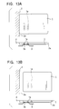
- Fig. 13A indicates a condition where once an IC card 1 is inserted into an inmost area of an insertion section 2a of a connector 2, a plurality of contact points la provided on the bottom surface of the IC card 1 will get in contact with a plurality of terminals 3 of the connector 2.
- Each terminal 3 has a contact portion 3a protruding toward the insertion section 2a.
- a detecting switch be provided in the IC card connector so as to detect whether or not the IC card has been properly inserted in the card insertion section.
- Such kind of detecting switch is so constructed that it may be driven (pushed) by the IC card just before the completion of its insertion, thereby effecting an On/Off change-over for the contact points. Accordingly, if the IC card has not been completely inserted in a predetermined position as shown in Fig. 13B, the detecting switch will not operate.
- the detecting switch may be effectively used to avoid any possible damages to various electronic components, which damages may otherwise occur due to an uncompleted contact between the contact points of the IC card and the terminals of the connector, or caused because the contact points of the IC card and the terminals of the connector are contacted with each other in undesired positions.
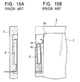
- Figs. 14 and 15 are explanatory views illustrating a prior art where a detecting switch has been incorporated in an IC card connector.
- Figs. 14A and 14B are explanatory views illustrating a condition where a detecting switch is in a waiting position when viewed from one side and from the above
- Figs. 15A and 15B are explanatory views illustrating a condition where a detecting switch is in its detecting position when viewed from one side and from the above.
- a detecting switch 4 is provided in a position adjacent to an inmost position of the insertion section 2a so as to detect whether or not an IC card has been fully inserted in position.
- Such detecting switch 4 includes an actuator 4a which is made of an electrically conductive material and is fixed in position through one end thereof in a manner such that it is flexibly deformable in a direction in which the IC card is inserted or pulled out.
- the detecting switch 4 is so arranged that it faces a contact element 4b and may get in contact with or leave the contact element 4b.
- the IC card 1 upon being inserted in the inmost position of the card insertion section 2a, will receive a clamping force from both sides thereof due to a contact pressure caused by the terminals of the connector 2, the IC card 1 may be held in a loading position of the card insertion section 2a.
- the actuator 4a when the IC card 1 has been inserted in the loading position of the card insertion section 2a, the actuator 4a will be pressed inwardly by the IC card 1. At this moment, a reaction force will be generated by the actuator 4a, causing the IC card 1 to be urged in a direction in which the IC card is to be discharged.
- an object of the present invention to provide an improved IC card connector capable of preventing an IC card from being pressed outwardly by a detecting switch, even if a long period use causes a deterioration in a clamping force of the connector for clamping the IC card.
- an IC card connector comprising: a housing including a card insertion section into which an IC card may be inserted; a plurality of terminals each having a cantilever beam configuration secured through one end thereof on the housing, and each having a contact portion on a free end thereof, said contact portion being formed in a manner such that it is protruding toward the card insertion section; a detecting switch located adjacent to an inmost position of the card insertion section, said detecting switch including an actuator and a contact element, the actuator being made of an electrically conductive material and adapted to be driven by an IC card just before the completion of its insertion, said actuator being also capable of coming into contact with the contact element and moving away therefrom so as to detect whether the insertion of the IC card is completed or not.
- the actuator of the detecting switch is provided with a projected tongue piece obliquely protruding toward the card insertion section, in a manner such that the projected tongue piece is adapted to be driven in the IC card's thickness direction by the IC card just before the completion of its insertion.
- the actuator is fixed at a base end thereof on the housing so that a free end thereof is capable of getting into contact with the contact element and moving away therefrom, said actuator is further provided with the projected tongue piece at a middle position between the free end and the base end thereof, in a manner such that the projected tongue piece is protruding toward the outside of the actuator.
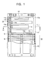
- Fig. 1 is a partially sectional plane view illustrating an IC card connector made according to an embodiment of the present invention.
- Fig. 2 is a cross sectional view illustrating the IC card connector of Fig. 1, taken along II-II line thereof.
- Fig. 3 is an explanatory view illustrating terminals provided on the IC card connector wherein the IC card has not been inserted.
- Fig. 4 is an explanatory view illustrating a condition where the IC card has been inserted only half way in a card insertion section.
- Fig. 5 is an explanatory view illustrating a relative positional relationship between the terminals of the connector and contact points of the IC card, when the IC card and the connector are in a condition shown in Fig. 4.
- Fig. 6 is an explanatory view illustrating a condition just before the IC card is fully inserted in the IC card insertion section.
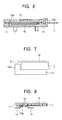
- Fig. 7 is an enlarged view illustrating an important portion of Fig. 6.
- Fig. 8 is an explanatory view illustrating a relative positional relationship between the terminals of the connector and the contact points of the IC card, when the IC card and the connector are in a condition shown in Fig. 6.
- Fig. 9 is an explanatory view illustrating a condition where the IC card has been completely inserted in position in the card insertion section.
- Fig. 10 is an explanatory view illustrating a relative positional relationship between the terminals of the connector and the contact points of the IC card, when the IC card and the connector are in a condition shown in Fig. 9.
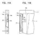
- Fig. 11A is an explanatory view illustrating a condition where a detecting switch is in a waiting position when viewed from one side.
- Fig. 11B is an explanatory view illustrating a condition where a detecting switch is in a waiting position when viewed from the above.
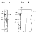
- Fig. 12A is an explanatory view illustrating a condition where a detecting switch is in its detecting position when viewed from one side.
- Fig. 12B is an explanatory view illustrating a condition where a detecting switch is in its detecting position when viewed from the above.
- Figs. 13A and 13B are explanatory views indicating a necessity of employing a detecting switch.
- Figs. 14A and 14B are explanatory views illustrating a condition where a detecting switch is in a waiting position when viewed from one side and from the above.
- Figs. 15A and 15B are explanatory views illustrating a condition where a detecting switch is in its detecting position when viewed from one side and from the above.
- Fig. 1 is a partially sectional plane view illustrating an IC card connector made according to an embodiment of the present invention
- Fig. 2 is a cross sectional view illustrating the IC card connector of Fig. 1, taken along II-II line thereof
- Fig. 3 is an explanatory view illustrating terminals provided on the IC card connector wherein the IC card has not been inserted
- Fig. 4 is an explanatory view illustrating a condition where the IC card has been inserted only half way in a card insertion section
- Fig. 1 is a partially sectional plane view illustrating an IC card connector made according to an embodiment of the present invention
- Fig. 2 is a cross sectional view illustrating the IC card connector of Fig. 1, taken along II-II line thereof
- Fig. 3 is an explanatory view illustrating terminals provided on the IC card connector wherein the IC card has not been inserted
- Fig. 4 is an explanatory view illustrating a condition where the IC card has been inserted
- FIG. 5 is an explanatory view illustrating a relative positional relationship between the terminals of the connector and contact points of the IC card, when the IC card and the connector are in a condition shown in Fig. 4;
- Fig. 6 is an explanatory view illustrating a condition just before the IC card is fully inserted in the IC card insertion section;
- Fig. 7 is an enlarged view illustrating an important portion of Fig. 6;
- Fig. 8 is an explanatory view illustrating a relative positional relationship between the terminals of the connector and the contact points of the IC card, when the IC card and the connector are in a condition shown in Fig. 6;
- Fig. 6 is an explanatory view illustrating a relative positional relationship between the terminals of the connector and the contact points of the IC card, when the IC card and the connector are in a condition shown in Fig. 6;
- FIG. 9 is an explanatory view illustrating a condition where the IC card has been completely inserted in position in the card insertion section;
- Fig. 10 is an explanatory view illustrating a relative positional relationship between the terminals of the connector and the contact points of the IC card, when the IC card and the connector are in a condition shown in Fig. 6;
- Fig. 11A is an explanatory view illustrating a condition where a detecting switch is in a waiting position when viewed from one side;
- Fig. 11B is an explanatory view illustrating a condition where a detecting switch is in a waiting position when viewed from the above;
- FIG. 12A is an explanatory view illustrating a condition where a detecting switch is in its detecting position when viewed from one side;
- Fig. 12B is an explanatory view illustrating a condition where a detecting switch is in its detecting position when viewed from the above.
- a connector for use with an IC card comprises a base 11 made of a synthetic resin, an upper cover 12 also made of a synthetic resin, both of which are connected together in a manner as shown in the drawings.
- the base 11 and the upper cover 1 together form a housing 10 having a card insertion section 10a.
- a plurality of terminals 13 each having a convex contact portion 13a at its free end, are proved on the base 11 in a manner such that each terminal 13 is fixed in position through one end thereof.
- a detecting switch 14 is installed on the base 11 to detect whether or not an IC card 1 has been completely inserted in position in the card insertion section 10a.
- an elongate elastic member 15 is fixed through one end thereof on the base 11, in a manner such that it is extending in the IC card's insertion direction (shown by an arrow in Fig. 1). Further, an elongate leaf spring 16 is provided on the base 11 so that an IC card inserted in the card insertion section 10a will be pressed against the upper cover 12, thereby providing the upper cover 12 with a guiding function.
- the plurality of terminals 13 are provided corresponding to a plurality of contact points 1a formed on the bottom surface of the IC card 1.
- the contact portion of each of the terminals 13 is formed to protrude to some extent toward the interior of the card insertion section 10a.
- the elongate elastic member 15 is formed on the free end thereof with a click projection 15a which is protruding toward the interior of the card insertion section 10a and will be driven by the front end portion of the IC card just before the IC card is completely inserted in a predetermined position of the card insertion position 10a.
- the click projection 15a is designed so as to be located in the vicinity of the detecting switch 14.
- the detecting switch 14 is provided close to an inmost position of the card insertion section 10a, and has an actuator 14a and a contact element 14b.
- the actuator 14a is made of an electrically conductive material (such as a metal) and is fixed at one end thereof on a predetermined position in a manner such that it is elastically deformable in the thickness direction the housing 10. In more detail, the actuator 14 is so arranged that it can freely get contact with or leave the contact element 14b.
- the actuator 14a has a projected tongue piece 14c located in generally middle position between the free end and the base end of the actuator 14a. In further detail, the projected tongue piece 14c is so arranged that it is downwardly inclined towards the card insertion section 10a. Moreover, the projected tongue piece 14c is so formed that it may be driven and pressed inwardly by the front portion of the IC card 1 just before it is completely inserted in a predetermined position in the card insertion section 10a.
- the metal actuator 14a due to its own rigidity, will be kept spaced apart from the contact element 14b, so that the detecting switch is in its OFF position.
- the IC card 1 has been fully inserted in the inmost position of the card insertion section 10a, since the front end portion of the IC card I will get in contact with the projected piece 14c of the actuator 14a, the projected tongue piece 14c will be pressed in a downward direction.
- the free end of the actuator 14a is pressed downwardly by the projected tongue piece 14c so as to get contact with the contact element 14b, thereby rendering the detecting switch 14 to be in its ON position. Therefore, if it is found that the detecting switch 14 has been changed over from its OFF state to its ON state, a user can determine that the IC card 1 has been completely inserted in a predetermined position in the card insertion section 10a.
- the projected tongue piece 14c is pressed downwardly and this causes the actuator 14a to be pressed downwardly, thus a reaction force (elastic force) will occur on the actuator 14a.
- the reaction force (elastic force) of the actuator 14a is directed upwardly in a direction generally perpendicular to the IC card discharge direction, the IC card 1 may be prevented from being pushed in the IC card discharge direction, so as to avoid a problem of position deviation of an inserted IC card.
- the elastic piece 15 As shown in Figs. 2 and 3, when an IC card has not been fully inserted in position in the card insertion section 10a, the elastic piece 15 will be kept parallel with the upper cover 12 without any bending. At this time, the click projection 15a on the free end of the elastic piece 15 is protruding to some extent in the vicinity of the detecting switch 14 toward the interior of the card insertion section 10a. Meanwhile, the contact portions 13a of the terminals 13 are also protruding to some extent toward the interior of the card insertion section 10a.
- the click projection 15a of the elastic piece 15 will not receive any external force from the IC card 1 until the IC card 1 has reached the inmost position of the IC card insertion section 10a. At this time, as shown in Fig. 7, a small clearance is formed between the upper end of the click projection 15a and the upper cover 12. Further, the small clearance has a thickness which is less than 1/2 of the thickness of the IC card 1.
- the front end portion of the IC card 1 will press down the elastic piece 15 and then move beyond the click projection 15a so as to get in contact with the inner wall of the base 11. Meanwhile, the contact points formed on the bottom surface of the IC card 1 come into contact with the corresponding contact portions 13a of the terminals 13. Namely, the insertion of the IC card 1 may be considered to have been completed soon after a person inserting the IC card gets a click feeling caused due to the click projection 15a, then the IC card 1 may be kept in a predetermined position (a loading position) in the card insertion section 10a. Further, referring again to Figs.
- the click projection 15a since the click projection 15a is located at a position just adjacent to the projected tongue piece 14c of the detecting switch 14, the front end portion of the IC card 1 will press down the click projection 15a, so that the projected tongue piece 14c will also be pressed down, thereby pressing down the actuator 14. In this way, soon after a person gets a click feeling, the detecting switch 14 will be changed over from its OFF state to its ON state, thereby permitting the person to detect whether the IC card 1 has been completely inserted in position in the card insertion section 10a.
- the IC card 1 when the IC card 1 is pulled out of the card insertion section 10a, the IC card 1 will move from the loading position (shown in Figs. 9 and 10), so that the click projection 15a will be moved upwardly by virtue of an elasticity of the elastic piece 15.
- the actuator 14a will leave the contact element 14b, also by virtue of its own elasticity. In this way, the detecting switch 14 will be changed over from its ON position to its OFF position. Further, the contact portions 13a of the terminals 13 will be moved upwardly towards the card insertion section 10a due to an elasticity of each terminal 13, so that the IC card connector may return to its original condition as shown in Figs. 2 and 3.
- the actuator of the detecting switch is provided with a projected tongue piece obliquely protruding toward the card insertion section, in a manner such that the projected tongue piece is adapted to be driven in the IC card's thickness direction by the IC card just before the completion of its insertion. Therefore, an elastic force of the actuator (this force will exert on the IC card which has been inserted in its loading position) may be made generally orthogonal to the IC card's discharge direction.
- the actuator is fixed at a base end thereof on the housing so that a free end thereof is capable of getting into contact with the contact element and moving away therefrom, said actuator is further provided with the projected tongue piece at a middle position between the free end and the base end thereof, in a manner such that the projected tongue piece is protruding toward the outside of the actuator. Therefore, by merely slightly pressing the projected tongue piece, it will be possible for a free end of the actuator to obtain a large stroke movement, thus making it sure to more exactly perform an On/Off change-over of the detecting switch.
Abstract
Description
- The present invention relates to a connector for use with an IC card, which connector is employed to send signal into or obtain signal from the IC card inserted in position. In particular, the present invention provides an improvement for a detecting switch contained in the connector, so as to effectively detect whether or not the IC card has been inserted in position.
- An IC card is a card provided with an integral circuit capable of performing a predetermined calculation and an information storing. Usually, such an IC card is used as a medium to perform a desired information processing in an information processing machine such as a personal computer or digital camera. Further, a personal computer or a digital camera is equipped with a connector (for use with the IC card) which has a plurality of terminals corresponding to a plurality of contact points provided on the bottom surface of the IC card.
- Such an IC card connector is usually formed with an insertion section into which an IC card may be inserted, so that once an IC card is completely inserted in position, the plurality of contact points of the IC card may get in contact with the plurality of terminals of the connector, thereby permitting a desired signal transmission.
- Fig. 13A indicates a condition where once an
IC card 1 is inserted into an inmost area of aninsertion section 2a of aconnector 2, a plurality of contact points la provided on the bottom surface of theIC card 1 will get in contact with a plurality ofterminals 3 of theconnector 2. Eachterminal 3 has acontact portion 3a protruding toward theinsertion section 2a. - With the above structure, if the
IC card 1 is inserted into theinsertion section 2a but has not reached a predetermined loading position as shown in Fig. 13B, the contact points la of theIC card 1 will not get in contact with thecorresponding terminals 3. As a result, it is impossible to perform a predetermined signal transmission. - In order to solve the above problem, there has been suggested that a detecting switch be provided in the IC card connector so as to detect whether or not the IC card has been properly inserted in the card insertion section. Such kind of detecting switch is so constructed that it may be driven (pushed) by the IC card just before the completion of its insertion, thereby effecting an On/Off change-over for the contact points. Accordingly, if the IC card has not been completely inserted in a predetermined position as shown in Fig. 13B, the detecting switch will not operate. In this way, the detecting switch may be effectively used to avoid any possible damages to various electronic components, which damages may otherwise occur due to an uncompleted contact between the contact points of the IC card and the terminals of the connector, or caused because the contact points of the IC card and the terminals of the connector are contacted with each other in undesired positions.
- Figs. 14 and 15 are explanatory views illustrating a prior art where a detecting switch has been incorporated in an IC card connector. In more detail, Figs. 14A and 14B are explanatory views illustrating a condition where a detecting switch is in a waiting position when viewed from one side and from the above, Figs. 15A and 15B are explanatory views illustrating a condition where a detecting switch is in its detecting position when viewed from one side and from the above.
- As shown in Figs. 14 and 15, a detecting
switch 4 is provided in a position adjacent to an inmost position of theinsertion section 2a so as to detect whether or not an IC card has been fully inserted in position. Such detectingswitch 4 includes anactuator 4a which is made of an electrically conductive material and is fixed in position through one end thereof in a manner such that it is flexibly deformable in a direction in which the IC card is inserted or pulled out. In fact, the detectingswitch 4 is so arranged that it faces acontact element 4b and may get in contact with or leave thecontact element 4b. - Referring again to Fig. 14B, when the
IC card 1 has not reached a predetermined inmost position in the card insertion section, theactuator 4a is elastically urged against thecontact member 4b due to its own elasticity, so that the detectingswitch 4 is in an ON position. On the other hand, as shown in Fig. 15B, when theIC card 1 has reached the predetermined inmost position, since a front portion of theIC card 1 is caused to press theactuator 4a in the same direction in which the IC card is inserted, theactuator 4a will be urged away from thecontact element 4b, thereby rendering the detectingswitch 4 to be in its Off position. In this manner, by virtue of On/Off change-over operation of thedetecting switch 4, it is sure to detect whether or not the IC card has been inserted properly (in the inmost position) in the ICcard insertion section 2a. - In this way, the
IC card 1, upon being inserted in the inmost position of thecard insertion section 2a, will receive a clamping force from both sides thereof due to a contact pressure caused by the terminals of theconnector 2, theIC card 1 may be held in a loading position of thecard insertion section 2a. Hence, when theIC card 1 has been inserted in the loading position of thecard insertion section 2a, theactuator 4a will be pressed inwardly by theIC card 1. At this moment, a reaction force will be generated by theactuator 4a, causing theIC card 1 to be urged in a direction in which the IC card is to be discharged. This, however, will cause a deterioration in the clamping force of the connector 1 (for clamping the IC card when it is in an inserted position) with the passing of time. As a result, even though theIC card 1 may be properly inserted in position in the ICcard insertion section 2a, the IC card will be urged by the reaction force of theactuator 4a in a direction the IC card is to be discharged, hence theIC card 1 is likely to deviate from its correct position, making it impossible to perform a predetermined signal transmission. - In view of the above discussed problems associated with the above mentioned prior arts, it is an object of the present invention to provide an improved IC card connector capable of preventing an IC card from being pressed outwardly by a detecting switch, even if a long period use causes a deterioration in a clamping force of the connector for clamping the IC card.
- According to an aspect of the present invention, there is provided an IC card connector, comprising: a housing including a card insertion section into which an IC card may be inserted; a plurality of terminals each having a cantilever beam configuration secured through one end thereof on the housing, and each having a contact portion on a free end thereof, said contact portion being formed in a manner such that it is protruding toward the card insertion section; a detecting switch located adjacent to an inmost position of the card insertion section, said detecting switch including an actuator and a contact element, the actuator being made of an electrically conductive material and adapted to be driven by an IC card just before the completion of its insertion, said actuator being also capable of coming into contact with the contact element and moving away therefrom so as to detect whether the insertion of the IC card is completed or not. In particular, the actuator of the detecting switch is provided with a projected tongue piece obliquely protruding toward the card insertion section, in a manner such that the projected tongue piece is adapted to be driven in the IC card's thickness direction by the IC card just before the completion of its insertion.
- According to an aspect of the present invention, the actuator is fixed at a base end thereof on the housing so that a free end thereof is capable of getting into contact with the contact element and moving away therefrom, said actuator is further provided with the projected tongue piece at a middle position between the free end and the base end thereof, in a manner such that the projected tongue piece is protruding toward the outside of the actuator.
- Embodiments of the invention will now be described, by way of example only, with reference to the accompanying drawings, in which:
- Fig. 1 is a partially sectional plane view illustrating an IC card connector made according to an embodiment of the present invention.
- Fig. 2 is a cross sectional view illustrating the IC card connector of Fig. 1, taken along II-II line thereof.
- Fig. 3 is an explanatory view illustrating terminals provided on the IC card connector wherein the IC card has not been inserted.
- Fig. 4 is an explanatory view illustrating a condition where the IC card has been inserted only half way in a card insertion section.
- Fig. 5 is an explanatory view illustrating a relative positional relationship between the terminals of the connector and contact points of the IC card, when the IC card and the connector are in a condition shown in Fig. 4.
- Fig. 6 is an explanatory view illustrating a condition just before the IC card is fully inserted in the IC card insertion section.
- Fig. 7 is an enlarged view illustrating an important portion of Fig. 6.
- Fig. 8 is an explanatory view illustrating a relative positional relationship between the terminals of the connector and the contact points of the IC card, when the IC card and the connector are in a condition shown in Fig. 6.
- Fig. 9 is an explanatory view illustrating a condition where the IC card has been completely inserted in position in the card insertion section.
- Fig. 10 is an explanatory view illustrating a relative positional relationship between the terminals of the connector and the contact points of the IC card, when the IC card and the connector are in a condition shown in Fig. 9.
- Fig. 11A is an explanatory view illustrating a condition where a detecting switch is in a waiting position when viewed from one side.
- Fig. 11B is an explanatory view illustrating a condition where a detecting switch is in a waiting position when viewed from the above.
- Fig. 12A is an explanatory view illustrating a condition where a detecting switch is in its detecting position when viewed from one side.
- Fig. 12B is an explanatory view illustrating a condition where a detecting switch is in its detecting position when viewed from the above.
- Figs. 13A and 13B are explanatory views indicating a necessity of employing a detecting switch.
- Figs. 14A and 14B are explanatory views illustrating a condition where a detecting switch is in a waiting position when viewed from one side and from the above.
- Figs. 15A and 15B are explanatory views illustrating a condition where a detecting switch is in its detecting position when viewed from one side and from the above.
- An embodiment of the present invention will be described with reference to the companying drawings in which: Fig. 1 is a partially sectional plane view illustrating an IC card connector made according to an embodiment of the present invention; Fig. 2 is a cross sectional view illustrating the IC card connector of Fig. 1, taken along II-II line thereof; Fig. 3 is an explanatory view illustrating terminals provided on the IC card connector wherein the IC card has not been inserted; Fig. 4 is an explanatory view illustrating a condition where the IC card has been inserted only half way in a card insertion section; Fig. 5 is an explanatory view illustrating a relative positional relationship between the terminals of the connector and contact points of the IC card, when the IC card and the connector are in a condition shown in Fig. 4; Fig. 6 is an explanatory view illustrating a condition just before the IC card is fully inserted in the IC card insertion section; Fig. 7 is an enlarged view illustrating an important portion of Fig. 6; Fig. 8 is an explanatory view illustrating a relative positional relationship between the terminals of the connector and the contact points of the IC card, when the IC card and the connector are in a condition shown in Fig. 6; Fig. 9 is an explanatory view illustrating a condition where the IC card has been completely inserted in position in the card insertion section; Fig. 10 is an explanatory view illustrating a relative positional relationship between the terminals of the connector and the contact points of the IC card, when the IC card and the connector are in a condition shown in Fig. 6; Fig. 11A is an explanatory view illustrating a condition where a detecting switch is in a waiting position when viewed from one side; Fig. 11B is an explanatory view illustrating a condition where a detecting switch is in a waiting position when viewed from the above; Fig. 12A is an explanatory view illustrating a condition where a detecting switch is in its detecting position when viewed from one side; Fig. 12B is an explanatory view illustrating a condition where a detecting switch is in its detecting position when viewed from the above.
- As shown in Figs. 1 and 2, a connector for use with an IC card, made according to an embodiment of the present invention, comprises a base 11 made of a synthetic resin, an
upper cover 12 also made of a synthetic resin, both of which are connected together in a manner as shown in the drawings. In fact, thebase 11 and theupper cover 1 together form ahousing 10 having acard insertion section 10a. A plurality ofterminals 13 each having aconvex contact portion 13a at its free end, are proved on the base 11 in a manner such that each terminal 13 is fixed in position through one end thereof. Moreover, a detectingswitch 14 is installed on the base 11 to detect whether or not anIC card 1 has been completely inserted in position in thecard insertion section 10a. In addition, an elongateelastic member 15 is fixed through one end thereof on thebase 11, in a manner such that it is extending in the IC card's insertion direction (shown by an arrow in Fig. 1). Further, anelongate leaf spring 16 is provided on the base 11 so that an IC card inserted in thecard insertion section 10a will be pressed against theupper cover 12, thereby providing theupper cover 12 with a guiding function. - The plurality of
terminals 13 are provided corresponding to a plurality ofcontact points 1a formed on the bottom surface of theIC card 1. In order to effect an elastic contact with the contact points la, the contact portion of each of theterminals 13 is formed to protrude to some extent toward the interior of thecard insertion section 10a. The elongateelastic member 15 is formed on the free end thereof with aclick projection 15a which is protruding toward the interior of thecard insertion section 10a and will be driven by the front end portion of the IC card just before the IC card is completely inserted in a predetermined position of thecard insertion position 10a. In particular, theclick projection 15a is designed so as to be located in the vicinity of the detectingswitch 14. The detectingswitch 14 is provided close to an inmost position of thecard insertion section 10a, and has anactuator 14a and acontact element 14b. Theactuator 14a is made of an electrically conductive material (such as a metal) and is fixed at one end thereof on a predetermined position in a manner such that it is elastically deformable in the thickness direction thehousing 10. In more detail, theactuator 14 is so arranged that it can freely get contact with or leave thecontact element 14b. Further, theactuator 14a has a projectedtongue piece 14c located in generally middle position between the free end and the base end of theactuator 14a. In further detail, the projectedtongue piece 14c is so arranged that it is downwardly inclined towards thecard insertion section 10a. Moreover, the projectedtongue piece 14c is so formed that it may be driven and pressed inwardly by the front portion of theIC card 1 just before it is completely inserted in a predetermined position in thecard insertion section 10a. - Namely, as shown in Figs. 11A and 11B, if the
IC card 1 has not been inserted in the inmost position of thecard insertion section 10a of thehousing 10, themetal actuator 14a, due to its own rigidity, will be kept spaced apart from thecontact element 14b, so that the detecting switch is in its OFF position. On the other hand, if theIC card 1 has been fully inserted in the inmost position of thecard insertion section 10a, since the front end portion of the IC card I will get in contact with the projectedpiece 14c of theactuator 14a, the projectedtongue piece 14c will be pressed in a downward direction. - In this manner, the free end of the
actuator 14a is pressed downwardly by the projectedtongue piece 14c so as to get contact with thecontact element 14b, thereby rendering the detectingswitch 14 to be in its ON position. Therefore, if it is found that the detectingswitch 14 has been changed over from its OFF state to its ON state, a user can determine that theIC card 1 has been completely inserted in a predetermined position in thecard insertion section 10a. - In this embodiment of the present invention, once the
IC card 1 is inserted into a predetermined position in thecard insertion section 10a, the projectedtongue piece 14c is pressed downwardly and this causes theactuator 14a to be pressed downwardly, thus a reaction force (elastic force) will occur on theactuator 14a. At this moment, since the reaction force (elastic force) of theactuator 14a is directed upwardly in a direction generally perpendicular to the IC card discharge direction, theIC card 1 may be prevented from being pushed in the IC card discharge direction, so as to avoid a problem of position deviation of an inserted IC card. This effect may remain the same all the time, even if a long period use will bring about a deterioration in a clamping force of the connector which is necessary for clamping the IC card when in its inserted condition. In addition, since the free end of theactuator 14a may be moved for a relatively long stroke by only slightly pressing down the projectedtongue piece 14c provided in a generally middle position between the free end and the base end of theactuator 14a, it is sure to exactly perform an ON/OFF change-over operation of the detectingswitch 14. - The function of the
elastic piece 15 and the insertion movement of theIC card 1 will be described in detail below. As shown in Figs. 2 and 3, when an IC card has not been fully inserted in position in thecard insertion section 10a, theelastic piece 15 will be kept parallel with theupper cover 12 without any bending. At this time, theclick projection 15a on the free end of theelastic piece 15 is protruding to some extent in the vicinity of the detectingswitch 14 toward the interior of thecard insertion section 10a. Meanwhile, thecontact portions 13a of theterminals 13 are also protruding to some extent toward the interior of thecard insertion section 10a. - On the other hand, as shown in Figs. 4 and 5, when an
IC card 1 is being inserted inwardly in thecard insertion section 10a, theIC card 1 will be guided by theupper cover plate 12 when in moving so as to get in contact with thecontact portions 13a of theterminals 13. Thus, as shown in Figs. 6 and 8, as soon as theIC card 1 is inserted further toward the inmost position of thecard insertion section 10a, the bottom surface of theIC card 1 will press down thecontact portions 13a of theterminals 13. In this way, all thecontact portions 13a of theterminals 13 will form an elastic contact with the bottom surface of theIC card 1, by virtue of an elasticity of theterminals 13 each of which is fixed at one end thereof on the connector. In fact, theclick projection 15a of theelastic piece 15 will not receive any external force from theIC card 1 until theIC card 1 has reached the inmost position of the ICcard insertion section 10a. At this time, as shown in Fig. 7, a small clearance is formed between the upper end of theclick projection 15a and theupper cover 12. Further, the small clearance has a thickness which is less than 1/2 of the thickness of theIC card 1. - Then, as fast as the
IC card 1 reaches the inmost position of thecard insertion section 10a, as shown in Figs. 9 and 10, the front end portion of theIC card 1 will press down theelastic piece 15 and then move beyond theclick projection 15a so as to get in contact with the inner wall of thebase 11. Meanwhile, the contact points formed on the bottom surface of theIC card 1 come into contact with thecorresponding contact portions 13a of theterminals 13. Namely, the insertion of theIC card 1 may be considered to have been completed soon after a person inserting the IC card gets a click feeling caused due to theclick projection 15a, then theIC card 1 may be kept in a predetermined position (a loading position) in thecard insertion section 10a. Further, referring again to Figs. 1 and 2, since theclick projection 15a is located at a position just adjacent to the projectedtongue piece 14c of the detectingswitch 14, the front end portion of theIC card 1 will press down theclick projection 15a, so that the projectedtongue piece 14c will also be pressed down, thereby pressing down theactuator 14. In this way, soon after a person gets a click feeling, the detectingswitch 14 will be changed over from its OFF state to its ON state, thereby permitting the person to detect whether theIC card 1 has been completely inserted in position in thecard insertion section 10a. Therefore, after a person has inserted an IC card into thecard insertion section 10a, he can confirm whether or not the IC card has been properly inserted in position, by observing a sound and a vibration which will occur at the time when the click feeling has been felt. - On the other hand, when the
IC card 1 is pulled out of thecard insertion section 10a, theIC card 1 will move from the loading position (shown in Figs. 9 and 10), so that theclick projection 15a will be moved upwardly by virtue of an elasticity of theelastic piece 15. At the same time, theactuator 14a will leave thecontact element 14b, also by virtue of its own elasticity. In this way, the detectingswitch 14 will be changed over from its ON position to its OFF position. Further, thecontact portions 13a of theterminals 13 will be moved upwardly towards thecard insertion section 10a due to an elasticity of each terminal 13, so that the IC card connector may return to its original condition as shown in Figs. 2 and 3. - As is understood from the above description, with the use of the present invention, it is possible to obtain at least the following effects.
- Namely, in the IC card connector of the present invention, the actuator of the detecting switch is provided with a projected tongue piece obliquely protruding toward the card insertion section, in a manner such that the projected tongue piece is adapted to be driven in the IC card's thickness direction by the IC card just before the completion of its insertion. Therefore, an elastic force of the actuator (this force will exert on the IC card which has been inserted in its loading position) may be made generally orthogonal to the IC card's discharge direction. In this way, with the passing of time even if there will occur a deterioration in a clamping force of the connector for clamping the IC card, the IC card will not be pushed by the detecting switch in its discharge direction and thus it is possible to avoid a position deviation of the IC card when in its inserted position, thereby increasing its reliability in use.
- Further, in the IC card connector of the present invention, the actuator is fixed at a base end thereof on the housing so that a free end thereof is capable of getting into contact with the contact element and moving away therefrom, said actuator is further provided with the projected tongue piece at a middle position between the free end and the base end thereof, in a manner such that the projected tongue piece is protruding toward the outside of the actuator. Therefore, by merely slightly pressing the projected tongue piece, it will be possible for a free end of the actuator to obtain a large stroke movement, thus making it sure to more exactly perform an On/Off change-over of the detecting switch.
Claims (2)
- An IC card connector, comprising:a housing including a card insertion section into which an IC card may be inserted;a plurality of terminals each having a cantilever beam configuration secured through one end thereof on the housing, and each having a contact portion on a free end thereof, said contact portion being formed in a manner such that it is protruding toward the card insertion section;a detecting switch located adjacent to an inmost position of the card insertion section, said detecting switch including an actuator and a contact element, the actuator being made of an electrically conductive material and adapted to be driven by an IC card just before the completion of its insertion, said actuator being also capable of coming into contact with the contact element and moving away therefrom so as to detect whether the insertion of the IC card is completed or not,wherein the actuator of the detecting switch is provided with a projected tongue piece obliquely protruding toward the card insertion section, in a manner such that the projected tongue piece is adapted to be driven in the IC card's thickness direction by the IC card just before the completion of its insertion.
- The IC card connector according to claim 1, wherein the actuator is fixed at a base end thereof on the housing so that a free end thereof is capable of getting into contact with the contact element and moving away therefrom, said actuator is further provided with the projected tongue piece at a middle position between the free end and the base end thereof, in a manner such that the projected tongue piece is protruding toward the outside of the actuator.
Applications Claiming Priority (3)
| Application Number | Priority Date | Filing Date | Title |
|---|---|---|---|
| JP250634/97 | 1997-09-16 | ||
| JP25063497A JP3288277B2 (en) | 1997-09-16 | 1997-09-16 | IC card connector |
| JP25063497 | 1997-09-16 |
Publications (3)
| Publication Number | Publication Date |
|---|---|
| EP0908981A2 true EP0908981A2 (en) | 1999-04-14 |
| EP0908981A3 EP0908981A3 (en) | 2000-12-20 |
| EP0908981B1 EP0908981B1 (en) | 2003-04-02 |
Family
ID=17210781
Family Applications (1)
| Application Number | Title | Priority Date | Filing Date |
|---|---|---|---|
| EP98307051A Expired - Lifetime EP0908981B1 (en) | 1997-09-16 | 1998-09-02 | IC card connector |
Country Status (4)
| Country | Link |
|---|---|
| US (1) | US6059592A (en) |
| EP (1) | EP0908981B1 (en) |
| JP (1) | JP3288277B2 (en) |
| DE (1) | DE69812831T2 (en) |
Cited By (10)
| Publication number | Priority date | Publication date | Assignee | Title |
|---|---|---|---|---|
| WO2001043237A1 (en) * | 1999-12-09 | 2001-06-14 | Yamaichi Electronics Co., Ltd. | Write protect switch for card connectors |
| EP1146473A1 (en) * | 1999-11-08 | 2001-10-17 | Yamaichi Electrics Co., Ltd. | Card connector |
| EP1160931A2 (en) * | 2000-05-30 | 2001-12-05 | Alps Electric Co., Ltd. | Card connector device |
| EP1172899A1 (en) * | 2000-07-10 | 2002-01-16 | Alps Electric Co., Ltd. | Connector device for card with detection switch for detecting fitting of card |
| WO2002007269A2 (en) * | 2000-06-29 | 2002-01-24 | Molex Incorporated | Ic card connector |
| US6558199B2 (en) | 2000-07-06 | 2003-05-06 | Alps Electric Co., Ltd. | Connector device for card with a plurality of connection terminals different in length |
| US6638087B1 (en) | 1999-11-05 | 2003-10-28 | Yamaichi Electronics Co., Ltd. | Switch structure of card connector |
| WO2006122085A2 (en) * | 2005-05-09 | 2006-11-16 | Molex Incorporated | Card connector |
| EP1775802A1 (en) * | 2000-06-29 | 2007-04-18 | Molex Incorporated | IC card connector |
| CN100547857C (en) * | 2006-08-29 | 2009-10-07 | 日本航空电子工业株式会社 | Connector |
Families Citing this family (17)
| Publication number | Priority date | Publication date | Assignee | Title |
|---|---|---|---|---|
| JP3923310B2 (en) * | 1999-10-25 | 2007-05-30 | 三菱電機株式会社 | Portable information terminal |
| JP3635625B2 (en) * | 1999-11-05 | 2005-04-06 | 山一電機株式会社 | Card connector switch structure |
| TW452152U (en) * | 1999-11-15 | 2001-08-21 | Kinpo Elect Inc | Seat commonly used for dual memory cards |
| JP3333481B2 (en) * | 1999-11-16 | 2002-10-15 | 山一電機株式会社 | Card recognition switch for card connector |
| US6422876B1 (en) | 1999-12-08 | 2002-07-23 | Nortel Networks Limited | High throughput interconnection system using orthogonal connectors |
| JP3530460B2 (en) | 2000-04-27 | 2004-05-24 | 山一電機株式会社 | Card connector |
| JP2002358484A (en) * | 2001-05-31 | 2002-12-13 | Pioneer Electronic Corp | Information reproducing device |
| DE10203066A1 (en) * | 2002-01-28 | 2003-08-07 | Marconi Comm Gmbh | Printed circuit board assembly system and method for positioning printed circuit boards |
| JP3934528B2 (en) * | 2002-10-29 | 2007-06-20 | 日立オムロンターミナルソリューションズ株式会社 | Card processing device |
| US20070254713A1 (en) * | 2006-04-28 | 2007-11-01 | Isaac Lagnado | System and method for managing operation of a system based at least in part on a component of the system being physically accessible |
| KR100718753B1 (en) * | 2006-08-07 | 2007-05-15 | 벽산엔지니어링주식회사 | Forming device for construct drainage canal in the concrete structure |
| JP4855438B2 (en) * | 2008-04-24 | 2012-01-18 | アルプス電気株式会社 | Card connector |
| JP2011014311A (en) * | 2009-06-30 | 2011-01-20 | Fujitsu Ltd | Contact mechanism, card detection device, and card detecting method |
| JP4866459B2 (en) * | 2009-12-08 | 2012-02-01 | モレックス インコーポレイテド | Card connector |
| JP5727776B2 (en) * | 2010-12-14 | 2015-06-03 | タイコエレクトロニクスジャパン合同会社 | Detection switch structure and connector having the same |
| JP5655648B2 (en) * | 2011-03-15 | 2015-01-21 | 富士通株式会社 | Electronic device and circuit board connection structure |
| CN110059789B (en) * | 2019-03-28 | 2022-07-05 | 浙江佳鸿汽车科技股份有限公司 | Position storage device, position reading device and position reading method |
Citations (3)
| Publication number | Priority date | Publication date | Assignee | Title |
|---|---|---|---|---|
| DE1220920B (en) * | 1961-10-13 | 1966-07-14 | Fendt & Co Xaver | Electric socket with plug |
| DE1239385B (en) * | 1960-07-12 | 1967-04-27 | Hirschmann Radiotechnik | Switching contact set with small dimensions |
| US5370544A (en) * | 1991-11-12 | 1994-12-06 | Amphenol Tuchel Electronics Gmbh | Chip card reader with an end postition switch |
Family Cites Families (8)
| Publication number | Priority date | Publication date | Assignee | Title |
|---|---|---|---|---|
| FR2638293B1 (en) * | 1988-10-26 | 1991-01-18 | Itt Composants Instr | ELECTRICAL CONNECTOR FOR ELECTRONIC MEMORY CARDS, METHOD FOR PRODUCING SUCH A CONNECTOR AND READ-WRITE DEVICE INCLUDING SUCH A CONNECTOR |
| US5369259A (en) * | 1989-09-21 | 1994-11-29 | Amphenol Corporation | Chip card reader |
| FR2675929B1 (en) * | 1991-04-26 | 1993-07-02 | Cit Alcatel | CHIP CARD READER. |
| FR2695515B1 (en) * | 1992-09-09 | 1994-11-10 | Francelco Sa | Electrical connector for microcircuit card. |
| SG44631A1 (en) * | 1993-05-13 | 1997-12-19 | Molex Inc | IC pack connector apparatus with switch means |
| US5775937A (en) * | 1994-06-01 | 1998-07-07 | Itt Composants Et Instrumets | Card connector with switch |
| US5520551A (en) * | 1994-12-01 | 1996-05-28 | The Whitaker Corporation | Molded latching apparatus for printed circuit mounted components |
| US5674085A (en) * | 1996-05-24 | 1997-10-07 | The Whitaker Corporation | Electrical connector with switch |
-
1997
- 1997-09-16 JP JP25063497A patent/JP3288277B2/en not_active Expired - Fee Related
-
1998
- 1998-09-02 EP EP98307051A patent/EP0908981B1/en not_active Expired - Lifetime
- 1998-09-02 DE DE69812831T patent/DE69812831T2/en not_active Expired - Fee Related
- 1998-09-15 US US09/153,691 patent/US6059592A/en not_active Expired - Fee Related
Patent Citations (3)
| Publication number | Priority date | Publication date | Assignee | Title |
|---|---|---|---|---|
| DE1239385B (en) * | 1960-07-12 | 1967-04-27 | Hirschmann Radiotechnik | Switching contact set with small dimensions |
| DE1220920B (en) * | 1961-10-13 | 1966-07-14 | Fendt & Co Xaver | Electric socket with plug |
| US5370544A (en) * | 1991-11-12 | 1994-12-06 | Amphenol Tuchel Electronics Gmbh | Chip card reader with an end postition switch |
Cited By (23)
| Publication number | Priority date | Publication date | Assignee | Title |
|---|---|---|---|---|
| US6638087B1 (en) | 1999-11-05 | 2003-10-28 | Yamaichi Electronics Co., Ltd. | Switch structure of card connector |
| US6848923B2 (en) | 1999-11-05 | 2005-02-01 | Yamaichi Electronics Co., Ltd. | Switch structure of card connector |
| EP1146473A1 (en) * | 1999-11-08 | 2001-10-17 | Yamaichi Electrics Co., Ltd. | Card connector |
| EP1146473A4 (en) * | 1999-11-08 | 2004-04-07 | Yamaichi Electrics Co Ltd | Card connector |
| US6692276B1 (en) | 1999-11-08 | 2004-02-17 | Yamaichi Electronics Co., Ltd. | Card connector |
| EP1152499A1 (en) * | 1999-12-09 | 2001-11-07 | Yamaichi Electrics Co., Ltd. | Write protect switch for card connectors |
| WO2001043237A1 (en) * | 1999-12-09 | 2001-06-14 | Yamaichi Electronics Co., Ltd. | Write protect switch for card connectors |
| EP1152499A4 (en) * | 1999-12-09 | 2002-06-05 | Yamaichi Electrics Co Ltd | Write protect switch for card connectors |
| US6709281B2 (en) | 1999-12-09 | 2004-03-23 | Yamaichi Electronics Co., Ltd. | Write protect switch for card connector |
| EP1160931A2 (en) * | 2000-05-30 | 2001-12-05 | Alps Electric Co., Ltd. | Card connector device |
| EP1160931A3 (en) * | 2000-05-30 | 2003-04-09 | Alps Electric Co., Ltd. | Card connector device |
| WO2002007269A2 (en) * | 2000-06-29 | 2002-01-24 | Molex Incorporated | Ic card connector |
| WO2002007269A3 (en) * | 2000-06-29 | 2002-09-06 | Molex Inc | Ic card connector |
| EP1775802A1 (en) * | 2000-06-29 | 2007-04-18 | Molex Incorporated | IC card connector |
| US6558199B2 (en) | 2000-07-06 | 2003-05-06 | Alps Electric Co., Ltd. | Connector device for card with a plurality of connection terminals different in length |
| US6488528B2 (en) | 2000-07-10 | 2002-12-03 | Alps Electric Co., Ltd. | Connector device for card with detection switch for detecting fitting of card |
| EP1172899A1 (en) * | 2000-07-10 | 2002-01-16 | Alps Electric Co., Ltd. | Connector device for card with detection switch for detecting fitting of card |
| WO2006122085A2 (en) * | 2005-05-09 | 2006-11-16 | Molex Incorporated | Card connector |
| WO2006122085A3 (en) * | 2005-05-09 | 2007-03-29 | Molex Inc | Card connector |
| KR100952240B1 (en) * | 2005-05-09 | 2010-04-09 | 몰렉스 인코포레이티드 | Card connector |
| US7887348B2 (en) | 2005-05-09 | 2011-02-15 | Molex Incorporated | Card connector |
| CN101218592B (en) * | 2005-05-09 | 2012-05-30 | 莫列斯公司 | Card connector |
| CN100547857C (en) * | 2006-08-29 | 2009-10-07 | 日本航空电子工业株式会社 | Connector |
Also Published As
| Publication number | Publication date |
|---|---|
| US6059592A (en) | 2000-05-09 |
| DE69812831T2 (en) | 2003-11-13 |
| EP0908981A3 (en) | 2000-12-20 |
| DE69812831D1 (en) | 2003-05-08 |
| JP3288277B2 (en) | 2002-06-04 |
| EP0908981B1 (en) | 2003-04-02 |
| JPH1197110A (en) | 1999-04-09 |
Similar Documents
| Publication | Publication Date | Title |
|---|---|---|
| EP0908981B1 (en) | IC card connector | |
| KR100952240B1 (en) | Card connector | |
| US6399906B1 (en) | Switch for a card connector | |
| US7029287B2 (en) | Electrical connector in which a wiping action is carried out in a narrow area | |
| US7137836B2 (en) | Card connector with detect switch | |
| US6609919B2 (en) | Card connector | |
| US6390836B1 (en) | Card connector | |
| KR100289475B1 (en) | Electrical switch assembly | |
| US6576853B2 (en) | Switch exhibition non-unidirectional displacement | |
| JP2000506638A (en) | Smart card and smart card connector | |
| JP2001357931A (en) | Card connector | |
| US5924881A (en) | Electrical connector for IC card | |
| US6179638B1 (en) | Connector for use in a card reader | |
| US6130387A (en) | Card detecting switch | |
| US6896532B2 (en) | Switch terminal for memory card connectors | |
| JP4866459B2 (en) | Card connector | |
| JP4469805B2 (en) | Card connector | |
| EP0908837B1 (en) | IC card connector | |
| JPH10240874A (en) | Card reader | |
| US7794281B2 (en) | Card connector | |
| JP3640343B2 (en) | Card connector | |
| JP2000048915A (en) | Card connector | |
| US8115130B2 (en) | Electronic device | |
| US7019243B2 (en) | Lever switch | |
| KR20000062626A (en) | Push switch |
Legal Events
| Date | Code | Title | Description |
|---|---|---|---|
| PUAI | Public reference made under article 153(3) epc to a published international application that has entered the european phase |
Free format text: ORIGINAL CODE: 0009012 |
|
| AK | Designated contracting states |
Kind code of ref document: A2 Designated state(s): DE FR GB |
|
| AX | Request for extension of the european patent |
Free format text: AL;LT;LV;MK;RO;SI |
|
| PUAL | Search report despatched |
Free format text: ORIGINAL CODE: 0009013 |
|
| AK | Designated contracting states |
Kind code of ref document: A3 Designated state(s): AT BE CH CY DE DK ES FI FR GB GR IE IT LI LU MC NL PT SE |
|
| AX | Request for extension of the european patent |
Free format text: AL;LT;LV;MK;RO;SI |
|
| RIC1 | Information provided on ipc code assigned before grant |
Free format text: 7H 01R 23/72 A, 7H 01R 13/703 B, 7G 06K 7/00 B |
|
| 17P | Request for examination filed |
Effective date: 20010108 |
|
| AKX | Designation fees paid |
Free format text: DE FR GB |
|
| GRAH | Despatch of communication of intention to grant a patent |
Free format text: ORIGINAL CODE: EPIDOS IGRA |
|
| RIC1 | Information provided on ipc code assigned before grant |
Free format text: 7H 01R 12/22 A, 7H 01R 13/703 B, 7G 06K 7/00 B |
|
| GRAH | Despatch of communication of intention to grant a patent |
Free format text: ORIGINAL CODE: EPIDOS IGRA |
|
| GRAA | (expected) grant |
Free format text: ORIGINAL CODE: 0009210 |
|
| AK | Designated contracting states |
Designated state(s): DE FR GB |
|
| REG | Reference to a national code |
Ref country code: GB Ref legal event code: FG4D |
|
| REF | Corresponds to: |
Ref document number: 69812831 Country of ref document: DE Date of ref document: 20030508 Kind code of ref document: P |
|
| ET | Fr: translation filed | ||
| PLBE | No opposition filed within time limit |
Free format text: ORIGINAL CODE: 0009261 |
|
| STAA | Information on the status of an ep patent application or granted ep patent |
Free format text: STATUS: NO OPPOSITION FILED WITHIN TIME LIMIT |
|
| 26N | No opposition filed |
Effective date: 20040105 |
|
| PGFP | Annual fee paid to national office [announced via postgrant information from national office to epo] |
Ref country code: FR Payment date: 20060925 Year of fee payment: 9 |
|
| PGFP | Annual fee paid to national office [announced via postgrant information from national office to epo] |
Ref country code: GB Payment date: 20070802 Year of fee payment: 10 |
|
| PGFP | Annual fee paid to national office [announced via postgrant information from national office to epo] |
Ref country code: DE Payment date: 20071126 Year of fee payment: 10 |
|
| REG | Reference to a national code |
Ref country code: FR Ref legal event code: ST Effective date: 20080531 |
|
| PG25 | Lapsed in a contracting state [announced via postgrant information from national office to epo] |
Ref country code: FR Free format text: LAPSE BECAUSE OF NON-PAYMENT OF DUE FEES Effective date: 20071001 |
|
| GBPC | Gb: european patent ceased through non-payment of renewal fee |
Effective date: 20080902 |
|
| PG25 | Lapsed in a contracting state [announced via postgrant information from national office to epo] |
Ref country code: DE Free format text: LAPSE BECAUSE OF NON-PAYMENT OF DUE FEES Effective date: 20090401 |
|
| PG25 | Lapsed in a contracting state [announced via postgrant information from national office to epo] |
Ref country code: GB Free format text: LAPSE BECAUSE OF NON-PAYMENT OF DUE FEES Effective date: 20080902 |